EP1508688A1 - Fuel supply system and fuel pressure regulator - Google Patents
Fuel supply system and fuel pressure regulator Download PDFInfo
- Publication number
- EP1508688A1 EP1508688A1 EP20020728186 EP02728186A EP1508688A1 EP 1508688 A1 EP1508688 A1 EP 1508688A1 EP 20020728186 EP20020728186 EP 20020728186 EP 02728186 A EP02728186 A EP 02728186A EP 1508688 A1 EP1508688 A1 EP 1508688A1
- Authority
- EP
- European Patent Office
- Prior art keywords
- fuel
- chamber
- pressure
- case
- valve unit
- Prior art date
- Legal status (The legal status is an assumption and is not a legal conclusion. Google has not performed a legal analysis and makes no representation as to the accuracy of the status listed.)
- Withdrawn
Links
Images



Classifications
-
- F—MECHANICAL ENGINEERING; LIGHTING; HEATING; WEAPONS; BLASTING
- F02—COMBUSTION ENGINES; HOT-GAS OR COMBUSTION-PRODUCT ENGINE PLANTS
- F02M—SUPPLYING COMBUSTION ENGINES IN GENERAL WITH COMBUSTIBLE MIXTURES OR CONSTITUENTS THEREOF
- F02M37/00—Apparatus or systems for feeding liquid fuel from storage containers to carburettors or fuel-injection apparatus; Arrangements for purifying liquid fuel specially adapted for, or arranged on, internal-combustion engines
- F02M37/04—Feeding by means of driven pumps
- F02M37/08—Feeding by means of driven pumps electrically driven
- F02M37/10—Feeding by means of driven pumps electrically driven submerged in fuel, e.g. in reservoir
-
- F—MECHANICAL ENGINEERING; LIGHTING; HEATING; WEAPONS; BLASTING
- F02—COMBUSTION ENGINES; HOT-GAS OR COMBUSTION-PRODUCT ENGINE PLANTS
- F02M—SUPPLYING COMBUSTION ENGINES IN GENERAL WITH COMBUSTIBLE MIXTURES OR CONSTITUENTS THEREOF
- F02M37/00—Apparatus or systems for feeding liquid fuel from storage containers to carburettors or fuel-injection apparatus; Arrangements for purifying liquid fuel specially adapted for, or arranged on, internal-combustion engines
- F02M37/04—Feeding by means of driven pumps
- F02M37/08—Feeding by means of driven pumps electrically driven
- F02M37/10—Feeding by means of driven pumps electrically driven submerged in fuel, e.g. in reservoir
- F02M37/106—Feeding by means of driven pumps electrically driven submerged in fuel, e.g. in reservoir the pump being installed in a sub-tank
-
- F—MECHANICAL ENGINEERING; LIGHTING; HEATING; WEAPONS; BLASTING
- F02—COMBUSTION ENGINES; HOT-GAS OR COMBUSTION-PRODUCT ENGINE PLANTS
- F02M—SUPPLYING COMBUSTION ENGINES IN GENERAL WITH COMBUSTIBLE MIXTURES OR CONSTITUENTS THEREOF
- F02M37/00—Apparatus or systems for feeding liquid fuel from storage containers to carburettors or fuel-injection apparatus; Arrangements for purifying liquid fuel specially adapted for, or arranged on, internal-combustion engines
- F02M37/22—Arrangements for purifying liquid fuel specially adapted for, or arranged on, internal-combustion engines, e.g. arrangements in the feeding system
- F02M37/32—Arrangements for purifying liquid fuel specially adapted for, or arranged on, internal-combustion engines, e.g. arrangements in the feeding system characterised by filters or filter arrangements
- F02M37/44—Filters structurally associated with pumps
-
- F—MECHANICAL ENGINEERING; LIGHTING; HEATING; WEAPONS; BLASTING
- F02—COMBUSTION ENGINES; HOT-GAS OR COMBUSTION-PRODUCT ENGINE PLANTS
- F02M—SUPPLYING COMBUSTION ENGINES IN GENERAL WITH COMBUSTIBLE MIXTURES OR CONSTITUENTS THEREOF
- F02M37/00—Apparatus or systems for feeding liquid fuel from storage containers to carburettors or fuel-injection apparatus; Arrangements for purifying liquid fuel specially adapted for, or arranged on, internal-combustion engines
- F02M37/22—Arrangements for purifying liquid fuel specially adapted for, or arranged on, internal-combustion engines, e.g. arrangements in the feeding system
- F02M37/32—Arrangements for purifying liquid fuel specially adapted for, or arranged on, internal-combustion engines, e.g. arrangements in the feeding system characterised by filters or filter arrangements
- F02M37/46—Filters structurally associated with pressure regulators
-
- F—MECHANICAL ENGINEERING; LIGHTING; HEATING; WEAPONS; BLASTING
- F02—COMBUSTION ENGINES; HOT-GAS OR COMBUSTION-PRODUCT ENGINE PLANTS
- F02M—SUPPLYING COMBUSTION ENGINES IN GENERAL WITH COMBUSTIBLE MIXTURES OR CONSTITUENTS THEREOF
- F02M37/00—Apparatus or systems for feeding liquid fuel from storage containers to carburettors or fuel-injection apparatus; Arrangements for purifying liquid fuel specially adapted for, or arranged on, internal-combustion engines
- F02M37/22—Arrangements for purifying liquid fuel specially adapted for, or arranged on, internal-combustion engines, e.g. arrangements in the feeding system
- F02M37/32—Arrangements for purifying liquid fuel specially adapted for, or arranged on, internal-combustion engines, e.g. arrangements in the feeding system characterised by filters or filter arrangements
- F02M37/50—Filters arranged in or on fuel tanks
-
- F—MECHANICAL ENGINEERING; LIGHTING; HEATING; WEAPONS; BLASTING
- F02—COMBUSTION ENGINES; HOT-GAS OR COMBUSTION-PRODUCT ENGINE PLANTS
- F02M—SUPPLYING COMBUSTION ENGINES IN GENERAL WITH COMBUSTIBLE MIXTURES OR CONSTITUENTS THEREOF
- F02M69/00—Low-pressure fuel-injection apparatus ; Apparatus with both continuous and intermittent injection; Apparatus injecting different types of fuel
- F02M69/16—Low-pressure fuel-injection apparatus ; Apparatus with both continuous and intermittent injection; Apparatus injecting different types of fuel characterised by means for metering continuous fuel flow to injectors or means for varying fuel pressure upstream of continuously or intermittently operated injectors
- F02M69/26—Low-pressure fuel-injection apparatus ; Apparatus with both continuous and intermittent injection; Apparatus injecting different types of fuel characterised by means for metering continuous fuel flow to injectors or means for varying fuel pressure upstream of continuously or intermittently operated injectors the means varying fuel pressure in a fuel by-pass passage, the pressure acting on a throttle valve against the action of metered or throttled fuel pressure for variably throttling fuel flow to injection nozzles, e.g. to keep constant the pressure differential at the metering valve
-
- F—MECHANICAL ENGINEERING; LIGHTING; HEATING; WEAPONS; BLASTING
- F02—COMBUSTION ENGINES; HOT-GAS OR COMBUSTION-PRODUCT ENGINE PLANTS
- F02M—SUPPLYING COMBUSTION ENGINES IN GENERAL WITH COMBUSTIBLE MIXTURES OR CONSTITUENTS THEREOF
- F02M69/00—Low-pressure fuel-injection apparatus ; Apparatus with both continuous and intermittent injection; Apparatus injecting different types of fuel
- F02M69/46—Details, component parts or accessories not provided for in, or of interest apart from, the apparatus covered by groups F02M69/02 - F02M69/44
- F02M69/54—Arrangement of fuel pressure regulators
-
- Y—GENERAL TAGGING OF NEW TECHNOLOGICAL DEVELOPMENTS; GENERAL TAGGING OF CROSS-SECTIONAL TECHNOLOGIES SPANNING OVER SEVERAL SECTIONS OF THE IPC; TECHNICAL SUBJECTS COVERED BY FORMER USPC CROSS-REFERENCE ART COLLECTIONS [XRACs] AND DIGESTS
- Y10—TECHNICAL SUBJECTS COVERED BY FORMER USPC
- Y10T—TECHNICAL SUBJECTS COVERED BY FORMER US CLASSIFICATION
- Y10T137/00—Fluid handling
- Y10T137/7722—Line condition change responsive valves
- Y10T137/7758—Pilot or servo controlled
- Y10T137/7762—Fluid pressure type
- Y10T137/7764—Choked or throttled pressure type
- Y10T137/7766—Choked passage through main valve head
-
- Y—GENERAL TAGGING OF NEW TECHNOLOGICAL DEVELOPMENTS; GENERAL TAGGING OF CROSS-SECTIONAL TECHNOLOGIES SPANNING OVER SEVERAL SECTIONS OF THE IPC; TECHNICAL SUBJECTS COVERED BY FORMER USPC CROSS-REFERENCE ART COLLECTIONS [XRACs] AND DIGESTS
- Y10—TECHNICAL SUBJECTS COVERED BY FORMER USPC
- Y10T—TECHNICAL SUBJECTS COVERED BY FORMER US CLASSIFICATION
- Y10T137/00—Fluid handling
- Y10T137/7722—Line condition change responsive valves
- Y10T137/7837—Direct response valves [i.e., check valve type]
- Y10T137/7838—Plural
-
- Y—GENERAL TAGGING OF NEW TECHNOLOGICAL DEVELOPMENTS; GENERAL TAGGING OF CROSS-SECTIONAL TECHNOLOGIES SPANNING OVER SEVERAL SECTIONS OF THE IPC; TECHNICAL SUBJECTS COVERED BY FORMER USPC CROSS-REFERENCE ART COLLECTIONS [XRACs] AND DIGESTS
- Y10—TECHNICAL SUBJECTS COVERED BY FORMER USPC
- Y10T—TECHNICAL SUBJECTS COVERED BY FORMER US CLASSIFICATION
- Y10T137/00—Fluid handling
- Y10T137/8593—Systems
- Y10T137/87265—Dividing into parallel flow paths with recombining
- Y10T137/87555—Having direct response valve [e.g., check valve, etc.]
Definitions
- the present invention relates to a fuel supply apparatus that is fitted inside a fuel tank in a vehicle, etc., for pressurizing and supplying fuel to an injector that injects fuel into the engine, and the invention also relates to a fuel pressure regulator for regulating fuel pressure to a predetermined value.
- Fig. 4 is a sectional side view of a conventional fuel supply apparatus disclosed in Int'l . Pat. App. Pub. No. WO96-23967.
- a fuel supply apparatus 1 integrally comprises a cover 3, a fuel pump 4, a fuel filter 5, a fuel pressure regulator 6, a discharge pipe 7, and a fuel level gauge and an electrical connector that are not illustrated in the figure, and the apparatus is suspended from an opening 2a of a fuel tank 2 formed of metal or resin.
- the fuel filter 5 comprises a holding member 5a, formed of electrically conductive resin and a filter element 5b contained therein, and is welded, liquid-tight, at its boundary portion 8 to the cover 3.
- the holding member 5a in its center portion holds the fuel pump 4, and at its lower end holds the fuel pressure regulator 6 and the fuel level gauge which is not illustrated.
- a gasket 9 is interposed to maintain an airtight seal between the cover 3 and the fuel tank 2.
- an inlet 10 as a fuel inlet for the fuel filter 5 is provided in the upper inside periphery of the holding member 5a, and is connected via a sealing member 10a to a discharge pipe 11 of the fuel pump 4.
- the holding member 5a of the fuel filter 5 has two fuel outlets.
- a channel 12 (indicated by the dotted-dashed line) , which forms the first fuel outlet, extends from the lower end of the holding member 5a axially in an upward direction.
- the channel 12 connects with the discharge pipe 7 provided on the cover 3 and supplies fuel, that has been filtered, to an injector.
- a return path 13, forming the second fuel outlet, is provided in the lower portion of the holding member 5a, and is connected to the fuel pressure regulator 6.
- Reference numeral 14 is a pump filter, and when the fuel in the fuel tank 2 is drawn into the fuel pump 4, the pump filter 14 filters out foreign particles from the fuel tank 2, such as iron powder, etc.
- the fuel pressure regulator 6 is fixed by inserting a base 6a into an insertion member 5c that extends downward from the bottom portion of the holding member 5a.
- a diaphragm 6c is interposed between an opening end of the base 6a and a housing 6b, and the diaphragm 6c is supported by a movable valve seat 6e provided with a discharge orifice 6d.
- a stationary valve seat 6f that co-functions with the movable valve seat 6e is fixed inside the base 6a.
- a spring 6g is contained between the housing 6b and the diaphragm 6c, and, at the lower portion of the housing 6b, a discharge outlet 6h is disposed to discharge the fuel from the discharge orifice 6d into the fuel tank 2.
- Reference numeral 4a is an electric current supply unit for supplying current to a motor, not illustrated, for the fuel pump 4, and the electric current supply unit 4a is connected electrically to the electrical connector, not illustrated, which is formed integrally with the cover 3.
- the fuel supply apparatus 1 configured in this way, electric current is supplied from a power supply, such as a storage battery, etc., not illustrated, via the electric current supply unit 4a, to the motor, not illustrated, of the fuel pump 4.
- a power supply such as a storage battery, etc.
- the electric current supply unit 4a to the motor, not illustrated, of the fuel pump 4.
- the fuel in the fuel tank 2 is taken in through the pump filter 14, and after being discharged from the discharge pipe 11, it flows through a channel 15 in the direction of arrow A, then passes through the filter element 5b, and arrives at a lower space 16 under the filer element 5b.
- the fuel flows into the fuel pressure regulator 6, and when fuel pressure in the base 6a becomes higher than the set pressure of the spring 6g, the diaphragm 6c moves to the housing 6b side, opening the discharge orifice 6d of the movable valve seat 6e and discharging the fuel in the base 6a to the fuel tank 2 again (returning flow volume) via the discharge outlet 6h, and the remaining volume flows through the channel 12 in the direction of arrow B and is supplied at a predetermined pressure through the discharge pipe 7 to the injector, in a fuel injection device mounted on an engine, which is not illustrated.
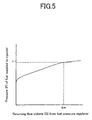
- Fig. 5 is a pressure characteristic diagram of the conventional fuel supply apparatus, illustrating the relation between the returning flow volume (Q) discharged from the fuel pressure regulator 6 to the fuel tank 2, and the fuel pressure (P) of the fuel supplied to the injector.
- the conventional fuel supply apparatus 1 configured as described above, ensures that the pressure of the fuel delivered under pressure to the injector is above a predetermined pressure Pi, and supplies the fuel to the injector of the fuel injection apparatus attached to the engine.
- the voltage supplied to the fuel pump 4 drops abruptly and the discharging performance of the fuel pump 4 deteriorates, or if the fuel that is supplied to the engine abruptly increases, the returning flow volume drops (shifts to the left in the diagram), and thus the problem has occurred that the fuel delivered under pressure to the injector cannot be ensured at the predetermined pressure Pi, and the injector cannot inject the fuel required by the engine.
- the present invention is made to solve the above-described problems, and it has as an object the provision of a fuel supply apparatus in which, if the returning flow volume (Q) drops, the pressure of the fuel delivered under pressure to the injector does not drop.
- a fuel supply apparatus related to the present invention comprises: a cover fitted to an opening of a fuel tank, and on which a discharge pipe is disposed; a fuel pump for delivering under pressure fuel from the fuel tank to an injector of an engine via the discharge pipe; a fuel filter for filtering the fuel discharged from the fuel pump; and a fuel pressure regulator for regulating the pressure of the fuel discharged from the fuel pump to a predetermined pressure; wherein the fuel pressure regulator includes: a first chamber, formed in a case, into which fuel discharged from the fuel pump flows, and a second chamber, into which the fuel flows via the first chamber; a fuel limiting means disposed between the first chamber and the second chamber, for limiting fuel flowing from the first chamber into the second chamber; a pilot valve unit having a passageway for opening to discharge fuel into the fuel tank when the fuel pressure in the second chamber is more than a first set pressure; and a main valve unit having a passageway for opening to discharge fuel into the fuel tank when the fuel pressure in the first chamber is equal to a second set pressure between
- the main valve unit comprises: a first valve for opening and closing a first communicating hole connecting the first chamber with the fuel tank, and a first elastic member for pressing on the first valve, wherein the first valve is held such that it can slide on a slide portion of the case, and a fuel control means is realized by a gap formed between the slide portion and the first valve.
- the first valve slides smoothly, and the fuel control means can be formed by a simple structure.
- a diffusing member is installed for dispersal of fuel being returned from the main valve unit to the fuel tank.
- a pore is situated in the first valve. In this way, control of the fuel flowing from the first chamber into the second chamber is easy and pressure characteristics of the fuel supply apparatus can be set to desired characteristics.
- a fuel pressure regulator in another aspect of the present invention, comprises: a first chamber formed in the case, into which fuel discharged from the fuel pump flows, and a second chamber, into which the fuel flows via the first chamber; a fuel limiting means disposed between the first chamber and the second chamber, for limiting fuel flowing from the first chamber into the second chamber; a first communicating hole for connecting the first chamber with the exterior of the case; a second communicating hole for connecting the second chamber with the exterior of the case; a pilot valve unit for opening to discharge through the second communicating hole, fuel to the exterior of the case when the fuel pressure in the second chamber is more than the first set pressure; and a main valve unit for opening and closing to discharge, through the first communicating hole, fuel to the exterior of the case when the fuel pressure of the first chamber is equal to the second set pressure between the first set pressure and the predetermined pressure.
- a diffusing member is installed for dispersal of fuel discharged from the main valve unit to the exterior of the case.
- Fig. 1 is a sectional side view of a fuel supply apparatus in an embodiment of the present invention.
- the fuel supply apparatus 100 integrally comprises a cover 3, a fuel pump 4, a fuel filter 5, a discharge pipe 7, a pump filter 14, a fuel pressure regulator 60, and a fuel level gauge (not illustrated), and the apparatus is suspended from an opening 2a of a fuel tank 2 formed of metal or resin.
- the fuel filter 5 comprises a holding member 5a formed of electrically conductive resin and a filter element 5b contained therein, and is welded, liquid-tight, at its boundary portion 8 to the cover 3.
- the holding member 5a in its center portion holds the fuel pump 4, and at its lower end holds the fuel level gauge (not illustrated).
- a gasket 9 is interposed to maintain an airtight seal between the cover 3 and the fuel tank 2.
- an inlet 10 as a fuel inlet for the fuel filter 5 is provided in the upper inside periphery of the holding member 5a, and is connected via a sealing member 10a to a discharge pipe 11 of the fuel pump 4.
- a channel 12 (indicated by a dotted-dashed line), which forms the fuel outlet of the fuel filter 5, is disposed in the holding member 5a, and extends from the lower end of the holding member 5a axially in an upward direction.
- the channel 12 communicates with the discharge pipe 7 provided in the cover 3 and supplies fuel, which has been filtered, to an injector.
- the fuel pressure regulator 60 which is disposed on the cover 3 outer surface where it is over a passageway (hereinafter fuel pipe) through which the fuel from the channel 12 flows via the discharge pipe 7 to the injector, detects the fuel pressure.
- Reference numeral 14 is a pump filter that filters out foreign particles, such as iron powder, etc., when the fuel in the fuel tank 2 is drawn into the fuel pump 4.
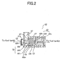
- Fig. 2 is an enlarged sectional side view of the fuel pressure regulator of Fig. 1
- Fig. 3 is a diagram of pressure characteristics of the fuel supply apparatus in an embodiment of the present invention.
- the fuel pressure regulator 60 comprises a first chamber 62 formed in a case 61, into which the fuel discharged from the fuel pump 4 flows, and a second chamber 63, into which the fuel flows via the first chamber 62; a pilot valve unit 65 that, when the fuel pressure of the second chamber 63 is more than a first set pressure Pp (indicated in Fig. 3), opens its passageway and discharges the fuel into the fuel tank 2; and a main valve unit 66 that, when the fuel pressure of the first chamber 62 reaches a second set pressure Pm (indicated in Fig. 3) between the first set pressure Pp (indicated in Fig. 3) and a predetermined pressure Pi (indicated in Fig. 3), opens its passageway and discharges the fuel into the fuel tank 2.
- the main valve unit 66 comprises a first valve 66b that opens and closes a first communicating hole 66a which connects the first chamber 62 with the fuel tank 2, and a first elastic member 66c that presses on the first valve 66b.
- a cylindrical portion 66b1 of the first valve 66b is held such that it can slide on a slide portion 61a of the case 61, and a gap 64 as fuel control means is formed between the cylindrical portion 66b1 and the slide portion 61a, wherein the fuel flowing from the first chamber 62 into the second chamber 63 is limited by the gap 64.
- the pilot valve unit 65 comprises a second valve 65b that opens and closes a second communicating hole 65a, which connects the second chamber 63 with the fuel tank 2, and a second elastic member 65c that presses on the second valve 65b.
- Reference numeral 67 is a pore having a predetermined cross sectional area, situated in the first valve 66b and forming a fuel control means similar to the gap 64; it limits the fuel flowing from the first chamber 62 into the second chamber 63, whereby the pressure characteristics for the fuel supply apparatus shown in Fig. 3 are determined. It should be understood that the pore 67 is furnished as may be necessary; the fuel control means may be formed by the gap 64 only.
- Reference numeral 68 is a diffusing member which is formed, for example, by a disk or disks having a plurality of holes, and is firmly fixed to a boss portion 61b of the case 61; the fuel discharged from the first communicating hole 66a to the fuel tank 2 is diffused through a plurality of percolating holes 68a, so that generation of abnormal noise, which accompanies high pressure injection of fuel to the fuel supply apparatus 100 and the fuel tank 2, is prevented.
- a current is supplied to a motor (not illustrated) of the fuel pump 4 via an electric current supply unit 4a from an electric power source, such as a storage battery (not illustrated); when the motor rotates, the fuel pump 4 activates; after the fuel in the fuel tank 2 is drawn in through the pump filter 14, it is discharged from the discharge pipe 11, flows along a passageway 15 in the direction of arrow A (illustrated in Fig. 1), and after passing the filter element 5b, the fuel arrives at a lower space 16 under the filter element 5b, and in addition it flows along the channel 12 in the direction of arrow B, passing through the discharge pipe 7, and is supplied to the injector of a fuel injection apparatus fitted to an engine (not illustrated).
- an electric power source such as a storage battery
- the fuel flows in the direction of arrow B and also flows in the direction of arrow C, and after flowing into the first chamber 62 of the fuel pressure regulator 60, it passes through the gap 64 as well as the pore 67, which are the fuel control means, and flows into the second chamber 63.
- the first valve 66b opposes the biasing force of the first elastic member 66c, whereby the cylindrical portion 66b1 slides along the slide portion 61a of the case 61, and moves in the right direction in Fig. 2, opening its passageway, and the fuel of the first chamber 62 flows in the direction of arrow E (illustrated in Fig. 1) and discharges to the fuel tank 2.
- gradient F of the dropping pressure is dependent on cross sectional area, length and shape of the gap 64 and the pore 67, which are the fuel control means, and also on the biasing force of the first elastic member 66c which sets the second set pressure Pm, so that by adjusting these items to an optimum value, the gradient F of the dropping pressure is set to as low a value as possible.
- the fuel supply apparatus is appropriate as an apparatus for keeping the pressure of the fuel delivered under pressure to an injector from dropping, even when the returning flow volume, which is returned from the fuel pressure regulator to the fuel tank, drops.
Landscapes
- Engineering & Computer Science (AREA)
- Chemical & Material Sciences (AREA)
- Combustion & Propulsion (AREA)
- Mechanical Engineering (AREA)
- General Engineering & Computer Science (AREA)
- Fuel-Injection Apparatus (AREA)
- Cooling, Air Intake And Gas Exhaust, And Fuel Tank Arrangements In Propulsion Units (AREA)
Abstract
A fuel supply apparatus having a fuel pressure
regulator (60) for regulating the pressure of fuel
discharged from a fuel pump (4) to a predetermined
pressure, the fuel pressure regulator (60) including:
a first chamber (62), formed in a case (61), into which
fuel discharged from the fuel pump (4) flows, and a
second chamber (63), into which the fuel flows via the
first chamber (62); a fuel limiting means (64) disposed
between the first chamber (62) and the second chamber
(63), for limiting fuel flowing from the first chamber
(62) into the second chamber (63); a pilot valve unit
(65) having a passageway for opening to discharge fuel
tank (2), when the fuel pressure in the second chamber
(63) is more than a first set pressure (Pp); and a main
valve unit (66) having a passageway for opening to
discharge fuel into the fuel tank (2) when the fuel
pressure in the first chamber (62) is equal to a second
set pressure (Pm) between the first set pressure (Pp)
and the predetermined pressure (Pi), whereby, in cases
where returning flow volume drops, the pressure of the
fuel delivered under pressure to the injector does not
drop.
Description
- The present invention relates to a fuel supply apparatus that is fitted inside a fuel tank in a vehicle, etc., for pressurizing and supplying fuel to an injector that injects fuel into the engine, and the invention also relates to a fuel pressure regulator for regulating fuel pressure to a predetermined value.
- Fig. 4 is a sectional side view of a conventional fuel supply apparatus disclosed in Int'l . Pat. App. Pub. No. WO96-23967.
- In the figure, a fuel supply apparatus 1 integrally comprises a
cover 3, afuel pump 4, afuel filter 5, a fuel pressure regulator 6, adischarge pipe 7, and a fuel level gauge and an electrical connector that are not illustrated in the figure, and the apparatus is suspended from an opening 2a of afuel tank 2 formed of metal or resin. - The
fuel filter 5 comprises aholding member 5a, formed of electrically conductive resin and afilter element 5b contained therein, and is welded, liquid-tight, at itsboundary portion 8 to thecover 3. Theholding member 5a in its center portion holds thefuel pump 4, and at its lower end holds the fuel pressure regulator 6 and the fuel level gauge which is not illustrated. Agasket 9 is interposed to maintain an airtight seal between thecover 3 and thefuel tank 2. - In the
holding member 5a of thefuel filter 5, aninlet 10 as a fuel inlet for thefuel filter 5 is provided in the upper inside periphery of theholding member 5a, and is connected via asealing member 10a to adischarge pipe 11 of thefuel pump 4. - Moreover, the
holding member 5a of thefuel filter 5 has two fuel outlets. A channel 12 (indicated by the dotted-dashed line) , which forms the first fuel outlet, extends from the lower end of theholding member 5a axially in an upward direction. Thechannel 12 connects with thedischarge pipe 7 provided on thecover 3 and supplies fuel, that has been filtered, to an injector. Areturn path 13, forming the second fuel outlet, is provided in the lower portion of theholding member 5a, and is connected to the fuel pressure regulator 6. -
Reference numeral 14 is a pump filter, and when the fuel in thefuel tank 2 is drawn into thefuel pump 4, thepump filter 14 filters out foreign particles from thefuel tank 2, such as iron powder, etc. - The fuel pressure regulator 6 is fixed by inserting a base 6a into an insertion member 5c that extends downward from the bottom portion of the
holding member 5a. A diaphragm 6c is interposed between an opening end of the base 6a and a housing 6b, and the diaphragm 6c is supported by amovable valve seat 6e provided with adischarge orifice 6d. - A stationary valve seat 6f that co-functions with the
movable valve seat 6e is fixed inside the base 6a. Aspring 6g is contained between the housing 6b and the diaphragm 6c, and, at the lower portion of the housing 6b, adischarge outlet 6h is disposed to discharge the fuel from thedischarge orifice 6d into thefuel tank 2. - Reference numeral 4a is an electric current supply unit for supplying current to a motor, not illustrated, for the
fuel pump 4, and the electric current supply unit 4a is connected electrically to the electrical connector, not illustrated, which is formed integrally with thecover 3. - In the fuel supply apparatus 1 configured in this way, electric current is supplied from a power supply, such as a storage battery, etc., not illustrated, via the electric current supply unit 4a, to the motor, not illustrated, of the
fuel pump 4. When the motor runs, the fuel in thefuel tank 2 is taken in through thepump filter 14, and after being discharged from thedischarge pipe 11, it flows through achannel 15 in the direction of arrow A, then passes through thefilter element 5b, and arrives at alower space 16 under thefiler element 5b. - Next, the fuel flows into the fuel pressure regulator 6, and when fuel pressure in the base 6a becomes higher than the set pressure of the
spring 6g, the diaphragm 6c moves to the housing 6b side, opening thedischarge orifice 6d of themovable valve seat 6e and discharging the fuel in the base 6a to thefuel tank 2 again (returning flow volume) via thedischarge outlet 6h, and the remaining volume flows through thechannel 12 in the direction of arrow B and is supplied at a predetermined pressure through thedischarge pipe 7 to the injector, in a fuel injection device mounted on an engine, which is not illustrated. - Fig. 5 is a pressure characteristic diagram of the conventional fuel supply apparatus, illustrating the relation between the returning flow volume (Q) discharged from the fuel pressure regulator 6 to the
fuel tank 2, and the fuel pressure (P) of the fuel supplied to the injector. When the returning flow volume (Q) is over Qm, the conventional fuel supply apparatus 1, configured as described above, ensures that the pressure of the fuel delivered under pressure to the injector is above a predetermined pressure Pi, and supplies the fuel to the injector of the fuel injection apparatus attached to the engine. - However, for example, if the voltage supplied to the
fuel pump 4 drops abruptly and the discharging performance of thefuel pump 4 deteriorates, or if the fuel that is supplied to the engine abruptly increases, the returning flow volume drops (shifts to the left in the diagram), and thus the problem has occurred that the fuel delivered under pressure to the injector cannot be ensured at the predetermined pressure Pi, and the injector cannot inject the fuel required by the engine. - The present invention is made to solve the above-described problems, and it has as an object the provision of a fuel supply apparatus in which, if the returning flow volume (Q) drops, the pressure of the fuel delivered under pressure to the injector does not drop.
- A fuel supply apparatus related to the present invention comprises: a cover fitted to an opening of a fuel tank, and on which a discharge pipe is disposed; a fuel pump for delivering under pressure fuel from the fuel tank to an injector of an engine via the discharge pipe; a fuel filter for filtering the fuel discharged from the fuel pump; and a fuel pressure regulator for regulating the pressure of the fuel discharged from the fuel pump to a predetermined pressure; wherein the fuel pressure regulator includes: a first chamber, formed in a case, into which fuel discharged from the fuel pump flows, and a second chamber, into which the fuel flows via the first chamber; a fuel limiting means disposed between the first chamber and the second chamber, for limiting fuel flowing from the first chamber into the second chamber; a pilot valve unit having a passageway for opening to discharge fuel into the fuel tank when the fuel pressure in the second chamber is more than a first set pressure; and a main valve unit having a passageway for opening to discharge fuel into the fuel tank when the fuel pressure in the first chamber is equal to a second set pressure between the first set pressure and the predetermined pressure.
- In this way, in cases where returning flow volume drops, the pressure of the fuel delivered under pressure to the injector does not drop.
- Preferably, the main valve unit comprises: a first valve for opening and closing a first communicating hole connecting the first chamber with the fuel tank, and a first elastic member for pressing on the first valve, wherein the first valve is held such that it can slide on a slide portion of the case, and a fuel control means is realized by a gap formed between the slide portion and the first valve.
- In this way, the first valve slides smoothly, and the fuel control means can be formed by a simple structure.
- Preferably, a diffusing member is installed for dispersal of fuel being returned from the main valve unit to the fuel tank.
- In this way, since the fuel discharged from the main valve unit is not injected at high pressure into the fuel tank and components of the fuel supply apparatus, abnormal noise due to fuel collision is not generated.
- Preferably, a pore is situated in the first valve. In this way, control of the fuel flowing from the first chamber into the second chamber is easy and pressure characteristics of the fuel supply apparatus can be set to desired characteristics.
- A fuel pressure regulator, in another aspect of the present invention, comprises: a first chamber formed in the case, into which fuel discharged from the fuel pump flows, and a second chamber, into which the fuel flows via the first chamber; a fuel limiting means disposed between the first chamber and the second chamber, for limiting fuel flowing from the first chamber into the second chamber; a first communicating hole for connecting the first chamber with the exterior of the case; a second communicating hole for connecting the second chamber with the exterior of the case; a pilot valve unit for opening to discharge through the second communicating hole, fuel to the exterior of the case when the fuel pressure in the second chamber is more than the first set pressure; and a main valve unit for opening and closing to discharge, through the first communicating hole, fuel to the exterior of the case when the fuel pressure of the first chamber is equal to the second set pressure between the first set pressure and the predetermined pressure.
- In this way, based on the pressure characteristics of the fuel pressure regulator, in cases where the returning flow volume drops, the fuel pressure does not drop.
- Preferably, a diffusing member is installed for dispersal of fuel discharged from the main valve unit to the exterior of the case.
- In this way, since the fuel discharged from the main valve unit is not injected at high pressure, abnormal noise due to the fuel collision is not generated.
-
- Fig. 1 is a sectional side view of a fuel supply apparatus in an embodiment of the present invention;
- Fig. 2 is an enlarged sectional side view of a fuel pressure regulator in Fig. 1;
- Fig. 3 is a pressure characteristic diagram for the fuel supply apparatus in an embodiment of the present invention;
- Fig. 4 is a sectional side view of a conventional fuel supply apparatus; and
- Fig. 5 is a pressure characteristic diagram for the conventional fuel supply apparatus.
-
- Fig. 1 is a sectional side view of a fuel supply apparatus in an embodiment of the present invention. In the figure, the
fuel supply apparatus 100 integrally comprises acover 3, afuel pump 4, afuel filter 5, adischarge pipe 7, apump filter 14, afuel pressure regulator 60, and a fuel level gauge (not illustrated), and the apparatus is suspended from an opening 2a of afuel tank 2 formed of metal or resin. - The
fuel filter 5 comprises aholding member 5a formed of electrically conductive resin and afilter element 5b contained therein, and is welded, liquid-tight, at itsboundary portion 8 to thecover 3. Theholding member 5a in its center portion holds thefuel pump 4, and at its lower end holds the fuel level gauge (not illustrated). Agasket 9 is interposed to maintain an airtight seal between thecover 3 and thefuel tank 2. - In the
holding member 5a of thefuel filter 5, aninlet 10 as a fuel inlet for thefuel filter 5 is provided in the upper inside periphery of theholding member 5a, and is connected via asealing member 10a to adischarge pipe 11 of thefuel pump 4. A channel 12 (indicated by a dotted-dashed line), which forms the fuel outlet of thefuel filter 5, is disposed in theholding member 5a, and extends from the lower end of theholding member 5a axially in an upward direction. - The
channel 12 communicates with thedischarge pipe 7 provided in thecover 3 and supplies fuel, which has been filtered, to an injector. Thefuel pressure regulator 60, which is disposed on thecover 3 outer surface where it is over a passageway (hereinafter fuel pipe) through which the fuel from thechannel 12 flows via thedischarge pipe 7 to the injector, detects the fuel pressure.Reference numeral 14 is a pump filter that filters out foreign particles, such as iron powder, etc., when the fuel in thefuel tank 2 is drawn into thefuel pump 4. - Fig. 2 is an enlarged sectional side view of the fuel pressure regulator of Fig. 1, and Fig. 3 is a diagram of pressure characteristics of the fuel supply apparatus in an embodiment of the present invention.
- In this figure, the
fuel pressure regulator 60 comprises afirst chamber 62 formed in acase 61, into which the fuel discharged from thefuel pump 4 flows, and asecond chamber 63, into which the fuel flows via thefirst chamber 62; apilot valve unit 65 that, when the fuel pressure of thesecond chamber 63 is more than a first set pressure Pp (indicated in Fig. 3), opens its passageway and discharges the fuel into thefuel tank 2; and amain valve unit 66 that, when the fuel pressure of thefirst chamber 62 reaches a second set pressure Pm (indicated in Fig. 3) between the first set pressure Pp (indicated in Fig. 3) and a predetermined pressure Pi (indicated in Fig. 3), opens its passageway and discharges the fuel into thefuel tank 2. - The
main valve unit 66 comprises afirst valve 66b that opens and closes a first communicating hole 66a which connects thefirst chamber 62 with thefuel tank 2, and a firstelastic member 66c that presses on thefirst valve 66b. A cylindrical portion 66b1 of thefirst valve 66b is held such that it can slide on aslide portion 61a of thecase 61, and agap 64 as fuel control means is formed between the cylindrical portion 66b1 and theslide portion 61a, wherein the fuel flowing from thefirst chamber 62 into thesecond chamber 63 is limited by thegap 64. - The
pilot valve unit 65 comprises asecond valve 65b that opens and closes a second communicatinghole 65a, which connects thesecond chamber 63 with thefuel tank 2, and a secondelastic member 65c that presses on thesecond valve 65b. -
Reference numeral 67 is a pore having a predetermined cross sectional area, situated in thefirst valve 66b and forming a fuel control means similar to thegap 64; it limits the fuel flowing from thefirst chamber 62 into thesecond chamber 63, whereby the pressure characteristics for the fuel supply apparatus shown in Fig. 3 are determined. It should be understood that thepore 67 is furnished as may be necessary; the fuel control means may be formed by thegap 64 only. -
Reference numeral 68 is a diffusing member which is formed, for example, by a disk or disks having a plurality of holes, and is firmly fixed to a boss portion 61b of thecase 61; the fuel discharged from the first communicating hole 66a to thefuel tank 2 is diffused through a plurality of percolatingholes 68a, so that generation of abnormal noise, which accompanies high pressure injection of fuel to thefuel supply apparatus 100 and thefuel tank 2, is prevented. - Next, using Fig. 1 to Fig. 3, operation of the
fuel supply apparatus 100 configured in this way is explained. - A current is supplied to a motor (not illustrated) of the
fuel pump 4 via an electric current supply unit 4a from an electric power source, such as a storage battery (not illustrated); when the motor rotates, thefuel pump 4 activates; after the fuel in thefuel tank 2 is drawn in through thepump filter 14, it is discharged from thedischarge pipe 11, flows along apassageway 15 in the direction of arrow A (illustrated in Fig. 1), and after passing thefilter element 5b, the fuel arrives at alower space 16 under thefilter element 5b, and in addition it flows along thechannel 12 in the direction of arrow B, passing through thedischarge pipe 7, and is supplied to the injector of a fuel injection apparatus fitted to an engine (not illustrated). - Regarding the fuel delivery process, the fuel flows in the direction of arrow B and also flows in the direction of arrow C, and after flowing into the
first chamber 62 of thefuel pressure regulator 60, it passes through thegap 64 as well as thepore 67, which are the fuel control means, and flows into thesecond chamber 63. - As the returning flow volume (Q) increases, when the fuel pressure of the
second chamber 63 reaches the first set pressure Pp (indicated in Fig.3), thesecond valve 65b moves in the right direction in Fig. 2 against the biasing force of the secondelastic member 65c, thereby opening the passageway, and the fuel in thesecond chamber 63 flows in the direction of arrow D (illustrated in Fig.1) and starts to discharge into thefuel tank 2. - Moreover, as the returning flow volume increases, when the fuel pressure of the
first chamber 62 reaches the second set pressure Pm between the first set pressure Pp (indicated in Fig. 3) and the predetermined pressure Pi, due to the pressure differential between the fuel pressure of thefirst chamber 62 and thesecond chamber 63, thefirst valve 66b opposes the biasing force of the firstelastic member 66c, whereby the cylindrical portion 66b1 slides along theslide portion 61a of thecase 61, and moves in the right direction in Fig. 2, opening its passageway, and the fuel of thefirst chamber 62 flows in the direction of arrow E (illustrated in Fig. 1) and discharges to thefuel tank 2. - Moreover, when the returning volume increases and reaches Qr (indicated in Fig. 3), the cylindrical portion 66b1 moves along the
slide portion 61a of thecase 61, increasing the fuel flowing in the direction of arrow E, whereby the fuel pressure of thefirst chamber 62 is regulated to the predetermined pressure Pi. - In this state, in which the fuel pressure of the
first chamber 62 is regulated to the predetermined pressure Pi, the injector of the fuel injection apparatus fitted to the engine (not illustrated), is stably supplied with the fuel. - Here, if the voltage supplying the
fuel pump 4 drops abruptly and the discharge performance of thefuel pump 4 deteriorates, or if the fuel supplying the engine increases abruptly, the return flow volume decreases (moves to left in Fig. 3), and with the flow volume decrease, the fuel pressure for supplying the injector drops, but because the gradient of the dropping pressure is low (indicated by F in Fig. 3), the fuel is stably supplied to the injector of the fuel injection apparatus fitted to the engine. - Moreover, gradient F of the dropping pressure is dependent on cross sectional area, length and shape of the
gap 64 and thepore 67, which are the fuel control means, and also on the biasing force of the firstelastic member 66c which sets the second set pressure Pm, so that by adjusting these items to an optimum value, the gradient F of the dropping pressure is set to as low a value as possible. - As described above, the fuel supply apparatus according to the present invention is appropriate as an apparatus for keeping the pressure of the fuel delivered under pressure to an injector from dropping, even when the returning flow volume, which is returned from the fuel pressure regulator to the fuel tank, drops.
Claims (6)
- A fuel supply apparatus comprising:a cover (3) fitted to an opening (2a) of a fuel tank (2), and on which a discharge pipe (7) is disposed;a fuel pump (4) for delivering under pressure fuel from said fuel tank (2) to an injector of an engine via said discharge pipe (7);a fuel filter (5) for filtering the fuel discharged from said fuel pump (4); anda fuel pressure regulator (60) for regulating the pressure of the fuel discharged from said fuel pump (4) to a predetermined pressure (Pi); wherein said fuel pressure regulator (60) includes:a first chamber (62), formed in a case (61), into which fuel discharged from said fuel pump (4) flows, and a second chamber (63), into which the fuel flows via the first chamber (62);a fuel limiting means (64) disposed between said first chamber (62) and said second chamber (63), for limiting fuel flowing from said first chamber (62) into said second chamber (63);a pilot valve unit (65) having a passageway for opening to discharge fuel into said fuel tank (2), when the fuel pressure in said second chamber (63) is more than a first set pressure (Pp); anda main valve unit (66) for opening and closing to discharge fuel into said fuel tank (2), when the fuel pressure in said first chamber (62) is equal to a second set pressure (Pm) between the first set pressure (Pp) and the predetermined pressure (Pi).
- A fuel supply apparatus according to claim 1, the main valve unit (66) comprising:a first valve (66b) for opening and closing a first communicating hole (66a) connecting said first chamber (62) with said fuel tank (2); anda first elastic member (66c) for pressing on said first valve (66b); wherein
said first valve (66b) is held such that it can slide on a slide portion (61a) of said case (61); and
a fuel control means is realized by a gap (64) formed between said slide portion (61a) and said first valve (66b). - A fuel supply apparatus according to claim 1, further comprising a diffusing member (68) installed for dispersal of fuel being returned from said main valve unit (66) to the fuel tank (2).
- A fuel supply apparatus according to claim 2, further comprising a pore (67) situated in said first valve (66b).
- A fuel pressure regulator for regulating, to a predetermined pressure (Pi), the pressure of fuel discharged from a fuel pump (4) comprising:a first chamber (62) formed in a case (61), into which fuel discharged from said fuel pump (4) flows, and a second chamber (63), into which the fuel flows via said first chamber (62);a fuel limiting means (64) disposed between said first chamber (62) and said second chamber (63), for limiting fuel flowing from said first chamber (62) into said second chamber (63);a first communicating hole (66a) for connecting said first chamber (62) with the exterior of said case (61);a second communicating hole (65a) for connecting said second chamber (63) with the exterior of said case (61);a pilot valve unit (65) for opening to discharge through the second communicating hole (65a) fuel to outside of said case (61), when the fuel pressure in said second chamber (63) is more than a first set pressure (Pp); anda main valve unit (66) for opening to discharge through the first communicating hole (66a) fuel to the exterior of said case (61), when the fuel pressure of said first chamber (62) is equal to a second set pressure (Pm) between the first set pressure (Pp) and the predetermined pressure (Pi).
- A fuel pressure regulator according to claim 5, further comprising a diffusing member (68) installed for dispersal of fuel discharged from said main valve unit (66) to the exterior of said case(61).
Applications Claiming Priority (1)
| Application Number | Priority Date | Filing Date | Title |
|---|---|---|---|
| PCT/JP2002/005212 WO2003100246A1 (en) | 2002-05-29 | 2002-05-29 | Fuel supply system and fuel pressure regulator |
Publications (1)
| Publication Number | Publication Date |
|---|---|
| EP1508688A1 true EP1508688A1 (en) | 2005-02-23 |
Family
ID=29561093
Family Applications (1)
| Application Number | Title | Priority Date | Filing Date |
|---|---|---|---|
| EP20020728186 Withdrawn EP1508688A1 (en) | 2002-05-29 | 2002-05-29 | Fuel supply system and fuel pressure regulator |
Country Status (6)
| Country | Link |
|---|---|
| US (1) | US6915787B2 (en) |
| EP (1) | EP1508688A1 (en) |
| JP (1) | JP3998017B2 (en) |
| CN (1) | CN100552210C (en) |
| TW (1) | TWI222493B (en) |
| WO (1) | WO2003100246A1 (en) |
Cited By (6)
| Publication number | Priority date | Publication date | Assignee | Title |
|---|---|---|---|---|
| EP2366886A1 (en) * | 2010-02-12 | 2011-09-21 | Synerject, LLC | Integrated fuel delivery module and methods of manufacture |
| US8079479B2 (en) | 2008-01-18 | 2011-12-20 | Synerject, Llc | In-tank fuel delivery module having an accessible fuel filter |
| US9004884B2 (en) | 2011-03-08 | 2015-04-14 | Synerject Llc | In-tank fluid transfer assembly |
| US9753443B2 (en) | 2014-04-21 | 2017-09-05 | Synerject Llc | Solenoid systems and methods for detecting length of travel |
| US9997287B2 (en) | 2014-06-06 | 2018-06-12 | Synerject Llc | Electromagnetic solenoids having controlled reluctance |
| US10260490B2 (en) | 2014-06-09 | 2019-04-16 | Synerject Llc | Methods and apparatus for cooling a solenoid coil of a solenoid pump |
Families Citing this family (15)
| Publication number | Priority date | Publication date | Assignee | Title |
|---|---|---|---|---|
| US7306715B2 (en) * | 2002-08-05 | 2007-12-11 | Denso Corporation | Pump module |
| BRPI0601281A (en) * | 2005-04-19 | 2006-12-19 | Ti Group Automotive Sys Llc | liquid fuel system for a fuel injected combustion engine |
| US7263980B2 (en) * | 2005-06-22 | 2007-09-04 | Siemens Vdo Automotive Corporation | Pump vapor deflector for fuel pump module assembly |
| JP4840342B2 (en) * | 2007-11-30 | 2011-12-21 | 三菱電機株式会社 | Vehicle fuel supply system |
| US20100059344A1 (en) * | 2008-09-10 | 2010-03-11 | Ken Belanger | Liquid level sensor |
| US8291889B2 (en) * | 2009-05-07 | 2012-10-23 | Caterpillar Inc. | Pressure control in low static leak fuel system |
| CN102052215A (en) * | 2009-11-04 | 2011-05-11 | 沈阳玄潭汽车部件有限公司 | Electric fuel pump for motorcycle |
| WO2011099055A1 (en) * | 2010-02-10 | 2011-08-18 | トヨタ自動車株式会社 | Fluid pressure adjusting device and fuel supply device |
| JP5655930B2 (en) * | 2011-03-14 | 2015-01-21 | トヨタ自動車株式会社 | Abnormality detection device for fuel supply system |
| US10429712B2 (en) | 2012-04-20 | 2019-10-01 | View, Inc. | Angled bus bar |
| EP3011387A4 (en) | 2013-06-18 | 2016-11-30 | View Inc | ELECTROCHROMIC DEVICES IN NON-RECTANGULAR FORMS |
| FR3054609A1 (en) * | 2016-07-29 | 2018-02-02 | Plastic Omnium Advanced Innovation & Res | VENTILATION FLOW REGULATOR FOR A PRESSURIZED VEHICLE TANK. |
| CN106224144B (en) * | 2016-08-30 | 2019-06-18 | 重庆万力联兴实业(集团)有限公司 | Electric fuel pump oil return noise reduction regulator assembly |
| US10378500B2 (en) * | 2016-09-27 | 2019-08-13 | Caterpillar Inc. | Protection device for limiting pump cavitation in common rail system |
| JP2022176520A (en) * | 2021-05-17 | 2022-11-30 | 愛三工業株式会社 | Fuel supply device |
Family Cites Families (11)
| Publication number | Priority date | Publication date | Assignee | Title |
|---|---|---|---|---|
| US3604446A (en) * | 1969-05-26 | 1971-09-14 | Garrett Corp | Valve |
| JPH0533731Y2 (en) * | 1988-12-22 | 1993-08-26 | ||
| KR100302448B1 (en) * | 1994-11-04 | 2002-07-02 | 오카메 히로무 | Fuel supply |
| DE4443836A1 (en) * | 1994-12-09 | 1996-06-13 | Bosch Gmbh Robert | Combustion engine fuel supply appts. |
| DE69532525T2 (en) | 1995-02-03 | 2007-02-08 | Denso Corp., Kariya | FILTER |
| US5762047A (en) * | 1996-02-14 | 1998-06-09 | Mitsubishi Denki Kabushiki Kaisha | Fuel supplying apparatus |
| JP3228145B2 (en) * | 1996-09-18 | 2001-11-12 | トヨタ自動車株式会社 | Fuel supply device for internal combustion engine |
| US6125822A (en) * | 2000-02-04 | 2000-10-03 | Stanadyne Automotive Corp. | Two stage pressure relief valve |
| JP4374789B2 (en) * | 2000-09-06 | 2009-12-02 | 三菱電機株式会社 | Fuel supply device |
| US6446613B1 (en) * | 2001-12-20 | 2002-09-10 | Stanadyne Corporation | Two-stage pressure limiting valve |
| US6786231B2 (en) * | 2002-02-01 | 2004-09-07 | Emerson Electric Co. | Fluid flow regulator with restrictor pin |
-
2002
- 2002-05-29 US US10/493,579 patent/US6915787B2/en not_active Expired - Fee Related
- 2002-05-29 JP JP2004507675A patent/JP3998017B2/en not_active Expired - Fee Related
- 2002-05-29 WO PCT/JP2002/005212 patent/WO2003100246A1/en not_active Ceased
- 2002-05-29 EP EP20020728186 patent/EP1508688A1/en not_active Withdrawn
- 2002-05-29 CN CNB028238516A patent/CN100552210C/en not_active Expired - Fee Related
- 2002-06-05 TW TW91112063A patent/TWI222493B/en not_active IP Right Cessation
Non-Patent Citations (1)
| Title |
|---|
| See references of WO03100246A1 * |
Cited By (8)
| Publication number | Priority date | Publication date | Assignee | Title |
|---|---|---|---|---|
| US8079479B2 (en) | 2008-01-18 | 2011-12-20 | Synerject, Llc | In-tank fuel delivery module having an accessible fuel filter |
| US8286802B2 (en) | 2008-01-18 | 2012-10-16 | Synerject, Llc | In-tank fuel delivery module having an accessible fuel filter |
| EP2366886A1 (en) * | 2010-02-12 | 2011-09-21 | Synerject, LLC | Integrated fuel delivery module and methods of manufacture |
| US8360740B2 (en) | 2010-02-12 | 2013-01-29 | Synerject, Llc | Integrated fuel delivery module and methods of manufacture |
| US9004884B2 (en) | 2011-03-08 | 2015-04-14 | Synerject Llc | In-tank fluid transfer assembly |
| US9753443B2 (en) | 2014-04-21 | 2017-09-05 | Synerject Llc | Solenoid systems and methods for detecting length of travel |
| US9997287B2 (en) | 2014-06-06 | 2018-06-12 | Synerject Llc | Electromagnetic solenoids having controlled reluctance |
| US10260490B2 (en) | 2014-06-09 | 2019-04-16 | Synerject Llc | Methods and apparatus for cooling a solenoid coil of a solenoid pump |
Also Published As
| Publication number | Publication date |
|---|---|
| CN1596338A (en) | 2005-03-16 |
| WO2003100246A1 (en) | 2003-12-04 |
| CN100552210C (en) | 2009-10-21 |
| TWI222493B (en) | 2004-10-21 |
| JP3998017B2 (en) | 2007-10-24 |
| US6915787B2 (en) | 2005-07-12 |
| JPWO2003100246A1 (en) | 2005-09-22 |
| US20050056257A1 (en) | 2005-03-17 |
Similar Documents
| Publication | Publication Date | Title |
|---|---|---|
| US6915787B2 (en) | Fuel supply apparatus and fuel pressure regulator | |
| US7353807B2 (en) | Jet pump assembly of a fuel system for a combustion engine | |
| US5649514A (en) | Fuel supply apparatus | |
| JP3858272B2 (en) | Pressure control valve and fuel supply device using the same | |
| JP5367821B2 (en) | Improved fuel pressure regulator system and improved fuel pressure regulator for use in the system | |
| JP6162078B2 (en) | Fuel supply device | |
| KR101476053B1 (en) | Fuel supplying apparatus | |
| JPH09310648A (en) | Fuel filter | |
| US20040144705A1 (en) | Fuel filter Having double layer structure | |
| JP2017210899A (en) | Fuel passage structure | |
| US5979409A (en) | Integral returnless pressure regulator for a fuel injection system | |
| JP4877845B2 (en) | Fuel supply device | |
| KR20010023386A (en) | Fuel supply device for an internal combustion engine | |
| JP2012097640A (en) | Fuel supply apparatus | |
| US6318405B1 (en) | Fuel pressure regulator with fluidic assist | |
| CN101315052A (en) | Fuel supply systems | |
| CN101718240B (en) | Vehicle fuel supplying apparatus | |
| JP2007255378A (en) | Fuel supply device | |
| JP2008038689A (en) | Fuel supply device | |
| JP6716003B1 (en) | Fuel supply device | |
| CN1854496B (en) | Jet pump assembly of a fuel system for a combustion engine | |
| US7753033B2 (en) | Fuel module with orifice upstream from regulator | |
| JP4864827B2 (en) | Fuel supply device | |
| JP2021116745A (en) | Pressure adjustment device | |
| JP2008082263A (en) | Fuel supply device |
Legal Events
| Date | Code | Title | Description |
|---|---|---|---|
| PUAI | Public reference made under article 153(3) epc to a published international application that has entered the european phase |
Free format text: ORIGINAL CODE: 0009012 |
|
| 17P | Request for examination filed |
Effective date: 20040630 |
|
| AK | Designated contracting states |
Kind code of ref document: A1 Designated state(s): AT BE CH CY DE DK ES FI FR GB GR IE IT LI LU MC NL PT SE TR |
|
| RBV | Designated contracting states (corrected) |
Designated state(s): DE |
|
| RAP1 | Party data changed (applicant data changed or rights of an application transferred) |
Owner name: MITSUBISHI DENKI KABUSHIKI KAISHA |
|
| STAA | Information on the status of an ep patent application or granted ep patent |
Free format text: STATUS: THE APPLICATION HAS BEEN WITHDRAWN |
|
| 18W | Application withdrawn |
Effective date: 20071228 |