EP1508678A2 - Exhaust system for multi-cylinder engine, multi-cylinder engine and straddle-type vehicle - Google Patents
Exhaust system for multi-cylinder engine, multi-cylinder engine and straddle-type vehicle Download PDFInfo
- Publication number
- EP1508678A2 EP1508678A2 EP04019835A EP04019835A EP1508678A2 EP 1508678 A2 EP1508678 A2 EP 1508678A2 EP 04019835 A EP04019835 A EP 04019835A EP 04019835 A EP04019835 A EP 04019835A EP 1508678 A2 EP1508678 A2 EP 1508678A2
- Authority
- EP
- European Patent Office
- Prior art keywords
- exhaust
- engine
- cylinder engine
- passages
- control valve
- Prior art date
- Legal status (The legal status is an assumption and is not a legal conclusion. Google has not performed a legal analysis and makes no representation as to the accuracy of the status listed.)
- Withdrawn
Links
Images







Classifications
-
- F—MECHANICAL ENGINEERING; LIGHTING; HEATING; WEAPONS; BLASTING
- F02—COMBUSTION ENGINES; HOT-GAS OR COMBUSTION-PRODUCT ENGINE PLANTS
- F02D—CONTROLLING COMBUSTION ENGINES
- F02D9/00—Controlling engines by throttling air or fuel-and-air induction conduits or exhaust conduits
- F02D9/08—Throttle valves specially adapted therefor; Arrangements of such valves in conduits
- F02D9/10—Throttle valves specially adapted therefor; Arrangements of such valves in conduits having pivotally-mounted flaps
- F02D9/1005—Details of the flap
- F02D9/1025—Details of the flap the rotation axis of the flap being off-set from the flap center axis
- F02D9/103—Details of the flap the rotation axis of the flap being off-set from the flap center axis the rotation axis being located at an edge
-
- F—MECHANICAL ENGINEERING; LIGHTING; HEATING; WEAPONS; BLASTING
- F01—MACHINES OR ENGINES IN GENERAL; ENGINE PLANTS IN GENERAL; STEAM ENGINES
- F01N—GAS-FLOW SILENCERS OR EXHAUST APPARATUS FOR MACHINES OR ENGINES IN GENERAL; GAS-FLOW SILENCERS OR EXHAUST APPARATUS FOR INTERNAL-COMBUSTION ENGINES
- F01N13/00—Exhaust or silencing apparatus characterised by constructional features
- F01N13/08—Other arrangements or adaptations of exhaust conduits
-
- F—MECHANICAL ENGINEERING; LIGHTING; HEATING; WEAPONS; BLASTING
- F02—COMBUSTION ENGINES; HOT-GAS OR COMBUSTION-PRODUCT ENGINE PLANTS
- F02B—INTERNAL-COMBUSTION PISTON ENGINES; COMBUSTION ENGINES IN GENERAL
- F02B27/00—Use of kinetic or wave energy of charge in induction systems, or of combustion residues in exhaust systems, for improving quantity of charge or for increasing removal of combustion residues
- F02B27/04—Use of kinetic or wave energy of charge in induction systems, or of combustion residues in exhaust systems, for improving quantity of charge or for increasing removal of combustion residues in exhaust systems only, e.g. for sucking-off combustion gases
- F02B27/06—Use of kinetic or wave energy of charge in induction systems, or of combustion residues in exhaust systems, for improving quantity of charge or for increasing removal of combustion residues in exhaust systems only, e.g. for sucking-off combustion gases the systems having variable, i.e. adjustable, cross-sectional areas, chambers of variable volume, or like variable means
-
- F—MECHANICAL ENGINEERING; LIGHTING; HEATING; WEAPONS; BLASTING
- F02—COMBUSTION ENGINES; HOT-GAS OR COMBUSTION-PRODUCT ENGINE PLANTS
- F02B—INTERNAL-COMBUSTION PISTON ENGINES; COMBUSTION ENGINES IN GENERAL
- F02B29/00—Engines characterised by provision for charging or scavenging not provided for in groups F02B25/00, F02B27/00 or F02B33/00 - F02B39/00; Details thereof
- F02B29/06—After-charging, i.e. supplementary charging after scavenging
-
- F—MECHANICAL ENGINEERING; LIGHTING; HEATING; WEAPONS; BLASTING
- F02—COMBUSTION ENGINES; HOT-GAS OR COMBUSTION-PRODUCT ENGINE PLANTS
- F02D—CONTROLLING COMBUSTION ENGINES
- F02D9/00—Controlling engines by throttling air or fuel-and-air induction conduits or exhaust conduits
- F02D9/04—Controlling engines by throttling air or fuel-and-air induction conduits or exhaust conduits concerning exhaust conduits
-
- F—MECHANICAL ENGINEERING; LIGHTING; HEATING; WEAPONS; BLASTING
- F02—COMBUSTION ENGINES; HOT-GAS OR COMBUSTION-PRODUCT ENGINE PLANTS
- F02D—CONTROLLING COMBUSTION ENGINES
- F02D9/00—Controlling engines by throttling air or fuel-and-air induction conduits or exhaust conduits
- F02D9/04—Controlling engines by throttling air or fuel-and-air induction conduits or exhaust conduits concerning exhaust conduits
- F02D9/06—Exhaust brakes
-
- F—MECHANICAL ENGINEERING; LIGHTING; HEATING; WEAPONS; BLASTING
- F01—MACHINES OR ENGINES IN GENERAL; ENGINE PLANTS IN GENERAL; STEAM ENGINES
- F01N—GAS-FLOW SILENCERS OR EXHAUST APPARATUS FOR MACHINES OR ENGINES IN GENERAL; GAS-FLOW SILENCERS OR EXHAUST APPARATUS FOR INTERNAL-COMBUSTION ENGINES
- F01N2240/00—Combination or association of two or more different exhaust treating devices, or of at least one such device with an auxiliary device, not covered by indexing codes F01N2230/00 or F01N2250/00, one of the devices being
- F01N2240/36—Combination or association of two or more different exhaust treating devices, or of at least one such device with an auxiliary device, not covered by indexing codes F01N2230/00 or F01N2250/00, one of the devices being an exhaust flap
-
- F—MECHANICAL ENGINEERING; LIGHTING; HEATING; WEAPONS; BLASTING
- F01—MACHINES OR ENGINES IN GENERAL; ENGINE PLANTS IN GENERAL; STEAM ENGINES
- F01N—GAS-FLOW SILENCERS OR EXHAUST APPARATUS FOR MACHINES OR ENGINES IN GENERAL; GAS-FLOW SILENCERS OR EXHAUST APPARATUS FOR INTERNAL-COMBUSTION ENGINES
- F01N2340/00—Dimensional characteristics of the exhaust system, e.g. length, diameter or volume of the exhaust apparatus; Spatial arrangements of exhaust apparatuses
- F01N2340/04—Arrangement of the exhaust system relative to a vehicle or parts thereof
-
- F—MECHANICAL ENGINEERING; LIGHTING; HEATING; WEAPONS; BLASTING
- F01—MACHINES OR ENGINES IN GENERAL; ENGINE PLANTS IN GENERAL; STEAM ENGINES
- F01N—GAS-FLOW SILENCERS OR EXHAUST APPARATUS FOR MACHINES OR ENGINES IN GENERAL; GAS-FLOW SILENCERS OR EXHAUST APPARATUS FOR INTERNAL-COMBUSTION ENGINES
- F01N2590/00—Exhaust or silencing apparatus adapted to particular use, e.g. for military applications, airplanes, submarines
- F01N2590/04—Exhaust or silencing apparatus adapted to particular use, e.g. for military applications, airplanes, submarines for motorcycles
-
- F—MECHANICAL ENGINEERING; LIGHTING; HEATING; WEAPONS; BLASTING
- F02—COMBUSTION ENGINES; HOT-GAS OR COMBUSTION-PRODUCT ENGINE PLANTS
- F02M—SUPPLYING COMBUSTION ENGINES IN GENERAL WITH COMBUSTIBLE MIXTURES OR CONSTITUENTS THEREOF
- F02M35/00—Combustion-air cleaners, air intakes, intake silencers, or induction systems specially adapted for, or arranged on, internal-combustion engines
- F02M35/16—Combustion-air cleaners, air intakes, intake silencers, or induction systems specially adapted for, or arranged on, internal-combustion engines characterised by use in vehicles
- F02M35/162—Motorcycles; All-terrain vehicles, e.g. quads, snowmobiles; Small vehicles, e.g. forklifts
-
- Y—GENERAL TAGGING OF NEW TECHNOLOGICAL DEVELOPMENTS; GENERAL TAGGING OF CROSS-SECTIONAL TECHNOLOGIES SPANNING OVER SEVERAL SECTIONS OF THE IPC; TECHNICAL SUBJECTS COVERED BY FORMER USPC CROSS-REFERENCE ART COLLECTIONS [XRACs] AND DIGESTS
- Y02—TECHNOLOGIES OR APPLICATIONS FOR MITIGATION OR ADAPTATION AGAINST CLIMATE CHANGE
- Y02T—CLIMATE CHANGE MITIGATION TECHNOLOGIES RELATED TO TRANSPORTATION
- Y02T10/00—Road transport of goods or passengers
- Y02T10/10—Internal combustion engine [ICE] based vehicles
- Y02T10/12—Improving ICE efficiencies
Definitions
- the invention relates to an exhaust system for a multi-cylinder engine having a plurality of exhaust pipes with one end connectable to exhaust openings of the multi-cylinder engine and other ends of the exhaust pipes connected to a collecting pipe configured to collect exhaust introduced from the exhaust pipes and directing it to a silencer, a multi-cylinder engine having a crankcase and a plurality of cylinders with exhaust openings, and a straddle-type vehicle comprising a multi-cylinder engine and an exhaust system for the multi-cylinder engine.
- JP-A-Sho 64-15428 discloses an exhaust control system having two sets of exhaust control valves disposed non-coaxially and generally in parallel with each other at the ends of four exhaust pipes, and an interlock mechanism provided at the ends of shafts of the exhaust control valves.
- an exhaust control system having two sets of exhaust control valves disposed non-coaxially and generally in parallel with each other at the ends of four exhaust pipes, and an interlock mechanism provided at the ends of shafts of the exhaust control valves.
- JP-A-2002-138828 discloses an exhaust control system for a motorcycle having four exhaust pipes collected into two and then into one, a connecting pipe connected to the front end of a silencer, and a valve mechanism (exhaust control valve) adapted to change the area of an exhaust passage in the connecting pipe, for controlling exhaust pulsation.
- the exhaust control valves are arranged at the ends of the four exhaust pipes, generally in a shape of a square with a cross inside as viewed radially in section.
- the area of the exhaust passages of the four exhaust pipes is thus controlled by the two sets of exhaust control valves. Therefore, the housing for containing the exhaust control valves is increased in size, resulting in the increased number of parts.
- valve mechanism exhaust control valve
- layout flexibility is improved; however, since the valve mechanism (exhaust control valve) is positioned away from the engine, no exhaust gas pressure enough to obtain the dynamic effect is provided, which is left to be improved for further improvement in performance.
- an object of the invention to provide an exhaust system for a multi-cylinder engine capable of reducing the number of parts, increasing layout flexibility in particular when the exhaust control valve is disposed below the engine, and/or improving engine performance in the low- and middle-speed ranges.
- the collecting pipe comprises: a front-end portion communicated to exhaust passages of the exhaust pipes; a middle portion configured to collect the exhaust introduced from the front-end portion; and a rear-end portion configured to further collect the exhaust introduced from the middle portion, wherein the middle portion is provided with an exhaust control means configured to control the area of the exhaust passages in accordance with engine conditions.
- exhaust from the plurality of exhaust pipes is collected together and then the amount of exhaust flow is controlled. Therefore, the number of parts of the exhaust control portion can be reduced, as compared with when the amount of exhaust flow is controlled at the ends of the exhaust pipes as in the prior art. Further, the area of the exhaust passages is controlled immediately before the exhaust pipe is collected into one. Therefore, the amount of exhaust flow can be controlled at a position where enough exhaust gas pressure is provided, as compared with when exhaust flow is collected into one and then controlled in the amount as in the prior art.
- the exhaust system of the invention allows reduction in the number of parts of the exhaust control portion, as well as arrangement in reduced space in the vehicle. Therefore, vehicle's ground clearance, the size of an oil pan, and the rate of turn are sufficiently provided. Further, engine performance can be improved in the low- and middle-speed ranges.
- the front-end portion is formed with at least four exhaust passages. It is further preferred that the middle portion is formed with at least two exhaust passages. Moreover, preferably the rear-end portion is formed with a single exhaust passage.
- the exhaust control system can be configured to have the exhaust passage of a 4-into-2-into-1 type or a 6-into-3-into-1 type, for example.
- the exhaust control means has an exhaust control valve which can be controlled in opening. Controlling the valve opening can change the area of the exhaust passages.
- the amount of exhaust flow is controlled in the middle portion of the collecting pipe. Therefore, the area of the exhaust passages can be controlled by the single exhaust control valve, and the amount of exhaust flow can be controlled at a position where enough exhaust gas pressure is provided.
- the exhaust control means has detection means for detecting engine conditions (engine speed, for example), control map reference means for storing control patterns of the exhaust control valve in accordance with the output from the detection means, and target value computing means for computing a target value of an exhaust control valve opening in relation to the engine conditions, based on the control pattern read from the control map reference means.
- the exhaust control means may be further provided with current value detecting means for determining a current value of the exhaust control valve opening, and comparison and control means for controlling driving means of the exhaust control valve to bring the current value closer to the target value.
- the above object is solved in an inventive manner in that the exhaust openings are connected to an exhaust system according to at least one of the claims 1 to 8.
- the engine performance can be improved in particular in the low and middle speed ranges.
- Fig. 1 shows an example of one of straddle-type vehicles, a motorcycle 2, with an exhaust system 1 for a multi-cylinder engine (hereinafter, in some cases, simply referred to as an "exhaust system").
- exhaust system for a multi-cylinder engine
- the motorcycle 2 has a front wheel 24, a steering handlebar 26, a rear wheel 28, a cover 30 for covering an intake cleaner and a fuel tank, a driver's seat 32 and a cowling 34.
- a four-stroke, four-cylinder engine 10 is located in the central portion of the body.
- the engine 10 has a cylinder 14 extending obliquely upward toward the front from a crankcase 12.
- the exhaust system 1 extends from the cylinder 14 at the front side of the vehicle and is routed along under the engine 10.
- FIG. 2 is a left side view of the exhaust system 1 with respect to a running direction of the vehicle.
- Fig. 3 is a plan view of the exhaust system 1.
- the exhaust system 1 has a plurality of exhaust pipes 16a to 16d with one ends connected to exhaust openings of the multi-cylinder engine 10 (see Fig. 1), and a collecting pipe 18 connected to the other ends of the exhaust pipes 16a to 16d for collecting the exhaust pipes.
- the collecting pipe 18 is connected to a connecting pipe 22 extending downstream and connected to a silencer 20.
- the collecting pipe 18 is provided with an exhaust control means (exhaust control valve) 40 for controlling the area of exhaust passages.
- a protecting cap of design 23 (See Fig. 3) is attached to the exhaust control means 40 to cover its end.
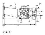
- Fig. 4 and Fig. 5 show, on an enlarged scale, the overall collecting pipe 18 and a portion of the connecting pipe 22 shown in Fig. 2 and Fig. 3.
- the collecting pipe 18 is made of cast iron, thin plates or lost wax (titanium alloy). It is connected to the exhaust pipes 16 by securing means such as bolts and to the connecting pipe 22 by joining means such as welding.
- the collecting pipe 18 has a housing 60 with exhaust passages formed inside.
- a schematic sectional view of the housing 60 is shown in Fig. 6.
- the housing 60 can be divided in the direction along exhaust flow into three parts: a front-end portion A, a middle portion B and a rear-end portion C, in terms of the number of the exhaust passages in the housing.
- the front-end portion A has four exhaust passages A1 to A4 in line in the lateral direction of the vehicle (in the direction along a crankshaft of the engine) defined by partitions 43 and a partition plate 44.
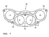
- the housing is a member of a hollow shape having the partitions 43 to define the exhaust passages A1 to A4, as is clear from Fig. 7 which shows the housing 60 as viewed from the front.
- the front-end portion A is formed with a flange 66, at the edge, for connecting the exhaust pipes.
- the exhaust passages A1 to A4 of the front-end portion A are connected to the exhaust pipes 16a to 16d, respectively, and formed next to each other and generally in parallel.
- the exhaust passages A1 to A4 are also formed generally in a V-shape as a whole, as shown in Fig. 7.
- the middle portion B has two exhaust passages B1, B2 in line in the lateral direction of the vehicle defined by the partition wall 44.
- the exhaust passage B1 is a secondary exhaust passage collecting the exhaust passages A1, A2 of the front-end portion.
- the exhaust passage B2 is a secondary exhaust passage collecting the exhaust passages A3, A4 of the front-end portion.
- the exhaust passages of the middle portion B each have a tapered portion 68 in profile at the outer periphery of the housing. The tapered portion is formed in a sloping manner so as to be gradually reduced in inside diameter of the housing 60 in the downstream direction of exhaust flow.
- the partition plate 44 extends from the front-end portion A to the vicinity of the rear end of the rear end portion C of the housing 60 along the center line of the housing 60, as shown in Fig. 6.
- the partition plate extends in the direction perpendicular to the surface of Fig. 6 and is formed integrally with the inner wall of the housing.
- the exhaust passage in the housing 60 is divided into the two exhaust passages B1, B2 in the region including the partition plate 44.
- the two exhaust passages finally join together between the rear end of the partition plate 44 and the rear end of the housing (in the region of the rear-end portion C of Fig. 6) into one, which is in turn connected to the connecting pipe 22 extending downstream (see Fig. 4 and Fig. 5).
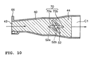
- the partition plate 44 is formed with a notch 70 required to permit an exhaust control valve 52, which will be described later, to pass through to be provided in the housing.
- the notch 70 includes a circular hole 70a and an extended portion 70b extending from a portion of the hole 70 in a direction across its diameter.
- the exhaust control means is disposed in the middle portion B of the housing.
- the housing 60 in the region of the middle portion B is formed with an opening 72 for removing the exhaust control valve 52 from the housing, as shown in Fig. 6, Fig. 8 and Fig. 9.
- the region surrounding the opening is configured as a boss slightly projecting outward of the housing to mount a control valve unit.
- the outer periphery edge, opposite the opening 72, of the housing 60 is integrally formed with a boss portion 74 protruding outward of the housing to support an end of the exhaust control valve 52.
- the boss portion 74 is formed to project to the right with respect to the moving direction of the body.
- the rear-end portion C is provided with no partition 43 or partition plate 44, as shown in Fig. 6, and formed with a single exhaust passage C1. Since the housing 60 of the collecting pipe 18 is configured in such a manner as described, the flow of exhaust gas discharged from the engine 10 is directed to the collecting pipe 18 through the exhaust pipes 16a to 16d, runs through the exhaust passages A1 to A4 of the front-end portion A inside the collecting pipe 18 and then collected by the two exhaust passages B1, 82 of the middle portion B, as indicated in Fig. 6 by the arrow. The exhaust gas collected by the two exhaust passages B1, B2 is then collected by the single exhaust passage C1 of the rear end portion C and directed to the silencer 20 through the connecting pipe 22.
- the exhaust control means 40 will be further described below.
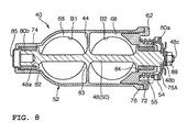
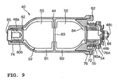
- Fig. 8 and Fig. 9 are sectional views taken along line B-C of Fig. 4.
- the exhaust control means includes the exhaust control valve 52 as a main component, as shown in these drawings.
- the control valve device has a valve seat 62 secured to the boss portion 76 of the housing 60, a shaft 48 passing through the exhaust collecting pipe (the region B, see Fig. 6), and a rotor blade 50 provided on the shaft 48.
- the components of the exhaust control valve 52 are assembled beforehand into a unit.
- the control valve unit is mounted into the exhaust collecting pipe in a way such that the valve seat 62 is secured with bolts 64 fitted in screw holes formed in the valve seat 62 and the region surrounding the opening 72.
- the valve seat 62 at the central portion has a boss portion 76A protruding outward of the housing 60.
- the boss portion 76A has a mechanism for supporting the shaft 48 of the exhaust control valve 52 for free rotational movement. More specifically, the boss portion 76A is provided with a bearing 80a, in the inner peripheral region. The bearing 80a supports the shaft 48 for free rotational movement.
- the exhaust control valve 52 has a pulley 54 as a rotating member fixed to an end of the shaft 48 and rotatable about the axis of the shaft 48.
- a belt 56 (see Fig. 1 and Fig. 5) is routed around the pulley and connected to a driving device 58 (see Fig. 1) for endlessly driving the belt 56.
- the driving device 58 is a motor, such as a pulse motor, as rotation means adapted to control the rotation angle of the rotor blade.
- the belt 56 is guided from the exhaust control means 40 below the engine to the driving device 58 above the exhaust control means 40 through guides 59a, 59b (see Fig. 5), as shown in Fig. 1.
- the shaft 48 of the exhaust control valve 52 is integrally provided with pressure receiving plates 82 to 84 projecting in the direction of the radius of the shaft 48, at the ends and the middle region, as shown in Fig. 8 and Fig. 9, and Fig. 11 and Fig. 12.
- the ends of the shaft has radially projecting shaft end portions 48a, 48b.
- the shaft end portions are each formed in a circular shape in section.
- the shaft end portion 48a at the opposite end of the shaft from the valve seat 62 is received in the boss portion 74 of the housing 60 via the bearing 80b, for free rotational movement.
- Reference numeral 85 denotes a cover for covering the shaft end portion 48a.
- a threaded shaft 48c projects from the shaft end portion 48b in the direction along its axis.
- the pulley 54 is inserted on the threaded shaft 48c and fastened to the threaded shaft 48c with a nut 88, as shown in Fig. 8 and Fig. 9.
- the driving mechanism such as a pulse motor permits the shaft 48 to rotate together with the pulley 54 by a controlled angle via the foregoing belt.
- Reference numeral 55 denotes a coil spring which presses the pulley 54 against the shaft 48.
- the coil spring provides improved sealing between the bearing 80a and the pressure receiving plate 84.
- the coil spring 55 is seated in an accommodation hole formed in the valve seat 62. One end of the coil spring 55 is in contact with the valve seat 62, and the other, with the pulley.
- the pressure receiving plates 82 to 84 define the exhaust passages.
- Fig. 13 is a sectional view taken along line A-A of Fig. 3.
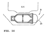
- Fig. 14 is a sectional view taken along line B-B of Fig. 3.
- the front-end portion A and the middle portion B including the exhaust control means 40 of the collecting pipe 18 are positioned below the engine, and the cowling 34 is positioned below the collecting pipe 18, at the bottom, as shown by phantom lines.
- the distance from the ground surface to the bottom of the cowling 34 shown by phantom lines equals vehicle's ground clearance.
- the exhaust system of the invention is adapted such that the area of the exhaust passages is controlled by the single exhaust control valve 52, thereby reducing the number of parts. Therefore, sufficiency is provided in any of vehicle's ground clearance, the size of an oil pan, and the rate of turn and layout flexibility is increased, when the exhaust control means 40 is disposed below the engine in the central portion of the body (see Fig. 14).
- the exhaust valve is mounted into the housing 60 in the following steps. As shown in Fig. 8, the shaft 48, rotor blade 50, bearing 80a, valve seat 62, coil spring 55, pulley 54 and nut 88 are assembled together beforehand into a unit. When this unit is mounted into the housing 60, the shaft 48 is first inserted in the circular opening 70a formed in the housing, with the rotor blade and the extended portion 70b shown in Fig. 10 aligned with each other. Then, an end of the shaft is received in the bearing 80b disposed in the boss portion 74 of the housing, for free rotational movement, and the other end, in the boss portion 76 for free rotational movement.
- FIG. 8 shows when the exhaust control valve 52 is fully opened to the exhaust passages (in parallel with exhaust flow).
- the exhaust control valve is fully closed to the exhaust passages, as shown in Fig. 9.
- the rotor blade 50 of the exhaust control valve is rotationally moved clockwise as shown in Fig. 10.
- the exhaust control valve 52 when positioned between the fully opened position 52a and the fully closed position 52b is shown by solid lines.
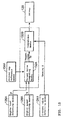
- Fig. 15 is a functional block diagram of a control circuit configuring a portion of the exhaust control means.
- the control circuit includes a microcomputer, a sensor, the foregoing pulse motor and a pulse motor driver.
- the microcomputer includes a control memory and a central processing unit.
- the control circuit has engine load detecting means 126A, engine speed detecting means 128A, control map reference means 134A, target value computing means 132A, current value detecting means 124A and comparison means 132B.
- the engine speed detecting means 128A detects engine speed N.
- the control map reference means 134A stores a plurality of control patterns of the exhaust control valve 52.
- the target value computing means 132A computes a target value of an exhaust control valve 52 opening ⁇ in relation to the engine speed, based on the optimal control pattern.
- the current value detecting means 124A detects a current value of the exhaust control valve 52 opening ⁇ .
- the comparison means 132B compares the target value and the current value.
- the output from the comparison means 132B is supplied to a motor driving circuit 138. This control circuit allows feedback control of the exhaust control valve opening. The valve opening can be detected and controlled based on an output value from a pulse motor encoder.
- Fig. 16 is a schematic diagram showing an example of a motorcycle engine with the exhaust control circuit.
- the exhaust pipes 16a to 16d are each connected to an exhaust opening of an exhaust valve 104.
- the downstream ends of the exhaust pipes are connected to the collecting pipe 18.
- the collecting pipe 18 is provided with the exhaust control valve 52.
- the exhaust control valve 52 When the exhaust control valve 52 is in the fully closed position (see Fig. 9), the area of the exhaust passages is reduced to about one-fourth of the total area of the exhaust passages.
- the exhaust control valve 52 opening is set by a pulse motor (stepping motor) 122 as a driving device via the foregoing belt 56.
- the engine load detecting means denoted by reference numeral 126A is a knock sensor, for example.
- the CPU 132 controls the exhaust control valve 52 opening, that is, the area of the exhaust passages in accordance with the engine conditions detected by those sensors, in a way such that engine operation produces optimal output characteristics. More specifically, the optimal control patterns of the exhaust control valve 52 in accordance with the engine conditions are stored as control maps in a ROM 134 (control map reference means 134A) beforehand.
- the target value computing means 132A achieved by the CPU 132 selects the optimal control pattern in accordance with the engine conditions such as the engine speed N.
- the target value computing means 132A then computes a target rotational angle value ⁇ 0 of the motor, which corresponds to the valve opening, to achieve the optimal area of the exhaust passages to the current engine conditions, based on the selected control pattern.
- the other indicators of the engine conditions include a detection value by an oxygen sensor 126 shown in Fig. 16.
- Reference numeral 102 denotes an intake valve.
- the pulley 54 is fixed to the threaded shaft 48c of the shaft end portion 48b of the valve shaft. Therefore, the rotation of the pulley by the motor 122 via the belt 56 allows control of the area of the exhaust passages.
- the exhaust control valve 52 is controlled in the closing direction when the engine is running in a speed range with low volumetric efficiency, while controlled in the opening direction when the engine is running in the other speed ranges, based on the engine speed detected by the speed sensor 128.
- the control circuit causes the motor 122 to drive the exhaust control valve 52 to be closed when the engine is running in the low-speed range.
- Fig. 17 The relation between engine speed and an exhaust control valve 52 opening is shown in Fig. 17.
- the exhaust control valve 52 is fully closed when the exhaust control valve 52 opening is zero degree, while the exhaust control valve 52 is fully opened when the exhaust control valve 52 opening is 90 degrees.
- the exhaust control valve 52 opening is, however, controlled when the engine is running in the low-speed range, as shown by broken lines in Fig. 17, in order to prevent a sharp increase in torque immediately after an engine start.
- Fig. 18 shows the relation between engine speed and torque when the exhaust control valve 52 opening is controlled in accordance with control characteristics of Fig. 17.
- solid line a shows when the amount of exhaust flow is controlled by the exhaust system of the invention.
- broken line b shows when no amount of exhaust flow is controlled, for comparison.
- an exhaust system wherein a front end portion of a collecting pipe compri ses a larger number of exhaust passages than a middle portion thereof and/or in that a middle portion of a collecting pipe comprises a larger number of exhaust passages than a rear-end portion thereof.
- an exhaust system wherein an exhaust control means is provided in a portion of a collecting pipe that comprises fewer separate exhaust passages than a portion thereof connected to exhaust pipes attachable to an engine block, and comprises more exhaust passages than a portion thereof connected to a silencer.
- an exhaust system for a multi-cylinder engine having a plurality of exhaust pipes with one ends connected to exhaust openings of a multi-cylinder engine, and a collecting pipe connected to the other ends of the exhaust pipes for collecting exhaust introduced from the exhaust pipes and directing it to a silencer.
- the collecting pipe has a front-end portion communicated to exhaust passages of the exhaust pipes, a middle portion for collecting the exhaust introduced from the front-end portion, and a rear-end portion for further collecting the exhaust introduced from the middle portion.
- the middle portion is provided with exhaust control means for controlling the area of the exhaust passages in accordance with engine speed.
Landscapes
- Engineering & Computer Science (AREA)
- Chemical & Material Sciences (AREA)
- Combustion & Propulsion (AREA)
- Mechanical Engineering (AREA)
- General Engineering & Computer Science (AREA)
- Exhaust Silencers (AREA)
- Control Of Throttle Valves Provided In The Intake System Or In The Exhaust System (AREA)
- Characterised By The Charging Evacuation (AREA)
Abstract
Description
- The invention relates to an exhaust system for a multi-cylinder engine having a plurality of exhaust pipes with one end connectable to exhaust openings of the multi-cylinder engine and other ends of the exhaust pipes connected to a collecting pipe configured to collect exhaust introduced from the exhaust pipes and directing it to a silencer, a multi-cylinder engine having a crankcase and a plurality of cylinders with exhaust openings, and a straddle-type vehicle comprising a multi-cylinder engine and an exhaust system for the multi-cylinder engine.
- Generally, in a four-stroke engine, a two-stroke engine and the like, it is known that opening and closing of an exhaust valve introduces exhaust into an exhaust pipe intermittently, where an inertia effect and a pulsation effect of the exhaust are produced. These effects (hereinafter called a "dynamic effect") change in accordance with engine conditions (mainly engine speed).
- Therefore, maximizing the dynamic effect to increase volumetric efficiency of the engine at a certain speed significantly reduces the volumetric efficiency at the other speeds due to the dynamic effect working in reverse. Thus, in the case that the features of an exhaust system (the length, diameter and the like of the exhaust pipe) are made so that the optimal dynamic effect is produced in the high-speed range, a problem arises of the significant reduction in torque (drop in torque) in the middle-speed range.
- Meanwhile, various proposals have been made to improve engine output in a way such that an exhaust control valve adapted to change the area of the exhaust passage is provided in the exhaust pipe, and the exhaust control valve is closed to reduce the area of the exhaust passage and eliminate the dynamic effect in the middle- and low-speed ranges with low volumetric efficiency.
- For example, JP-A-Sho 64-15428 discloses an exhaust control system having two sets of exhaust control valves disposed non-coaxially and generally in parallel with each other at the ends of four exhaust pipes, and an interlock mechanism provided at the ends of shafts of the exhaust control valves. When exhaust pressure is exerted on the exhaust control valves, rotational forces produced by the shafts of the exhaust control valves are cancelled through the interlock mechanism, thereby providing reduced load on a motor or the like. This allows reduction of power produced by the motor or the like for driving the exhaust control valves, thereby effecting its size reduction.
- JP-A-2002-138828 discloses an exhaust control system for a motorcycle having four exhaust pipes collected into two and then into one, a connecting pipe connected to the front end of a silencer, and a valve mechanism (exhaust control valve) adapted to change the area of an exhaust passage in the connecting pipe, for controlling exhaust pulsation.
- In the exhaust control system having the two sets of exhaust control valves disposed non-coaxially and generally in parallel with each other at the downstream ends of the exhaust pipes, the exhaust control valves are arranged at the ends of the four exhaust pipes, generally in a shape of a square with a cross inside as viewed radially in section. The area of the exhaust passages of the four exhaust pipes is thus controlled by the two sets of exhaust control valves. Therefore, the housing for containing the exhaust control valves is increased in size, resulting in the increased number of parts.
- In the exhaust system having the valve mechanism (exhaust control valve) provided forwardly of the silencer, layout flexibility is improved; however, since the valve mechanism (exhaust control valve) is positioned away from the engine, no exhaust gas pressure enough to obtain the dynamic effect is provided, which is left to be improved for further improvement in performance.
- In view of the foregoing, it is, therefore, an object of the invention to provide an exhaust system for a multi-cylinder engine capable of reducing the number of parts, increasing layout flexibility in particular when the exhaust control valve is disposed below the engine, and/or improving engine performance in the low- and middle-speed ranges.
- Further, it is an object of the invention to improve a multi-cylinder engine of the above kind to have an improved performance in the low and middle speed ranges.
- Moreover, it is an object of the invention to provide an improved straddle-type vehicle with an improved exhaust system.
- For an exhaust system of the above kind, this object is solved in an inventive manner in that the collecting pipe comprises: a front-end portion communicated to exhaust passages of the exhaust pipes; a middle portion configured to collect the exhaust introduced from the front-end portion; and a rear-end portion configured to further collect the exhaust introduced from the middle portion, wherein the middle portion is provided with an exhaust control means configured to control the area of the exhaust passages in accordance with engine conditions.
- According to the invention, exhaust from the plurality of exhaust pipes is collected together and then the amount of exhaust flow is controlled. Therefore, the number of parts of the exhaust control portion can be reduced, as compared with when the amount of exhaust flow is controlled at the ends of the exhaust pipes as in the prior art. Further, the area of the exhaust passages is controlled immediately before the exhaust pipe is collected into one. Therefore, the amount of exhaust flow can be controlled at a position where enough exhaust gas pressure is provided, as compared with when exhaust flow is collected into one and then controlled in the amount as in the prior art.
- The exhaust system of the invention allows reduction in the number of parts of the exhaust control portion, as well as arrangement in reduced space in the vehicle. Therefore, vehicle's ground clearance, the size of an oil pan, and the rate of turn are sufficiently provided. Further, engine performance can be improved in the low- and middle-speed ranges.
- According to a preferred embodiment, the front-end portion is formed with at least four exhaust passages. It is further preferred that the middle portion is formed with at least two exhaust passages. Moreover, preferably the rear-end portion is formed with a single exhaust passage. Such kinds of configurations allow an arbitrary number of exhaust passages to be formed in the collecting pipe. Thus, the exhaust control system can be configured to have the exhaust passage of a 4-into-2-into-1 type or a 6-into-3-into-1 type, for example.
- According to a further embodiment, the exhaust control means has an exhaust control valve which can be controlled in opening. Controlling the valve opening can change the area of the exhaust passages. Such a configuration requires no interlock mechanism as in the prior art and allows the area of the exhaust passages to be controlled with a relatively simple construction.
- Preferably, the amount of exhaust flow is controlled in the middle portion of the collecting pipe. Therefore, the area of the exhaust passages can be controlled by the single exhaust control valve, and the amount of exhaust flow can be controlled at a position where enough exhaust gas pressure is provided.
- It is further preferred that the exhaust control means has detection means for detecting engine conditions (engine speed, for example), control map reference means for storing control patterns of the exhaust control valve in accordance with the output from the detection means, and target value computing means for computing a target value of an exhaust control valve opening in relation to the engine conditions, based on the control pattern read from the control map reference means. The exhaust control means may be further provided with current value detecting means for determining a current value of the exhaust control valve opening, and comparison and control means for controlling driving means of the exhaust control valve to bring the current value closer to the target value. This configuration provides the most desirable output characteristics in accordance with change in engine speed and allows appropriate control of the output characteristics.
- For a multi-cylinder engine, the above object is solved in an inventive manner in that the exhaust openings are connected to an exhaust system according to at least one of the
claims 1 to 8. - Thereby, the engine performance can be improved in particular in the low and middle speed ranges.
- For a straddle-type vehicle, the above object is solved by the features of
claim 10. - Further preferred embodiments are subject to the subclaims.
- In the following, the invention will be described in greater detail by means of an embodiment thereof with reference to the accompanying drawings, wherein:
- Fig. 1
- shows an example of a straddle-type vehicle in the embodiment of a
motorcycle 2 with an
exhaust system 1; - Fig. 2
- is a left side view of the
exhaust system 1; - Fig. 3
- is a plan view of the
exhaust system 1; - Fig. 4
- shows, on an enlarged scale, an
overall collecting pipe 18 and a portion of a connectingpipe 22 shown in Fig. 2 and Fig. 3; - Fig. 5
- shows, on an enlarged scale, the
overall collecting pipe 18 and a portion of the connectingpipe 22 shown in Fig. 2 and Fig. 3; - Fig. 6
- is a horizontal sectional view of a
housing 60 of Fig. 4; - Fig. 7
- shows the
housing 60 as viewed from the front; - Fig. 8
- is a sectional view taken along line B-C of Fig. 4, showing when an
exhaust control valve 52 is fully opened; - Fig. 9
- is a sectional view taken along line B-C of Fig. 4, showing when the
exhaust control valve 52 is fully closed; - Fig. 10
- is a sectional view taken along line D-D of Fig 4;
- Fig. 11
- is a plan view of the
exhaust control valve 52 for explaining its external appearance; - Fig. 12
- is a front view of the
exhaust control valve 52 for explaining its external appearance; - Fig. 13
- is a sectional view taken along line A-A of Fig. 3, illustrating the motorcycle body with the exhaust system;
- Fig. 14
- is a sectional view taken along line B-B of Fig. 3, illustrating the motorcycle body with the exhaust system;
- Fig. 15
- is a functional block diagram of an exhaust control means 40;
- Fig. 16
- is a schematic diagram showing an example of a motorcycle engine with the exhaust system of the invention provided with the exhaust control means 40;
- Fig. 17
- illustrates the relation between engine speed and an
exhaust control valve 52 opening; and - Fig. 18
- illustrates the relation between engine speed and torque.
- Fig. 1 shows an example of one of straddle-type vehicles, a motorcycle 2, with an
exhaust system 1 for a multi-cylinder engine (hereinafter, in some cases, simply referred to as an "exhaust system"). - As shown in Fig. 1, the motorcycle 2 has a
front wheel 24, a steeringhandlebar 26, arear wheel 28, acover 30 for covering an intake cleaner and a fuel tank, a driver'sseat 32 and acowling 34. A four-stroke, four-cylinder engine 10 is located in the central portion of the body. Theengine 10 has acylinder 14 extending obliquely upward toward the front from a crankcase 12. Theexhaust system 1 extends from thecylinder 14 at the front side of the vehicle and is routed along under theengine 10. - An overall view of the
exhaust system 1 is shown in Fig. 2 and Fig. 3. Fig. 2 is a left side view of theexhaust system 1 with respect to a running direction of the vehicle. Fig. 3 is a plan view of theexhaust system 1. Theexhaust system 1 has a plurality ofexhaust pipes 16a to 16d with one ends connected to exhaust openings of the multi-cylinder engine 10 (see Fig. 1), and a collectingpipe 18 connected to the other ends of theexhaust pipes 16a to 16d for collecting the exhaust pipes. The collectingpipe 18 is connected to a connectingpipe 22 extending downstream and connected to asilencer 20. The collectingpipe 18 is provided with an exhaust control means (exhaust control valve) 40 for controlling the area of exhaust passages. A protecting cap of design 23 (See Fig. 3) is attached to the exhaust control means 40 to cover its end. - Fig. 4 and Fig. 5 show, on an enlarged scale, the
overall collecting pipe 18 and a portion of the connectingpipe 22 shown in Fig. 2 and Fig. 3. The collectingpipe 18 is made of cast iron, thin plates or lost wax (titanium alloy). It is connected to theexhaust pipes 16 by securing means such as bolts and to the connectingpipe 22 by joining means such as welding. - The collecting
pipe 18 has ahousing 60 with exhaust passages formed inside. A schematic sectional view of thehousing 60 is shown in Fig. 6. Thehousing 60 can be divided in the direction along exhaust flow into three parts: a front-end portion A, a middle portion B and a rear-end portion C, in terms of the number of the exhaust passages in the housing. - The front-end portion A has four exhaust passages A1 to A4 in line in the lateral direction of the vehicle (in the direction along a crankshaft of the engine) defined by
partitions 43 and apartition plate 44. The housing is a member of a hollow shape having thepartitions 43 to define the exhaust passages A1 to A4, as is clear from Fig. 7 which shows thehousing 60 as viewed from the front. The front-end portion A is formed with aflange 66, at the edge, for connecting the exhaust pipes. The exhaust passages A1 to A4 of the front-end portion A are connected to theexhaust pipes 16a to 16d, respectively, and formed next to each other and generally in parallel. The exhaust passages A1 to A4 are also formed generally in a V-shape as a whole, as shown in Fig. 7. - As shown in Fig. 6, the middle portion B has two exhaust passages B1, B2 in line in the lateral direction of the vehicle defined by the
partition wall 44. The exhaust passage B1 is a secondary exhaust passage collecting the exhaust passages A1, A2 of the front-end portion. The exhaust passage B2 is a secondary exhaust passage collecting the exhaust passages A3, A4 of the front-end portion. The exhaust passages of the middle portion B each have a taperedportion 68 in profile at the outer periphery of the housing. The tapered portion is formed in a sloping manner so as to be gradually reduced in inside diameter of thehousing 60 in the downstream direction of exhaust flow. - The
partition plate 44 extends from the front-end portion A to the vicinity of the rear end of the rear end portion C of thehousing 60 along the center line of thehousing 60, as shown in Fig. 6. The partition plate extends in the direction perpendicular to the surface of Fig. 6 and is formed integrally with the inner wall of the housing. The exhaust passage in thehousing 60 is divided into the two exhaust passages B1, B2 in the region including thepartition plate 44. The two exhaust passages finally join together between the rear end of thepartition plate 44 and the rear end of the housing (in the region of the rear-end portion C of Fig. 6) into one, which is in turn connected to the connectingpipe 22 extending downstream (see Fig. 4 and Fig. 5). - As shown in Fig. 6 and Fig. 10, the
partition plate 44 is formed with anotch 70 required to permit anexhaust control valve 52, which will be described later, to pass through to be provided in the housing. Thenotch 70 includes acircular hole 70a and anextended portion 70b extending from a portion of thehole 70 in a direction across its diameter. - The exhaust control means is disposed in the middle portion B of the housing. The
housing 60 in the region of the middle portion B is formed with anopening 72 for removing theexhaust control valve 52 from the housing, as shown in Fig. 6, Fig. 8 and Fig. 9. The region surrounding the opening is configured as a boss slightly projecting outward of the housing to mount a control valve unit. The outer periphery edge, opposite theopening 72, of thehousing 60 is integrally formed with aboss portion 74 protruding outward of the housing to support an end of theexhaust control valve 52. Theboss portion 74 is formed to project to the right with respect to the moving direction of the body. - The rear-end portion C is provided with no
partition 43 orpartition plate 44, as shown in Fig. 6, and formed with a single exhaust passage C1. Since thehousing 60 of the collectingpipe 18 is configured in such a manner as described, the flow of exhaust gas discharged from theengine 10 is directed to the collectingpipe 18 through theexhaust pipes 16a to 16d, runs through the exhaust passages A1 to A4 of the front-end portion A inside the collectingpipe 18 and then collected by the two exhaust passages B1, 82 of the middle portion B, as indicated in Fig. 6 by the arrow. The exhaust gas collected by the two exhaust passages B1, B2 is then collected by the single exhaust passage C1 of the rear end portion C and directed to thesilencer 20 through the connectingpipe 22. - The exhaust control means 40 will be further described below. Fig. 8 and Fig. 9 are sectional views taken along line B-C of Fig. 4. The exhaust control means includes the
exhaust control valve 52 as a main component, as shown in these drawings. The control valve device has avalve seat 62 secured to theboss portion 76 of thehousing 60, ashaft 48 passing through the exhaust collecting pipe (the region B, see Fig. 6), and arotor blade 50 provided on theshaft 48. The components of theexhaust control valve 52 are assembled beforehand into a unit. The control valve unit is mounted into the exhaust collecting pipe in a way such that thevalve seat 62 is secured withbolts 64 fitted in screw holes formed in thevalve seat 62 and the region surrounding theopening 72. - The
valve seat 62 at the central portion has aboss portion 76A protruding outward of thehousing 60. Theboss portion 76A has a mechanism for supporting theshaft 48 of theexhaust control valve 52 for free rotational movement. More specifically, theboss portion 76A is provided with abearing 80a, in the inner peripheral region. Thebearing 80a supports theshaft 48 for free rotational movement. When theshaft 48 is rotationally moved, therotor blade 50 fixed thereon is rotationally moved together by a specified angle with respect to the exhaust passages and then stopped so that the exhaust passages are changed in area. - The
exhaust control valve 52 has apulley 54 as a rotating member fixed to an end of theshaft 48 and rotatable about the axis of theshaft 48. A belt 56 (see Fig. 1 and Fig. 5) is routed around the pulley and connected to a driving device 58 (see Fig. 1) for endlessly driving thebelt 56. The drivingdevice 58 is a motor, such as a pulse motor, as rotation means adapted to control the rotation angle of the rotor blade. Thebelt 56 is guided from the exhaust control means 40 below the engine to the drivingdevice 58 above the exhaust control means 40 throughguides - The
shaft 48 of theexhaust control valve 52 is integrally provided withpressure receiving plates 82 to 84 projecting in the direction of the radius of theshaft 48, at the ends and the middle region, as shown in Fig. 8 and Fig. 9, and Fig. 11 and Fig. 12. The ends of the shaft has radially projectingshaft end portions shaft end portion 48a at the opposite end of the shaft from thevalve seat 62 is received in theboss portion 74 of thehousing 60 via thebearing 80b, for free rotational movement.Reference numeral 85 denotes a cover for covering theshaft end portion 48a. - As shown in Fig. 11 and Fig. 12, a threaded
shaft 48c projects from theshaft end portion 48b in the direction along its axis. Thepulley 54 is inserted on the threadedshaft 48c and fastened to the threadedshaft 48c with anut 88, as shown in Fig. 8 and Fig. 9. The driving mechanism such as a pulse motor permits theshaft 48 to rotate together with thepulley 54 by a controlled angle via the foregoing belt.Reference numeral 55 denotes a coil spring which presses thepulley 54 against theshaft 48. The coil spring provides improved sealing between thebearing 80a and thepressure receiving plate 84. Thecoil spring 55 is seated in an accommodation hole formed in thevalve seat 62. One end of thecoil spring 55 is in contact with thevalve seat 62, and the other, with the pulley. Thepressure receiving plates 82 to 84 define the exhaust passages. - Fig. 13 is a sectional view taken along line A-A of Fig. 3. Fig. 14 is a sectional view taken along line B-B of Fig. 3. In these drawings, the front-end portion A and the middle portion B including the exhaust control means 40 of the collecting
pipe 18 are positioned below the engine, and thecowling 34 is positioned below the collectingpipe 18, at the bottom, as shown by phantom lines. The distance from the ground surface to the bottom of thecowling 34 shown by phantom lines equals vehicle's ground clearance. The exhaust system of the invention is adapted such that the area of the exhaust passages is controlled by the singleexhaust control valve 52, thereby reducing the number of parts. Therefore, sufficiency is provided in any of vehicle's ground clearance, the size of an oil pan, and the rate of turn and layout flexibility is increased, when the exhaust control means 40 is disposed below the engine in the central portion of the body (see Fig. 14). - The exhaust valve is mounted into the
housing 60 in the following steps. As shown in Fig. 8, theshaft 48,rotor blade 50, bearing 80a,valve seat 62,coil spring 55,pulley 54 andnut 88 are assembled together beforehand into a unit. When this unit is mounted into thehousing 60, theshaft 48 is first inserted in thecircular opening 70a formed in the housing, with the rotor blade and theextended portion 70b shown in Fig. 10 aligned with each other. Then, an end of the shaft is received in thebearing 80b disposed in theboss portion 74 of the housing, for free rotational movement, and the other end, in theboss portion 76 for free rotational movement. - Next will be described the rotational direction (opening direction) of the
exhaust control valve 52. Fig. 8 shows when theexhaust control valve 52 is fully opened to the exhaust passages (in parallel with exhaust flow). When theshaft 48 is rotationally moved by 90 degrees from the illustrated position, the exhaust control valve is fully closed to the exhaust passages, as shown in Fig. 9. When the exhaust control valve is displaced from the fully opened position to the fully closed position, therotor blade 50 of the exhaust control valve is rotationally moved clockwise as shown in Fig. 10. In Fig. 10, theexhaust control valve 52 when positioned between the fully openedposition 52a and the fullyclosed position 52b is shown by solid lines. - When the
exhaust control valve 52 is in the fully opened position (denoted byreference numeral 52a in Fig. 10), exhaust flows in the direction indicated by the arrow in Fig. 10 almost smoothly through a gap formed between therotor blade 50 of the exhaust valve and thehousing 60. When theexhaust control valve 52 is in the fully closed position (denoted byreference numeral 52b in Fig. 10), exhaust flow strikes against therotor blade 50, which causes a negative pressure to be exerted in the direction opposite to the arrow, in accordance with anexhaust control valve 52 opening. When the exhaust control valve is in the fullyclosed position 52b, however, there is a gap left between the exhaust control valve and thehousing 60, which is large enough for exhaust gas to pass through. - Next will be described control of the
exhaust control valve 52 opening. Fig. 15 is a functional block diagram of a control circuit configuring a portion of the exhaust control means. The control circuit includes a microcomputer, a sensor, the foregoing pulse motor and a pulse motor driver. The microcomputer includes a control memory and a central processing unit. - The control circuit has engine load detecting means 126A, engine speed detecting means 128A, control map reference means 134A, target value computing means 132A, current value detecting means 124A and comparison means 132B. The engine
speed detecting means 128A detects engine speed N. The control map reference means 134A stores a plurality of control patterns of theexhaust control valve 52. The target value computing means 132A computes a target value of anexhaust control valve 52 opening in relation to the engine speed, based on the optimal control pattern. The currentvalue detecting means 124A detects a current value of theexhaust control valve 52 opening . The comparison means 132B compares the target value and the current value. The output from the comparison means 132B is supplied to amotor driving circuit 138. This control circuit allows feedback control of the exhaust control valve opening. The valve opening can be detected and controlled based on an output value from a pulse motor encoder. - Fig. 16 is a schematic diagram showing an example of a motorcycle engine with the exhaust control circuit. The
exhaust pipes 16a to 16d are each connected to an exhaust opening of anexhaust valve 104. The downstream ends of the exhaust pipes are connected to the collectingpipe 18. The collectingpipe 18 is provided with theexhaust control valve 52. - When the
exhaust control valve 52 is in the fully closed position (see Fig. 9), the area of the exhaust passages is reduced to about one-fourth of the total area of the exhaust passages. Theexhaust control valve 52 opening is set by a pulse motor (stepping motor) 122 as a driving device via the foregoingbelt 56. - The engine speed N detected by a speed sensor 128, as well as a pulse value corresponding to the
exhaust control valve 52 opening detected by arotary encoder 124 of the pulse motor, is inputted to thecentral processing unit 132 via an A/D converter and aninterface 130. The engine load detecting means denoted byreference numeral 126A is a knock sensor, for example. - The
CPU 132 controls theexhaust control valve 52 opening, that is, the area of the exhaust passages in accordance with the engine conditions detected by those sensors, in a way such that engine operation produces optimal output characteristics. More specifically, the optimal control patterns of theexhaust control valve 52 in accordance with the engine conditions are stored as control maps in a ROM 134 (control map reference means 134A) beforehand. The target value computing means 132A achieved by theCPU 132 selects the optimal control pattern in accordance with the engine conditions such as the engine speed N. The target value computing means 132A then computes a target rotational angle value 0 of the motor, which corresponds to the valve opening, to achieve the optimal area of the exhaust passages to the current engine conditions, based on the selected control pattern. The other indicators of the engine conditions include a detection value by anoxygen sensor 126 shown in Fig. 16.Reference numeral 102 denotes an intake valve. - As shown in Fig. 8 and Fig. 9, the
pulley 54 is fixed to the threadedshaft 48c of theshaft end portion 48b of the valve shaft. Therefore, the rotation of the pulley by themotor 122 via thebelt 56 allows control of the area of the exhaust passages. For example, theexhaust control valve 52 is controlled in the closing direction when the engine is running in a speed range with low volumetric efficiency, while controlled in the opening direction when the engine is running in the other speed ranges, based on the engine speed detected by the speed sensor 128. Therefore, in the case that the diameter, length and the like of theexhaust pipe 16 are made so that volumetric efficiency of the engine is increased in the high-speed range, the control circuit causes themotor 122 to drive theexhaust control valve 52 to be closed when the engine is running in the low-speed range. - The relation between engine speed and an
exhaust control valve 52 opening is shown in Fig. 17. In Fig. 17, theexhaust control valve 52 is fully closed when theexhaust control valve 52 opening is zero degree, while theexhaust control valve 52 is fully opened when theexhaust control valve 52 opening is 90 degrees. Theexhaust control valve 52 opening is, however, controlled when the engine is running in the low-speed range, as shown by broken lines in Fig. 17, in order to prevent a sharp increase in torque immediately after an engine start. - Fig. 18 shows the relation between engine speed and torque when the
exhaust control valve 52 opening is controlled in accordance with control characteristics of Fig. 17. In Fig. 18, solid line a shows when the amount of exhaust flow is controlled by the exhaust system of the invention. Broken line b shows when no amount of exhaust flow is controlled, for comparison. As is clear from Fig. 18, according to the invention, when the amount of exhaust flow is controlled (a), the reduction in volumetric efficiency (drop in torque) can be restricted in the middle- and low-speed ranges, as compared with when no amount of exhaust flow is controlled (b). - The foregoing description has been made of the exhaust system having four, two and one exhaust passages provided for the front-end portion A, middle portion B and rear-end portion C of the collecting
pipe 18, respectively. The description, however, is also applied to the exhaust system having six, three and one exhaust passages provided by theadditional partition 43 andpartition plate 44. - According to an invention, as preferably described above, an exhaust system is provided, wherein a front end portion of a collecting pipe compri ses a larger number of exhaust passages than a middle portion thereof and/or in that a middle portion of a collecting pipe comprises a larger number of exhaust passages than a rear-end portion thereof.
- Further, according to an invention, as preferably described above, an exhaust system is provided, wherein an exhaust control means is provided in a portion of a collecting pipe that comprises fewer separate exhaust passages than a portion thereof connected to exhaust pipes attachable to an engine block, and comprises more exhaust passages than a portion thereof connected to a silencer.
- As further described above, in order to provide an exhaust system for a multi-cylinder engine capable of providing sufficiency in any of vehicle's ground clearance, the size of an oil pan, and the rate of turn and increasing layout flexibility, when an exhaust control valve is disposed below the engine in the central portion of the body, an exhaust system for a multi-cylinder engine is proposed having a plurality of exhaust pipes with one ends connected to exhaust openings of a multi-cylinder engine, and a collecting pipe connected to the other ends of the exhaust pipes for collecting exhaust introduced from the exhaust pipes and directing it to a silencer. The collecting pipe has a front-end portion communicated to exhaust passages of the exhaust pipes, a middle portion for collecting the exhaust introduced from the front-end portion, and a rear-end portion for further collecting the exhaust introduced from the middle portion. The middle portion is provided with exhaust control means for controlling the area of the exhaust passages in accordance with engine speed.
Claims (10)
- Exhaust system for a multi-cylinder engine (1) having a plurality of exhaust pipes (16a-d) with one end connectable to exhaust openings of the multi-cylinder engine, and other ends of the exhaust pipes (16a-d) connected to a collecting pipe (18) configured to collect exhaust introduced from the exhaust pipes (16a-d) and directing it to a silencer (20), characterized in that the collecting pipe (18) comprises:a front-end portion (A) communicated to exhaust passages of the exhaust pipes (16a-d);a middle portion (B) configured to collect the exhaust introduced from the front-end portion (A); anda rear-end portion (C) configured to further collect the exhaust introduced from the middle portion (B), wherein the middle portion (B) is provided with an exhaust control means (40) configured to control the area of the exhaust passages in accordance with engine conditions.
- Exhaust system according to claim 1, characterized in that the front end portion (A) comprises a larger number of exhaust passages (A1,A2,A3,A4) than the middle portion (B) and/or in that the middle portion (B) comprises a larger number of exhaust passages (B1,B2) than the rear-end portion (C).
- Exhaust system according to claim 1 or 2, characterized in that the exhaust control means (40) is provided in a portion (B) of the collecting pipe (18) that comprises fewer exhaust passages (B1,B2) than a portion (A) thereof connected to the exhaust pipes (16a-d) and comprises more exhaust passages (B1,B2) than a portion (C) thereof connected to the silencer (20).
- Exhaust system for a multi-cylinder engine (1) according to claim 1, characterized in that the front-end portion (A) is formed with at least four exhaust passages (A1,A2,A3,A4), and/or in that the middle portion (B) is formed with at least two exhaust passages (B1,B2), and/or in that the rear-end portion (C) is formed with a single exhaust passage (C1).
- Exhaust system for a multi-cylinder engine (1) according to at least one of claims 1 to 4, characterized in that the exhaust control means (40) has an exhaust control valve (52) adapted to change the area of the exhaust passages (B1,B2).
- Exhaust system for a multi-cylinder engine (1) according to claim 5, characterized in that the area of the exhaust passages is controlled by the exhaust control valve (52) being a single exhaust control valve.
- Exhaust system for a multi-cylinder engine (1) according to at least one of claims 1 to 6, characterized in that the exhaust control means (40) has:detection means (124,124A,126,126A,128A) for detecting engine conditions;control map reference means (134A) for storing control patterns of the exhaust control valve (52); andtarget value computing means (132A) for computing a target value (o) of an exhaust control valve opening in relation to the detection value of the engine conditions, based on the control pattern read from the control map reference means (134A).
- Exhaust system for a multi-cylinder engine according to at least one of claims 1 to 7, characterized in that the exhaust control means (40) is disposed below a crankcase (12,E/G) of the engine.
- Multi-cylinder engine having a crankcase (12) and a plurality of cylinders (14) with exhaust openings, characterized in that the exhaust openings are connected to an exhaust system (1) according to at least one of the claims 1 to 8.
- Straddle-type vehicle comprising a multi-cylinder engine (10) and an exhaust system (1) for the multi-cylinder engine (10), characterized in that the exhaust system (1) is configured according to at least one of claims 1 to 8.
Applications Claiming Priority (2)
| Application Number | Priority Date | Filing Date | Title |
|---|---|---|---|
| JP2003295804 | 2003-08-20 | ||
| JP2003295804A JP2005061375A (en) | 2003-08-20 | 2003-08-20 | Exhaust device for multi-cylinder engine and straddle-type vehicle equipped with the same |
Publications (2)
| Publication Number | Publication Date |
|---|---|
| EP1508678A2 true EP1508678A2 (en) | 2005-02-23 |
| EP1508678A3 EP1508678A3 (en) | 2009-03-04 |
Family
ID=34056226
Family Applications (1)
| Application Number | Title | Priority Date | Filing Date |
|---|---|---|---|
| EP04019835A Withdrawn EP1508678A3 (en) | 2003-08-20 | 2004-08-20 | Exhaust system for multi-cylinder engine, multi-cylinder engine and straddle-type vehicle |
Country Status (4)
| Country | Link |
|---|---|
| US (1) | US7171804B2 (en) |
| EP (1) | EP1508678A3 (en) |
| JP (1) | JP2005061375A (en) |
| CN (1) | CN100371568C (en) |
Cited By (2)
| Publication number | Priority date | Publication date | Assignee | Title |
|---|---|---|---|---|
| EP1847701A3 (en) * | 2006-04-20 | 2008-07-30 | Dr. Ing. h.c. F. Porsche Aktiengesellschaft | Intake manifold for an internal combustion engine |
| WO2014139501A1 (en) * | 2013-03-10 | 2014-09-18 | Kohlhage Automotive GmbH & Co. KG | Exhaust-gas system |
Families Citing this family (20)
| Publication number | Priority date | Publication date | Assignee | Title |
|---|---|---|---|---|
| JP4272029B2 (en) * | 2003-09-30 | 2009-06-03 | 本田技研工業株式会社 | Motorcycle exhaust control system |
| JP2006199175A (en) * | 2005-01-21 | 2006-08-03 | Yamaha Motor Co Ltd | Snowmobile |
| JP2006199176A (en) * | 2005-01-21 | 2006-08-03 | Yamaha Motor Co Ltd | Snowmobile exhaust system |
| JP2007046463A (en) * | 2005-08-05 | 2007-02-22 | Yamaha Motor Co Ltd | Exhaust system and engine apparatus and vehicle including the same |
| US7874149B2 (en) * | 2005-08-17 | 2011-01-25 | Kawasaki Jukogyo Kabushiki Kaisha | Exhaust apparatus for vehicle, and motorcycle having the same |
| JP2007198256A (en) * | 2006-01-26 | 2007-08-09 | Calsonic Kansei Corp | Exhaust manifold |
| US7814748B2 (en) * | 2006-05-05 | 2010-10-19 | Continental Automotive Canada, Inc. | Exhaust bypass valve remote linkage |
| JP4851890B2 (en) * | 2006-09-01 | 2012-01-11 | 本田技研工業株式会社 | Motorcycle exhaust system |
| JP4767183B2 (en) * | 2007-01-15 | 2011-09-07 | 川崎重工業株式会社 | Engine exhaust device |
| JP5015646B2 (en) * | 2007-03-30 | 2012-08-29 | 本田技研工業株式会社 | Exhaust system for motorcycles |
| JP2009241922A (en) * | 2007-12-28 | 2009-10-22 | Yamaha Motor Co Ltd | Saddle riding vehicle |
| JP2012036887A (en) * | 2010-07-13 | 2012-02-23 | Calsonic Kansei Corp | Exhaust control valve |
| JP5788704B2 (en) * | 2011-04-25 | 2015-10-07 | 本田技研工業株式会社 | Engine for saddle-ride type vehicles |
| US8695200B2 (en) * | 2011-12-19 | 2014-04-15 | Ford Global Technologies, Llc | Tether for tubes of an exhaust system joint |
| JP2013213411A (en) * | 2012-03-30 | 2013-10-17 | Honda Motor Co Ltd | Exhaust apparatus for internal combustion engine |
| DE102012103926B4 (en) | 2012-05-04 | 2015-01-08 | Pierburg Gmbh | Valve bearing system for a flap shaft in a motor vehicle |
| USD802507S1 (en) * | 2016-02-18 | 2017-11-14 | Carven Exhaust | Muffler |
| JP6790034B2 (en) * | 2018-09-11 | 2020-11-25 | 本田技研工業株式会社 | Exhaust pipe structure of in-line 4-cylinder internal combustion engine |
| AT521954B1 (en) * | 2019-01-31 | 2020-07-15 | MAN TRUCK & BUS OESTERREICH GesmbH | Exhaust gas routing device for an internal combustion engine |
| GB2584436B8 (en) * | 2019-05-31 | 2022-06-29 | Caterpillar Energy Solutions Gmbh | Wastegate with reduced leakage current |
Citations (2)
| Publication number | Priority date | Publication date | Assignee | Title |
|---|---|---|---|---|
| JPS6415428A (en) | 1987-07-09 | 1989-01-19 | Yamaha Motor Co Ltd | Exhaust controller for engine |
| JP2002138828A (en) | 2000-10-30 | 2002-05-17 | Suzuki Motor Corp | Exhaust control device for motorcycle |
Family Cites Families (13)
| Publication number | Priority date | Publication date | Assignee | Title |
|---|---|---|---|---|
| US4795420A (en) * | 1986-03-07 | 1989-01-03 | Yamaha Hatsudoki Kabushiki Kaisha | Exhaust gas control means for engine |
| US4840029A (en) * | 1986-03-07 | 1989-06-20 | Yamaha Hatsudoki Kabushiki Kaisha | Exhaust gas control means for engine |
| JPH0819853B2 (en) * | 1986-09-13 | 1996-02-28 | ヤマハ発動機株式会社 | Engine exhaust control device |
| CA1289478C (en) * | 1986-10-27 | 1991-09-24 | Shinji Shiraishi | Exhaust gas control means for motorcycle |
| US4896504A (en) * | 1986-12-03 | 1990-01-30 | Yamaha Matsudoki Kabushiki Kaisha | Exhaust gas control device for engines |
| JPH0759893B2 (en) * | 1987-03-04 | 1995-06-28 | ヤマハ発動機株式会社 | Engine exhaust control device |
| JPS6415428U (en) | 1987-07-16 | 1989-01-26 | ||
| US4999999A (en) * | 1987-09-14 | 1991-03-19 | Yamaha Hatsudoki Kabushiki Kaisha | Exhaust gas control device for motorcycles |
| CA1316114C (en) * | 1988-02-05 | 1993-04-13 | Takashi Ichimura | Exhaust system for multi-cylinder internal combustion engines and method for controlling same |
| JP2654967B2 (en) * | 1988-06-11 | 1997-09-17 | ヤマハ発動機株式会社 | Engine exhaust control valve device |
| JP3145801B2 (en) * | 1992-08-24 | 2001-03-12 | 株式会社エッチ・ケー・エス | Engine exhaust system |
| JP4015353B2 (en) * | 2000-03-31 | 2007-11-28 | 本田技研工業株式会社 | Exhaust control valve |
| KR100627594B1 (en) * | 2001-01-29 | 2006-09-25 | 미쓰비시 지도샤 고교(주) | Exhaust purifier of internal combustion engine |
-
2003
- 2003-08-20 JP JP2003295804A patent/JP2005061375A/en active Pending
-
2004
- 2004-08-19 CN CNB2004100642512A patent/CN100371568C/en not_active Expired - Fee Related
- 2004-08-20 US US10/923,281 patent/US7171804B2/en not_active Expired - Fee Related
- 2004-08-20 EP EP04019835A patent/EP1508678A3/en not_active Withdrawn
Patent Citations (2)
| Publication number | Priority date | Publication date | Assignee | Title |
|---|---|---|---|---|
| JPS6415428A (en) | 1987-07-09 | 1989-01-19 | Yamaha Motor Co Ltd | Exhaust controller for engine |
| JP2002138828A (en) | 2000-10-30 | 2002-05-17 | Suzuki Motor Corp | Exhaust control device for motorcycle |
Cited By (2)
| Publication number | Priority date | Publication date | Assignee | Title |
|---|---|---|---|---|
| EP1847701A3 (en) * | 2006-04-20 | 2008-07-30 | Dr. Ing. h.c. F. Porsche Aktiengesellschaft | Intake manifold for an internal combustion engine |
| WO2014139501A1 (en) * | 2013-03-10 | 2014-09-18 | Kohlhage Automotive GmbH & Co. KG | Exhaust-gas system |
Also Published As
| Publication number | Publication date |
|---|---|
| CN1584304A (en) | 2005-02-23 |
| US20050039448A1 (en) | 2005-02-24 |
| CN100371568C (en) | 2008-02-27 |
| JP2005061375A (en) | 2005-03-10 |
| EP1508678A3 (en) | 2009-03-04 |
| US7171804B2 (en) | 2007-02-06 |
Similar Documents
| Publication | Publication Date | Title |
|---|---|---|
| US7171804B2 (en) | Exhaust system for multi-cylinder engine, and straddle-type vehicle provided with same | |
| EP2873847B1 (en) | Saddle-ridden-vehicle | |
| EP1918539B1 (en) | Exhaust system for motorcycle and motorcycle including an exhaust system | |
| CA1316114C (en) | Exhaust system for multi-cylinder internal combustion engines and method for controlling same | |
| US6761239B2 (en) | Exhaust system of motorcycle | |
| EP0260582B1 (en) | Exhaust control device of engine | |
| EP2599983B1 (en) | Multiple throttle device | |
| JP4303546B2 (en) | Motorcycle exhaust system | |
| EP1065359B1 (en) | Engine device | |
| JP2002168106A (en) | Refueling structure for valve train of internal combustion engine | |
| JP3442760B2 (en) | Parallel 4-cylinder engine | |
| US20070039317A1 (en) | Exhaust apparatus for vehicle, and motorcycle having the same | |
| US7325527B2 (en) | Oil pump arrangement for an internal combustion engine | |
| CN1256374B (en) | V-shaped internal combustion engine for vehicles | |
| JP3336270B2 (en) | Parallel 4-cylinder engine | |
| JP2654967B2 (en) | Engine exhaust control valve device | |
| EP1785601B1 (en) | Internal Combustion Engine Blow-By Gas Ventilation System | |
| JPH0443857A (en) | Intake device of engine for motorcycle | |
| US20200292358A1 (en) | Crank angle detection device for engine | |
| JP2542198B2 (en) | Exhaust control device for saddle type motorcycle | |
| JP2700568B2 (en) | Engine emission control device | |
| EP1785611B1 (en) | Oil pump arrangement for an internal combustion engine | |
| JP3445263B2 (en) | Water-cooled parallel 4-cylinder engine | |
| JP3594638B2 (en) | Exhaust control device for two-stroke engine | |
| JP3519388B2 (en) | engine |
Legal Events
| Date | Code | Title | Description |
|---|---|---|---|
| PUAI | Public reference made under article 153(3) epc to a published international application that has entered the european phase |
Free format text: ORIGINAL CODE: 0009012 |
|
| STAA | Information on the status of an ep patent application or granted ep patent |
Free format text: STATUS: THE APPLICATION HAS BEEN PUBLISHED |
|
| AK | Designated contracting states |
Kind code of ref document: A2 Designated state(s): AT BE BG CH CY CZ DE DK EE ES FI FR GB GR HU IE IT LI LU MC NL PL PT RO SE SI SK TR |
|
| AX | Request for extension of the european patent |
Extension state: AL HR LT LV MK |
|
| PUAL | Search report despatched |
Free format text: ORIGINAL CODE: 0009013 |
|
| AK | Designated contracting states |
Kind code of ref document: A3 Designated state(s): AT BE BG CH CY CZ DE DK EE ES FI FR GB GR HU IE IT LI LU MC NL PL PT RO SE SI SK TR |
|
| AX | Request for extension of the european patent |
Extension state: AL HR LT LV MK |
|
| STAA | Information on the status of an ep patent application or granted ep patent |
Free format text: STATUS: THE APPLICATION HAS BEEN WITHDRAWN |
|
| 18W | Application withdrawn |
Effective date: 20090202 |