EP1508557A1 - Process for halogenation of benzene and benzene derivatives - Google Patents
Process for halogenation of benzene and benzene derivatives Download PDFInfo
- Publication number
- EP1508557A1 EP1508557A1 EP03730606A EP03730606A EP1508557A1 EP 1508557 A1 EP1508557 A1 EP 1508557A1 EP 03730606 A EP03730606 A EP 03730606A EP 03730606 A EP03730606 A EP 03730606A EP 1508557 A1 EP1508557 A1 EP 1508557A1
- Authority
- EP
- European Patent Office
- Prior art keywords
- benzene
- halogenation
- derivatives
- zeolite
- orthoxylene
- Prior art date
- Legal status (The legal status is an assumption and is not a legal conclusion. Google has not performed a legal analysis and makes no representation as to the accuracy of the status listed.)
- Withdrawn
Links
Images

Classifications
-
- C—CHEMISTRY; METALLURGY
- C07—ORGANIC CHEMISTRY
- C07C—ACYCLIC OR CARBOCYCLIC COMPOUNDS
- C07C17/00—Preparation of halogenated hydrocarbons
- C07C17/38—Separation; Purification; Stabilisation; Use of additives
- C07C17/395—Separation; Purification; Stabilisation; Use of additives by treatment giving rise to a chemical modification of at least one compound
-
- B—PERFORMING OPERATIONS; TRANSPORTING
- B01—PHYSICAL OR CHEMICAL PROCESSES OR APPARATUS IN GENERAL
- B01J—CHEMICAL OR PHYSICAL PROCESSES, e.g. CATALYSIS OR COLLOID CHEMISTRY; THEIR RELEVANT APPARATUS
- B01J29/00—Catalysts comprising molecular sieves
- B01J29/04—Catalysts comprising molecular sieves having base-exchange properties, e.g. crystalline zeolites
- B01J29/06—Crystalline aluminosilicate zeolites; Isomorphous compounds thereof
- B01J29/60—Crystalline aluminosilicate zeolites; Isomorphous compounds thereof of the type L, as exemplified by patent document US3216789
-
- B—PERFORMING OPERATIONS; TRANSPORTING
- B01—PHYSICAL OR CHEMICAL PROCESSES OR APPARATUS IN GENERAL
- B01J—CHEMICAL OR PHYSICAL PROCESSES, e.g. CATALYSIS OR COLLOID CHEMISTRY; THEIR RELEVANT APPARATUS
- B01J35/00—Catalysts, in general, characterised by their form or physical properties
- B01J35/40—Catalysts, in general, characterised by their form or physical properties characterised by dimensions, e.g. grain size
- B01J35/45—Nanoparticles
-
- B—PERFORMING OPERATIONS; TRANSPORTING
- B01—PHYSICAL OR CHEMICAL PROCESSES OR APPARATUS IN GENERAL
- B01J—CHEMICAL OR PHYSICAL PROCESSES, e.g. CATALYSIS OR COLLOID CHEMISTRY; THEIR RELEVANT APPARATUS
- B01J35/00—Catalysts, in general, characterised by their form or physical properties
- B01J35/70—Catalysts, in general, characterised by their form or physical properties characterised by their crystalline properties, e.g. semi-crystalline
- B01J35/77—Compounds characterised by their crystallite size
-
- B—PERFORMING OPERATIONS; TRANSPORTING
- B01—PHYSICAL OR CHEMICAL PROCESSES OR APPARATUS IN GENERAL
- B01J—CHEMICAL OR PHYSICAL PROCESSES, e.g. CATALYSIS OR COLLOID CHEMISTRY; THEIR RELEVANT APPARATUS
- B01J37/00—Processes, in general, for preparing catalysts; Processes, in general, for activation of catalysts
- B01J37/22—Halogenating
- B01J37/26—Fluorinating
-
- C—CHEMISTRY; METALLURGY
- C07—ORGANIC CHEMISTRY
- C07C—ACYCLIC OR CARBOCYCLIC COMPOUNDS
- C07C17/00—Preparation of halogenated hydrocarbons
- C07C17/093—Preparation of halogenated hydrocarbons by replacement by halogens
- C07C17/10—Preparation of halogenated hydrocarbons by replacement by halogens of hydrogen atoms
- C07C17/12—Preparation of halogenated hydrocarbons by replacement by halogens of hydrogen atoms in the ring of aromatic compounds
Definitions
- the present invention relates to a process for producing halobenzene derivatives that are useful for various organic synthetic chemical substances such as typically medicines and agricultural chemicals and also for polymer materials. More precisely, the invention provides a process for selectively producing para-dihalobenzene derivatives and 1,2,4-substituted trihalobenzene derivatives.
- Halobenzene derivatives are industrially important compounds as starting materials and intermediates for many compounds.
- Dihalobenzene derivatives include three isomers, ortho, meta and para isomers.
- para-halobenzene derivatives are important as starting materials for various organic compounds.
- Para-dichlorobenzene a type of para-halobenzene derivatives is has an extremely high industrial value as a starting material for medicines and agricultural chemicals and, in addition, it can be used as insecticide and deodorizer by itself.
- Trihalobenzene derivatives include three isomers, 1,2,3-trihalobenzene, 1,2,4-trihalobenzene and 1,3,5-trihalobenzene isomers, as classified depending on the positions of the substituents thereof.
- 1,2,4-trihalobenzene derivatives that have the smallest molecular size are important as starting materials for various organic compounds.
- 4-chloro-orthoxylene is useful as a starting material and an intermediate for many useful compounds, for example, as a material for polymers.
- Halobenzene derivatives are generally produced by halogenating benzene and/or benzene derivatives with a Lewis acid catalyst such as ferric chloride or aluminium chloride.
- a Lewis acid catalyst such as ferric chloride or aluminium chloride.
- dichlorobenzene is produced through industrial chlorination that comprises applying a chlorine vapor to benzene or monochlorobenzene in the presence of a Lewis acid catalyst such as ferric chloride or aluminium chloride.
- the ratio of dichlorobenzene isomers produced according to this method is from 30 to 40% of ortho-isomer, about 5% of meta-isomer and from 60 to 70 % of para-isomer, and it is difficult to greatly vary the production ratio of the isomers in the method.
- JP-A-59-163329 discloses use of L-type zeolite in liquid-phase nucleic halogenation of benzenes to give para-dihalobenzenes at high selectivity.
- JP-A-57-77631 shows examples of vapor-phase halogenation, saying that chlorination of monochlorobenzene with a catalyst of zeolite having a pore size of from 5 angstroms to 13 angstroms, for example, Molecular Sieve 5A, 10X or 13X or HY-type zeolite gives paradichlorobenzene at a higher selectivity than in conventional methods.
- 4-Chloro-orthoxylene is obtained by chlorinating ortho-xylene in the presence of a Lewis acid, but in the process, 3-chloro-orthoxylene and ⁇ -chloroxylene that do not so much differ from 4-chloro-orthoxylene in point of the boiling point thereof are produced.
- JP-A-3-81234 discloses a method of producing 4-chloro-orthoxylene by chlorinating orthoxylene with a catalyst of L-type zeolite, showing that, when a nitro group-containing compound is added to the reaction system as an additive, then the production ratio of 4-chloro-orthoxylene/3-chloro-orthoxylene increases.
- a zeolite catalyst is generally a crystalline powder.
- the catalyst In order that the zeolite catalyst could be effective in a liquid-phase organic reaction system, the catalyst must be uniformly suspended therein, and, in addition, in the step of separating and recovering the zeolite catalyst after the reaction, it is desirable that the catalyst could rapidly sediment in the reaction liquid and its separability is good.
- a zeolite catalyst is, as it is, directly suspended and reacted, then it is difficult to separate and recover the catalyst after the reaction. In other words, since the zeolite catalyst poorly sediments in the reaction liquid, the separation of the catalyst from the reaction liquid takes a lot of time, and, in addition, the recovery and handling of the separated catalyst will be troublesome.
- JP-A-2-45431 discloses, as a prior-art technique, a method filtering a zeolite catalyst through a porous ceramic filter that may be intermittently backwashed.
- JP-A-5-68869 discloses a reaction method of using a cross-flow filter for separation of the particulate solid catalyst from a liquid reaction product obtained in a catalyst suspension fluidized bed reactor.
- the filters are expensive and, in addition, the filter material choked with a zeolite catalyst could not be regenerated in ordinary baking.
- a zeolite catalyst in continuous reaction lines, a zeolite catalyst must be continuously or intermittently supplied and the used zeolite catalyst must be continuously or intermittently taken out, and the taken-out zeolite catalyst is a slurry. Accordingly, an additional operation is necessary for recovering the zeolite catalyst and the reaction liquid from the slurry, and it is a troublesome operation.
- ⁇ -chloro-orthoxylene which may be in chloro-orthoxylene as an impurity and which could not be readily removed even after distillation owing to the small boiling point difference therebetween, could be rapidly and selectively decomposed without use of a large amount of a catalyst or the like so that high-purity 4-chloro-orthoxylene couldbe efficiently obtained through distillation with no specific treatment thereof, then the load to the step of distillation pretreatment and purification could be reduced and simplified, and the fixed cost of the purification step could be reduced, and the producibility is therefore increased.
- the present inventors have assiduously studied for the purpose of solving the problems as above, and, as a result, have found that, when a zeolite catalyst, which either contains fluorine or has the crystal size of at most 100 nm is used in halogenating benzene or benzene derivatives, then para-substituted halobenzene derivatives or 1,2,4-substituted halobenzene derivatives can be produced at high selectivity and high yield, and have reached the present invention.
- the invention essentially has the following constitution. Specifically, the invention is a process for halogenation of benzene or benzene derivatives, which comprises using a fluorine-containing zeolite catalyst or a zeolite catalyst having the crystal size of at most 100 nm in halogenation of benzene or benzene derivatives.
- the process for producing halobenzene derivatives of the invention is characterized in that a zeolite catalyst which either contains fluorine or has the crystal size of at most 100 nm is used in halogenation of benzene or benzene derivatives.
- a fluorine-containing zeolite catalyst is used.
- Zeolite as referred to herein is a crystalline microporous material that has a molecular-size, uniform pore diameter, and it includes crystalline aluminosilicate, crystalline metallosilicate, crystalline metalloaluminosilicate, crystalline aluminophosphate, crystalline metalloaluminophosphate, crystalline silicoaluminophosphate.
- Metallosilicate and metalloaluminosilicate as referred to herein are those derived from aluminosilicate by substituting a part or all of aluminium in aluminosilicate with any other metal than aluminium, such as gallium, iron, titanium, boron, cobalt or chromium.
- metalloaluminophosphate is derived from aluminophosphate by substituting a part of aluminium or phosphorus therein with any other metal.
- Zeolite as referred to herein is meant to include all zeolite structures described in Atlas of Zeolite Structure Types (W. M. Meier, D. H. Olson, Ch. Baerlocher, Zeolites), 17(1/2), 1996). Any other new-type zeolites not described in this reference are also within the scope of the zeolite for use in the invention.
- L-type zeolite, faujasite-type zeolite, A-type zeolite, MFI-type zeolite, mordenite-type zeolite, ⁇ -type zeolite, ⁇ -type zeolite, AFI-type zeolite, AEL-type zeolite and ATO-type zeolite that are easily available. More preferred is a zeolite having an alkali metal as the cation thereof. The reason is because the alkali metal in such zeolite could be an active point for chlorine activation.
- L-type zeolite Even more preferred is an L-type zeolite for the reasons that para-dihalobenzenes can be produced at high selectivity, the production ratio of 4-chloro-orthoxylene/3-chloro-orthoxylene increases and the yield of chloro-orthoxylene is high. At present, the reason why the use of L-type zeolite may increase the selectivity is not as yet clarified.
- L-type zeolite generally contains K ion as the cation, but it may contain any others than it.
- the fluorine-containing zeolite is described.
- the zeolite contains fluorine, and it means that, when the zeolite is analyzed in a mode of instrumental analysis with an analyzer capable of detecting fluorine and when fluorine is detected in the analyzed zeolite, then the zeolite contains fluorine.
- the instrumental analysis for fluorine detection includes, for example, atomic absorption analysis, X-ray photoelectric spectrophotometry, X-ray microanalysis, ICP (inductive coupling plasma) analysis, fluorescent X-ray analysis. These methods for analysis are not specifically defined so far as they enable fluorine detection.
- the absolute-dry zeolite is prepared by calcinating zeolite at 500°C for 2 hours and then cooling it in a desiccator filled with diphosphorus pentoxide.
- the fluorine-containing zeolite may be obtained by contacting a fluorine-containing compound with zeolite and then calcinating it.
- the mode of contacting the two is not specifically defined, and it may be effected in a solid phase, in a liquid phase or in a gas phase.
- a fluorine-containing salt is formed into an aqueous solution thereof, and it is contacted with zeolite. This is preferable since the aqueous solution can be uniformly contacted with zeolite.
- the zeolite may be directly dried as it is, or after it is once filtered and then dried without being washed with water.
- the temperature in calcinating is not specifically defined.
- the calcinating may be effected at 300 to 500°C.
- the fluorine-containing salt is not specifically defined. Its preferred examples are alkali metal salts such as potassium fluoride and sodium fluoride, as well as ammonium fluoride.
- the amount of the fluorine-containing zeolite to be used in halogenation may be generally from 0.5 to 60 g per mol of the substrate. In halogenation, when the amount of the zeolite catalyst to be used is smaller, then it is more desirable from the viewpoint of the production costs.
- the zeolite for use in the invention has the crystal size of at most 100 nm.
- the shape of the crystal is not specifically defined.
- the size of the crystal may be determined through observation with a scanning electronic microscope. Zeolite is sampled at random, and when the samples are observed with a scanning electronic microscope, then it is desirable that at least 50 % of the crystallites in each sample have a size of at most 100 nm. For accurately judging the crystal size, it is desirable that the samples are observed at amicroscope of 20,000 or more magnifications.
- zeolite crystallites varies depending on the reaction mixture composition, the crystallization temperature, the crystallization time and the stirring speed in their production. Therefore, though not indiscriminately defined, the composition ratio in the reaction mixture must be most suitably determined since the size of the crystallite complicatedly varies depending on the concentration of silica and alumina and on the concentration of alkali.
- the size of the crystallites when the crystallization temperature is lowered or the crystallization time is shortened, or when the stirring speed is increased, then the size of the crystallites may be reduced. When an organic basic nitrogen compound or a surfactant is in the reaction mixture, then the size of the crystallites may also be reduced.
- the amount of the zeolite having the crystal size of at most 100 nm to be used in halogenation is not specificallydefined. In general, it may be from 0.5 to 60 g per mol of the substrate. In halogenation, when the amount of the zeolite catalyst to be used is smaller, then it is more desirable from the viewpoint of the production costs.
- the water content of the substrate, benzene or benzene derivatives is at most 100 ppm.
- zeolite is used as the catalyst.
- Zeolite is generally hydrophilic and has the property of extremely selectively absorbing water. Accordingly, when the water content of the substrate is larger than 100 ppm, then the zeolite pores may adsorb water and high selectivity could not be attained.
- hydrogen chloride generated in chlorination may dissolve in water adsorbed by the zeolite and it gives hydrochloric acid. As a result, the zeolite structure undergoes aluminium removal, and the catalyst life is thereby shortened. This is undesirable in the invention.
- the method of reducing the water content of the substrate is not specifically defined.
- water-removing molecular sieve may be added to the substrate to remove water; or the substrate may be heated to remove water through evaporation. After water has been thus removed from the substrate, it is important that the substrate is not exposed to moisture-containing air.
- the process of the invention is halogenation.
- the halogenating agent is not specifically defined, and any one may be used herein.
- it includes fluorine gas, chlorine gas, bromine, iodine, sulfuryl chloride.
- chlorination for example, chlorine gas is most preferred, since it is inexpensive and is easy to handle and since its application is easy to control and its reaction pressure is also easy to control.
- the reaction temperature may be any desired one. However, if the reaction temperature is too high, then side reaction may increase. Therefore, the temperature preferably falls between -50°C and 150°C, more preferably between 0°C and 100°C. Specifically, when the substrate is contacted with a halogenating agent, then the halogenation is attained.
- chlorination for example, chlorine gas is applied to benzene or benzene derivatives.
- the gas is applied to the substrate with stirring.
- chlorine gas is applied to a satisfactory depth of the substrate.
- the reaction may be effected under increased pressure, atomospheric pressure reduced pressure. For reducing the equipment costs, the reaction is preferably effected under atmospheric pressure.
- the reactors for use in the process of the invention may be any of continuous, batch-type or semibatch-type ones.
- a solvent is added to the halogenation in the invention.
- 4-chloro-orthoxylene it is known that, in a conventional method, when a solvent of dichloroethane and a catalyst of K-L-type zeolite are used, then the production ratio of 4-chloro-orthoxylene/3-chloro-orthoxylene increases.
- the present inventors have further tried a fluorine-containing zeolite catalyst or a zeolite catalyst having the crystal size of at most 100 nm, and have found that the selectivity increases beyond expectation, and have reached the present invention. The reason is not as yet clarified.
- chlorine compounds include chlorobenzene, o-, m-, p-dichlorobenzene, chloroform, carbon tetrachloride, chloroethane, dichloroethane, trichloroethane, chloropropane, dichloropropane.
- the compounds having a boiling point of not higher than 160°C are preferred.
- dichloroethanes such as 1,2-dichloroethane
- dichloropropanes such as 1,2-dichloropropane and 1,3-dichloropropane are preferred since both the activity and the selectivity are high.
- a previously-diluted halogen gas is used in halogenation in the process of the invention.
- the type of the diluting gas is not specifically defined.
- inert gas such as nitrogen is most preferred.
- the selectivity of 1,2,4-tri-substituted products increases in the production of tri-substituted chlorinated derivatives through chlorination of di-substituted benzene derivatives having a substituent at an ortho- or meta-position.
- the production ratio of 4-chloro-orthoxylene/3-chloro-orthoxylene increases.
- L-type zeolite having a water content of at most 1.0% by weight is used for the catalyst.
- L-type zeolite is hydrophilic, and when exposed to air, then it adsorbs moisture in air and generally may have a water content of from 7 to 10 %.
- Journal of Catalysis, Vol. 150, pp. 430-433 (1994) discloses a method of activation of catalyst at 165°C for 12 hours. However, even when zeolite is dried according to the method, about 1.4 % by weight of water still remains in the processed zeolite.
- the present inventors have realized the use of an L-type zeolite having a water content of at most 1.0% by weight for the reaction catalyst, according to the method mentioned below, and have found that the L-type zeolite having such a low water content exhibits an extremely high selectivity in a process of producing 4-chloro-orthoxylene, for example, through chlorination of orthoxylene.
- a method of measuring the water content of L-type zeolite is described below.
- the weight of zeolite is measured in such a manner that it is not exposed to air as much as possible, and this is W1.
- the zeolite is put into an electric furnace at 500°C and calcinated therein for 3 hours, and while still hot, this is put into a desiccator filled with diphosphorus pentoxide and cooled therein. After this is cooled to room temperature, its weight is measured in such a manner that it is not exposed to air as much as possible, and this is W2.
- the water content of the zeolite is 100 ⁇ (W1 - W2)/W1 (%).
- halobenzene derivatives of the invention which comprises halogenating benzene derivatives
- the unit requirement of benzene derivatives may surely lower, but the production of ortho-substituted halobenzene derivatives or 1,2,3-substituted halobenzene derivatives as well as ⁇ -halobenzenes that are difficult to separate is reduced and the load to the complicated purification step after the reaction may be reduced.
- the product could be easily purified to a high degree even in a distillation column having a reduced number of stages, and therefore the yield in the purification step increases.
- halobenzene derivatives can be produced at high yield and at low costs. Further halogenation after 100 % conversion of benzene derivatives may be attained by prolonging the reaction time for halogenation.
- a metal and/or a metal salt is added to a mixture that comprises a haloalkylbenzene derivative (I) of the following general formula (I) and contains at least one impurity of an ⁇ -haloalkylbenzene derivative (II) of the following general formula (II) so as to selectively decompose the ⁇ -haloalkylbenzene derivative (II), and the mixture is preferably purified through distillation into a high-purity nucleus-halogenated alkylbenzene derivative.
- R 1 to R 6 are independent of each other;
- R 1 represents a hydrogen atom, or an alkyl group having from 1 to 4 carbon atoms;
- R 2 to R 6 each represent a hydrogen atom, a halogen atom, or an alkyl group having from 1 to 5 carbon atoms, and at least one or more of these substituents are any of a chlorine atom and an alkyl group having from 1 to 5 carbon atoms.
- R 1 to R 6 are independent of each other;
- R 1 represents a hydrogen atom, or an alkyl group having from 1 to 4 carbon atoms;
- R 2 to R 6 each represent a hydrogen atom, a halogen atom, an alkyl group having from 1 to 5 carbon atoms, or an ⁇ -haloalkyl group having from 1 to 5 carbon atoms, and at least one or more of these substituents are any of a chlorine atom and a hydrogen atom.
- the impurities in the mixture include one or more types of ⁇ -haloalkylbenzene derivatives (II), regio-isomers of haloalkylbenzene derivatives, compound groups produced through excess chlorination of the desired haloalkylbenzene derivatives, and residual solvents, but the impurities are not limited to these.
- the selective decomposition of ⁇ -haloalkylbenzene derivatives in the invention may include Friedel-Crafts type alkylation.
- the minor amount of metal for selective decomposition of ⁇ -haloalkylbenzene derivatives may be at least one selected from iron, aluminium, antimony, gallium, zirconium, tin, boron and their salts.
- the salts are preferably FeCl 3 , AlCl 3 , AlBr 3 , SbCl 5 , GaCl 3 , ZrCl 4 , BCl 3 , and BF 3 . More preferred are FeCl 3 , AlCl 3 , and Fe in view of the rapid reaction rate and the cost of the metals.
- the amount of the metal to be added to the system is at most 10 % by weight of the mixture comprising, as the essential ingredient thereof, haloalkylbenzene derivatives that are to be purified, and the selective decomposition may be finished within a few minutes.
- the metal amount is preferably from 0.001 to 10% by weight, more preferably from 0.01 to 5 % by weight.
- the decomposition may be attained at any reaction temperature not lower than room temperature. However, if the reaction temperature is low, then the reaction rate will be low. Preferably, the reaction temperature falls between room temperature and 200°C, more preferably between 60°C and 200°C.
- the reaction may go on in the absence of a solvent, but when the content of the impurity, ⁇ -haloalkylbenzene is over 5 %, the yield may reduce. In such a case, therefore, it is desirable that an aromatic solvent such asbenzene, toluene orxylene is added to the system in an equimolar amount thereof relative to ⁇ -haloalkylbenzene.
- the water content of the mixture to be decomposed is preferably as small as possible. More preferably, it is at most 1000 ppm, even more preferably at most 100 ppm. However, even when the water content is larger than it, the intended decomposition may be attained so far as excess metal and/ormetal salt is added to the system. Therefore, the water content of the mixture is not specifically defined.
- the decomposition reaction time may be within 10 minutes so far as the decomposition temperature, and the type and the amount of the metal used are suitably determined. After the decomposition, any additional treatment for metal removal is unnecessary, and the distillation purification may be finished with no additional treatment thereto.
- the decomposition reaction may be effected under increased pressure, atmospheric pressure or reduced pressure, but is preferably effected under atmospheric pressure from the viewpoint of reducing the equipment costs.
- the decomposition reactor for use in the process of the invention may be any of continuous, batch-type or semibatch-type ones.
- zeolite is separated from the zeolite-containing, anhydrous liquid-phase organic reaction liquid.
- water is added to the anhydrous liquid-phase organic reaction liquid to aggregate the dispersed zeolite and then this is introduced into a solid-liquid separator to separate the zeolite catalyst therein.
- the zeolite catalyst may be ground and broken during reaction while stirred in a reactor or depending on the reaction condition such as the slurry concentration.
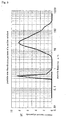
- a commercially-available zeolite catalyst is formulated to have a slurry concentration of 2% by weight and this is subjected to anhydrous organic reaction for 30 hours.
- Fig. 4 and Fig. 5 show a particle size distribution pattern of the zeolite catalyst before and after the reaction.
- Trough the reaction about 10 % of the aggregated zeolite particles were ground and broken owing to the stirring in the reactor and to the collision of the zeolite catalyst particles to each other.
- the present invention may apply even to separation and recovery of zeolite catalysts of the type that are ground and broken and are could therefore poorly sediment in anhydrous organic reaction liquids.
- water may be directly supplied to the reactor after the reaction.
- water is added to a branch line which is connected to the reactor and to which the anhydrous organic reaction liquid is led from the reactor, and this is stirred with a line mixer or the like.
- a tank for water addition and mixture may be provided after the reactor.
- the resulting mixture may be directly filtered after stirred and mixed.
- the mixture is filtered via a tank in which the crystal may be fully aggregated therein.
- the amount of water to be added may be from 0.001 to 1.0 time by weight of the zeolite catalyst weight in the anhydrous organic reaction liquid. Preferably, it is at most 0.2 times by weight.
- the amount of water to be added is so controlled that the slurry concentration of the zeolite catalyst could be at most 35 % by weight, in view of the slurry flowability and operability of the aqueous phase into which the zeolite catalyst has moved.
- the uppermost limit of the amount of water to be added is not specifically defined. However, if the slurry concentration of the zeolite catalyst in the aqueous phase is too much lowered in industrial-scale lines, then it is unfavorable since the line scale and the load to waste water treatment may increase.
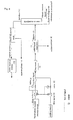
- Fig. 6 is a flowchart of one example of the process of the invention, in which a small amount of water is added to the system so as to aggregate the zeolite catalyst suspended in a anhydrous liquid-phase organic reaction liquid, and then this is subjected to solid-liquid separation.
- the anhydrous organic reaction liquid (1) is taken out from a reactor, and its flow rate is controlled by the flow meter (2) equipped with a sensor and by the flow rate-controlling valve (3), and water is added thereto via the flow meter (4) equipped with a sensor and the valve (5) that act for water flow rate control to a predetermined ratio relative to the anhydrous organic reaction liquid flow rate output data from the sensor thereof in such a controlled manner that a predetermined amount of water could be added to the line.
- this is stirred and mixed by the line mixer (6), and then led to the solid-liquid separator (7).
- a pressure-backwashable, closed-type filter is especially preferred, which has a cylindrical filter structure of a filter cloth or a ceramic filter installed inside it.
- a filter cloth is used for the filter structure for the solid-liquid separator in Fig. 6.
- the filter of the type is as follows: The mixture to be filtered is passed through it, and the zeolite catalyst having stuck to the filter cloth is dried through aeration, and peeled from it in a mode of back-blowing of an inert gas such as pressure nitrogen thereto, and the thus-solidified zeolite catalyst is taken out from the bottom of the filter (8).
- the filter of the type is a FUNDABAC filter (IHI FUNDABAC filter).
- the solid zeolite catalyst thus collected is dried, subjected to solvent removal, and calcinated, and it may be recycled as a regenerated zeolite catalyst.
- water may dissolve in the anhydrous liquid-phase organic reaction liquid to a degree lower than the solubility thereof since water is added to the system in this process.
- the component to be recycled is a light-boiling-point substance relative to the product produced through anhydrous liquid-phase organic reaction
- the component that contains water and is to be recycled is taken out from the distillate (11) from the distillation column (10) where the light-boiling-point substance is separated, and when the distillate condensate could undergo two-phase separation, then a water separator tank is provided in the line and the organic phase (12) separated in the tank may be directly recycled to the reactor.
- water may lower the zeolite catalyst potency
- the water-containing catalyst is passed through the water removal column (13), or it is dried in a drying column provided in the line, and then it may be recycled.
- Water (14) having been removed from the catalyst may be processed for drainage, but is preferably reused for water to be added to the anhydrous liquid-phase organic reaction liquid for separation of the zeolite catalyst from it.
- Fig. 7 is a flowchart of one example of the process of the invention, in which excess water is added to a anhydrous liquid-phase organic reaction liquid until two-phase separation into aqueous phase and organic phase, and the zeolite catalyst having moved to the aqueous phase is separated through liquid-liquid separation from the anhydrous liquid-phase organic reaction liquid along with the aqueous phase from it.
- the process is effective when the slurry concentration of the zeolite catalyst in the anhydrous liquid-phase organic reaction liquid is low and when the scale of the step of separation and recovery of the zeolite catalyst is great.
- the zeolite catalyst can be efficiently concentrated in the aqueous phase according to the process of this type, and the scale of the step of separation and recovery of the zeolite catalyst may be reduced.
- the anhydrous organic reaction liquid (1) is taken out from a reactor, and its flow rate is controlled by the flow meter (2) equipped with a sensor and by the flow rate-controlling valve (3), and water is added thereto via the flow meter (4) and the valve (5) that act for water flow rate control to a predetermined ratio relative to the anhydrous organic reaction liquid flow rate output data from the sensor thereof in such a controlled manner that a predetermined amount of water could be added to the line.
- the liquid separation tank is a liquid-liquid separable tank equipped with a surface level meter or the like.
- the organic phase of the anhydrous organic reaction liquid is processed in the same manner as in the process of Fig. 6.
- the zeolite catalyst-containing aqueous phase is led to a solid-liquid separator like that in Fig. 6, or is led to a decanter in which the grown zeolite particles are recovered.
- the filtrate contains fine particles of the zeolite catalyst, and it is recycled for water to be added to the liquid-phase organic reaction liquid.
- a 100-ml four-neck flask was equipped with a reflux condenser, a thermometer, a chlorine inlet duct, and a sampling duct. This was so designed that waste chlorine gas could be exhausted from the top of the reflux condenser and trapped in an aqueous sodium hydroxide solution. Heating it was effected in an oil bath.
- a 100-ml four-neck flask was equipped with a reflux condenser, a thermometer, a chlorine inlet duct, and a sampling duct. This was so designed that waste chlorine gas could be exhausted from the top of the reflux condenser and trapped in an aqueous sodium hydroxide solution. Heating it was effected in an oil bath.
- a 100-ml four-neck flask was equipped with a reflux condenser, a thermometer, a chlorine inlet duct, and a sampling duct. This was so designed that waste chlorine gas could be exhausted from the top of the reflux condenser and trapped in an aqueous sodium hydroxide solution. Heating it was effected in an oil bath.
- a 100-ml four-neck flask was equipped with a reflux condenser, a thermometer, a chlorine inlet duct, and a sampling duct. This was so designed that waste chlorine gas could be exhausted from the top of the reflux condenser and trapped in an aqueous sodium hydroxide solution. Heating it was effected in an oil bath.
- the chlorine gas flow rate was controlled to be 0.026 mol/hr.
- the water content of the fluorine-containing K-L-type zeolite that had been prepared in Example 2 and calcinated at 400°C for 1 hour was 0.1 % by weight.
- a 100-ml four-neck flask was equipped with a reflux condenser, a thermometer, a chlorine inlet duct. and a sampling duct. This was so designed that waste chlorine gas could be exhausted from the top of the reflux condenser and trapped in an aqueous sodium hydroxide solution. Heating it was effected in an oil bath.
- a 100-ml four-neck flask was equipped with a reflux condenser, a thermometer, a chlorine inlet tube, and a sampling duct. This was so designed that waste chlorine gas could be exhausted from the top of the reflux condenser and trapped in an aqueous sodium hydroxide solution. Heating it was effected in an oil bath.
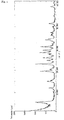
- the resulting product was analyzed through X-ray diffraction, and its pattern is as in Fig. 1. This confirms that the product is an L-type zeolite.
- the X-ray diffraction condition was as follows: The X-ray source was Cu/40 kV/30 mA, and the scanning speed was 3 degrees/min.
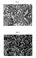
- the product was analyzed for its morphology with a field emission scanning electronic microscope (FE-SEM), and Fig. 2 shows its image. This confirms that almost all the crystallites had a size of at most 100 nm.
- Tosoh's K-L-type zeolite was analyzed for its morphology with a field emission scanning electronic microscope (FE-SEM), and Fig. 3 shows its image. This confirms that almost all the crystals had a size of from 300 nm to 500 nm.
- FE-SEM field emission scanning electronic microscope
- hydrous silicate having an SiO 2 content of 91.6 wt.%, an Al 2 O 3 content of 0.33 wt.%, an NaOH content of 0.27 wt.%, and an H 2 O content of 7.8 wt.%
- Nipsil VN-3 from Nippon Silica
- aluminium hydroxide from Wako Pure Chemicals
- potassium hydroxide having a KOH content of 85.5 wt.% and an H 2 O content of 14.5 wt. %, from Sigma Aldrich Japan
- a mixture of the following composition was prepared. 8K 2 O:Al 2 O 3 :20SiO 2 :400H 2 O (by mol)
- the chlorine gas flow rate was controlled to be 0.08 mol/hr.
- the water content of the L-type zeolite having the crystal size of at most 100 nm that had been prepared in Example 13 and calcinated at 400°C for 1 hour was 0.1% by weight.
- a 100-ml four-neck flask was equipped with a reflux condenser, a thermometer, a chlorine inlet tube, and a sampling duct. This was so designed that waste chlorine gas could be exhausted from the top of the reflux condenser and trapped in an aqueous sodium hydroxide solution. Heating it was effected in an oil bath.
- a 100-ml four-neck flask was equipped with a reflux condenser, a thermometer, a chlorine inlet tube, and a sampling duct. This was so designed that waste chlorine gas could be exhausted from the top of the reflux condenser and trapped in an aqueous sodium hydroxide solution. Heating it was effected in an oil bath.
- a 100-ml four-neck flask was equipped with a reflux condenser, a thermometer, a chlorine inlet tube, and a sampling duct. This was so designed that waste chlorine gas could be exhausted from the top of the reflux condenser and trapped in an aqueous sodium hydroxide solution. Heating it was effected in an oil bath.
- a 100-ml four-neck flask was equipped with a reflux condenser, a thermometer, a chlorine inlet tube, and a sampling duct. This was so designed that waste chlorine gas could be exhausted from the top of the reflux condenser and trapped in an aqueous sodium hydroxide solution. Heating it was effected in an oil bath.
- the chlorine gas flow rate was controlled to be 0.082 mol/hr.
- the water content of the K-L-type zeolite that had been calcinated at 400°C for 1 hour was 0.1% by weight.
- a 100-ml four-neck flask was equipped with a reflux condenser, a thermometer, a chlorine inlet tube, and a sampling duct. This was so designed that waste chlorine gas could be exhausted from the top of the reflux condenser and trapped in an aqueous sodium hydroxide solution. Heating it was effected in an oil bath.
- the chlorine gas flow rate was controlled to be 0.026 mol/hr.
- the water content of the L-type zeolite having the crystal size of at most 100 nm that had been prepared in Example 14 and calcinated at 400°C for 1 hour was 0.1 % by weight.
- a 100-ml four-neck flask was equipped with a reflux condenser, a thermometer, a chlorine inlet tube, and a sampling duct. This was so designed that waste chlorine gas could be exhausted from the top of the reflux condenser and trapped in an aqueous sodium hydroxide solution. Heating it was effected in an oil bath.
- the chlorine gas flow rate was controlled to be 0.026 mol/hr.
- the water content of the fluorine-containing L-type zeolite having the crystal size of at most 100 nm that had been prepared in Example 19 and calcinated at 400°C for 1 hour was 0.1% by weight.
- a 100-ml four-neck flask was equipped with a reflux condenser, a thermometer, a chlorine inlet tube, and a sampling duct. This was so designed that waste chlorine gas could be exhausted from the top of the reflux condenser and trapped in an aqueous sodium hydroxide solution. Heating it was effected in an oil bath.
- the chlorine gas flow rate was controlled to be 0.026 mol/hr.
- the water content of the fluorine-containing L-type zeolite having the crystal size of at most 100 nm that had been prepared in Example 19 and calcinated at 165°C for 12 hours was 1.3% by weight.
- a 100-ml four-neck flask was equipped with a reflux condenser, a thermometer, a chlorine inlet tube, and a sampling duct. This was so designed that waste chlorine gas could be exhausted from the top of the reflux condenser and trapped in an aqueous sodium hydroxide solution. Heating it was effected in an oil bath.
- a 100-ml four-neck flask was equipped with a reflux condenser, a thermometer, a chlorine inlet tube, and a sampling duct. This was so designed that waste chlorine gas could be exhausted from the top of the reflux condenser and trapped in an aqueous sodium hydroxide solution. Heating it was effected in an oil bath.
- a 100-ml four-neck flask was equipped with a reflux condenser, a thermometer, a chlorine inlet tube, and a sampling duct. This was so designed that waste chlorine gas could be exhausted from the top of the reflux condenser and trapped in an aqueous sodium hydroxide solution. Heating it was effected in an oil bath.
- a 100-ml four-neck flask was equipped with a reflux condenser, a thermometer, a chlorine inlet tube, and a sampling duct. This was so designed that waste chlorine gas could be exhausted from the top of the reflux condenser and trapped in an aqueous sodium hydroxide solution. Heating it was effected in an oil bath.
- a 100-ml four-neck flask was equipped with a reflux condenser, a thermometer, a chlorine inlet tube, and a sampling duct. This was so designed that waste chlorine gas could be exhausted from the top of the reflux condenser and trapped in an aqueous sodium hydroxide solution. Heating it was effected in an oil bath.
- a 100-ml four-neck flask was equipped with a reflux condenser, a thermometer, a chlorine inlet tube, and a sampling duct. This was so designed that waste chlorine gas could be exhausted from the top of the reflux condenser and trapped in an aqueous sodium hydroxide solution. Heating it was effected in an oil bath.
- a 100-ml four-neck flask was equipped with a reflux condenser, a thermometer, a chlorine inlet tube, and a sampling duct. This was so designed that waste chlorine gas could be exhausted from the top of the reflux condenser and trapped in an aqueous sodium hydroxide solution. Heating it was effected in an oil bath.
- a 100-ml four-neck flask was equipped with a reflux condenser, a thermometer, a chlorine inlet tube, and a sampling duct. This was so designed that waste chlorine gas could be exhausted from the top of the reflux condenser and trapped in an aqueous sodium hydroxide solution. Heating it was effected in an oil bath.
- a 100-ml four-neck flask was equipped with a reflux condenser, a thermometer, a chlorine inlet tube, and a sampling duct. This was so designed that waste chlorine gas could be exhausted from the top of the reflux condenser and trapped in an aqueous sodium hydroxide solution. Heating it was effected in an oil bath.
- a 100-ml four-neck flask was equipped with a reflux condenser, a thermometer, a chlorine inlet tube, and a sampling duct. This was so designed that waste chlorine gas could be exhausted from the top of the reflux condenser and trapped in an aqueous sodium hydroxide solution. Heating it was effected in an oil bath.
- the tertiary butylbenzene conversion was 80 %, and the production ratio of para-chloro-tert-butylbenzene/(para-chloro-tert-butylbenzene + meta-chloro-tert-butylbenzene + ortho-chloro-tert-butylbenzene) was 201.
- a 100-ml four-neck flask was equipped with a reflux condenser, a thermometer, a chlorine inlet tube, and a sampling duct. This was so designed that waste chlorine gas could be exhausted from the top of the reflux condenser and trapped in an aqueous sodium hydroxide solution. Heating it was effected in an oil bath.
- a 100-ml four-neck flask was equipped with a reflux condenser, a thermometer, a chlorine inlet tube, and a sampling duct. This was so designed that waste chlorine gas could be exhausted from the top of the reflux condenser and trapped in an aqueous sodium hydroxide solution. Heating it was effected in an oil bath.
- the tertiary butylbenzene conversion was 72 %, and the production ratio of para-chloro-tert-butylbenzene/(para-chloro-tert-butylbenzene + meta-chloro-tert-butylbenzene + ortho-chloro-tert-butylbenzene) was 49.
- a 100-ml four-neck flask was equipped with a reflux condenser, a thermometer, a chlorine inlet tube, and a sampling duct. This was so designed that waste chlorine gas could be exhausted from the top of the reflux condenser and trapped in an aqueous sodium hydroxide solution. Heating it was effected in an oil bath.
- a 100-ml four-neck flask was equipped with a reflux condenser, a thermometer, a chlorine inlet tube, and a sampling duct. This was so designed that waste chlorine gas could be exhausted from the top of the reflux condenser and trapped in an aqueous sodium hydroxide solution. Heating it was effected in an oil bath.
- a 100-ml four-neck flask was equipped with a reflux condenser, a thermometer, a chlorine inlet tube, and a sampling duct. This was so designed that waste chlorine gas could be exhausted from the top of the reflux condenser and trapped in an aqueous sodium hydroxide solution. Heating it was effected in an oil bath.
- a 100-ml four-neck flask was equipped with a reflux condenser, a thermometer, a chlorine inlet tube, and a sampling duct. This was so designed that waste chlorine gas could be exhausted from the top of the reflux condenser and trapped in an aqueous sodium hydroxide solution. Heating it was effected in an oil bath.
- a 100-ml four-neck flask was equipped with a reflux condenser, a thermometer, a chlorine inlet tube, and a sampling duct. This was so designed that waste chlorine gas could be exhausted from the top of the reflux condenser and trapped in an aqueous sodium hydroxide solution. Heating it was effected in an oil bath.
- a 100-ml four-neck flask was equipped with a reflux condenser, a thermometer, a chlorine inlet tube, and a sampling duct. This was so designed that waste chlorine gas could be exhausted from the top of the reflux condenser and trapped in an aqueous sodium hydroxide solution. Heating it was effected in an oil bath.
- a 100-ml four-neck flask was equipped with a reflux condenser, a thermometer, a chlorine inlet tube, and a sampling duct. This was so designed that waste chlorine gas could be exhausted from the top of the reflux condenser and trapped in an aqueous sodium hydroxide solution. Heating it was effected in an oil bath.
- a 100-ml four-neck flask was equipped with a reflux condenser, a thermometer, a chlorine inlet tube, and a sampling duct. This was so designed that waste chlorine gas could be exhausted from the top of the reflux condenser and trapped in an aqueous sodium hydroxide solution. Heating it was effected in an oil bath.
- a 100-ml four-neck flask was equipped with a reflux condenser, a thermometer, a chlorine inlet tube, and a sampling duct. This was so designed that waste chlorine gas could be exhausted from the top of the reflux condenser and trapped in an aqueous sodium hydroxide solution. Heating it was effected in an oil bath.
- a 100-ml four-neck flask was equipped with a reflux condenser, a thermometer, a chlorine inlet tube, and a sampling duct. This was so designed that waste chlorine gas could be exhausted from the top of the reflux condenser and trapped in an aqueous sodium hydroxide solution. Heating it was effected in an oil bath.
- a 100-ml four-neck flask was equipped with a reflux condenser, a thermometer, a chlorine inlet tube, and a sampling duct. This was so designed that waste chlorine gas could be exhausted from the top of the reflux condenser and trapped in an aqueous sodium hydroxide solution. Heating it was effected in an oil bath.
- a 100-ml four-neck flask was equipped with a reflux condenser, a thermometer, a chlorine inlet tube, and a sampling duct. This was so designed that waste chlorine gas could be exhausted from the top of the reflux condenser and trapped in an aqueous sodium hydroxide solution. Heating it was effected in an oil bath.
- a 100-ml four-neck flask was equipped with a reflux condenser, a thermometer, a chlorine inlet tube, and a sampling duct. This was so designed that waste chlorine gas could be exhausted from the top of the reflux condenser and trapped in an aqueous sodium hydroxide solution. Heating it was effected in an oil bath.
- a 200-ml four-neck flask was equipped with a reflux condenser, a thermometer, a chlorine inlet tube, and a sampling duct. This was so designed that waste chlorine gas (hydrochloric acid gas) could be exhausted from the top of the reflux condenser and trapped in an aqueous sodium hydroxide solution. Heating it was effected in an oil bath.
- waste chlorine gas hydrochloric acid gas
- orthoxylene orthoxylene (Sigma Aldrich Japan's first class grade chemical) that had been previously dried with Molecular Sieve 4A to have a water content of 20 ppm, 74.8 g of 1, 2-dichloroethane (Sigma Aldrich Japan's first class grade chemical), and 3.43 g of the fluorine-containing K-L-type zeolite (from Tosoh) that had been prepared in Example 1 and calcinated at 400°C for 1 hour and then cooled in a desiccator were put into the flask, and heated at 80°C with nitrogen gas being introduced thereinto through the chlorine gas inlet tube. After this was heated at 80°C, the nitrogen gas was exchanged for chlorine gas and the reaction was started.
- the chlorine gas flow rate was controlled to be about 0.03 mol/hr.
- a 100-ml four-neck flask was equipped with a reflux condenser, a thermometer, a chlorine inlet tube, and a sampling duct. This was so designed that waste chlorine gas could be exhausted from the top of the reflux condenser and trapped in an aqueous sodium hydroxide solution. Heating it was effected in an oil bath.
- a 1000-ml four-neck flask was equipped with a reflux condenser, a thermometer, a chlorine inlet tube, and a sampling duct. This was so designed that waste chlorine gas could be exhausted from the top of the reflux condenser and trapped in an aqueous sodium hydroxide solution. Heating it was effected in an oil bath.
- Tables 1 and 2 confirm that ⁇ -chloro-orthoxylene was reductively decomposed into orthoxylene.
- Example 41 The completely-reacted solution in Example 41 was further heated up to 160°C and stirred still under heat for 6 hours and 40 minutes, but remarkable decomposition of the chloroalkylbenzene derivative to be purified did not almost occur. Since the compound is stable to heat, it is understood from Tables 1 and 2 that, after the compound is decomposed, it may be purified through distillation.
- a 500-ml four-neck flask was equipped with a reflux condenser, a thermometer, a chlorine inlet tube, and a sampling tube. This was so designed that waste chlorine gas could be exhausted from the top of the reflux condenser and trapped in an aqueous sodium hydroxide solution. Heating it was effected in an oil bath.
- the anhydrous liquid-phase organic liquid produced in the above (1) was rapidly stirred in the flask, and a zeolite catalyst was suspended therein. 100 ml of the liquid was taken into a 200-ml Erlenmeyer flask. 2.3 g of water, corresponding to 0.3 times by weight of the zeolite amount in the collected sample liquid, was added to it, and stirred with a stirrer for 2 minutes so as to disperse water in the reaction liquid. Next, this was filtered under suction through a Nutsche filter device equipped with a 400-mesh filter (ASTM standard). The resulting filtrate was transparent, and no zeolite catalyst was found therein.
- Example 45 the anhydrous liquid-phase organic reaction liquid produced in (1) was fully stirred in the flaks so as to suspend the zeolite catalyst therein. Then, 100 ml of the liquid was taken into a 200-ml Erlenmeyer flask. Thus collected, it was directly filtered under suction through a Nutsche filter device equipped with a 400-mesh filter (ASTM standard). The resulting filtrate was cloudy and milky, and this was contaminated with some zeolite catalyst remaining therein.
- the invention ensures para-selectivity in producing di-substituted halobenzene derivatives from benzene or benzene derivatives, and ensures 1,2,4-tri-selective halogenation in producing tri-substituted halobenzene derivatives from them.
Landscapes
- Chemical & Material Sciences (AREA)
- Organic Chemistry (AREA)
- Chemical Kinetics & Catalysis (AREA)
- Engineering & Computer Science (AREA)
- Materials Engineering (AREA)
- General Chemical & Material Sciences (AREA)
- Crystallography & Structural Chemistry (AREA)
- Organic Low-Molecular-Weight Compounds And Preparation Thereof (AREA)
Abstract
In a process of halogenation of benzene or benzene
derivatives, di-substituted halobenzene derivatives having
para-aromatic compounds or tri-substituted halobenzene
derivatives having 1,2,4-substituted aromatic compounds are
selectively produced. In halogenation of benzene or benzene
derivatives, a fluorine-containing zeolite catalyst such as
L-type zeolite, or a zeolite catalyst having the crystal size
of at most 100 nm is used. The reaction is preferably effected
in the presence of a solvent, and the solvent is preferably a
halogenated compound.
Description
The present invention relates to a process for producing
halobenzene derivatives that are useful for various organic
synthetic chemical substances such as typically medicines and
agricultural chemicals and also for polymer materials. More
precisely, the invention provides a process for selectively
producing para-dihalobenzene derivatives and 1,2,4-substituted
trihalobenzene derivatives.
Halobenzene derivatives are industrially important
compounds as starting materials and intermediates for many
compounds. Dihalobenzene derivatives include three isomers,
ortho, meta and para isomers. In particular, para-halobenzene
derivatives are important as starting materials for various
organic compounds. Para-dichlorobenzene, a type of
para-halobenzene derivatives is has an extremely high industrial
value as a starting material for medicines and agricultural
chemicals and, in addition, it can be used as insecticide and
deodorizer by itself. Trihalobenzene derivatives include three
isomers, 1,2,3-trihalobenzene, 1,2,4-trihalobenzene and
1,3,5-trihalobenzene isomers, as classified depending on the
positions of the substituents thereof. In particular,
1,2,4-trihalobenzene derivatives that have the smallest
molecular size are important as starting materials for various
organic compounds. For example, 4-chloro-orthoxylene is
useful as a starting material and an intermediate for many useful
compounds, for example, as a material for polymers.
Halobenzene derivatives are generally produced by
halogenating benzene and/or benzene derivatives with a Lewis
acid catalyst such as ferric chloride or aluminium chloride.
For example, at present, dichlorobenzene is produced through
industrial chlorination that comprises applying a chlorine vapor
to benzene or monochlorobenzene in the presence of a Lewis acid
catalyst such as ferric chloride or aluminium chloride. However,
the ratio of dichlorobenzene isomers produced according to this
method is from 30 to 40% of ortho-isomer, about 5% of meta-isomer
and from 60 to 70 % of para-isomer, and it is difficult to greatly
vary the production ratio of the isomers in the method.
Accordingly, many studies have heretofore been made for
increasing the para-selectivity in the method. One is to use
zeolite as the catalyst. For example, Journal of Catalysis,
Vol. 60, pp. 110-120 (1979) shows that use of ion-exchangedX-type
or Y-type zeolite as the catalyst for liquid-phase bromination
of halobenzenes gives para-isomers at a higher selectivity than
in conventional methods using a Lewis acid as the catalyst.
JP-A-59-163329 discloses use of L-type zeolite in
liquid-phase nucleic halogenation of benzenes to give
para-dihalobenzenes at high selectivity.
JP-A-57-77631 shows examples of vapor-phase halogenation,
saying that chlorination of monochlorobenzene with a catalyst
of zeolite having a pore size of from 5 angstroms to 13 angstroms,
for example, Molecular Sieve 5A, 10X or 13X or HY-type zeolite
gives paradichlorobenzene at a higher selectivity than in
conventional methods.
4-Chloro-orthoxylene is obtained by chlorinating
ortho-xylene in the presence of a Lewis acid, but in the process,
3-chloro-orthoxylene and α-chloroxylene that do not so much
differ from 4-chloro-orthoxylene in point of the boiling point
thereof are produced. For selectively obtaining the useful
4-chloro-orthoxylene, JP-A-3-81234 discloses a method of
producing 4-chloro-orthoxylene by chlorinating orthoxylene
with a catalyst of L-type zeolite, showing that, when a nitro
group-containing compound is added to the reaction system as
an additive, then the production ratio of
4-chloro-orthoxylene/3-chloro-orthoxylene increases. In
addition, this further says that the chlorinating agent, chlorine
may be diluted, in the section of the detailed description of
the invention. However, the concentration of the diluted agent
is not described therein. In Journal of Catalysis, Vol. 150,
pp. 430-433 (1994), Sudgit B. Kumaretal. show that when K-L-type
zeolite dried at 165°C for 12 hours is used as a catalyst and
when 1, 2-dichloroethane is sued as a solvent, then the production
ratio of 4-chloro-orthoxylene/3-chloro-orthoxylene increases.
JP-B-63-34130 discloses a method for producing
2,5-dichlorotoluene by chlorinating ortho-chlorotoluene with
a catalyst of L-type zeolite.
In Journal of Organic Chemistry, Vol. 38, No. 6, pp.
1243-1245 (1973), Belnard Mirror discloses a method of selective
reductive decomposition of α-halogen in processing three
different types of 4-chloro-benzylchloride derivatives with
zinc/concentrated hydrochloric acid/ethanol. However, the
method is problematic in that a large amount of reagents, 323 %
by weight of zinc/1000 % by weight of hydrochloric acid/200 %
by weight of ethanol relative to the starting material must be
used, and the reaction time and the distillation pre-treatment
(extraction, base treatment, drying, filtration) time are long.
Forindustrial-scalemassproduction, themethodcouldnotalways
be allowed in point of the production costs and the productivity.
In addition, there are many known references that disclose
application of a zeolite catalyst as a solid acid catalyst to
liquid-phase organic reaction. However, most of these disclose
only the catalyst potency of zeolite, and studies of isolation
of zeolite catalyst from reaction liquid are not as yet fully
advanced.
A zeolite catalyst is generally a crystalline powder.
In order that the zeolite catalyst could be effective in a
liquid-phase organic reaction system, the catalyst must be
uniformly suspended therein, and, in addition, in the step of
separating and recovering the zeolite catalyst after the reaction,
it is desirable that the catalyst could rapidly sediment in the
reaction liquid and its separability is good. However, when
a zeolite catalyst is, as it is, directly suspended and reacted,
then it is difficult to separate and recover the catalyst after
the reaction. In other words, since the zeolite catalyst poorly
sediments in the reaction liquid, the separation of the catalyst
from the reaction liquid takes a lot of time, and, in addition,
the recovery and handling of the separated catalyst will be
troublesome.
If the separation of the zeolite catalyst is insufficient,
then it causes some problems in the subsequent step of
purification of the reaction product. For example, in
distillation purification, the filler in the distillation column
maybechokedandtheheatermaybescaled; and in crystallization,
the crystals may be contaminated with zeolite powder.
JP-A-2-45431 discloses, as a prior-art technique, a
method filtering a zeolite catalyst through a porous ceramic
filter that may be intermittently backwashed. JP-A-5-68869
discloses a reaction method of using a cross-flow filter for
separation of the particulate solid catalyst from a liquid
reaction product obtained in a catalyst suspension fluidized
bed reactor. In JP-A-2-45431 and 5-68869, however, the filters
are expensive and, in addition, the filter material choked with
a zeolite catalyst could not be regenerated in ordinary baking.
Further, in continuous reaction lines, a zeolite catalyst must
be continuously or intermittently supplied and the used zeolite
catalyst must be continuously or intermittently taken out, and
the taken-out zeolite catalyst is a slurry. Accordingly, an
additional operation is necessary for recovering the zeolite
catalyst and the reaction liquid from the slurry, and it is a
troublesome operation.
Further, in the cross-flow system in JP-A-5-68869, the
flow rate of the processing solution per the cross area of the
filter line, or that is, the cross-flow linear speed thereof
must be increased for preventing the scaling inside the filter,
and the circulation amount through the filter and the reactor
shall increase in order to maintain the cross-flow linear speed.
When a slurry of zeolite that comprises silica and alumina as
the basic structure thereof is passed through the reaction line
at a cross-flow linear speed of at most 20 m/sec, then the filter
material, the pipe line and the pump may be much worn away and,
in addition, the zeolite catalyst may be further ground to give
an increased amount of fine particles having a size of 1 µm or
less, and the increased amount of such fine particles could not
be ignored. For preventing such fine particles from flowing
out through filters to clog them, the filters must have a further
smaller pore size and they will be therefore more expensive.
JP-A-63-166434 discloses a method for producing p-DCB
(para-dichlorobenzene), which comprises using a shaped zeolite
catalyst and in which the separability of the zeolite catalyst
from the reaction liquid is improved. However, in the method
of JP-A-63-166434, the degree of chlorination is from 98 to 99 %
and is low, and much unreacted chloride remains. In addition,
the zeolite could not be completely prevented from being broken,
though its strength is increased in some degree, and the problems
mentioned hereinabove could not be solved as yet.
JP-A-8-40947 discloses a method of separating a zeolite
catalyst from the liquid reaction product obtained in a zeolite
suspension fluidized bed reactor, in a mode of sedimentation
separation of the catalyst.
In such conventional methods, however, the
para-selectivity in dihalobenzene derivatives, and the
1,2,4-tri-selectivity in trihalobenzene derivatives are as yet
insufficient. In addition, in haloalkylbenzene derivatives,
a very small quantity of impurities such as α-chloroalkylbenzene
derivatives (benzylchloride derivatives) are inevitable as side
products. In addition, separation and recovery of catalysts
from organic reaction liquids, and recycling of catalysts are
unsatisfactory.
Accordingly, in industrial production of dihalobenzene
derivatives, it is extremely important to selectively produce
para-halobenzene derivatives while the other side products,
ortho-halobenzene derivatives and meta-halobenzene derivatives
are reduced as much as possible. In producing trihalobenzene
derivatives, further increase in the 1,2,4-tri-selectivity is
desired. For example, in producing chloro-orthoxylene, when
the production of 3-chloro-orthoxylene that does not so much
differ from it in point of the boiling point thereof could be
reduced and when 4-chloro-orthoxylene of high activity could
be produced more selectively at a higher yield, then the
purification step in the production process could be simplified
and the fixed cost forpurification couldbe reduced. In addition,
if α-chloro-orthoxylene, which may be in chloro-orthoxylene as
an impurity and which could not be readily removed even after
distillation owing to the small boiling point difference
therebetween, could be rapidly and selectively decomposed
without use of a large amount of a catalyst or the like so that
high-purity 4-chloro-orthoxylene couldbe efficiently obtained
through distillation with no specific treatment thereof, then
the load to the step of distillation pretreatment and
purification could be reduced and simplified, and the fixed cost
of the purification step could be reduced, and the producibility
is therefore increased.
In addition, when the catalyst could be recycled, then
the proportional cost may be thereby reduced. In the references
of conventional methods, the reaction selectivity and the
activity of catalysts are disclosed, but nothing is disclosed
relating to recycling of zeolite catalysts that are the most
expensive of all the materials. Repeatedly recycling catalysts,
if possible, may result in reduction in industrial wastes and
reduction in production costs.
We, the present inventors have assiduously studied for
the purpose of solving the problems as above, and, as a result,
have found that, when a zeolite catalyst, which either contains
fluorine or has the crystal size of at most 100 nm is used in
halogenating benzene or benzene derivatives, then
para-substituted halobenzene derivatives or 1,2,4-substituted
halobenzene derivatives can be produced at high selectivity and
high yield, and have reached the present invention.
To solve the above-mentioned problems, the invention
essentially has the following constitution. Specifically, the
invention is a process for halogenation of benzene or benzene
derivatives, which comprises using a fluorine-containing
zeolite catalyst or a zeolite catalyst having the crystal size
of at most 100 nm in halogenation of benzene or benzene
derivatives.
The invention is described in detail hereinunder. The
process for producing halobenzene derivatives of the invention
is characterized in that a zeolite catalyst which either contains
fluorine or has the crystal size of at most 100 nm is used in
halogenation of benzene or benzene derivatives.
In the process of the invention, a fluorine-containing
zeolite catalyst is used. Zeolite as referred to herein is a
crystalline microporous material that has a molecular-size,
uniform pore diameter, and it includes crystalline
aluminosilicate, crystalline metallosilicate, crystalline
metalloaluminosilicate, crystalline aluminophosphate,
crystalline metalloaluminophosphate, crystalline
silicoaluminophosphate. Metallosilicate and
metalloaluminosilicate as referred to herein are those derived
from aluminosilicate by substituting a part or all of aluminium
in aluminosilicate with any other metal than aluminium, such
as gallium, iron, titanium, boron, cobalt or chromium.
Similarly, metalloaluminophosphate is derived from
aluminophosphate by substituting a part of aluminium or
phosphorus therein with any other metal.
Zeolite as referred to herein is meant to include all
zeolite structures described in Atlas of Zeolite Structure Types
(W. M. Meier, D. H. Olson, Ch. Baerlocher, Zeolites), 17(1/2),
1996). Any other new-type zeolites not described in this
reference are also within the scope of the zeolite for use in
the invention. However, preferred for use in the invention are
L-type zeolite, faujasite-type zeolite, A-type zeolite,
MFI-type zeolite, mordenite-type zeolite, β-type zeolite,
Ω-type zeolite, AFI-type zeolite, AEL-type zeolite and ATO-type
zeolite that are easily available. More preferred is a zeolite
having an alkali metal as the cation thereof. The reason is
because the alkali metal in such zeolite could be an active point
for chlorine activation. Even more preferred is an L-type
zeolite for the reasons that para-dihalobenzenes can be produced
at high selectivity, the production ratio of
4-chloro-orthoxylene/3-chloro-orthoxylene increases and the
yield of chloro-orthoxylene is high. At present, the reason
why the use of L-type zeolite may increase the selectivity is
not as yet clarified.
L-type zeolite generally contains K ion as the cation,
but it may contain any others than it.
The fluorine-containing zeolite is described. The
zeolite contains fluorine, and it means that, when the zeolite
is analyzed in a mode of instrumental analysis with an analyzer
capable of detecting fluorine and when fluorine is detected in
the analyzed zeolite, then the zeolite contains fluorine. The
instrumental analysis for fluorine detection includes, for
example, atomic absorption analysis, X-ray photoelectric
spectrophotometry, X-ray microanalysis, ICP (inductive
coupling plasma) analysis, fluorescent X-ray analysis. These
methods for analysis are not specifically defined so far as they
enable fluorine detection. Preferably, however, it is
desirable that at least 0.05 % by weight of fluorine can be detected
in absolute-dry fluorine-containing zeolite. The absolute-dry
zeolite is prepared by calcinating zeolite at 500°C for 2 hours
and then cooling it in a desiccator filled with diphosphorus
pentoxide.
The fluorine-containing zeolite may be obtained by
contacting a fluorine-containing compound with zeolite and then
calcinating it. The mode of contacting the two is not
specifically defined, and it may be effected in a solid phase,
in a liquid phase or in a gas phase. Most preferably, a
fluorine-containing salt is formed into an aqueous solution
thereof, and it is contacted with zeolite. This is preferable
since the aqueous solution can be uniformly contacted with
zeolite. After thus contacted, the zeolite may be directly dried
as it is, or after it is once filtered and then dried without
being washed with water. In order that fluorine is finally fixed
on zeolite, the temperature in calcinating is not specifically
defined. For example, the calcinating may be effected at 300
to 500°C. The fluorine-containing salt is not specifically
defined. Its preferred examples are alkali metal salts such
as potassium fluoride and sodium fluoride, as well as ammonium
fluoride.
Apart from the above, also employable herein is a method
of contacting fluorine gas or hydrogen fluoride gas with zeolite.
When the fluorine-containing zeolite catalyst is used,
then the selectivity of para-halobenzene derivatives or
1,2,4-substituted halobenzene derivatives increases. At
present, however, the reason is not as yet clarified.
Though not specifically defined, the amount of the
fluorine-containing zeolite to be used in halogenation may be
generally from 0.5 to 60 g per mol of the substrate. In
halogenation, when the amount of the zeolite catalyst to be used
is smaller, then it is more desirable from the viewpoint of the
production costs.
It is important that the zeolite for use in the invention
has the crystal size of at most 100 nm. The shape of the crystal
is not specifically defined. The size of the crystal may be
determined through observation with a scanning electronic
microscope. Zeolite is sampled at random, and when the samples
are observed with a scanning electronic microscope, then it is
desirable that at least 50 % of the crystallites in each sample
have a size of at most 100 nm. For accurately judging the crystal
size, it is desirable that the samples are observed at amicroscope
of 20,000 or more magnifications.
Various methods for producing zeolite have heretofore
been disclosed. For example, various production methods are
described in Handbook of Molecular Sieves, R. Szostak, VAN
NOSTRAND RAINHOLD, 1992. In particular, the size of zeolite
crystallites varies depending on the reaction mixture
composition, the crystallization temperature, the
crystallization time and the stirring speed in their production.
Therefore, though not indiscriminately defined, the composition
ratio in the reaction mixture must be most suitably determined
since the size of the crystallite complicatedly varies depending
on the concentration of silica and alumina and on the
concentration of alkali. Regarding the crystallization
condition, when the crystallization temperature is lowered or
the crystallization time is shortened, or when the stirring speed
is increased, then the size of the crystallites may be reduced.
When an organic basic nitrogen compound or a surfactant is in
the reaction mixture, then the size of the crystallites may also
be reduced.
When the zeolite catalyst having the crystal size of at
most 100 nm is used, then the selectivity of para-halobenzene
derivatives or 1,2,4-substituted halobenzene derivatives
increases. At present, the reason is not as yet clarified.
The amount of the zeolite having the crystal size of at
most 100 nm to be used in halogenation is not specificallydefined.
In general, it may be from 0.5 to 60 g per mol of the substrate.
In halogenation, when the amount of the zeolite catalyst to be
used is smaller, then it is more desirable from the viewpoint
of the production costs.
In the process of the invention, benzene or benzene
derivatives are used as the substrate. The benzene derivatives
are meant to indicate compounds that are derived from benzene
by substituting the hydrogen atom thereof with a substituent
such as halogen or alkyl group, for example, halobenzenes and
alkylbenzenes. For example, they are preferably
monohalobenzenes, dihalobenzenes, monoalkylbenzenes, or
dialkylbenzenes. Especially preferred are chlorobenzene,
toluene, orthoxylene. Benzene and benzene derivatives for use
herein are not specifically defined in point of their purity,
and any ones that are industrially available are usable herein.
Their purity is preferably higher, but in general, they contain
some impurities and those containing such impurities are
applicable to the invention.
Preferably, the water content of the substrate, benzene
or benzene derivatives is at most 100 ppm. In the process of
the invention, zeolite is used as the catalyst. Zeolite is
generally hydrophilic and has the property of extremely
selectively absorbing water. Accordingly, when the water
content of the substrate is larger than 100 ppm, then the zeolite
pores may adsorb water and high selectivity could not be attained.
In addition, when water is contained in zeolite, then hydrogen
chloride generated in chlorination may dissolve in water adsorbed
by the zeolite and it gives hydrochloric acid. As a result,
the zeolite structure undergoes aluminium removal, and the
catalyst life is thereby shortened. This is undesirable in the
invention.
The method of reducing the water content of the substrate
is not specifically defined. For example, water-removing
molecular sieve may be added to the substrate to remove water;
or the substrate may be heated to remove water through evaporation.
After water has been thus removed from the substrate, it is
important that the substrate is not exposed to
moisture-containing air.
The process of the invention is halogenation. The
halogenating agent is not specifically defined, and any one may
be used herein. For example, it includes fluorine gas, chlorine
gas, bromine, iodine, sulfuryl chloride. In chlorination, for
example, chlorine gas is most preferred, since it is inexpensive
and is easy to handle and since its application is easy to control
and its reaction pressure is also easy to control.
In halogenation of the process of the invention, the
reaction temperature may be any desired one. However, if the
reaction temperature is too high, then side reaction may increase.
Therefore, the temperature preferably falls between -50°C and
150°C, more preferably between 0°C and 100°C. Specifically, when
the substrate is contacted with a halogenating agent, then the
halogenation is attained. In chlorination, for example,
chlorine gas is applied to benzene or benzene derivatives.
Preferably, the gas is applied to the substrate with stirring.
For more efficient utilization of chlorine, it is desirable that
chlorine gas is applied to a satisfactory depth of the substrate.
The reaction may be effected under increased pressure,
atomospheric pressure reduced pressure. For reducing the
equipment costs, the reaction is preferably effected under
atmospheric pressure.
The reactors for use in the process of the invention may
be any of continuous, batch-type or semibatch-type ones.
Preferably, a solvent is added to the halogenation in
the invention. For example, in producing 4-chloro-orthoxylene,
it is known that, in a conventional method, when a solvent of
dichloroethane and a catalyst of K-L-type zeolite are used, then
the production ratio of
4-chloro-orthoxylene/3-chloro-orthoxylene increases. We,
the present inventors have further tried a fluorine-containing
zeolite catalyst or a zeolite catalyst having the crystal size
of at most 100 nm, and have found that the selectivity increases
beyond expectation, and have reached the present invention. The
reason is not as yet clarified.
It is desirable that the solvent used is recovered through
distillation and recycled from the viewpoint of the production
costs. Accordingly, the solvent for use in the invention
preferably has a satisfactory boiling point difference from the
product and has a low boiling point. The type of the solvent
is not specifically defined. Known halogenated compounds and
nitro-containing compounds are preferably used. Halogenated
compounds are more desirable than nitro-containing compounds
because of higher activity. The halogenated compounds may be
aromatic or aliphatic ones. For example, chlorine compounds
include chlorobenzene, o-, m-, p-dichlorobenzene, chloroform,
carbon tetrachloride, chloroethane, dichloroethane,
trichloroethane, chloropropane, dichloropropane. From the
viewpoint of the later steps and the recyclability, the compounds
having a boiling point of not higher than 160°C are preferred.
In particular, dichloroethanes such as 1,2-dichloroethane, and
dichloropropanes such as 1,2-dichloropropane and
1,3-dichloropropane are preferred since both the activity and
the selectivity are high.
Also preferably, a previously-diluted halogen gas is used
in halogenation in the process of the invention. The type of
the diluting gas is not specifically defined. In view of the
cost and the handlability, inert gas such as nitrogen is most
preferred. For example, when such a previously-diluted
chlorine gas is used for chlorination, then the selectivity of
1,2,4-tri-substituted products increases in the production of
tri-substituted chlorinated derivatives through chlorination
of di-substituted benzene derivatives having a substituent at
an ortho- or meta-position. For example, in chlorination of
orthoxylene, the production ratio of
4-chloro-orthoxylene/3-chloro-orthoxylene increases. In
addition, since the production of the side product, polychloro
compounds is retarded, the yield of chloro-orthoxylene is further
increased. Though the reason is not as yet clarified at present,
it may be presumed that, when a diluting gas is mixed with chlorine
gas and applied to the substrate, then the side product,
hydrochloric acid and others may be removed away from the reaction
system owing to the aeration effect of the mixed gas and, as
a result, the catalyst surface could be cleaned.
The concentration of the previously-diluted halogen gas
is not specifically defined so far at it is lower than 100 mol%.
For example, it may be from 5 mol% to 99 mol%, preferably from
5 mol% to 80 mol%, more preferably from 5 mol% to 50 mol%. For
example, when the concentration of the chlorine gas is lower
than 5 mol% , then the chlorination reaction rate will be extremely
lowered and the reaction time will be prolonged. This is rather
disadvantageous and unfavorable from the economical viewpoint.
Preferably, L-type zeolite having a water content of at
most 1.0% by weight is used for the catalyst.
L-type zeolite is hydrophilic, and when exposed to air,
then it adsorbs moisture in air and generally may have a water
content of from 7 to 10 %. Journal of Catalysis, Vol. 150, pp.
430-433 (1994) discloses a method of activation of catalyst at
165°C for 12 hours. However, even when zeolite is dried according
to the method, about 1.4 % by weight of water still remains in
the processed zeolite. We, the present inventors have realized
the use of an L-type zeolite having a water content of at most
1.0% by weight for the reaction catalyst, according to the method
mentioned below, and have found that the L-type zeolite having
such a low water content exhibits an extremely high selectivity
in a process of producing 4-chloro-orthoxylene, for example,
through chlorination of orthoxylene.
A method of measuring the water content of L-type zeolite
is described below. The weight of zeolite is measured in such
a manner that it is not exposed to air as much as possible, and
this is W1. The zeolite is put into an electric furnace at 500°C
and calcinated therein for 3 hours, and while still hot, this
is put into a desiccator filled with diphosphorus pentoxide and
cooled therein. After this is cooled to room temperature, its
weight is measured in such a manner that it is not exposed to
air as much as possible, and this is W2. The water content of
the zeolite is 100 × (W1 - W2)/W1 (%).
In the process of producing halobenzene derivatives of
the invention, which comprises halogenating benzene derivatives,
it is important that after the benzene derivative has been 100%
converted, it is further halogenated. Heretofore, it has been
said that, if the conversion of benzene derivatives is too high,
then halobenzene derivatives are further halogenated into
dihalobenzene derivatives and this is unfavorable since the unit
requirement of benzene derivatives is lowered. However, we,
the present inventors have found that, when a benzene derivative
has been 100% converted and it is further halogenated, then
the selectivity of para-substituted halobenzene derivatives or
1,2,4-substituted halobenzene derivatives is greatly increased
relative to ortho-substituted halobenzene derivatives or
1,2,3-substituted halobenzene derivatives or α-halobenzenes,
since ortho-substituted halobenzene derivatives or
1,2,3-substituted halobenzene derivatives are more readily
dichlorinated to give high-boiling-point compounds than
para-substituted halobenzene derivatives or 1,2,4-substituted
halobenzene derivatives. The unit requirement of benzene
derivatives may surely lower, but the production of
ortho-substituted halobenzene derivatives or 1,2,3-substituted
halobenzene derivatives as well as α-halobenzenes that are
difficult to separate is reduced and the load to the complicated
purification step after the reaction may be reduced. Concretely,
the product could be easily purified to a high degree even in
a distillation column having a reduced number of stages, and
therefore the yield in the purification step increases. As a
whole, therefore, halobenzene derivatives can be produced at
high yield and at low costs. Further halogenation after 100 %
conversion of benzene derivatives may be attained by prolonging
the reaction time for halogenation.
In particular, in a process of obtaining
4-chloro-orthoxylene by chlorinating orthoxylene, it is
important that orthoxylene is converted to a degree of 95% or
more. Heretofore, it has been said that, if the conversion of
orthoxylene is too high, then 4-chloro-orthoxylene is further
chlorinated into dichloro-orthoxylene and this is unfavorable
since the unit requirement of orthoxylene is lowered. However,
we, the present inventors have found that, when the conversion
of orthoxylene is over 95%, then the selectivity of
4-chloro-orthoxylene is greatly increased relative to
3-chloro-orthoxylene and α-chloro-orthoxylene, since
3-chloro-orthoxylene and α-chloro-orthoxylene are more readily
dichlorinated to give high-boiling-point compounds than
4-chloro-orthoxylene. The unit requirement of orthoxylene may
surely lower, but the production of 3-chloro-orthoxylene and
α-chloro-orthoxylene that are difficult to separate is reduced
and the load to the complicated purification step after the
reaction may be reduced. Concretely, the product could be easily
purified to a high degree even in a distillation column having
a reduced number of stages, and therefore the yield in the
purification step increases. As a whole, therefore,
4-chloro-orthoxylene can be produced at high yield and at low
costs. For increasing the conversion of orthoxylene to 95 %
or more, the reaction time is prolonged until the conversion
reaches at least 95 %. The conversion of 100 % or more is more
preferable since the selectivity is further increased.
In the process of the invention, it is desirable that
from 0.001 to 10 % by weight of a metal and/or a metal salt is
added to a mixture that comprises a haloalkylbenzene derivative
(I) of the following general formula (I) and contains at least
one impurity of an α-haloalkylbenzene derivative (II) of the
following general formula (II) so as to selectively decompose
the α-haloalkylbenzene derivative (II), and the mixture is
preferably purified through distillation into a high-purity
nucleus-halogenated alkylbenzene derivative.
 (In formula (I), the substituents R1 to R6 are independent of
each other; R1 represents a hydrogen atom, or an alkyl group
having from 1 to 4 carbon atoms; R2 to R6 each represent a hydrogen
atom, a halogen atom, or an alkyl group having from 1 to 5 carbon
atoms, and at least one or more of these substituents are any
of a chlorine atom and an alkyl group having from 1 to 5 carbon
atoms. In formula (II), the
substituents R1 to R6 are independent of each other; R1 represents
a hydrogen atom, or an alkyl group having from 1 to 4 carbon
atoms; R2 to R6 each represent a hydrogen atom, a halogen atom,
an alkyl group having from 1 to 5 carbon atoms, or an α-haloalkyl
group having from 1 to 5 carbon atoms, and at least one or more
of these substituents are any of a chlorine atom and a hydrogen
atom.)
(In formula (I), the substituents R1 to R6 are independent of
each other; R1 represents a hydrogen atom, or an alkyl group
having from 1 to 4 carbon atoms; R2 to R6 each represent a hydrogen
atom, a halogen atom, or an alkyl group having from 1 to 5 carbon
atoms, and at least one or more of these substituents are any
of a chlorine atom and an alkyl group having from 1 to 5 carbon
atoms. In formula (II), the
substituents R1 to R6 are independent of each other; R1 represents
a hydrogen atom, or an alkyl group having from 1 to 4 carbon
atoms; R2 to R6 each represent a hydrogen atom, a halogen atom,
an alkyl group having from 1 to 5 carbon atoms, or an α-haloalkyl
group having from 1 to 5 carbon atoms, and at least one or more
of these substituents are any of a chlorine atom and a hydrogen
atom.)
Compounds of formulae (I) and (II) are described. In
formula (I), the groups R1 to R6 are independent of each other,
and when R1 is a hydrogen atom, R2 to R6 each are a hydrogen atom,
a chlorine atom or a methyl group, and one of these groups is
a chlorine atom or a methyl group; and in formula (II), the
substituents R1 to R6 are independent of each other, and when
R1 is a hydrogen atom, R2 to R6 each are a hydrogen atom, a chlorine
atom, a methyl group or an α-chloromethyl group, and at least
one of these group is a chlorine atom, a hydrogen atom or a methyl
group, then the invention produces good results.
The impurities in the mixture include one or more types
of α-haloalkylbenzene derivatives (II), regio-isomers of
haloalkylbenzene derivatives, compound groups produced through
excess chlorination of the desired haloalkylbenzene derivatives,
and residual solvents, but the impurities are not limited to
these.
It is believed that the selective decomposition of
α-haloalkylbenzene derivatives in the invention may include
Friedel-Crafts type alkylation. The minor amount of metal for
selective decomposition of α-haloalkylbenzene derivatives may
be at least one selected from iron, aluminium, antimony, gallium,
zirconium, tin, boron and their salts. The salts are preferably
FeCl3, AlCl3, AlBr3, SbCl5, GaCl3, ZrCl4, BCl3, and BF3. More
preferred are FeCl3, AlCl3, and Fe in view of the rapid reaction
rate and the cost of the metals. Needless-to-say, these are
not limitative. The amount of the metal to be added to the system
is at most 10 % by weight of the mixture comprising, as the
essential ingredient thereof, haloalkylbenzene derivatives
that are to be purified, and the selective decomposition may
be finished within a few minutes. In view of the producibility
and the production costs, the metal amount is preferably from
0.001 to 10% by weight, more preferably from 0.01 to 5 % by
weight.
Regarding its temperature, the decomposition may be
attained at any reaction temperature not lower than room
temperature. However, if the reaction temperature is low, then
the reaction rate will be low. Preferably, the reaction
temperature falls between room temperature and 200°C, more
preferably between 60°C and 200°C. The reaction may go on in
the absence of a solvent, but when the content of the impurity,
α-haloalkylbenzene is over 5 %, the yield may reduce. In such
a case, therefore, it is desirable that an aromatic solvent such
asbenzene, toluene orxylene is added to the system in an equimolar
amount thereof relative to α-haloalkylbenzene. If desired, for
example, dichloropropane, ethylene dichloride, methylene
chloride, chloroform, hydrochloric acid/ethanol, or
hydrochloric acid/methanol solvent may also be used. Except
the case where hydrochloric acid/ethanol or hydrochloric
acid/methanol is used as the solvent, the water content of the
mixture to be decomposed is preferably as small as possible.
More preferably, it is at most 1000 ppm, even more preferably
at most 100 ppm. However, even when the water content is larger
than it, the intended decomposition may be attained so far as
excess metal and/ormetal salt is added to the system. Therefore,
the water content of the mixture is not specifically defined.
The decomposition reaction time may be within 10 minutes so far
as the decomposition temperature, and the type and the amount
of the metal used are suitably determined. After the
decomposition, any additional treatment for metal removal is
unnecessary, and the distillation purification may be finished
with no additional treatment thereto.
The decomposition reaction may be effected under
increased pressure, atmospheric pressure or reduced pressure,
but is preferably effected under atmospheric pressure from the
viewpoint of reducing the equipment costs.
The decomposition reactor for use in the process of the
invention may be any of continuous, batch-type or semibatch-type
ones.
After the reaction according to the process of the
invention, zeolite is separated from the zeolite-containing,
anhydrous liquid-phase organic reaction liquid. For the
separation, it is desirable that water is added to the anhydrous
liquid-phase organic reaction liquid to aggregate the dispersed
zeolite and then this is introduced into a solid-liquid separator
to separate the zeolite catalyst therein.
In the method of separating the zeolite catalyst in the
invention, we, the present inventor do not intend at all to define
a preferred range of the mean particle size of the zeolite.
In this connection, even when an unused zeolite catalyst
has a sufficiently large particle size and, after used, it could
be readily separated and recovered in any known separation method
of sedimentation separation, the zeolite catalyst may be ground
and broken during reaction while stirred in a reactor or depending
on the reaction condition such as the slurry concentration. For
example, a commercially-available zeolite catalyst is
formulated to have a slurry concentration of 2% by weight and
this is subjected to anhydrous organic reaction for 30 hours.
Fig. 4 and Fig. 5 show a particle size distribution pattern of the
zeolite catalyst before and after the reaction. Trough the reaction,
about 10 % of the aggregated zeolite particles were ground and
broken owing to the stirring in the reactor and to the collision
of the zeolite catalyst particles to each other. The present
invention may apply even to separation and recovery of zeolite
catalysts of the type that are ground and broken and are could
therefore poorly sediment in anhydrous organic reaction liquids.
The content of the zeolite catalyst in the anhydrous
organic reaction liquid to be processed is not specifically
defined. Preferably, it is at most 35% by weight of the overall
amount of the anhydrous organic reaction liquid. In general,
when the content of the zeolite catalyst is over 35 % by weight,
then the slurry flowability is lowered and the operability is
therefore lowered.
Regarding the addition of water to the reaction system,
water may be directly supplied to the reactor after the reaction.
Preferably, however, water is added to a branch line which is
connected to the reactor and to which the anhydrous organic
reaction liquid is led from the reactor, and this is stirred
with a line mixer or the like. More preferably, a tank for water
addition and mixture may be provided after the reactor.
When a small amount of water (from 0.001 to 1.0 time by
weight of the zeolite catalyst weight in the anhydrous
liquid-phase organic reaction liquid) is added so as to aggregate
the zeolite catalyst in the anhydrous liquid-phase organic
reaction liquid, the resulting mixture may be directly filtered
after stirred and mixed. Preferably, however, the mixture is
filtered via a tank in which the crystal may be fully aggregated
therein. The amount of water to be added may be from 0.001 to
1.0 time by weight of the zeolite catalyst weight in the anhydrous
organic reaction liquid. Preferably, it is at most 0.2 times
by weight. Though depending on the solubility in water of the
anhydrous liquid-phase organic reaction liquid, when water is
added in an amount of from 1.0 to 1.5 times by weight of the
zeolite catalyst, then the aggregated particles of the zeolite
catalyst may be clayish and may stick to the walls of the reactor
and, as a result, their flowability and operability will be poor.
So far as the amount of water added is adequate, then the zeolite
catalyst may form good aggregated particles and its operability
for separation is good.
On the other hand, when water is added until the system
is separated into an organic phase and an aqueous phase (the
amount of water added is from 1.8 to 100 times by weight of the
zeolite catalyst weight in the anhydrous liquid-phase organic
reaction liquid) , then the mixture is, after stirred and mixed,
led into a tank for liquid-liquid separation equipped with a
surface level meter or the like, and the zeolite catalyst having
moved to the aqueous phase is separated from the anhydrous
liquid-phase organic reaction liquid alongwith the aqueous phase
from it. Preferably, the amount of water to be added is so
controlled that the slurry concentration of the zeolite catalyst
could be at most 35 % by weight, in view of the slurry flowability
and operability of the aqueous phase into which the zeolite
catalyst has moved.
The slurry concentration is defined by the following
formula:
Slurry Concentration (wt.%) of Aqueous Phase
= [(zeolite catalyst weight in anhydrous liquid-phase organic
reaction liquid)/(zeolite catalyst weight in anhydrous
liquid-phase organic reaction liquid + added water weight)]
× 100.
For example, when the slurry concentration of the zeolite
catalyst in a anhydrous liquid-phase organic reaction liquid
is 1 % by weight, then water is added in an amount of 1.86 times
by weight of the zeolite catalyst weight in order that the slurry
concentration of the aqueous phase into which the zeolite
catalyst has moved could be at most 35 %. More preferably, the
amount of water to be added is from 2 to 5 times by weight of
the zeolite catalyst weight.
The uppermost limit of the amount of water to be added
is not specifically defined. However, if the slurry
concentration of the zeolite catalyst in the aqueous phase is
too much lowered in industrial-scale lines, then it is
unfavorable since the line scale and the load to waste water
treatment may increase.
The invention is described with reference to the drawings.
Fig. 6 is a flowchart of one example of the process of
the invention, in which a small amount of water is added to the
system so as to aggregate the zeolite catalyst suspended in a
anhydrous liquid-phase organic reaction liquid, and then this
is subjected to solid-liquid separation. The anhydrous organic
reaction liquid (1) is taken out from a reactor, and its flow
rate is controlled by the flow meter (2) equipped with a sensor
and by the flow rate-controlling valve (3), and water is added
thereto via the flow meter (4) equipped with a sensor and the
valve (5) that act for water flow rate control to a predetermined
ratio relative to the anhydrous organic reaction liquid flow
rate output data from the sensor thereof in such a controlled
manner that a predetermined amount of water could be added to
the line. After the addition, this is stirred and mixed by the
line mixer (6), and then led to the solid-liquid separator (7).
For the solid-liquid separator (7), employable are
filters, centrifuges and thickeners, but filters are preferably
selected. For use in the process, a pressure-backwashable,
closed-type filter is especially preferred, which has a
cylindrical filter structure of a filter cloth or a ceramic filter
installed inside it.
A filter cloth is used for the filter structure for the
solid-liquid separator in Fig. 6. The filter of the type is
as follows: The mixture to be filtered is passed through it,
and the zeolite catalyst having stuck to the filter cloth is
dried through aeration, and peeled from it in a mode of
back-blowing of an inert gas such as pressure nitrogen thereto,
and the thus-solidified zeolite catalyst is taken out from the
bottom of the filter (8). For example, the filter of the type
is a FUNDABAC filter (IHI FUNDABAC filter). The solid zeolite
catalyst thus collected is dried, subjected to solvent removal,
and calcinated, and it may be recycled as a regenerated zeolite
catalyst.
On the other hand, the anhydrous liquid-phase organic
reaction liquid from which the zeolite catalyst has been removed
is taken out of the solid-liquid separator as a filtrate (9),
and this is then led to the next purification step.
When the anhydrous liquid-phase organic reaction liquid
contains a material to be recycled, or that is, when the anhydrous
organic reaction liquid contains a reaction solvent or an
unreacted starting material and when this is recovered and
recycled to the reactor, then water may dissolve in the anhydrous
liquid-phase organic reaction liquid to a degree lower than the
solubility thereof since water is added to the system in this
process. For example, when the component to be recycled is a
light-boiling-point substance relative to the product produced
through anhydrous liquid-phase organic reaction, then the
component that contains water and is to be recycled is taken
out from the distillate (11) from the distillation column (10)
where the light-boiling-point substance is separated, and when
the distillate condensate could undergo two-phase separation,
then a water separator tank is provided in the line and the organic
phase (12) separated in the tank may be directly recycled to
the reactor. When water may lower the zeolite catalyst potency,
then the water-containing catalyst is passed through the water
removal column (13), or it is dried in a drying column provided
in the line, and then it may be recycled.
Water (14) having been removed from the catalyst may be
processed for drainage, but is preferably reused for water to
be added to the anhydrous liquid-phase organic reaction liquid
for separation of the zeolite catalyst from it.
Fig. 7 is a flowchart of one example of the process of
the invention, in which excess water is added to a anhydrous
liquid-phase organic reaction liquid until two-phase separation
into aqueous phase and organic phase, and the zeolite catalyst
having moved to the aqueous phase is separated through
liquid-liquid separation from the anhydrous liquid-phase
organic reaction liquid along with the aqueous phase from it.
The process is effective when the slurry concentration of the
zeolite catalyst in the anhydrous liquid-phase organic reaction
liquid is low and when the scale of the step of separation and
recovery of the zeolite catalyst is great. In such a case, the
zeolite catalyst can be efficiently concentrated in the aqueous
phase according to the process of this type, and the scale of
the step of separation and recovery of the zeolite catalyst may
be reduced.
The anhydrous organic reaction liquid (1) is taken out
from a reactor, and its flow rate is controlled by the flow meter
(2) equipped with a sensor and by the flow rate-controlling valve
(3), and water is added thereto via the flow meter (4) and the
valve (5) that act for water flow rate control to a predetermined
ratio relative to the anhydrous organic reaction liquid flow
rate output data from the sensor thereof in such a controlled
manner that a predetermined amount of water could be added to
the line.
After water is added to the anhydrous organic reaction
liquid, the two are mixed by the line mixer (6) and led to the
liquid separation tank (14). The liquid separation tank is a
liquid-liquid separable tank equipped with a surface level meter
or the like. When the organic phase is light, then the anhydrous
liquid-phase organic reaction liquid is taken out from the top
of the column (15) and the aqueous phase that contains the zeolite
catalyst is taken out from the bottom thereof (16). The organic
phase of the anhydrous organic reaction liquid is processed in
the same manner as in the process of Fig. 6. The zeolite
catalyst-containing aqueous phase is led to a solid-liquid
separator like that in Fig. 6, or is led to a decanter in which
the grown zeolite particles are recovered. The filtrate
contains fine particles of the zeolite catalyst, and it is
recycled for water to be added to the liquid-phase organic
reaction liquid.
The invention is described with reference to the following
Examples.
6.43 g of anhydrous potassium fluoride and 60 ml of
distilled water were added to 10 g (absolute dry) of Tosoh's
K-L-type zeolite, stirred (75°C) for 5 hours, and filtered, and
the resulting cake was dried overnight at 120°C.
3.22 g of anhydrous potassium fluoride and 60 ml of
distilled water were added to 10 g (absolute dry) of Tosoh's
K-L-type zeolite, stirred (room temperature) for 10 minutes,
and filtered, and the resulting cake was dried overnight at 120°C.
A 100-ml four-neck flask was equipped with a reflux
condenser, a thermometer, a chlorine inlet duct, and a sampling
duct. This was so designed that waste chlorine gas could be
exhausted from the top of the reflux condenser and trapped in
an aqueous sodium hydroxide solution. Heating it was effected
in an oil bath.
16.96 g of orthoxylene (Sigma Aldrich Japan' s first class
grade chemical) that had been previously dried with Molecular
Sieve 4A to have a water content of 20 ppm, 60 ml of
1,2-dichloroethane (Sigma Aldrich Japan's first class grade
chemical), and 3.39g of the fluorine-containingK-L-type zeolite
(from Tosoh) that had been prepared in Example 1 and calcinated
at 400°C for 1 hour and then cooled in a desiccator were put
into the flask, and heated at 80°C with nitrogen gas being
introduced thereinto through the chlorine gas inlet tube. After
this was heated at 80°C, the nitrogen gas was exchanged for
chlorine gas and the reaction was started. The chlorine gas
flow rate was controlled to be 0.08 mol/hr. The water content
of the fluorine-containing K-L-type zeolite that had been
prepared in Example 1 and calcinated at 400°C for 1 hour was
0.1% by weight.
After 3 hours, the orthoxylene conversion was 64%, and
the production ratio of
4-chloro-orthoxylene/3-chloro-orthoxylene was 9.8.
A 100-ml four-neck flask was equipped with a reflux
condenser, a thermometer, a chlorine inlet duct, and a sampling
duct. This was so designed that waste chlorine gas could be
exhausted from the top of the reflux condenser and trapped in
an aqueous sodium hydroxide solution. Heating it was effected
in an oil bath.
16.96 g of orthoxylene (Sigma Aldrich Japan's first class
grade chemical) that had been previously dried with Molecular
Sieve 4A to have a water content of 20 ppm, 60 ml of
1,2-dichloroethane (Sigma Aldrich Japan's first class grade
chemical), and 3.39 g of a K-L-type zeolite (from Tosoh) that
had been calcinated at 400°C for 1 hour and then cooled in a
desiccator were put into the flask, and heated at 80°C with
nitrogen gas being introduced thereinto through the chlorine
gas inlet tube. After this was heated at 80°C, the nitrogen
gas was exchanged for chlorine gas and the reaction was started.
The chlorine gas flow rate was controlled to be 0.08 mol/hr.
The water content of the K-L-type zeolite that had been calcinated
at 400°C for 1 hour was 0.1 % by weight.
After 2 hours, the orthoxylene conversion was 49%, and
the production ratio of
4-chloro-orthoxylene/3-chloro-orthoxylene was 8.1. After 4
hours, the orthoxylene conversion was 94%, and the production
ratio of 4-chloro-orthoxylene/3-chloro-orthoxylene was 8.5.
A 100-ml four-neck flask was equipped with a reflux
condenser, a thermometer, a chlorine inlet duct, and a sampling
duct. This was so designed that waste chlorine gas could be
exhausted from the top of the reflux condenser and trapped in
an aqueous sodium hydroxide solution. Heating it was effected
in an oil bath.
53 g of orthoxylene (Sigma Aldrich Japan's first class
grade chemical) that had been previously dried with Molecular
Sieve 4A to have a water content of 20 ppm, and 2.5 g of the
fluorine-containing K-L-type zeolite (from Tosoh) that had been
prepared in Example 1 and calcinated at 400°C for 1 hour and
then cooled in a desiccator were put into the flask, and heated
at 80°C with nitrogen gas being introduced thereinto through
the chlorine gas inlet tube. After this was heated at 80°C,
the nitrogen gas was exchanged for chlorine gas and the reaction
was started. The chlorine gas flow rate was controlled to be
0.13 mol/hr. The water content of the fluorine-containing
K-L-type zeolite that had been prepared in Example 1 and
calcinated at 400°C for 1 hour was 0.1% by weight.
After 4 hours, the orthoxylene conversion was 42%, and
the production ratio of
4-chloro-orthoxylene/3-chloro-orthoxylene was 1.8.
A 100-ml four-neck flask was equipped with a reflux
condenser, a thermometer, a chlorine inlet duct, and a sampling
duct. This was so designed that waste chlorine gas could be
exhausted from the top of the reflux condenser and trapped in
an aqueous sodium hydroxide solution. Heating it was effected
in an oil bath.
53 g of orthoxylene (Sigma Aldrich Japan's first class
grade chemical) that had been previously dried with Molecular
Sieve 4A to have a water content of 20 ppm, and 2.5 g of a K-L-type
zeolite (from Tosoh) that had been calcinated at 400°C for 1
hour and then cooled in a desiccator were put into the flask,
and heated at 80°C with nitrogen gas being introduced thereinto
through the chlorine gas inlet tube. After this was heated at
80°C, the nitrogen gas was exchanged for chlorine gas and the
reaction was started. The chlorine gas flow rate was controlled
to be 0.13 mol/hr. The water content of the K-L-type zeolite
that had been calcinated at 400°C for 1 hour was 0.1% by weight.
After 4 hours, the orthoxylene conversion was 46 %, and
the production ratio of
4-chloro-orthoxylene/3-chloro-orthoxylene was 1.6.
A 100-ml four-neck flask was equipped with a reflux
condenser, a thermometer, a chlorine inlet duct, and a sampling
duct. This was so designed that waste chlorine gas could be
exhausted from the top of the reflux condenser and trapped in
an aqueous sodium hydroxide solution. Heating it was effected
in an oil bath.
16.96 g of orthoxylene (Sigma Aldrich Japan's first class
grade chemical) that had been previously dried with Molecular
Sieve 4A to have a water content of 20 ppm, 60 ml of
1,2-dichloroethane (Sigma Aldrich Japan's first class grade
chemical), and 0.17 g of the fluorine-containing K-L-type zeolite
(from Tosoh) that had been prepared in Example 2 and calcinated
at 400°C for 1 hour and then cooled in a desiccator were put
into the flask, and heated at 80°C with nitrogen gas being
introduced thereinto through the chlorine gas inlet tube. After
this was heated at 80°C, the nitrogen gas was exchanged for
chlorine gas and the reaction was started. The chlorine gas
flow rate was controlled to be 0.026 mol/hr. The water content
of the fluorine-containing K-L-type zeolite that had been
prepared in Example 2 and calcinated at 400°C for 1 hour was
0.1 % by weight.
After 6 hours, the orthoxylene conversion was 97 %, and
the production ratio of
4-chloro-orthoxylene/3-chloro-orthoxylene was 8.7.
A 100-ml four-neck flask was equipped with a reflux
condenser, a thermometer, a chlorine inlet duct. and a sampling
duct. This was so designed that waste chlorine gas could be
exhausted from the top of the reflux condenser and trapped in
an aqueous sodium hydroxide solution. Heating it was effected
in an oil bath.
16.96 g of orthoxylene (Sigma Aldrich Japan's first class
grade chemical) that had been previously dried with Molecular
Sieve 4A to have a water content of 20 ppm, 60 ml of
1,2-dichloroethane (Sigma Aldrich Japan's first class grade
chemical), and 0.17 g of the fluorine-containing K-L-type zeolite
(from Tosoh) that had been prepared in Example 2 and calcinated
at 400°C for 1 hour and then cooled in a desiccator were put
into the flask, and heated at 80°C with nitrogen gas being
introduced thereinto through the chlorine gas inlet tube. After
this was heated at 80°C, the nitrogen gas was mixed with chlorine
gas and the reaction was started. The gas blend ratio was
nitrogen gas/chlorine gas = 0.05 by volume. The chlorine gas
flow rate was controlled to be 0.026 mol/hr. The water content
of the fluorine-containing K-L-type zeolite that had been
prepared in Example 2 and calcinated at 400°C for 1 hour was
0.1 % by weight.
After 6 hours, the orthoxylene conversion was 98 %, and
the production ratio of
4-chloro-orthoxylene/3-chloro-orthoxylene was 8.8.
The same process as in Example 6 was carried out, in which,
however, the gas blend ratio was nitrogen gas/chlorine gas =
0.25 by volume.
After 6 hours, the orthoxylene conversion was 96%, and
the production ratio of
4-chloro-orthoxylene/3-chloro-orthoxylene was 8.9.
The same process as in Example 6 was carried out, in which,
however, the gas blend ratio was nitrogen gas/chlorine gas =
1 by volume.
After 6 hours, the orthoxylene conversion was 97%, and
the production ratio of
4-chloro-orthoxylene/3-chloro-orthoxylene was 9.2.
The same process as in Example 6 was carried out, in which,
however, the gas blend ratio was nitrogen gas/chlorine gas =
2 by volume.
After 6 hours, the orthoxylene conversion was 97%, and
the production ratio of
4-chloro-orthoxylene/3-chloro-orthoxylene was 9.9.
The same process as in Example 6 was carried out, in which,
however, the gas blend ratio was nitrogen gas/chlorine gas =
4 by volume.
After 6 hours, the orthoxylene conversion was 94%, and
the production ratio of
4-chloro-orthoxylene/3-chloro-orthoxylene was 10.3.
The same process as in Example 6 was carried out, in which,
however, the gas blend ratio was nitrogen gas/chlorine gas =
9 by volume.
After 6 hours, the orthoxylene conversion was 85 %, and
the production ratio of
4-chloro-orthoxylene/3-chloro-orthoxylene was 10.4.
The same process as in Example 6 was carried out, in which,
however, the gas blend ratio was nitrogen gas/chlorine gas =
30 by volume.
After 6 hours, the orthoxylene conversion was 70 %, and
the production ratio of
4-chloro-orthoxylene/3-chloro-orthoxylene was 10.5.
A 100-ml four-neck flask was equipped with a reflux
condenser, a thermometer, a chlorine inlet tube, and a sampling
duct. This was so designed that waste chlorine gas could be
exhausted from the top of the reflux condenser and trapped in
an aqueous sodium hydroxide solution. Heating it was effected
in an oil bath.
16. 96 g of orthoxylene (Sigma Aldrich Japan' s first class
grade chemical) that had been previously dried with Molecular
Sieve 4A to have a water content of 20 ppm, 60 ml of
1,2-dichloroethane (Sigma Aldrich Japan's first class grade
chemical), and 0.17 g of a K-L-type zeolite (from Tosoh) that
had been calcinated at 400°C for 1 hour and then cooled in a
desiccator were put into the flask, and heated at 80°C with
nitrogen gas being introduced thereinto through the chlorine
gas inlet tube. After this was heated at 80°C, the nitrogen
gas was mixed with chlorine gas and the reaction was started.
The gas blend ratio was nitrogen gas/chlorine gas = 4 by volume.
The chlorine gas flow rate was controlled to be 0.026 mol/hr.
The water content of the K-L-type zeolite that had been calcinated
at 400°C for 1 hour was 0.1% by weight.
After 6 hours, the orthoxylene conversion was 91%, and
the production ratio of
4-chloro-orthoxylene/3-chloro-orthoxylene was 7.5.
Using Ludox HS-30 (from DuPont) as a silica source,
aluminium hydroxide (from Wako Pure Chemicals) as an aluminium
source, and potassium hydroxide (having a KOH content of 85.5
wt.% and an H2O content of 14.5 wt.%, from Sigma Aldrich Japan)
as a potassium source, a mixture of the following composition
was prepared.
8K2O:Al2O3:20SiO2:200H2O (by mol)
8K2O:Al2O3:20SiO2:200H2O (by mol)
Concretely, 62. 99 g of potassium hydroxide was dissolved
in 35.35 g of distilled water, and then 9.36 g of aluminium
hydroxide was added thereto and stirred for 30 minutes to give
a uniform solution. 240.4 g of Ludox HS-30 was gradually added
to the resulting mixture with stirring, and this was stirred
for further 3 hours to prepare a uniform, slurry-like aqueous
reaction mixture. The reaction mixture was put in a 500-ml
autoclave and sealed up, and then reacted at 150°C for 5 days
with stirring at 150 rpm.
After the reaction, this was washed with distilled water
and then filtered, and this operation was repeated three times.
Then, this was dried overnight at about 120°C. The resulting
product was analyzed through X-ray diffraction, and its pattern
is as in Fig. 1. This confirms that the product is an L-type
zeolite. The X-ray diffraction condition was as follows: The
X-ray source was Cu/40 kV/30 mA, and the scanning speed was 3
degrees/min. The product was analyzed for its morphology with
a field emission scanning electronic microscope (FE-SEM), and
Fig. 2 shows its image. This confirms that almost all the
crystallites had a size of at most 100 nm.
Tosoh's K-L-type zeolite was analyzed for its morphology
with a field emission scanning electronic microscope (FE-SEM),
and Fig. 3 shows its image. This confirms that almost all the
crystals had a size of from 300 nm to 500 nm.
Using hydrous silicate (having an SiO2 content of 91.6
wt.%, an Al2O3 content of 0.33 wt.%, an NaOH content of 0.27
wt.%, and an H2O content of 7.8 wt.%, Nipsil VN-3 from Nippon
Silica) as a silica source, aluminium hydroxide (from Wako Pure
Chemicals) as an aluminium source, and potassium hydroxide
(having a KOH content of 85.5 wt.% and an H2O content of 14.5
wt. %, from Sigma Aldrich Japan) as a potassium source, a mixture
of the following composition was prepared.
8K2O:Al2O3:20SiO2:400H2O (by mol)
8K2O:Al2O3:20SiO2:400H2O (by mol)
Concretely, 94.48 g of potassium hydroxide was dissolved
in 50.0 g of distilled water, and then 13.45 g of aluminium
hydroxide was added thereto and stirred for 30 minutes to give
a uniform solution. 570.4 g of distilled water and 118.14 g
of hydrous silicate were gradually added to the resulting mixture
with stirring, and this was stirred for further 3 hours to prepare
a uniform, slurry-like aqueous reaction mixture. The reaction
mixture was put in a 1000-ml autoclave and sealed up, and then
reacted at 150°C for 4 days with stirring at 150 rpm.
After the reaction, this was washed with distilled water
and then filtered, and this operation was repeated three times.
Then, this was dried overnight at about 120°C. The resulting
product was an L-type zeolite, in which almost all the crystals
had a size of at most 100 nm.
A 100-ml four-neck flask was equipped with a reflux
condenser, a thermometer, a chlorine inlet tube, and a sampling
duct. This was so designed that waste chlorine gas could be
exhausted from the top of the reflux condenser and trapped in
an aqueous sodium hydroxide solution. Heating it was effected
in an oil bath.
16.96 g of orthoxylene (Sigma Aldrich Japan's first class
grade chemical) that had been previously dried with Molecular
Sieve 4A to have a water content of 20 ppm, 60 ml of
1,2-dichloroethane (Sigma Aldrich Japan's first class grade
chemical), and 3.39 g of the L-type zeolite having the crystal
size of at most 100 nm that had been prepared in Example 13 and
calcinated at 400°C for 1 hour and then cooled in a desiccator
were put into the flask, and heated at 80°C with nitrogen gas
being introduced thereinto through the chlorine gas inlet duct.
After this was heated at 80°C, the nitrogen gas was exchanged
for chlorine gas and the reaction was started. The chlorine
gas flow rate was controlled to be 0.08 mol/hr. The water content
of the L-type zeolite having the crystal size of at most 100
nm that had been prepared in Example 13 and calcinated at 400°C
for 1 hour was 0.1% by weight.
After 2 hours, the orthoxylene conversion was 58%, and
the production ratio of
4-chloro-orthoxylene/3-chloro-orthoxylene was 8.9.
A 100-ml four-neck flask was equipped with a reflux
condenser, a thermometer, a chlorine inlet tube, and a sampling
duct. This was so designed that waste chlorine gas could be
exhausted from the top of the reflux condenser and trapped in
an aqueous sodium hydroxide solution. Heating it was effected
in an oil bath.
53 g of orthoxylene (Sigma Aldrich Japan's first class
grade chemical) that had been previously dried with Molecular
Sieve 4A to have a water content of 20 ppm, and 2.5 g of the
L-type zeolite having the crystal size of at most 100 nm that
had been prepared in Example 13 and calcinated at 400°C for 1
hour and then cooled in a desiccator were put into the flask,
and heated at 100°C with nitrogen gas being introduced thereinto
through the chlorine gas inlet tube. After this was heated at
100°C, the nitrogen gas was exchanged for chlorine gas and the
reaction was started. The chlorine gas flow rate was controlled
to be 0.13 mol/hr. The water content of the L-type zeolite having
the crystal size of at most 100 nm that had been prepared in
Example 13 and calcinated at 400°C for 1 hour was 0.1% by weight.
After 8 hours, the orthoxylene conversion was 43%, and
the production ratio of
4-chloro-orthoxylene/3-chloro-orthoxylene was 1.8.
A 100-ml four-neck flask was equipped with a reflux
condenser, a thermometer, a chlorine inlet tube, and a sampling
duct. This was so designed that waste chlorine gas could be
exhausted from the top of the reflux condenser and trapped in
an aqueous sodium hydroxide solution. Heating it was effected
in an oil bath.
53 g of orthoxylene (Sigma Aldrich Japan's first class
grade chemical) that had been previously dried with Molecular
Sieve 4A to have a water content of 20 ppm, and 2.5 g of a K-L-type
zeolite (from Tosoh) that had been calcinated at 400°C for 1
hour and then cooled in a desiccator were put into the flask,
and heated at 100°C with nitrogen gas being introduced thereinto
through the chlorine gas inlet duct. After this was heated at
100°C, the nitrogen gas was exchanged for chlorine gas and the
reaction was started. The chlorine gas flow rate was controlled
to be 0.13 mol/hr. The water content of the K-L-type zeolite
that had been calcinated at 400°C for 1 hour was 0.1% by weight.
After 8 hours, the orthoxylene conversion was 40%, and
the production ratio of
4-chloro-orthoxylene/3-chloro-orthoxylene was 1.6.
A 100-ml four-neck flask was equipped with a reflux
condenser, a thermometer, a chlorine inlet tube, and a sampling
duct. This was so designed that waste chlorine gas could be
exhausted from the top of the reflux condenser and trapped in
an aqueous sodium hydroxide solution. Heating it was effected
in an oil bath.
12.74 g of orthoxylene (Sigma Aldrich Japan' s first class
grade chemical) that had been previously dried with Molecular
Sieve 4A to have a water content of 20 ppm, 45 ml of
1,2-dichloroethane (Sigma Aldrich Japan's first class grade
chemical), and 2.54 g of the L-type zeolite having the crystal
size of at most 100 nm that had been prepared in Example 14 and
calcinated at 400°C for 1 hour and then cooled in a desiccator
were put into the flask, and heated at 80°C with nitrogen gas
being introduced thereinto through the chlorine gas inlet tube.
After this was heated at 80°C, the nitrogen gas was mixed with
chlorine gas and the reaction was started. The gas blend ratio
was nitrogen gas/chlorine gas = 4 by volume. The chlorine gas
flow rate was controlled to be 0.082 mol/hr. The water content
of the L-type zeolite having the crystal size of at most 100
nm that had been prepared in Example 14 and calcinated at 400°C
for 1 hour was 0.1 % by weight.
After 1 hour, the orthoxylene conversion was 46 %, and
the production ratio of
4-chloro-orthoxylene/3-chloro-orthoxylene was 10.3.
A 100-ml four-neck flask was equipped with a reflux
condenser, a thermometer, a chlorine inlet tube, and a sampling
duct. This was so designed that waste chlorine gas could be
exhausted from the top of the reflux condenser and trapped in
an aqueous sodium hydroxide solution. Heating it was effected
in an oil bath.
12.74 g of orthoxylene (Sigma Aldrich Japan's first class
grade chemical) that had been previously dried with Molecular
Sieve 4A to have a water content of 20 ppm, 45 ml of
1,2-dichloroethane (Sigma Aldrich Japan's first class grade
chemical), and 2.54 g of a K-L-type zeolite (from Tosoh) that
had been calcinated at 400°C for 1 hour and then cooled in a
desiccator were put into the flask, and heated at 80°C with
nitrogen gas being introduced thereinto through the chlorine
gas inlet duct. After this was heated at 80°C, the nitrogen
gas was mixed with chlorine gas and the reaction was started.
The gas blend ratio was nitrogen gas/chlorine gas = 4 by volume.
The chlorine gas flow rate was controlled to be 0.082 mol/hr.
The water content of the K-L-type zeolite that had been calcinated
at 400°C for 1 hour was 0.1% by weight.
After 1 hour, the orthoxylene conversion was 43 %, and
the production ratio of
4-chloro-orthoxylene/3-chloro-orthoxylene was 9.6.
A 100-ml four-neck flask was equipped with a reflux
condenser, a thermometer, a chlorine inlet tube, and a sampling
duct. This was so designed that waste chlorine gas could be
exhausted from the top of the reflux condenser and trapped in
an aqueous sodium hydroxide solution. Heating it was effected
in an oil bath.
16.96 g of orthoxylene (Sigma Aldrich Japan's first class
grade chemical) that had been previously dried with Molecular
Sieve 4A to have a water content of 20 ppm, 60 ml of
1,2-dichloroethane (Sigma Aldrich Japan's first class grade
chemical), and 0.17 g of the L-type zeolite having the crystal
size of at most 100 nm that had been prepared in Example 14 and
calcinated at 400°C for 1 hour and then cooled in a desiccator
were put into the flask, and heated at 80°C with nitrogen gas
being introduced thereinto through the chlorine gas inlet tube.
After this was heated at 80°C, the nitrogen gas was mixed with
chlorine gas and the reaction was started. The gas blend ratio
was nitrogen gas/chlorine gas = 4 by volume. The chlorine gas
flow rate was controlled to be 0.026 mol/hr. The water content
of the L-type zeolite having the crystal size of at most 100
nm that had been prepared in Example 14 and calcinated at 400°C
for 1 hour was 0.1 % by weight.
After 6 hours, the orthoxylene conversion was 97 %, and
the production ratio of
4-chloro-orthoxylene/3-chloro-orthoxylene was 10.4.
3.22 g of anhydrous potassium fluoride and 60 ml of
distilled water were added to 10 g (absolute dry) the L-type
zeolite having the crystal size of at most 100 nm that had been
prepared in Example 14, and stirred for 10 minutes (room
temperature) and then filtered, and the resulting cake was dried
overnight at 120°C.
A 100-ml four-neck flask was equipped with a reflux
condenser, a thermometer, a chlorine inlet tube, and a sampling
duct. This was so designed that waste chlorine gas could be
exhausted from the top of the reflux condenser and trapped in
an aqueous sodium hydroxide solution. Heating it was effected
in an oil bath.
16.96 g of orthoxylene (Sigma Aldrich Japan' s first class
grade chemical) that had been previously dried with Molecular
Sieve 4A to have a water content of 20 ppm, 60 ml of
1,2-dichloroethane (Sigma Aldrich Japan's first class grade
chemical), and 0.17 g of the fluorine-containing L-type zeolite
having the crystal size of at most 100 nm that had been prepared
in Example 19 and calcinated at 400°C for 1 hour and then cooled
in a desiccator were put into the flask, and heated at 80°C with
nitrogen gas being introduced thereinto through the chlorine
gas inlet duct. After this was heated at 80°C, the nitrogen
gas was mixed with chlorine gas and the reaction was started.
The gas blend ratio was nitrogen gas/chlorine gas = 4 by volume.
The chlorine gas flow rate was controlled to be 0.026 mol/hr.
The water content of the fluorine-containing L-type zeolite
having the crystal size of at most 100 nm that had been prepared
in Example 19 and calcinated at 400°C for 1 hour was 0.1% by
weight.
After 6 hours, the orthoxylene conversion was 98%, and
the production ratio of
4-chloro-orthoxylene/3-chloro-orthoxylene was 11.7. After
7.25 hours, the orthoxylene conversion was over 100 %, and the
production ratio of 4-chloro-orthoxylene/3-chloro-orthoxylene
was 20.9. At the point at which the conversion was over 100%,
the 4-chloro-orthoxylene selectivity significantly increased.
A 100-ml four-neck flask was equipped with a reflux
condenser, a thermometer, a chlorine inlet tube, and a sampling
duct. This was so designed that waste chlorine gas could be
exhausted from the top of the reflux condenser and trapped in
an aqueous sodium hydroxide solution. Heating it was effected
in an oil bath.
16.96 g of orthoxylene (Sigma Aldrich Japan's first class
grade chemical) that had been previously dried with Molecular
Sieve 4A to have a water content of 20 ppm, 60 ml of
1,2-dichloroethane (Sigma Aldrich Japan's first class grade
chemical) , and 0.17 g of the fluorine-containing L-type zeolite
having the crystal size of at most 100 nm that had been prepared
in Example 19 and calcinated at 165°C for 12 hours and then cooled
in a desiccator were put into the flask, and heated at 80°C with
nitrogen gas being introduced thereinto through the chlorine
gas inlet tube. After this was heated at 80°C, the nitrogen
gas was mixed with chlorine gas and the reaction was started.
The gas blend ratio was nitrogen gas/chlorine gas = 4 by volume.
The chlorine gas flow rate was controlled to be 0.026 mol/hr.
The water content of the fluorine-containing L-type zeolite
having the crystal size of at most 100 nm that had been prepared
in Example 19 and calcinated at 165°C for 12 hours was 1.3%
by weight.
After 6 hours, the orthoxylene conversion was 97%, and
the production ratio of
4-chloro-orthoxylene/3-chloro-orthoxylene was 10.7.
A 100-ml four-neck flask was equipped with a reflux
condenser, a thermometer, a chlorine inlet tube, and a sampling
duct. This was so designed that waste chlorine gas could be
exhausted from the top of the reflux condenser and trapped in
an aqueous sodium hydroxide solution. Heating it was effected
in an oil bath.
16.96 g of orthoxylene (Sigma Aldrich Japan's first class
grade chemical) that had been previously dried with Molecular
Sieve 4A to have a water content of 20 ppm, and 0.17 g of the
fluorine-containing L-type zeolite having the crystal size of
at most 100 nm that had been prepared in Example 19 and calcinated
at 165°C for 12 hours and then cooled in a desiccator were put
into the flask, and heated at 80°C with nitrogen gas being
introduced thereinto through the chlorine gas inlet duct. Then,
this was heated at 130°C for 12 hours to remove water from the
zeolite. Next, this was cooled to 80°C, and 60 ml of
1,2-dichloroethane (Sigma Aldrich Japan's first class grade
chemical) was added to it, and the nitrogen gas was mixed with
chlorine gas and the reaction was started. The gas blend ratio
was nitrogen gas/chlorine gas = 4 by volume. The chlorine gas
flow rate was controlled to be 0.026 mol/hr. The water content
of the fluorine-containing L-type zeolite having the crystal
size of at most 100 nm that had been prepared in Example 19 and
calcinated at 165°C for 12 hours was 1.3 % by weight. Since
the zeolite was heated in xylene at 130°C, the water content
thereof during reaction would be lower than 1. 3 % by weight since
this was not exposed at all to air after its heating at 130°C.
After 6 hours, the orthoxylene conversion was 97%, and
the production ratio of
4-chloro-orthoxylene/3-chloro-orthoxylene was 11.4.
The same process as in Example 20 was carried out, in
which, however, the orthoxylene chemical was directly used as
it was. The water content of the orthoxylene chemical was
measured and was 138 ppm.
After 6 hours, the orthoxylene conversion was 96%, and
the production ratio of
4-chloro-orthoxylene/3-chloro-orthoxylene was 10.9.
A 100-ml four-neck flask was equipped with a reflux
condenser, a thermometer, a chlorine inlet tube, and a sampling
duct. This was so designed that waste chlorine gas could be
exhausted from the top of the reflux condenser and trapped in
an aqueous sodium hydroxide solution. Heating it was effected
in an oil bath.
11.06 g of toluene (Kanto Chemical's special grade
chemical), 45 ml of 1,2-dichloroethane (Sigma Aldrich Japan's
first class grade chemical), and 2.54 g of the
fluorine-containing K-L-type zeolite (from Tosoh) that had been
prepared in Example 2 and calcinated at 400°C for 1 hour and
then cooled in a desiccator were put into the flask, and heated
at 40°C with nitrogen gas being introduced thereinto through
the chlorine gas inlet tube. After this was heated at 40°C,
the nitrogen gas was mixed with chlorine gas and the reaction
was started. The gas blend ratio was nitrogen gas/chlorine gas
= 4 by volume. The chlorine gas flow rate was controlled to
be 0.06 mol/hr.
After 2 hours, the toluene conversion was 78 %, and the
production ratio of para-chlorotoluene/(para-chlorotoluene +
meta-chlorotoluene + ortho-chlorotoluene) was 10.9.
A 100-ml four-neck flask was equipped with a reflux
condenser, a thermometer, a chlorine inlet tube, and a sampling
duct. This was so designed that waste chlorine gas could be
exhausted from the top of the reflux condenser and trapped in
an aqueous sodium hydroxide solution. Heating it was effected
in an oil bath.
11.06 g of toluene (Kanto Chemical's special grade
chemical), 45 ml of 1,2-dichloroethane (Sigma Aldrich Japan's
first class grade chemical), and 2.54 g of a K-L-type zeolite
(from Tosoh) that had been calcinated at 400°C for 1 hour and
then cooled in a desiccator were put into the flask, and heated
at 40°C with nitrogen gas being introduced thereinto through
the chlorine gas inlet tube. After this was heated at 40°C,
the nitrogen gas was mixed with chlorine gas and the reaction
was started. The gas blend ratio was nitrogen gas/chlorine gas
= 4 by volume. The chlorine gas flow rate was controlled to
be 0.06 mol/hr.
After 2 hours, the toluene conversion was 76%, and the
production ratio of para-chlorotoluene/(para-chlorotoluene +
meta-chlorotoluene + ortho-chlorotoluene) was 9.8.
A 100-ml four-neck flask was equipped with a reflux
condenser, a thermometer, a chlorine inlet tube, and a sampling
duct. This was so designed that waste chlorine gas could be
exhausted from the top of the reflux condenser and trapped in
an aqueous sodium hydroxide solution. Heating it was effected
in an oil bath.
11.06 g of toluene (Kanto Chemical's special grade
chemical), 45 ml of 1,2-dichloroethane (Sigma Aldrich Japan's
first class grade chemical), and 2.54 g of the
fluorine-containing K-L-type zeolite (from Tosoh) that had been
prepared in Example 2 and calcinated at 400°C for 1 hour and
then cooled in a desiccator were put into the flask, and heated
at 80°C with nitrogen gas being introduced thereinto through
the chlorine gas inlet duct. After this was heated at 80°C,
the nitrogen gas was mixed with chlorine gas and the reaction
was started. The gas blend ratio was nitrogen gas/chlorine gas
= 4 by volume. The chlorine gas flow rate was controlled to
be 0.06 mol/hr.
After 2 hours, the toluene conversion was 66 %, and the
production ratio of para-chlorotoluene/(para-chlorotoluene +
meta-chlorotoluene + ortho-chlorotoluene) was 8.5. After 3.5
hours, the toluene conversion was over 100 %, and the production
ratio of para-chlorotoluene/(para-chlorotoluene +
meta-chlorotoluene + ortho-chlorotoluene) was 17.3
A 100-ml four-neck flask was equipped with a reflux
condenser, a thermometer, a chlorine inlet tube, and a sampling
duct. This was so designed that waste chlorine gas could be
exhausted from the top of the reflux condenser and trapped in
an aqueous sodium hydroxide solution. Heating it was effected
in an oil bath.
11.06 g of toluene (Kanto Chemical's special grade
chemical), 45 ml of 1, 2-dichloroethane (Sigma Aldrich Japan's
first class grade chemical), and 2.54 g of a K-L-type zeolite
(from Tosoh) that had been calcinated at 400°C for 1 hour and
then cooled in a desiccator were put into the flask, and heated
at 80°C with nitrogen gas being introduced thereinto through
the chlorine gas inlet tube. After this was heated at 80°C,
the nitrogen gas was mixed with chlorine gas and the reaction
was started. The gas blend ratio was nitrogen gas/chlorine gas
= 4 by volume. The chlorine gas flow rate was controlled to
be 0.06 mol/hr.
After 2 hours, the toluene conversion was 68 %, and the
production ratio of para-chlorotoluene/(para-chlorotoluene +
meta-chlorotoluene + ortho-chlorotoluene) was 7.6.
A 100-ml four-neck flask was equipped with a reflux
condenser, a thermometer, a chlorine inlet tube, and a sampling
duct. This was so designed that waste chlorine gas could be
exhausted from the top of the reflux condenser and trapped in
an aqueous sodium hydroxide solution. Heating it was effected
in an oil bath.
14.42 g of cumene (Kanto Chemical's special grade
chemical), 45 ml of 1,2-dichloroethane (Sigma Aldrich Japan's
first class grade chemical), and 2.54 g of the
fluorine-containing K-L-type zeolite (from Tosoh) that had been
prepared in Example 2 and calcinated at 400°C for 1 hour and
then cooled in a desiccator were put into the flask, and heated
at 40°C with nitrogen gas being introduced thereinto through
the chlorine gas inlet duct. After this was heated at 40°C,
the nitrogen gas was mixed with chlorine gas and the reaction
was started. The gas blend ratio was nitrogen gas/chlorine gas
= 4 by volume. The chlorine gas flow rate was controlled to
be 0.06 mol/hr.
After 2 hours, the cumene conversion was 76 %, and the
production ratio of para-chlorocumene/(para-chlorocumene +
meta-chlorocumene + ortho-chlorocumene) was 51.6. After 3
hours, the cumene conversion was over 100%, and the production
ratio of para-chlorocumene/(para-chlorocumene +
meta-chlorocumene + ortho-chlorocumene) was 106.8.
A 100-ml four-neck flask was equipped with a reflux
condenser, a thermometer, a chlorine inlet tube, and a sampling
duct. This was so designed that waste chlorine gas could be
exhausted from the top of the reflux condenser and trapped in
an aqueous sodium hydroxide solution. Heating it was effected
in an oil bath.
14.42 g of cumene (Kanto Chemical's special grade
chemical), 45 ml of 1,2-dichloroethane (Sigma Aldrich Japan's
first class grade chemical), and 2.54 g of a K-L-type zeolite
(from Tosoh) that had been calcinated at 400°C for 1 hour and
then cooled in a desiccator were put into the flask, and heated
at 40°C with nitrogen gas being introduced thereinto through
the chlorine gas inlet tube. After this was heated at 40°C,
the nitrogen gas was mixed with chlorine gas and the reaction
was started. The gas blend ratio was nitrogen gas/chlorine gas
= 4 by volume. The chlorine gas flow rate was controlled to
be 0.06 mol/hr.
After 2 hours, the cumene conversion was 75%, and the
production ratio of para-chlorocumene/(para-chlorocumene +
meta-chlorocumene + ortho-chlorocumene) was 25.4.
A 100-ml four-neck flask was equipped with a reflux
condenser, a thermometer, a chlorine inlet tube, and a sampling
duct. This was so designed that waste chlorine gas could be
exhausted from the top of the reflux condenser and trapped in
an aqueous sodium hydroxide solution. Heating it was effected
in an oil bath.
14.42 g of cumene (Kanto Chemical's special grade
chemical), 45 ml of 1,2-dichloroethane (Sigma Aldrich Japan's
first class grade chemical), and 2.54 g of the
fluorine-containing K-L-type zeolite (from Tosoh) that had been
prepared in Example 2 and calcinated at 400°C for 1 hour and
then cooled in a desiccator were put into the flask, and heated
at 80°C with nitrogen gas being introduced thereinto through
the chlorine gas inlet duct. After this was heated at 80°C,
the nitrogen gas was mixed with chlorine gas and the reaction
was started. The gas blend ratio was nitrogen gas/chlorine gas
= 4 by volume. The chlorine gas flow rate was controlled to
be 0.06 mol/hr.
After 2 hours, the cumene conversion was 76%, and the
production ratio of para-chlorocumene/(para-chlorocumene +
meta-chlorocumene + ortho-chlorocumene) was 34.7.
A 100-ml four-neck flask was equipped with a reflux
condenser, a thermometer, a chlorine inlet tube, and a sampling
duct. This was so designed that waste chlorine gas could be
exhausted from the top of the reflux condenser and trapped in
an aqueous sodium hydroxide solution. Heating it was effected
in an oil bath.
14.42 g of cumene (Kanto Chemical's special grade
chemical), 45 ml of 1,2-dichloroethane (Sigma Aldrich Japan's
first class grade chemical), and 2.54 g of a K-L-type zeolite
(from Tosoh) that had been calcinated at 400°C for 1 hour and
then cooled in a desiccator were put into the flask, and heated
at 80°C with nitrogen gas being introduced thereinto through
the chlorine gas inlet tube. After this was heated at 80°C,
the nitrogen gas was mixed with chlorine gas and the reaction
was started. The gas blend ratio was nitrogen gas/chlorine gas
= 4 by volume. The chlorine gas flow rate was controlled to
be 0.06 mol/hr.
After 2 hours, the cumene conversion was 75%, and the
production ratio of para-chlorocumene/(para-chlorocumene +
meta-chlorocumene + ortho-chlorocumene) was 17.1.
A 100-ml four-neck flask was equipped with a reflux
condenser, a thermometer, a chlorine inlet tube, and a sampling
duct. This was so designed that waste chlorine gas could be
exhausted from the top of the reflux condenser and trapped in
an aqueous sodium hydroxide solution. Heating it was effected
in an oil bath.
16.11 g of tertiary butylbenzene (Kanto Chemical's
special grade chemical), 45 ml of 1,2-dichloroethane (Sigma
Aldrich Japan's first class grade chemical), and 2.54 g of the
fluorine-containing K-L-type zeolite (from Tosoh) that had been
prepared in Example 2 and calcinated at 400°C for 1 hour and
then cooled in a desiccator were put into the flask, and heated
at 40°C with nitrogen gas being introduced thereinto through
the chlorine gas inlet duct. After this was heated at 40°C,
the nitrogen gas was mixed with chlorine gas and the reaction
was started. The gas blend ratio was nitrogen gas/chlorine gas
= 4 by volume. The chlorine gas flow rate was controlled to
be 0.06 mol/hr.
After 2 hours, the tertiary butylbenzene conversion was
80 %, and the production ratio of
para-chloro-tert-butylbenzene/(para-chloro-tert-butylbenzene
+ meta-chloro-tert-butylbenzene +
ortho-chloro-tert-butylbenzene) was 201.
A 100-ml four-neck flask was equipped with a reflux
condenser, a thermometer, a chlorine inlet tube, and a sampling
duct. This was so designed that waste chlorine gas could be
exhausted from the top of the reflux condenser and trapped in
an aqueous sodium hydroxide solution. Heating it was effected
in an oil bath.
16.11 g of tertiary butylbenzene (Kanto Chemical's
special grade chemical), 45 ml of 1,2-dichloroethane (Sigma
Aldrich Japan's first class grade chemical), and 2.54 g of a
K-L-type zeolite (from Tosoh) that had been calcinated at 400°C
for 1 hour and then cooled in a desiccator were put into the
flask, and heated at 40°C with nitrogen gas being introduced
thereinto through the chlorine gas inlet tube. After this was
heated at 40°C, the nitrogen gas was mixed with chlorine gas
and the reaction was started. The gas blend ratio was nitrogen
gas/chlorine gas = 4 by volume. The chlorine gas flow rate was
controlled to be 0.06 mol/hr.
After 2 hours, the tertiary butylbenzene conversion was
78%, and the production ratio of
para-chloro-tert-butylbenzene/(para-chloro-tert-butylbenzene
+ meta-chloro-tert-butylbenzene +
ortho-chloro-tert-butylbenzene) was 99.
A 100-ml four-neck flask was equipped with a reflux
condenser, a thermometer, a chlorine inlet tube, and a sampling
duct. This was so designed that waste chlorine gas could be
exhausted from the top of the reflux condenser and trapped in
an aqueous sodium hydroxide solution. Heating it was effected
in an oil bath.
16.11 g of tertiary butylbenzene (Kanto Chemical's
special grade chemical), 45 ml of 1,2-dichloroethane (Sigma
Aldrich Japan's first class grade chemical), and 2.54 g of the
fluorine-containing K-L-type zeolite (from Tosoh) that had been
prepared in Example 2 and calcinated at 400°C for 1 hour and
then cooled in a desiccator were put into the flask, and heated
at 80°C with nitrogen gas being introduced thereinto through
the chlorine gas inlet duct. After this was heated at 80°C,
the nitrogen gas was mixed with chlorine gas and the reaction
was started. The gas blend ratio was nitrogen gas/chlorine gas
= 4 by volume. The chlorine gas flow rate was controlled to
be 0.06 mol/hr.
After 2 hours, the tertiary butylbenzene conversion was
71%, and the production ratio of
para-chloro-tert-butylbenzene/(para-chloro-tert-butylbenzene
+ meta-chloro-tert-butylbenzene +
ortho-chloro-tert-butylbenzene) was 112.
A 100-ml four-neck flask was equipped with a reflux
condenser, a thermometer, a chlorine inlet tube, and a sampling
duct. This was so designed that waste chlorine gas could be
exhausted from the top of the reflux condenser and trapped in
an aqueous sodium hydroxide solution. Heating it was effected
in an oil bath.
16.11 g of tertiary butylbenzene (Kanto Chemical's
special grade chemical), 45 ml of 1,2-dichloroethane (Sigma
Aldrich Japan's first class grade chemical), and 2.54 g of a
K-L-type zeolite (from Tosoh) that had been calcinated at 400°C
for 1 hour and then cooled in a desiccator were put into the
flask, and heated at 80°C with nitrogen gas being introduced
thereinto through the chlorine gas inlet tube. After this was
heated at 80°C, the nitrogen gas was mixed with chlorine gas
and the reaction was started. The gas blend ratio was nitrogen
gas/chlorine gas = 4 by volume. The chlorine gas flow rate was
controlled to be 0.06 mol/hr.
After 2 hours, the tertiary butylbenzene conversion was
72 %, and the production ratio of
para-chloro-tert-butylbenzene/(para-chloro-tert-butylbenzene
+ meta-chloro-tert-butylbenzene +
ortho-chloro-tert-butylbenzene) was 49.
A 100-ml four-neck flask was equipped with a reflux
condenser, a thermometer, a chlorine inlet tube, and a sampling
duct. This was so designed that waste chlorine gas could be
exhausted from the top of the reflux condenser and trapped in
an aqueous sodium hydroxide solution. Heating it was effected
in an oil bath.
13.51 g of chlorobenzene (Kanto Chemical's special grade
chemical), 45 ml of 1,2-dichloroethane (Sigma Aldrich Japan's
first class grade chemical), and 2.54 g of the
fluorine-containing K-L-type zeolite (from Tosoh) that had been
prepared in Example 2 and calcinated at 400°C for 1 hour and
then cooled in a desiccator were put into the flask, and heated
at 40°C with nitrogen gas being introduced thereinto through
the chlorine gas inlet duct. After this was heated at 40°C,
the nitrogen gas was mixed with chlorine gas and the reaction
was started. The gas blend ratio was nitrogen gas/chlorine gas
= 4 by volume. The chlorine gas flow rate was controlled to
be 0.06 mol/hr.
After 2 hours, the chlorobenzene conversion was 62%,
and the production ratio of
para-dichlorobenzene/(para-dichlorobenzene +
meta-dichlorobenzene + ortho-dichlorobenzene) was 65.7.
A 100-ml four-neck flask was equipped with a reflux
condenser, a thermometer, a chlorine inlet tube, and a sampling
duct. This was so designed that waste chlorine gas could be
exhausted from the top of the reflux condenser and trapped in
an aqueous sodium hydroxide solution. Heating it was effected
in an oil bath.
13.51 g of chlorobenzene (Kanto Chemical's special grade
chemical), 45 ml of 1,2-dichloroethane (Sigma Aldrich Japan's
first class grade chemical), and 2.54 g of a K-L-type zeolite
(from Tosoh) that had been calcinated at 400°C for 1 hour and
then cooled in a desiccator were put into the flask, and heated
at 40°C with nitrogen gas being introduced thereinto through
the chlorine gas inlet tube. After this was heated at 40°C,
the nitrogen gas was mixed with chlorine gas and the reaction
was started. The gas blend ratio was nitrogen gas/chlorine gas
= 4 by volume. The chlorine gas flow rate was controlled to
be 0.06 mol/hr.
After 2 hours, the chlorobenzene conversion was 60%,
and the production ratio of
para-dichlorobenzene/(para-dichlorobenzene +
meta-dichlorobenzene + ortho-dichlorobenzene) was 20.5.
A 100-ml four-neck flask was equipped with a reflux
condenser, a thermometer, a chlorine inlet tube, and a sampling
duct. This was so designed that waste chlorine gas could be
exhausted from the top of the reflux condenser and trapped in
an aqueous sodium hydroxide solution. Heating it was effected
in an oil bath.
13.51 g of chlorobenzene (Kanto Chemical' s special grade
chemical), 45 ml of 1,2-dichloroethane (Sigma Aldrich Japan's
first class grade chemical), and 2.54 g of the
fluorine-containing K-L-type zeolite (from Tosoh) that had been
prepared in Example 2 and calcinated at 400°C for 1 hour and
then cooled in a desiccator were put into the flask, and heated
at 80°C with nitrogen gas being introduced thereinto through
the chlorine gas inlet duct. After this was heated at 80°C,
the nitrogen gas was mixed with chlorine gas and the reaction
was started. The gas blend ratio was nitrogen gas/chlorine gas
= 4 by volume. The chlorine gas flow rate was controlled to
be 0.06 mol/hr.
After 2 hours, the chlorobenzene conversion was 52%,
and the production ratio of
para-dichlorobenzene/(para-dichlorobenzene +
meta-dichlorobenzene + ortho-dichlorobenzene) was 44.5.
A 100-ml four-neck flask was equipped with a reflux
condenser, a thermometer, a chlorine inlet tube, and a sampling
duct. This was so designed that waste chlorine gas could be
exhausted from the top of the reflux condenser and trapped in
an aqueous sodium hydroxide solution. Heating it was effected
in an oil bath.
13.51 g of chlorobenzene (Kanto Chemical's special grade
chemical), 45 ml of 1,2-dichloroethane (Sigma Aldrich Japan's
first class grade chemical), and 2.54 g of a K-L-type zeolite
(from Tosoh) that had been calcinated at 400°C for 1 hour and
then cooled in a desiccator were put into the flask, and heated
at 80°C with nitrogen gas being introduced thereinto through
the chlorine gas inlet tube. After this was heated at 80°C,
the nitrogen gas was mixed with chlorine gas and the reaction
was started. The gas blend ratio was nitrogen gas/chlorine gas
= 4 by volume. The chlorine gas flow rate was controlled to
be 0.06 mol/hr.
After 2 hours, the chlorobenzene conversion was 55%,
and the production ratio of
para-dichlorobenzene/(para-dichlorobenzene +
meta-dichlorobenzene + ortho-dichlorobenzene) was 10.5.
A 100-ml four-neck flask was equipped with a reflux
condenser, a thermometer, a chlorine inlet tube, and a sampling
duct. This was so designed that waste chlorine gas could be
exhausted from the top of the reflux condenser and trapped in
an aqueous sodium hydroxide solution. Heating it was effected
in an oil bath.
15.19 g of ortho-chlorotoluene (Kanto Chemical's special
grade chemical), 45 ml of 1,2-dichloroethane (Sigma Aldrich
Japan's first class grade chemical), and 2.54 g of the
fluorine-containing K-L-type zeolite (from Tosoh) that had been
prepared in Example 2 and calcinated at 400°C for 1 hour and
then cooled in a desiccator were put into the flask, and heated
at 80°C with nitrogen gas being introduced thereinto through
the chlorine gas inlet duct. After this was heated at 80°C,
the nitrogen gas was mixed with chlorine gas and the reaction
was started. The gas blend ratio was nitrogen gas/chlorine gas
= 4 by volume. The chlorine gas flow rate was controlled to
be 0.06 mol/hr.
After 2 hours, the ortho-chlorotoluene conversion was
69%, and the production ratio of 2,5-dichlorotoluene to
dichlorotoluene isomers was 2.5.
A 100-ml four-neck flask was equipped with a reflux
condenser, a thermometer, a chlorine inlet tube, and a sampling
duct. This was so designed that waste chlorine gas could be
exhausted from the top of the reflux condenser and trapped in
an aqueous sodium hydroxide solution. Heating it was effected
in an oil bath.
15.19 g of ortho-chlorotoluene (Kanto Chemical's special
grade chemical), 45 ml of 1,2-dichloroethane (Sigma Aldrich
Japan's first class grade chemical), and 2.54 g of a K-L-type
zeolite (from Tosoh) that had been calcinated at 400°C for 1
hour and then cooled in a desiccator were put into the flask,
and heated at 80°C with nitrogen gas being introduced thereinto
through the chlorine gas inlet tube. After this was heated at
80°C, the nitrogen gas was mixed with chlorine gas and the reaction
was started. The gas blend ratio was nitrogen gas/chlorine gas
= 4 by volume. The chlorine gas flow rate was controlled to
be 0.06 mol/hr.
After 2 hours, the ortho-chlorotoluene conversion was
65 %, and the production ratio of 2,5-dichlorotoluene to
dichlorotoluene isomers was 1.9.
A 100-ml four-neck flask was equipped with a reflux
condenser, a thermometer, a chlorine inlet tube, and a sampling
duct. This was so designed that waste chlorine gas could be
exhausted from the top of the reflux condenser and trapped in
an aqueous sodium hydroxide solution. Heating it was effected
in an oil bath.
15.19 g of meta-chlorotoluene (Kanto Chemical's special
grade chemical), 45 ml of 1,2-dichloroethane (Sigma Aldrich
Japan's first class grade chemical), and 2.54 g of the
fluorine-containing K-L-type zeolite (from Tosoh) that had been
prepared in Example 2 and calcinated at 400°C for 1 hour and
then cooled in a desiccator were put into the flask, and heated
at 80°C with nitrogen gas being introduced thereinto through
the chlorine gas inlet duct. After this was heated at 80°C,
the nitrogen gas was mixed with chlorine gas and the reaction
was started. The gas blend ratio was nitrogen gas/chlorine gas
= 4 by volume. The chlorine gas flow rate was controlled to
be 0.06 mol/hr.
After 2 hours, the meta-chlorotoluene conversion was 69%,
and the production ratio of 2,5-dichlorotoluene to
dichlorotoluene isomers was 3.1.
A 100-ml four-neck flask was equipped with a reflux
condenser, a thermometer, a chlorine inlet tube, and a sampling
duct. This was so designed that waste chlorine gas could be
exhausted from the top of the reflux condenser and trapped in
an aqueous sodium hydroxide solution. Heating it was effected
in an oil bath.
15.19 g of meta-chlorotoluene (Kanto Chemical's special
grade chemical), 45 ml of 1,2-dichloroethane (Sigma Aldrich
Japan's first class grade chemical), and 2.54 g of a K-L-type
zeolite (from Tosoh) that had been calcinated at 400°C for 1
hour and then cooled in a desiccator were put into the flask,
and heated at 80°C with nitrogen gas being introduced thereinto
through the chlorine gas inlet tube. After this was heated at
80°C, the nitrogen gas was mixed with chlorine gas and the reaction
was started. The gas blend ratio was nitrogen gas/chlorine gas
= 4 by volume. The chlorine gas flow rate was controlled to
be 0.06 mol/hr.
After 2 hours, the meta-chlorotoluene conversion was 61%,
and the production ratio of 2,5-dichlorotoluene to
dichlorotoluene isomers was 2.4.
A 100-ml four-neck flask was equipped with a reflux
condenser, a thermometer, a chlorine inlet tube, and a sampling
duct. This was so designed that waste chlorine gas could be
exhausted from the top of the reflux condenser and trapped in
an aqueous sodium hydroxide solution. Heating it was effected
in an oil bath.
15.19 g of para-chlorotoluene (Kanto Chemical's special
grade chemical), 45 ml of 1,2-dichloroethane (Sigma Aldrich
Japan's first class grade chemical), and 2.54 g of the
fluorine-containing K-L-type zeolite (from Tosoh) that had been
prepared in Example 2 and calcinated at 400°C for 1 hour and
then cooled in a desiccator were put into the flask, and heated
at 80°C with nitrogen gas being introduced thereinto through
the chlorine gas inlet duct. After this was heated at 80°C,
the nitrogen gas was mixed with chlorine gas and the reaction
was started. The gas blend ratio was nitrogen gas/chlorine gas
= 4 by volume. The chlorine gas flow rate was controlled to
be 0.06 mol/hr.
After 2 hours, the para-chlorotoluene conversion was 24%,
and the production ratio of 2,4-dichlorotoluene to
dichlorotoluene isomers was 2.6
A 100-ml four-neck flask was equipped with a reflux
condenser, a thermometer, a chlorine inlet tube, and a sampling
duct. This was so designed that waste chlorine gas could be
exhausted from the top of the reflux condenser and trapped in
an aqueous sodium hydroxide solution. Heating it was effected
in an oil bath.
15.19 g of para-chlorotoluene (Kanto Chemical's special
grade chemical), 45 ml of 1,2-dichloroethane (Sigma Aldrich
Japan's first class grade chemical), and 2.54 g of a K-L-type
zeolite (from Tosoh) that had been calcinated at 400°C for 1
hour and then cooled in a desiccator were put into the flask,
and heated at 80°C with nitrogen gas being introduced thereinto
through the chlorine gas inlet tube. After this was heated at
80°C, the nitrogen gas was mixed with chlorine gas and the reaction
was started. The gas blend ratio was nitrogen gas/chlorine gas
= 4 by volume. The chlorine gas flow rate was controlled to
be 0.06 mol/hr.
After 2 hours, the para-chlorotoluene conversion was 20%,
and the production ratio of 2,4-dichlorotoluene to
dichlorotoluene isomers was 1.8.
A 100-ml four-neck flask was equipped with a reflux
condenser, a thermometer, a chlorine inlet tube, and a sampling
duct. This was so designed that waste chlorine gas could be
exhausted from the top of the reflux condenser and trapped in
an aqueous sodium hydroxide solution. Heating it was effected
in an oil bath.
17.64 g of meta-dichlorobenzene (Tokyo Chemical
Industry's special grade chemical), 45 ml of 1,2-dichloroethane
(Sigma Aldrich Japan's first class grade chemical), and 2.54
g of the fluorine-containing K-L-type zeolite (from Tosoh) that
had been prepared in Example 2 and calcinated at 400°C for 1
hour and then cooled in a desiccator were put into the flask,
and heated at 80°C with nitrogen gas being introduced thereinto
through the chlorine gas inlet duct. After this was heated at
80°C, the nitrogen gas was mixed with chlorine gas and the reaction
was started. The gas blend ratio was nitrogen gas/chlorine gas
= 4 by volume. The chlorine gas flow rate was controlled to
be 0.06 mol/hr.
After 4 hours, the meta-dichlorobenzene conversion was
6%, and the production ratio of 1,2,4-trichlorobenzene to
trichlorobenzene isomers was 54.
A 100-ml four-neck flask was equipped with a reflux
condenser, a thermometer, a chlorine inlet tube, and a sampling
duct. This was so designed that waste chlorine gas could be
exhausted from the top of the reflux condenser and trapped in
an aqueous sodium hydroxide solution. Heating it was effected
in an oil bath.
17.64 g of meta-dichlorobenzene (Tokyo Chemical
Industry' s special grade chemical), 45 ml of 1, 2-dichloroethane
(Sigma Aldrich Japan's first class grade chemical), and 2.54
g of a K-L-type zeolite (from Tosoh) that had been calcinated
at 400°C for 1 hour and then cooled in a desiccator were put
into the flask, and heated at 80°C with nitrogen gas being
introduced thereinto through the chlorine gas inlet tube. After
this was heated at 80°C, the nitrogen gas was mixed with chlorine
gas and the reaction was started. The gas blend ratio was
nitrogen gas /chlorine gas = 4 by volume. The chlorine gas flow
rate was controlled to be 0.06 mol/hr.
After 4 hours, the meta-dichlorobenzene conversion was
5 %, and the production ratio of 1,2,4-trichlorobenzene to
trichlorobenzene isomers was 19.5.
A 100-ml four-neck flask was equipped with a reflux
condenser, a thermometer, a chlorine inlet tube, and a sampling
duct. This was so designed that waste chlorine gas could be
exhausted from the top of the reflux condenser and trapped in
an aqueous sodium hydroxide solution. Heating it was effected
in an oil bath.
52.92 g of meta-dichlorobenzene (Tokyo Chemical
Industry's special grade chemical), and 2.54 g of the
fluorine-containing K-L-type zeolite (from Tosoh) that had been
prepared in Example 2 and calcinated at 400°C for 1 hour and
then cooled in a desiccator were put into the flask, and heated
at 120°C with nitrogen gas being introduced thereinto through
the chlorine gas inlet duct. After this was heated at 120°C,
the nitrogen gas was mixed with chlorine gas and the reaction
was started. The gas blend ratio was nitrogen gas/chlorine gas
= 4 by volume. The chlorine gas flow rate was controlled to
be 0.06 mol/hr.
After 4 hours, the meta-dichlorobenzene conversion was
54%, and the production ratio of 1,2,4-trichlorobenzene to
trichlorobenzene isomers was 19.8.
A 100-ml four-neck flask was equipped with a reflux
condenser, a thermometer, a chlorine inlet tube, and a sampling
duct. This was so designed that waste chlorine gas could be
exhausted from the top of the reflux condenser and trapped in
an aqueous sodium hydroxide solution. Heating it was effected
in an oil bath.
52.92 g of meta-dichlorobenzene (Tokyo Chemical
Industry's special grade chemical), and 2.54 g of a K-L-type
zeolite (from Tosoh) that had been calcinated at 400°C for 1
hour and then cooled in a desiccator were put into the flask,
and heated at 120°C with nitrogen gas being introduced thereinto
through the chlorine gas inlet tube. After this was heated at
120°C, the nitrogen gas was mixed with chlorine gas and the
reaction was started. The gas blend ratio was nitrogen
gas/chlorine gas = 4 by volume. The chlorine gas flow rate was
controlled to be 0.06 mol/hr.
After 4 hours, the meta-dichlorobenzene conversion was
50%, and the production ratio of 1,2,4-trichlorobenzene to
trichlorobenzene isomers was 11.1.
A 200-ml four-neck flask was equipped with a reflux
condenser, a thermometer, a chlorine inlet tube, and a sampling
duct. This was so designed that waste chlorine gas (hydrochloric
acid gas) could be exhausted from the top of the reflux condenser
and trapped in an aqueous sodium hydroxide solution. Heating
it was effected in an oil bath.
17.1 g of orthoxylene orthoxylene (Sigma
Aldrich Japan's first class grade chemical) that had been
previously dried with Molecular Sieve 4A to have a water content
of 20 ppm, 74.8 g of 1, 2-dichloroethane (Sigma Aldrich Japan's
first class grade chemical), and 3.43 g of the
fluorine-containing K-L-type zeolite (from Tosoh) that had been
prepared in Example 1 and calcinated at 400°C for 1 hour and
then cooled in a desiccator were put into the flask, and heated
at 80°C with nitrogen gas being introduced thereinto through
the chlorine gas inlet tube. After this was heated at 80°C,
the nitrogen gas was exchanged for chlorine gas and the reaction
was started. The chlorine gas flow rate was controlled to be
about 0.03 mol/hr.
After 3 hours and 40 minutes, the chlorine gas introduction
was stopped, the flask was bubbled with nitrogen for 1 hour,
then the reaction solution was cooled to room temperature, and
the catalyst was taken out through filtration. The reaction
solution (filtrate) was concentrated, and 31 g of a crude product
having a composition ratio shown in Table 1 and Table 2 was obtained.
A 100-ml four-neck flask was equipped with a reflux
condenser, a thermometer, a chlorine inlet tube, and a sampling
duct. This was so designed that waste chlorine gas could be
exhausted from the top of the reflux condenser and trapped in
an aqueous sodium hydroxide solution. Heating it was effected
in an oil bath.
12.7 g of orthoxylene (Sigma Aldrich Japan's first class
grade chemical) that had been previously dried with Molecular
Sieve 4A to have a water content of 20 ppm, 30 ml of
1,2-dichloroethane (Sigma Aldrich Japan's first class grade
chemical), 0.56 g of 1,4-dioxane (Katayama Chemical Industry's
special grade chemical), and 1.69 g of a K-L-type zeolite (from
Tosoh) that had been calcinated at 400°C for 1 hour and then
cooled in a desiccator were put into the flask, and heated at
80°C with nitrogen gas being introduced thereinto through the
chlorine gas inlet tube. After this was heated at 80°C, the
nitrogen gas was exchanged for chlorine gas and the reaction
was started. The chlorine gas flow rate was controlled to be
about 0.04 mol/hr.
After 6 hours and 45 minutes , the chlorine gas introduction
was stopped, the flask was bubbled with nitrogen for 1 hour,
then the reaction solution was cooled to room temperature, and
the catalyst was taken out through filtration. The reaction
solution (filtrate) was concentrated, and 23 g of a product having
a composition ratio shown in Table 1 and Table 2 was obtained.
A 1000-ml four-neck flask was equipped with a reflux
condenser, a thermometer, a chlorine inlet tube, and a sampling
duct. This was so designed that waste chlorine gas could be
exhausted from the top of the reflux condenser and trapped in
an aqueous sodium hydroxide solution. Heating it was effected
in an oil bath.
89.18 g of orthoxylene (Sigma Aldrich Japan' s first class
grade chemical) that had been previously dried with Molecular
Sieve 4A to have a water content of 20 ppm, 315 ml of
1,2-dichloroethane (Sigma Aldrich Japan's first class grade
chemical), and 17 . 8 g of the fluorine-containing K-L-type zeolite
(from Tosoh) that had been prepared in Example 1 and calcinated
at 400°C for 1 hour and then cooled in a desiccator were put
into the flask, and heated at 80°C with nitrogen gas being
introduced thereinto through the chlorine gas inlet tube. After
this was heated at 80°C, the nitrogen gas was exchanged for
chlorine gas and the reaction was started. The chlorine gas
flow rate was controlled to be about 0.82 mol/hr.
After 1 hour and 45 minutes, the chlorine gas introduction
was stopped, the flask was bubbled with nitrogen for 1 hour,
then the reaction solution was cooled to room temperature, and
the catalyst was taken out through filtration. The reaction
solution (filtrate) was concentrated, and 144 g of a product
having a composition ratio shown in Table 1 and Table 2 was obtained.
25 ml of ethanol (Nacalai Tesuque's first class grade
chemical) was added to 13.5 g of the crude product obtained in
Reference Example 2, and then 25 ml of concentrated hydrochloric
acid (Kanto Chemical' s first class grade chemical) was gradually
introduced into it. While the reaction solution was vigorously
stirred, 6.17 g of activated zinc dust (Kanto Chemical's special
grade chemical) was gradually added to it. After 4 hours, the
reaction solution was analyzed, and the reaction was not
completed. Accordingly, 25 ml of concentrated hydrochloric
acid and 3.3 g of zinc dust were further added to the system,
and the reaction completion took further 1.5 hours. 30 ml of
chloroform (Kanto Chemical's first class grade chemical) was
added to the reaction solution, and zinc dust was filtered off
and subjected to liquid-liquid separation. The organic layer
was washed with aqueous sodium bicarbonate solution and water,
and then dried with anhydrous sodium sulfate (Sigma Aldrich
Japan's first class grade chemical) for overnight. Sodium
sulfate was removed through filtration, and the filtrate was
concentrated to obtain 13 g of a product having a composition
ratio shown in Table 2.
Tables 1 and 2 confirm that α-chloro-orthoxylene was
reductively decomposed into orthoxylene.
7.3 mg of Fe (Katayama Chemical's special grade chemical)
was added to 2.07 g of the crude product obtained in Reference
Example 1 and stirred at 160°C for 90 minutes, which resulted
in completion of selective decomposition of the compound. From
Tables 1 and 2, it is understood that, as compared with the
conventional method (Comparative Example 20), the amount of the
metal to be used in this method could be much reduced and the
selective decomposition could be attained in a more simplified
manner for a shorter period of time.
1. 5 mg of anhydrous FeCl3 (Kishida Chemical's first class
grade chemical) was added to 1.02 g of the crude product obtained
in Reference Example 1 and stirred at 160°C for 10 minutes, which
resulted in completion of selective decomposition of the compound.
From Tables 1 and 2, it is understood that, as compared with
Example 37, the amount of the metal to be used in this method
could be reduced to at most 1/2, and the selective decomposition
could be attained for a shorter period of time.
2.0 mg of anhydrous FeCl3 (Kishida Chemical's first class
grade chemical) was added to 2.00 g of the crude product obtained
in Reference Example 1 and stirred at 100°C for 10 minutes, which
resulted in completion of selective decomposition of the compound.
From Tables 1 and 2, it is understood that, as compared with
Example 38, the amount of the metal to be used in this method
could be reduced more, and the selective decomposition could
be attained at a lower temperature.
7. 8 mg of anhydrous FeCl3 (Kishida Chemical's first class
grade chemical) was added to 12.2 g of the crude product obtained
in Reference Example 1 and stirred at room temperature for 280
minutes, but selective decomposition of the compound was as yet
incomplete. From Tables 1 and 2, it is understood that the
reaction temperature is preferably higher than room temperature.
7. 8 mg of anhydrous FeCl3 (Kishida Chemical's first class
grade chemical) was added to 12.2 g of the crude product obtained
in Reference Example 1 and stirred at 100°C for 20 minutes, which
resulted in completion of selective decomposition of the compound.
From Tables 1 and 2, it is understood that, as compared with
Example 39, the amount of the metal to be used in this method
could be reduced more in completing the selective decomposition
of the compound.
The completely-reacted solution in Example 41 was further
heated up to 160°C and stirred still under heat for 6 hours and
40 minutes, but remarkable decomposition of the
chloroalkylbenzene derivative to be purified did not almost occur.
Since the compound is stable to heat, it is understood from Tables
1 and 2 that, after the compound is decomposed, it may be purified
through distillation.
2.5 mg of anhydrous AlCl3 (Katayama Chemical's special
grade chemical) was added to 2.03 g of the crude product obtained
in Reference Example 1 and stirred at room temperature for 120
minutes, but the selective decomposition of the compound was
still insufficient in some degree. Table 1 and Table 2 show the composition
of the reaction mixture.
The crude product obtained in Reference Example 3 was
washed with an aqueous solution of saturated sodium carbonate
(Kanto Chemical's first class grade chemical), and subjected
to liquid-liquid separation. This was dried with anhydrous
sodium sulfate (Nacalai Tesuque's special grade chemical) added
to it, then filtered, and distilled through a distillation column
having a theoretical number of 15 plates. In the resulting
distillate, however, 0.35 % of an impurity, α-chloro-orthoxylene
remained (3 + 4-chloro-orthoxylene purity: 99.1 %). From Table
1 and Table 2, it is understood that α-chloro-orthoxylene would
cause the purity reduction.
45.2 g of the crude product obtained in Reference Example
3 was distilled, but the resulting distillate still contained
0.4% of an impurity, α-chloro-orthoxylene. The composition
of the distillate is shown in Table 1 and Table 2 (3+4-chloro-orthoxylene
purity: 98.9 %, yield: 17.8 g).
20.6 mg of FeCl3 was added to 45.2 g of the crude product
obtained in Reference Example 3, heated up to 100°C and stirred
for 10 minutes, and complete decomposition of
α-chloro-orthoxylene was confirmed. Then, this was cooled to
room temperature and subjected twice to distillation under
reduced pressure. A high-purity chloro-orthoxylene was
obtained at a higher yield than in Comparative Example 22. From
Tables 1 and 2, it is understood that, as compared with Comparative
Example 21, this process is attained more simply and low cost
and gives a product having a higher purity (3 +
4-chloro-orthoxylene purity: 99.3 %, yield: 19.9 g).
| Entry No. | Decomposition Condition (remarks) | ||||
| Starting Material Mixture | Metal Used | Amount of Metal Used (w/w % vs crude product) | Reaction Temperature (°C) | Reaction Time (min) | |
| Reference Example 2 | (starting material of Comparative Example 20) | ||||
| Comparative Example 20 | Reference Example 2 | Zn | 70 | room temperature | 330 |
| Reference Example 1 | (starting material of Examples 37 to 43) | ||||
| Example 37 | Reference Example 1 | Fe | 0.353 | 160 | 90 |
| Example 38 | Reference Example 1 | FeCl3 | 0.15 | 160 | 10 |
| Example 39 | Reference Example 1 | FeCl3 | 0.1 | 100 | 10 |
| Example 40 | Reference Example 1 | FeCl3 | 0.06 | room temperature | 280 |
| Example 41 | Reference Example 1 | FeCl3 | 0.06 | 100 | 20 |
| Example 42 | Reference Example 1 | FeCl3 | 0.06 | 160 | 360 |
| Example 43 | Reference Example 1 | AlCl3 | 0.12 | 100 | 10 |
| Comparative Example 21 | (15-stage distillation after base treatment before distillation) | ||||
| Reference Example 3 | (starting material of Comparative Example 22, Example 44) | ||||
| Comparative Example 22 | (no treatment with minor metal followed by twice simple distillation) | ||||
| Example 44 | Reference Example 3 | FeCl3 | 0.046 | 100 | 10 |
| Example 44 Example 44 | (treatment with minor metal followed by twice simple distillation with no pretreatment) |
| Entry No. | Starting Material and Reaction Mixture Composition (G.C. Area %)* | ||||
| OX | 2-CPX+ 2-CMX | 4-CMX | 5-CMX | 3-COX | |
| Reference Example 2 | 0.0000 | 0.2823 | 0.1316 | 0.1481 | 4.6637 |
| Comparative Example 20 | 0.6080 | 0.2795 | 0.1292 | 0.1471 | 4.7737 |
| Reference Example 1 | 0.0000 | 0.2712 | 0.1298 | 0.1484 | 3.5163 |
| Example 37 | 0.0000 | 0.2619 | 0.1255 | 0.1475 | 3.3483 |
| Example 38 | 0.0000 | 0.2627 | 0.1273 | 0.1479 | 3.3817 |
| Example 39 | 0.0000 | 0.2660 | 0.1280 | 0.1497 | 3.3607 |
| Example 40 | 0.0000 | 0.2851 | 0.1320 | 0.1512 | 3.5838 |
| Example 41 | 0.0000 | 0.2644 | 0.1266 | 0.1491 | 3.3658 |
| Example 42 | 0.0000 | 0.2632 | 0.1264 | 0.1484 | 3.3505 |
| Example 43 | 0.0000 | 0.2660 | 0.1270 | 0.1497 | 3.4030 |
| Comparative Example 21 | 0.0000 | 0.2302 | 0.1086 | 0.1993 | 3.8687 |
| Reference Example 3 | 0.0000 | 0.2700 | 0.1240 | 0.1466 | 3.7835 |
| Comparative Example 22 | 0.0000 | 0.3043 | 0.1460 | 0.1770 | 5.0391 |
| Example 44 (after decomposition) | 0.0000 | 0.2628 | 0.1236 | 0.1491 | 3.6203 |
| Example 44 (after twice distillation) | 0.0000 | 0.3385 | 0.1695 | 0.1844 | 4.8319 |
| Entry No. | Starting Material and Reaction Mixture Composition (G.C. Area %)* | ||||
| 4-COX | α- | 3,5- | 3,6- | 4,5-DCOX | |
| Reference Example 2 | 81.4961 | 0.5267 | 1.3350 | 2.1706 | 4.7543 |
| Comparative Example 20 | 82.1014 | 0.0000 | 1.3415 | 2.1394 | 4.7984 |
| Reference Example 1 | 76.6228 | 0.5020 | 3.1808 | 3.9816 | 6.0971 |
| Example 37 | 74.6588 | 0.0000 | 3.2387 | 4.0659 | 5.9943 |
| Example 38 | 76.3250 | 0.0000 | 3.3653 | 4.2345 | 5.8807 |
| Example 39 | 74.9738 | 0.0000 | 3.1328 | 3.9376 | 5.7711 |
| Example 40 | 78.2623 | 0.2141 | 2.8441 | 3.6172 | 5.0212 |
| Example 41 | 75.0516 | 0.0000 | 3.1740 | 3.9864 | 5.9996 |
| Example 42 | 74.9643 | 0.0000 | 3.2174 | 4.0456 | 6.4889 |
| Example 43 | 75.1691 | 0.1049 | 3.1705 | 3.9814 | 5.9286 |
| Comparative Example 21 | 95.2419 | 0.3514 | 0.0000 | 0.0000 | 0.0000 |
| Reference Example 3 | 73.3190 | 0.5021 | 3.4140 | 4.1954 | 7.2375 |
| Comparative Example 22 | 93.8986 | 0.3993 | 0.0000 | 0.0000 | 0.0000 |
| Example 44 (after decomposition) | 72.7213 | 0.0000 | 3.4412 | 4.2452 | 7.0079 |
| Example 44 (after twice distillation) | 94.4757 | 0.0000 | 0.0000 | 0.0000 | 0.0000 |
| Entry No. | Starting Material and Reaction Mixture Composition (G.C. Aera %) | 3-COX + 4-COX total purity | 4- | |||
| 3,4-DCOX | α-Cl-3-COX | α-Cl-4-COX | others | |||
| Reference Example 2 | 3.0964 | 0.0675 | 0.6302 | 0.6975 | 86.2 | 94.6 |
| Comparative Example 20 | 3.0776 | 0.0000 | 0.0000 | 1.2122 | 86.9 | 94.5 |
| Reference Example 1 | 4.2004 | 0.1610 | 0.8883 | 0.3003 | 80.1 | 95.6 |
| Example 37 | 4.5383 | 0.0000 | 0.0000 | 3.6208 | 78.0 | 95.7 |
| Example 38 | 5.0912 | 0.0000 | 0.0000 | 1.1837 | 79.7 | 95.8 |
| Example 39 | 4.3876 | 0.0000 | 0.0000 | 3.8927 | 78.3 | 95.7 |
| Example 40 | 4.1886 | 0.1192 | 0.6638 | 0.9174 | 81.8 | 95.6 |
| Example 41 | 4.3007 | 0.0000 | 0.0000 | 3.5818 | 78.4 | 95.7 |
| Example 42 | 3.9862 | 0.0000 | 0.0000 | 3.4091 | 78.3 | 95.7 |
| Example 43 | 4.3530 | 0.0451 | 0.2513 | 3.0504 | 78.6 | 95.7 |
| Comparative Example 21 | 0.0000 | 0.0000 | 0.0000 | 0.0000 | 99.1 | 96.1 |
| Reference Example 3 | 4.9371 | 0.1815 | 1.1795 | 0.7098 | 77.1 | 95.1 |
| Comparative Example 22 | 0.0000 | 0.0000 | 0.0000 | 0.0357 | 98.9 | 94.9 |
| Example 44 (after decomposition) | 5.2684 | 0.0000 | 0.2155 | 2.8747 | 76.3 | 95.3 |
| Example 44 (after twice distillation) | 0.0000 | 0.0000 | 0.0000 | 0.0000 | 99.3 | 95.1 |
A 500-ml four-neck flask was equipped with a reflux
condenser, a thermometer, a chlorine inlet tube, and a sampling
tube. This was so designed that waste chlorine gas could be
exhausted from the top of the reflux condenser and trapped in
an aqueous sodium hydroxide solution. Heating it was effected
in an oil bath.
84.8 g of orthoxylene (Sigma Aldrich Japan's first class
grade chemical) that had been previously dried with Molecular
Sieve 4A to have a water content of 20 ppm, 300 ml of
1,2-dichloroethane (Sigma Aldrich Japan's first class grade
chemical) , and 33. 9 gof the fluorine-containingK-L-type zeolite
(from Tosoh) that had been prepared in Example 2 and calcinated
at 400°C for 1 hour and then cooled in a desiccator were put
into the flask, and heated at 80°C with nitrogen gas being
introduced thereinto through the chlorine gas inlet tube. After
this was heated at 80°C, the nitrogen gas was exchanged for
chlorine gas and the reaction was started. The chlorine gas
flow rate was controlled to be 0.4 mol/hr. After reaction for
5 hours, a synthetic sample of 100% orthoxylene conversion was
obtained.
The anhydrous liquid-phase organic liquid produced in
the above (1) was rapidly stirred in the flask, and a zeolite
catalyst was suspended therein. 100 ml of the liquid was taken
into a 200-ml Erlenmeyer flask. 2.3 g of water, corresponding
to 0.3 times by weight of the zeolite amount in the collected
sample liquid, was added to it, and stirred with a stirrer for
2 minutes so as to disperse water in the reaction liquid. Next,
this was filtered under suction through a Nutsche filter device
equipped with a 400-mesh filter (ASTM standard). The resulting
filtrate was transparent, and no zeolite catalyst was found
therein.
In the same manner as in Example 45, the anhydrous
liquid-phase organic reaction liquid produced in (1) was fully
stirred in the flaks so as to suspend the zeolite catalyst therein.
Then, 100 ml of the liquid was taken into a 200-ml Erlenmeyer
flask. Thus collected, it was directly filtered under suction
through a Nutsche filter device equipped with a 400-mesh filter
(ASTM standard). The resulting filtrate was cloudy and milky,
and this was contaminated with some zeolite catalyst remaining
therein.
The invention ensures para-selectivity in producing
di-substituted halobenzene derivatives from benzene or benzene
derivatives, and ensures 1,2,4-tri-selective halogenation in
producing tri-substituted halobenzene derivatives from them.
Claims (26)
- A process for halogenation of benzene or benzene derivatives, which comprises using a fluorine-containing zeolite catalyst in halogenation of benzene or benzene derivatives.
- A process for halogenation of benzene or benzene derivatives, which comprises using a zeolite catalyst having the crystal size of at most 100 nm in halogenation of benzene or benzene derivatives.
- The process for halogenation of benzene or benzene derivatives as claimed in claim 1 or 2, wherein the zeolite is an L-type zeolite.
- The process for halogenation of benzene or benzene derivatives as claimed in claim 3, wherein the catalyst is an L-type zeolite having a water content of at most 1. 0 % by weight.
- The process for halogenation of benzene or benzene derivatives as claimed in claim 3 or 4, wherein an L-type zeolite previously calcinated at a temperature not lower than 200°C is used.
- The process for halogenation of benzene or benzene derivatives as claimed in any one of claims 3 to 5, wherein an L-type zeolite previously dried at a temperature not lower than 100°C is used, not exposed at all to air before use.
- The process for halogenation of benzene or benzene derivatives as claimed in any one of claims 1 to 6, wherein the halogenation is effected in the presence of a solvent.
- The process for halogenation of benzene or benzene derivatives as claimed in claim 7, wherein the solvent is a halogenated compound.
- The process for halogenation of benzene or benzene derivatives as claimed in claim 8, wherein the halogenated compound is a dihalogenoethane or dihalogenopropane.
- The process for halogenation of benzene or benzene derivatives as claimed in any one of claims 1 to 9, wherein the halogenation is chlorination.
- The process for halogenation of benzene or benzene derivatives as claimed in claim 10, wherein the chlorination is effected with a previously-diluted chlorine gas.
- The process for halogenation of benzene or benzene derivatives as claimed in claim 11, wherein the chlorination is effected with a chlorine gas previously diluted with an inert gas.
- The process for halogenation of benzene or benzene derivatives as claimed in claim 11 or 12, wherein the concentration of the diluted chlorine gas is from 5 mol% to 99 mol%.
- The process for halogenation of benzene or benzene derivatives as claimed in any one of claims 10 to 13, wherein the chlorination is effected in the presence of a solvent, chlorinated compound.
- The process for halogenation of benzene or benzene derivatives as claimed in claim 14, wherein the chlorinated compound is dichloroethane or dichloropropane.
- The process for halogenation of benzene or benzene derivatives as claimed in any one of claims 1 to 15, wherein the water content of the starting material, benzene or benzene derivative to be halogenated is at most 100 ppm.
- The process for halogenation of benzene or benzene derivatives as claimed in any one of claims 1 to 16, wherein the benzene or benzene derivative is further halogenated after 100 % conversion thereof.
- The process for halogenation of benzene or benzene derivatives as claimed in any one of claims 1 to 17, wherein the benzene or benzene derivative is a di-substituted benzene derivative that has ortho or meta-aromatic compound.
- The process for halogenation of benzene or benzene derivatives as claimed in claim 18, wherein the benzene or benzene derivative is orthoxylene and the halobenzene derivative obtained is 4-chloro-orthoxylene.
- The process for halogenation of benzene or benzene derivatives as claimed in claim 18 or 19, wherein orthoxylene is converted to at least 95 %.
- A process for halogenation of benzene or benzene derivatives, wherein a halide of a benzene or benzene derivative is obtained according to the process of any one of claims 1 to 20, then from 0.001 to 10 % by weight of at least one selected from metals and metal salts, relative to the total of the benzene or benzene derivative halide and an impurity, α-haloalkylbenzene derivative, is added to it, and this is then distilled.
- The process for halogenation of benzene or benzene derivatives as claimed in claim 21, wherein the metal is at least one selected from iron, aluminium, antimony, gallium, zirconium, tin and boron.
- The process for halogenation of benzene or benzene derivatives as claimed in claim 21 or 22, wherein the distillation is effected in the presence of a solvent.
- The process for halogenation of benzene or benzene derivatives as claimed in claim 21, wherein the benzene or benzene derivative halide is a haloalkylbenzene derivative of the following general formula (I) and the impurity is an α-haloalkylbenzene derivative of the following general formula (II):(in formula (I), the groups R1 to R6 are independent of each other; R1 represents a hydrogen atom, or an alkyl group having from 1 to 4 carbon atoms; R2 to R6 each represent a hydrogen atom, a halogen atom, or an alkyl group having from 1 to 5 carbon atoms, and at least one or more of these groups are any of a halogen atom and an alkyl group having from 1 to 5 carbon atoms; in formula (II), the groups R1 to R6 are independent of each other; R1 represents a hydrogen atom, or an alkyl group having from 1 to 4 carbon atoms; R2 to R6 each represent a hydrogen atom, a halogen atom, an alkyl group having from 1 to 5 carbon atoms, or an α-haloalkyl group having from 1 to 5 carbon atoms, and at least one or more of these groups are any of a halogen atom and a hydrogen atom.)
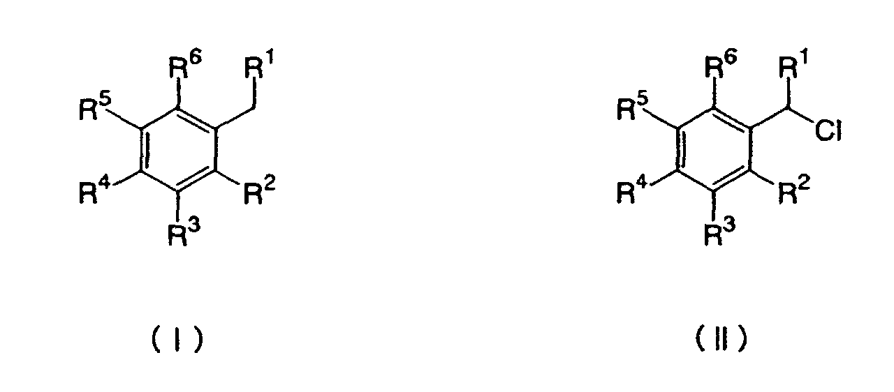
- The process for halogenation of benzene or benzene derivatives as claimed in claim 21, wherein the benzene or benzene derivative halide is a haloalkylbenzene derivative of the following general formula (I) and the impurity is an α-haloalkylbenzene derivative of the following general formula (II):(in formula (I), the groups R1 to R6 are independent of each other; R1 represents a hydrogen atom; R2 to R6 each represent a hydrogen atom, a chlorine atom, or a methyl group, and at least one of these groups is a chlorine atom or a methyl group; in formula (II), the groups R1 to R6 are independent of each other; R1 represents a hydrogen atom; R2 to R6 each represent a hydrogen atom, a chlorine atom, a methyl group or an α-chloromethyl group, and at least one of these groups is a chlorine atom, a hydrogen atom or a methyl group.)

- The process for halogenation of benzene or benzene derivatives as claimed in any one of claims 1 to 25, wherein, in the step of separating zeolite from the zeolite-containing, anhydrous liquid-phase reaction liquid after the reaction, water is added to the anhydrous liquid-phase reaction liquid so as to aggregate the dispersed zeolite, and then this is introduced into a solid-liquid separator so as to separate the zeolite catalyst from it.
Applications Claiming Priority (5)
| Application Number | Priority Date | Filing Date | Title |
|---|---|---|---|
| JP2002152458 | 2002-05-27 | ||
| JP2002152458 | 2002-05-27 | ||
| JP2002214927 | 2002-07-24 | ||
| JP2002214927 | 2002-07-24 | ||
| PCT/JP2003/006464 WO2003099748A1 (en) | 2002-05-27 | 2003-05-23 | Process for halogenation of benzene and benzene derivatives |
Publications (2)
| Publication Number | Publication Date |
|---|---|
| EP1508557A1 true EP1508557A1 (en) | 2005-02-23 |
| EP1508557A4 EP1508557A4 (en) | 2006-05-31 |
Family
ID=29585980
Family Applications (1)
| Application Number | Title | Priority Date | Filing Date |
|---|---|---|---|
| EP03730606A Withdrawn EP1508557A4 (en) | 2002-05-27 | 2003-05-23 | BENZ NE AND BENZ NE D RIV S HALOGEN |
Country Status (4)
| Country | Link |
|---|---|
| US (1) | US20050177010A1 (en) |
| EP (1) | EP1508557A4 (en) |
| AU (1) | AU2003242429A1 (en) |
| WO (1) | WO2003099748A1 (en) |
Families Citing this family (1)
| Publication number | Priority date | Publication date | Assignee | Title |
|---|---|---|---|---|
| CN102603470A (en) * | 2012-02-21 | 2012-07-25 | 南通市东昌化工有限公司 | Production method of 3,4-toluene dichloride |
Family Cites Families (9)
| Publication number | Priority date | Publication date | Assignee | Title |
|---|---|---|---|---|
| US2956084A (en) * | 1959-03-27 | 1960-10-11 | Exxon Research Engineering Co | Process for chlorinating hydrocarbons using chlorine adsorbed on zeolite |
| DE3371503D1 (en) * | 1982-12-22 | 1987-06-19 | Ihara Chemical Ind Co | Process for preparation of nuclear halides of monoalkylbenzenes |
| JPS59163329A (en) * | 1983-03-07 | 1984-09-14 | Ihara Chem Ind Co Ltd | Production of dihalogenated benzene |
| DE3561389D1 (en) * | 1984-03-07 | 1988-02-18 | Ihara Chemical Ind Co | Process for producing a halobenzene |
| JPH0817944B2 (en) * | 1986-12-29 | 1996-02-28 | 東ソー株式会社 | Zeolite catalyst compact for liquid phase organic reaction |
| JPH06321822A (en) * | 1993-05-11 | 1994-11-22 | Nippon Light Metal Co Ltd | Production of p-dichlorobenzene and catalyst for nuclear chlorinating reaction |
| FR2761983B1 (en) * | 1997-04-10 | 1999-06-25 | Atochem Elf Sa | PROCESS FOR THE PURIFICATION OF CHLORINATED AROMATIC HYDROCARBONS |
| JP2000128811A (en) * | 1998-10-26 | 2000-05-09 | Mitsubishi Chemicals Corp | Method for producing parachloroethylbenzene |
| JP2000128810A (en) * | 1998-10-26 | 2000-05-09 | Mitsubishi Chemicals Corp | Production method of parachloroethylbenzene |
-
2003
- 2003-05-23 US US10/515,781 patent/US20050177010A1/en not_active Abandoned
- 2003-05-23 WO PCT/JP2003/006464 patent/WO2003099748A1/en not_active Ceased
- 2003-05-23 EP EP03730606A patent/EP1508557A4/en not_active Withdrawn
- 2003-05-23 AU AU2003242429A patent/AU2003242429A1/en not_active Abandoned
Also Published As
| Publication number | Publication date |
|---|---|
| WO2003099748A1 (en) | 2003-12-04 |
| EP1508557A4 (en) | 2006-05-31 |
| US20050177010A1 (en) | 2005-08-11 |
| AU2003242429A1 (en) | 2003-12-12 |
Similar Documents
| Publication | Publication Date | Title |
|---|---|---|
| DeCastro et al. | Immobilised ionic liquids as Lewis acid catalysts for the alkylation of aromatic compounds with dodecene | |
| EP0171265B1 (en) | Process for preparing halogenated benzene derivatives | |
| EP0231133B1 (en) | Process for preparing para-substituted halogenobenzene derivatives | |
| EP0118851A1 (en) | Process for producing a chlorohalobenzene | |
| HU213181B (en) | Catalytic process for the selective alkylation of polycyclic aromatic compounds | |
| US20050177010A1 (en) | Process for halogenation of benzene and benzene derivatives | |
| EP0219586B1 (en) | Method of selective dealkylation of 1,4-dialkylbenzene | |
| EP0334025B2 (en) | Process for the separation of halogenated benzene derivatives | |
| EP1595862B1 (en) | Process for production of iodine compounds and process for production of high-purity 5-iodo-2-methylbenzoic acid | |
| CA1209591A (en) | Process for isomerizing a halogenated toluene | |
| KR100973879B1 (en) | Manufacturing method of adamantanes | |
| US6462248B1 (en) | Method for producing aromatic compounds having alkyl group with at least three carbon atoms | |
| CA1275115A (en) | Process for producing a halogenated benzene derivative using an improved zeolite catalyst | |
| JP7846001B2 (en) | Process for processing polyalkyl aromatic hydrocarbons | |
| EP0231569B1 (en) | Selective catalytic dealkylation of 1,4-dialkylbenzenes | |
| JP2004107318A (en) | Method for halogenating benzene and benzene derivatives | |
| JPH0723330B2 (en) | Method for producing dichlorobenzene | |
| JP2004292369A (en) | Preparation of alkyl halide aromatic derivatives | |
| JP2004107317A (en) | Method for halogenating benzene and benzene derivatives | |
| KR20010030976A (en) | Process for electrophilic aromatic substitution | |
| JP2595637B2 (en) | Highly selective production of p-dichlorobenzene | |
| JP4400713B2 (en) | Process for producing 5-iodo-2-methylbenzoic acid | |
| Singh et al. | Selective chlorination of 4-chlorotoluene to 2, 4-dichlorotoluene over zeolite catalysts | |
| JP2595650B2 (en) | Highly selective production method of para-substituted chlorinated benzene derivatives | |
| JPH01128946A (en) | Production of p-substituted halogenated benzene derivative |
Legal Events
| Date | Code | Title | Description |
|---|---|---|---|
| PUAI | Public reference made under article 153(3) epc to a published international application that has entered the european phase |
Free format text: ORIGINAL CODE: 0009012 |
|
| 17P | Request for examination filed |
Effective date: 20041126 |
|
| AK | Designated contracting states |
Kind code of ref document: A1 Designated state(s): AT BE BG CH CY CZ DE DK EE ES FI FR GB GR HU IE IT LI LU MC NL PT RO SE SI SK TR |
|
| AX | Request for extension of the european patent |
Extension state: AL LT LV MK |
|
| DAX | Request for extension of the european patent (deleted) | ||
| A4 | Supplementary search report drawn up and despatched |
Effective date: 20060413 |
|
| STAA | Information on the status of an ep patent application or granted ep patent |
Free format text: STATUS: THE APPLICATION IS DEEMED TO BE WITHDRAWN |
|
| 18D | Application deemed to be withdrawn |
Effective date: 20071204 |