EP1508504A2 - Vehicle-direction estimating device and drive control device including it - Google Patents
Vehicle-direction estimating device and drive control device including it Download PDFInfo
- Publication number
- EP1508504A2 EP1508504A2 EP04255034A EP04255034A EP1508504A2 EP 1508504 A2 EP1508504 A2 EP 1508504A2 EP 04255034 A EP04255034 A EP 04255034A EP 04255034 A EP04255034 A EP 04255034A EP 1508504 A2 EP1508504 A2 EP 1508504A2
- Authority
- EP
- European Patent Office
- Prior art keywords
- vehicle
- control device
- curvature
- radius
- planning route
- Prior art date
- Legal status (The legal status is an assumption and is not a legal conclusion. Google has not performed a legal analysis and makes no representation as to the accuracy of the status listed.)
- Granted
Links
Images



Classifications
-
- B—PERFORMING OPERATIONS; TRANSPORTING
- B62—LAND VEHICLES FOR TRAVELLING OTHERWISE THAN ON RAILS
- B62D—MOTOR VEHICLES; TRAILERS
- B62D6/00—Arrangements for automatically controlling steering depending on driving conditions sensed and responded to, e.g. control circuits
- B62D6/001—Arrangements for automatically controlling steering depending on driving conditions sensed and responded to, e.g. control circuits the torque NOT being among the input parameters
-
- B—PERFORMING OPERATIONS; TRANSPORTING
- B60—VEHICLES IN GENERAL
- B60T—VEHICLE BRAKE CONTROL SYSTEMS OR PARTS THEREOF; BRAKE CONTROL SYSTEMS OR PARTS THEREOF, IN GENERAL; ARRANGEMENT OF BRAKING ELEMENTS ON VEHICLES IN GENERAL; PORTABLE DEVICES FOR PREVENTING UNWANTED MOVEMENT OF VEHICLES; VEHICLE MODIFICATIONS TO FACILITATE COOLING OF BRAKES
- B60T8/00—Arrangements for adjusting wheel-braking force to meet varying vehicular or ground-surface conditions, e.g. limiting or varying distribution of braking force
- B60T8/17—Using electrical or electronic regulation means to control braking
- B60T8/172—Determining control parameters used in the regulation, e.g. by calculations involving measured or detected parameters
-
- B—PERFORMING OPERATIONS; TRANSPORTING
- B62—LAND VEHICLES FOR TRAVELLING OTHERWISE THAN ON RAILS
- B62D—MOTOR VEHICLES; TRAILERS
- B62D6/00—Arrangements for automatically controlling steering depending on driving conditions sensed and responded to, e.g. control circuits
- B62D6/002—Arrangements for automatically controlling steering depending on driving conditions sensed and responded to, e.g. control circuits computing target steering angles for front or rear wheels
-
- G—PHYSICS
- G01—MEASURING; TESTING
- G01C—MEASURING DISTANCES, LEVELS OR BEARINGS; SURVEYING; NAVIGATION; GYROSCOPIC INSTRUMENTS; PHOTOGRAMMETRY OR VIDEOGRAMMETRY
- G01C21/00—Navigation; Navigational instruments not provided for in groups G01C1/00 - G01C19/00
- G01C21/26—Navigation; Navigational instruments not provided for in groups G01C1/00 - G01C19/00 specially adapted for navigation in a road network
- G01C21/28—Navigation; Navigational instruments not provided for in groups G01C1/00 - G01C19/00 specially adapted for navigation in a road network with correlation of data from several navigational instruments
-
- B—PERFORMING OPERATIONS; TRANSPORTING
- B60—VEHICLES IN GENERAL
- B60T—VEHICLE BRAKE CONTROL SYSTEMS OR PARTS THEREOF; BRAKE CONTROL SYSTEMS OR PARTS THEREOF, IN GENERAL; ARRANGEMENT OF BRAKING ELEMENTS ON VEHICLES IN GENERAL; PORTABLE DEVICES FOR PREVENTING UNWANTED MOVEMENT OF VEHICLES; VEHICLE MODIFICATIONS TO FACILITATE COOLING OF BRAKES
- B60T2210/00—Detection or estimation of road or environment conditions; Detection or estimation of road shapes
- B60T2210/30—Environment conditions or position therewithin
- B60T2210/36—Global Positioning System [GPS]
-
- B—PERFORMING OPERATIONS; TRANSPORTING
- B60—VEHICLES IN GENERAL
- B60W—CONJOINT CONTROL OF VEHICLE SUB-UNITS OF DIFFERENT TYPE OR DIFFERENT FUNCTION; CONTROL SYSTEMS SPECIALLY ADAPTED FOR HYBRID VEHICLES; ROAD VEHICLE DRIVE CONTROL SYSTEMS FOR PURPOSES NOT RELATED TO THE CONTROL OF A PARTICULAR SUB-UNIT
- B60W50/00—Details of control systems for road vehicle drive control not related to the control of a particular sub-unit, e.g. process diagnostic or vehicle driver interfaces
- B60W50/04—Monitoring the functioning of the control system
- B60W50/045—Monitoring control system parameters
- B60W2050/046—Monitoring control system parameters involving external transmission of data to or from the vehicle, e.g. via telemetry, satellite, Global Positioning System [GPS]
-
- B—PERFORMING OPERATIONS; TRANSPORTING
- B60—VEHICLES IN GENERAL
- B60W—CONJOINT CONTROL OF VEHICLE SUB-UNITS OF DIFFERENT TYPE OR DIFFERENT FUNCTION; CONTROL SYSTEMS SPECIALLY ADAPTED FOR HYBRID VEHICLES; ROAD VEHICLE DRIVE CONTROL SYSTEMS FOR PURPOSES NOT RELATED TO THE CONTROL OF A PARTICULAR SUB-UNIT
- B60W2552/00—Input parameters relating to infrastructure
- B60W2552/20—Road profile, i.e. the change in elevation or curvature of a plurality of continuous road segments
-
- B—PERFORMING OPERATIONS; TRANSPORTING
- B60—VEHICLES IN GENERAL
- B60W—CONJOINT CONTROL OF VEHICLE SUB-UNITS OF DIFFERENT TYPE OR DIFFERENT FUNCTION; CONTROL SYSTEMS SPECIALLY ADAPTED FOR HYBRID VEHICLES; ROAD VEHICLE DRIVE CONTROL SYSTEMS FOR PURPOSES NOT RELATED TO THE CONTROL OF A PARTICULAR SUB-UNIT
- B60W2552/00—Input parameters relating to infrastructure
- B60W2552/30—Road curve radius
-
- B—PERFORMING OPERATIONS; TRANSPORTING
- B60—VEHICLES IN GENERAL
- B60W—CONJOINT CONTROL OF VEHICLE SUB-UNITS OF DIFFERENT TYPE OR DIFFERENT FUNCTION; CONTROL SYSTEMS SPECIALLY ADAPTED FOR HYBRID VEHICLES; ROAD VEHICLE DRIVE CONTROL SYSTEMS FOR PURPOSES NOT RELATED TO THE CONTROL OF A PARTICULAR SUB-UNIT
- B60W30/00—Purposes of road vehicle drive control systems not related to the control of a particular sub-unit, e.g. of systems using conjoint control of vehicle sub-units
- B60W30/08—Active safety systems predicting or avoiding probable or impending collision or attempting to minimise its consequences
- B60W30/09—Taking automatic action to avoid collision, e.g. braking and steering
Definitions
- the present invention relates to a direction-estimating device for a vehicle for estimating the direction of the vehicle based upon the position of the vehicle calculated based upon signals from artificial satellites and a planning route set on a map or the like, and to a driving control device including the aforementioned direction-estimating device.
- GPS Global Positioning System
- a device is disclosed in Japanese Unexamined Patent Application Publication No. 2003-26017, wherein the position of the vehicle is calculated based upon information from the GPS, a planning route along which the vehicle is to be driven is calculated, and the viewing distance is computed based upon the steering-frequency response.
- the future-position lateral deviation of the vehicle corresponding to the viewing-distance point from the planning route is computed based upon the moving vector of the vehicle, and the current-position lateral deviation of the vehicle from the planning route is computed.
- the target amount-of-change of steering angle is computed based upon the aforementioned current-position lateral deviation and future-position lateral deviation for steering such that the vehicle follows the planning route, whereby steering is made according to the command value determined based upon the computed target amount-of-change of steering angle.
- the future-position lateral deviation is computed based upon the moving vector of the vehicle. Accordingly, the moving vector of the vehicle calculated with inaccuracy leads to the future-position lateral deviation with insufficient precision, resulting in automatic steering with insufficient precision.
- the present invention has been made in order to solve the aforementioned problems, and accordingly, it is an object thereof to provide a direction-estimating device for precisely estimating the direction of the vehicle appropriately corresponding to each driving situation, and a driving-control device including the aforementioned direction-estimating device, thereby enabling precise and stable control of driving of the vehicle.
- a direction estimating device for a vehicle comprises: first vehicle-position detecting means for detecting a first position of the vehicle based upon information received from satellites orbiting the Earth; second vehicle-position detecting means for detecting a second position of the vehicle, differing from the first position of the vehicle, based upon information received from the satellites orbiting the Earth; planning-route setting means for setting a planning route which the vehicle is to be driven; radius-of-curvature computing means for computing the radius of curvature of the planning route; and vehicle-direction estimating means for estimating the direction of the vehicle based upon the moving vector of the vehicle plotted by the first position and the second position in a case of the radius of curvature of the planning route less than a predetermined threshold.
- a GPS known as a RTK (Real-Time Kinetic) GPS is employed. That is to say, the information (data such as satellite-orbit information for performing positioning calculation and so forth) from artificial satellites (GPS satellites) 1 orbiting the Earth is received by a base station 2 and a vehicle 3 serving as a moving station (including two receivers, as described later).
- RTK Real-Time Kinetic
- the base station 2 is installed at a position which has been measured beforehand with sufficient precision, and principally includes a GPS antenna 2a, a GPS receiver 2b, and a wireless communication device 2c.
- the base station 2 transmits the phase information with regard to the radio wave from the GPS satellites 1, the pseudo range, and the position coordinates of the base station 2, to a point which is to be measured, i.e., the vehicle 3 including two receivers serving as the moving station, using the wireless communication device 2c.
- the data transmitted from the base station 2 to the vehicle 3 includes: error correction data; pseudo-range correction data; and the position coordinates of the base station 2.
- the vehicle 3 includes a GPS antenna 3a, a GPS receiver 3b, and a wireless communication device 3c, on a front portion along the longitudinal direction and generally on the middle portion along the lateral direction in the vehicle interior. Furthermore, the vehicle 3 includes a GPS antenna 3d, a GPS receiver 3e, and a wireless communication device 3f, on a rear portion along the longitudinal direction and generally on the middle portion along the lateral direction in the vehicle interior. Note that the GPS antennas 3a and 3d are disposed away from one another so as to detect the difference between the positions thereof, giving consideration to the margin of error of the RTK-GPS. For example, with the RTK-GPS with a maximum margin of error of 5 cm, the GPS antennas 3a and 3d are disposed on the front and rear portions 10 cm or more away from one another.
- the front GPS receiver 3b calculates the position (position coordinates) of the front portion of the vehicle with high precision (e.g., margin of error of 1 to 5 cm) in real time by analyzing the error correction data, the pseudo-range correction data, and the position coordinates of the base station 2, received from the base station 2 (data received through the wireless communication device 3c) and the information directly received from the GPS satellites 1.
- the GPS receiver 3b has a function as first vehicle-position detecting means for detecting a first position (i.e., the position of the GPS antenna 3a disposed on the front portion) of the vehicle.
- the rear GPS receiver 3e calculates the position (position coordinates) of the rear portion of the vehicle with high precision (e.g., margin of error of 1 to 5 cm) in real time by analyzing the error correction data, the pseudo-range correction data, and the position coordinates of the base station 2, received from the base station 2 (data received through the wireless communication device 3f) and the information directly received from the GPS satellites 1.
- the GPS receiver 3e has a function as second vehicle-position detecting means for detecting a second position (i.e., the position of the GPS antenna 3d disposed on the rear portion) of the vehicle.
- the position of the front portion of the vehicle is obtained by actions of the GPS antenna 3a, the GPS receiver 3b, and the wireless communication device 3c
- the position of the rear portion of the vehicle is obtained by actions of the GPS antenna 3d, the GPS receiver 3e, and the wireless communication device 3f.
- the position of the front portion of the vehicle represents the position of the vehicle.
- the vehicle 3 includes planning-route setting means, radius-of-curvature computing means, vehicle-direction estimating means, and a control device 3g having a function as vehicle-control-information computing means.
- the control device 3g is connected to the front GPS receiver 3b and the rear GPS receiver 3e through an unshown serial-CAN converter or the like for receiving the information with regard to the current positions of the front and rear portions of the vehicle.
- the control device 3g is connected to sensors such as a speed sensor 3h for detecting the speed V of the vehicle, a steering-angle sensor 3i for detecting the steering angle ⁇ H, and so forth, and a main switch 3j for switching to an automatic-driving control mode.
- control device 3g of the vehicle 3 includes an unshown storage medium such as a hard disk, CD, DVD, or the like, which has map information stored therein necessary for the automatic-driving control.
- the map information is suitably displayed on a liquid crystal display 3k mounted on a dash board thereof, for example.
- the current vehicle position and the optimum route (the planning route which a node line yields) from the current position to the destination are displayed on a map shown on the liquid crystal display 3k.
- control device 3g of the vehicle 3 is connected to actuators for performing the automatic-driving control, such as an electric throttle control device 31, a brake control device 3m, and an electric power steering control device 3n.
- the control device 3g Upon the user turning on the main switch 3j for switching to the automatic-driving control mode, and setting the speed of the vehicle in the automatic-driving control mode, the control device 3g outputs signals to the electric throttle control device 31 so as to drive a throttle 3o such that the vehicle is accelerated or decelerated in order to maintain the set speed of the vehicle. Furthermore, in the event that deceleration of the vehicle must be made beyond a predetermined deceleration, the control device 3g outputs signals to the brake control device 3m so as to operate automatic braking.
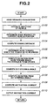
- Step 101 the control device 3g reads the required parameters.
- the control device 3g estimates the direction of the vehicle according to a vehicle-direction estimating routine described later.
- the control device 3g extracts the direction of the vehicle to be the direction passing through the positions of the front and rear portions of the vehicle, or the previous position of the vehicle, approximately the length of the vehicle (e.g., 5m) behind the current position (the current position of the front portion thereof) from vehicle-position-history information and estimates the direction of the vehicle to be the direction passing through the current position of the vehicle and the previous position thereof, 5m behind the current position thereof.
- a predetermined viewing time e.g. 1.5 sec.
- the flow proceeds to S105, where the control device 3d determines a node on the planning route, which is approximately the viewing distance calculated in S104 in front of the current position of the vehicle, and sets the node thus determined as a node toward which the vehicle is to be driven.
- control device 3g computes the lateral deviation of the direction of the vehicle from the node toward which the vehicle is to be driven, as the node deviation ⁇ D.
- Gp represents a proportional gain
- Gd represents a differential gain
- Kp is a proportional gain
- Kd is a differential gain
- Ki is an integral gain
- the control device 3g computes the radius of curvature R of the planning route.
- the radius of curvature R can be obtained by calculating the radius of the circle passing through the three nodes on the planning route.
- the control device 3g may select: the node toward which the vehicle is heading, and the nodes adjacent to the aforementioned node; the node nearest to the current position of the vehicle and the nodes adjacent to the nearest nodes; or the node at a position, the predetermined viewing distance in front of the current vehicle position, and the nodes adjacent to the aforementioned node.
- the control device 3g selects the node toward which the vehicle is heading, and the nodes adjacent to the nearest node.
- the control device 3g selects three nodes of P1(x1, y1), P2(x2, y2), and P3(x3, y3), in the coordinate space of X and Y.
- the X axis represents the lateral direction of the vehicle 3
- the Y axis represents the longitudinal direction thereof.
- Sa represents the area of the triangle P1-P2-P3, and is calculated by Expression (4) described below.
- Sa ( ⁇ • ( ⁇ - A) • ( ⁇ - B) • ( ⁇ - C)) 1/2
- ⁇ represents (A + B + C)/2.
- the control device 3g sets the radius of curvature Rc as a predetermined threshold.
- the radius of curvature Rc is determined corresponding to the vehicle speed V. For example, the greater the vehicle speed V is, the greater the radius of curvature is determined as shown in the relation in Fig. 6.
- the control device 3g may correct the radius of curvature Rc corresponding to situations such as the width of the road and so forth. For example, the control device 3g adds a small correction value to the radius of curvature Rc in a case of a wide road such as an expressway, national road, or the like, based upon map information or the like stored therein. Otherwise, the control device 3g adds a great correction value to the radius of curvature Rc.
- the flow proceeds to S203, where the control device 3g makes a comparison between the radius of curvature R of the planning route and the threshold of the radius of curvature Rc.
- the control device 3g estimates the direction of the vehicle to be the direction passing through the positions of the front and rear portions of the vehicle, whereby the routine ends.
- the flow proceeds to S205, where the control device 3g extracts the previous position of the vehicle, approximately the length of the vehicle (e.g., 5m) behind the current position (the current position of the front portion thereof) from vehicle-position-history information and estimates the direction of the vehicle to be the direction passing through the current vehicle position and the previous vehicle position, approximately the length of the vehicle (e.g., 5 m) behind the current vehicle position, whereby the routine ends.
- the control device 3g extracts the previous position of the vehicle, approximately the length of the vehicle (e.g., 5m) behind the current position (the current position of the front portion thereof) from vehicle-position-history information and estimates the direction of the vehicle to be the direction passing through the current vehicle position and the previous vehicle position, approximately the length of the vehicle (e.g., 5 m) behind the current vehicle position, whereby the routine ends.
- the control device 3g estimates the direction of the vehicle to be the direction passing through the current vehicle position and the previous vehicle position, approximately the length of the vehicle behind the current vehicle position, for the planning route with a small radius of curvature R, there is a problem that the direction of the vehicle 3 may differ between these two positions, leading to a problem that the node deviation ⁇ D from the node toward which the vehicle is to be driven may be calculated with insufficient precision. Accordingly, in this case, the control device 3g estimates the direction of the vehicle to be the direction passing through the positions of the front and rear portions of the vehicle.
- the control device 3g estimates the direction of the vehicle to be the direction passing through the positions of the front and rear portions of the vehicle for the planning route with a large radius of curvature R, slight deviation due to a slight yaw angle occurring in the vehicle 3 is precisely calculated into a significant value. This leads to a margin of error contained in the steering angle Sh calculated based upon the node deviation ⁇ D from the node toward which the vehicle is to be driven, resulting in undesirable fluctuation in steering of the vehicle (deterioration in straight-driving stability). Accordingly, in this case, the control device 3g estimates the direction of the vehicle to be the direction passing through the current vehicle position and the previous vehicle position, approximately the length of the vehicle behind the current vehicle position.
- the control device 3g estimates the direction of the vehicle to be the direction passing through the positions of the front and rear portions of the vehicle for the planning route with a small radius of curvature R, and estimates the direction of the vehicle to be the direction passing through the current vehicle position and the previous vehicle position, approximately the length of the vehicle behind the current vehicle position, for the planning route with a large radius of curvature R, thereby enabling precise estimation of the direction of the vehicle appropriately corresponding to each driving situation.
- driving of the vehicle is controlled based upon the current vehicle position and the planning route using the estimated direction of the vehicle, thereby enabling stable and precise control of driving of the vehicle.
- the present invention is not restricted to the aforementioned arrangement, rather, the GPS antennas 3a and 3d may be disposed away from one another along the lateral direction. Furthermore, the GPS antennas 3a and 3d may be disposed away from one another on the outside of the vehicle (e.g., disposed within front and rear bumpers). Furthermore, the GPS antennas 3a and 3d may be disposed at any positions away from one another as long as the control device 3g can detect the difference between the positions thereof, and the direction of the vehicle as to the line passing through the positions.
- the present invention enables suitable and precise estimation of the direction of the vehicle corresponding to each driving situation of the vehicle, thereby enabling precise and stable driving control.
Landscapes
- Engineering & Computer Science (AREA)
- Radar, Positioning & Navigation (AREA)
- Remote Sensing (AREA)
- Mechanical Engineering (AREA)
- Transportation (AREA)
- Chemical & Material Sciences (AREA)
- Combustion & Propulsion (AREA)
- Physics & Mathematics (AREA)
- General Physics & Mathematics (AREA)
- Automation & Control Theory (AREA)
- Mathematical Physics (AREA)
- Steering Control In Accordance With Driving Conditions (AREA)
- Navigation (AREA)
- Traffic Control Systems (AREA)
- Control Of Driving Devices And Active Controlling Of Vehicle (AREA)
Abstract
Description
Claims (6)
- A direction estimating device for a vehicle, comprising:first vehicle-position detecting means (3b) for detecting a first position of the vehicle (3) based upon information received from satellites (1) orbiting the Earth;second vehicle-position detecting means (3e) for detecting a second position of the vehicle (3), differing from the first position of the vehicle (3), based upon information received from the satellites (1) orbiting the Earth;planning-route setting means (3g) for setting a planning route which the vehicle is to be driven;radius-of-curvature computing means (3g) for computing the radius of curvature of the planning route; andvehicle-direction estimating means (3g) for estimating the direction of the vehicle (3) to be the direction passing through the first position and the second position in a case of the radius of curvature of the planning route less than a predetermined threshold.
- The direction estimating device for the vehicle according to Claim 1, further comprising vehicle-movement-information computing means (3g) for computing information with regard to movement of the vehicle up to the current position thereof based upon change of the first position or the second position over time,
wherein the vehicle-direction estimating means (3g) estimate the direction of the vehicle (3) by calculating the moving direction of the vehicle based upon the information with regard to movement of the vehicle (3) in a case of the radius of curvature of the planning route exceeding the predetermined threshold. - The direction estimating device for the vehicle according to Claim 2, wherein the vehicle-direction estimating means estimate the moving direction of the vehicle to be the direction passing through the current vehicle position and the previous vehicle position, approximately the length of the vehicle (3) behind the current vehicle position, in the event that the vehicle-direction estimating means (3g) estimate the moving direction of the vehicle (3) based upon the information with regard to movement of the vehicle position.
- The direction estimating device for the vehicle according to any one of Claims 1 to 3, wherein the predetermined threshold is changed corresponding to the speed of the vehicle.
- A driving control device for a vehicle comprising a direction estimating device for a vehicle according to any one of Claims 1 to 4, wherein driving of the vehicle (3) is controlled based upon the current position of the vehicle, the estimated direction of the vehicle, and the planning route.
- A vehicle comprising a direction estimating device as claimed in any of Claims 1 to 4 or comprising a driving control device as claimed in Claim 5.
Applications Claiming Priority (2)
| Application Number | Priority Date | Filing Date | Title |
|---|---|---|---|
| JP2003297997 | 2003-08-21 | ||
| JP2003297997A JP4230312B2 (en) | 2003-08-21 | 2003-08-21 | VEHICLE PATH ESTIMATION DEVICE AND TRAVEL CONTROL DEVICE EQUIPPED WITH THE PATH ESTIMATION DEVICE |
Publications (3)
| Publication Number | Publication Date |
|---|---|
| EP1508504A2 true EP1508504A2 (en) | 2005-02-23 |
| EP1508504A3 EP1508504A3 (en) | 2006-07-05 |
| EP1508504B1 EP1508504B1 (en) | 2011-05-25 |
Family
ID=34056254
Family Applications (1)
| Application Number | Title | Priority Date | Filing Date |
|---|---|---|---|
| EP04255034A Expired - Lifetime EP1508504B1 (en) | 2003-08-21 | 2004-08-20 | Vehicle-direction estimating device and drive control device including it |
Country Status (3)
| Country | Link |
|---|---|
| US (1) | US7164985B2 (en) |
| EP (1) | EP1508504B1 (en) |
| JP (1) | JP4230312B2 (en) |
Cited By (2)
| Publication number | Priority date | Publication date | Assignee | Title |
|---|---|---|---|---|
| CN103442970A (en) * | 2011-03-23 | 2013-12-11 | 丰田自动车株式会社 | Vehicle information processing device |
| EP3344479A4 (en) * | 2016-09-27 | 2018-10-10 | Baidu USA LLC | A vehicle position point forwarding method for autonomous vehicles |
Families Citing this family (20)
| Publication number | Priority date | Publication date | Assignee | Title |
|---|---|---|---|---|
| US8080257B2 (en) | 2000-12-12 | 2011-12-20 | L'oreal S.A. | Cosmetic compositions containing at least one hetero polymer and at least one film-forming silicone resin and methods of using |
| US8214111B2 (en) * | 2005-07-19 | 2012-07-03 | Hemisphere Gps Llc | Adaptive machine control system and method |
| US9002565B2 (en) | 2003-03-20 | 2015-04-07 | Agjunction Llc | GNSS and optical guidance and machine control |
| US8634993B2 (en) | 2003-03-20 | 2014-01-21 | Agjunction Llc | GNSS based control for dispensing material from vehicle |
| DE112006002182B4 (en) * | 2005-08-18 | 2010-08-05 | Sauer-Danfoss Aps | A method of calibrating a steering system and steering a vehicle with a positioning system |
| WO2007143806A2 (en) * | 2006-06-15 | 2007-12-21 | Uti Limited Partnership | Vehicular navigation and positioning system |
| JP4983132B2 (en) * | 2006-07-26 | 2012-07-25 | 株式会社デンソー | Vehicle direction identification method and vehicle direction identification device. |
| US7855678B2 (en) * | 2007-05-16 | 2010-12-21 | Trimble Navigation Limited | Post-mission high accuracy position and orientation system |
| US20090093959A1 (en) * | 2007-10-04 | 2009-04-09 | Trimble Navigation Limited | Real-time high accuracy position and orientation system |
| US9173337B2 (en) | 2009-10-19 | 2015-11-03 | Efc Systems, Inc. | GNSS optimized control system and method |
| SE534220C2 (en) | 2009-10-22 | 2011-06-07 | Scania Cv Ab | Automatic friction estimation |
| KR101145112B1 (en) | 2010-05-11 | 2012-05-14 | 국방과학연구소 | Steering control device of autonomous vehicle, autonomous vehicle having the same and steering control method of autonomous vehicle |
| JP5429062B2 (en) | 2010-06-11 | 2014-02-26 | トヨタ自動車株式会社 | Vehicle travel control device |
| RU2659341C2 (en) * | 2013-04-01 | 2018-06-29 | Су-Мин ПАРК | Vehicle automatic control system |
| KR101534958B1 (en) * | 2013-12-09 | 2015-07-07 | 현대자동차주식회사 | Apparatus and Method for Controlling of Automatic Steering of Vehicle |
| US9644972B2 (en) * | 2015-03-06 | 2017-05-09 | Tallysman Wireless Inc. | Method for tracking a path taken by a vehicle |
| JP6567936B2 (en) * | 2015-09-30 | 2019-08-28 | 株式会社Subaru | Steering support control device |
| DE102016209778A1 (en) * | 2016-06-03 | 2017-12-07 | Robert Bosch Gmbh | Method and device for carrying out a diagnosis |
| US10831195B2 (en) * | 2016-06-29 | 2020-11-10 | Nidec Corporation | Mobile body guidance system, mobile body, guidance device, and computer program |
| DE102019100642A1 (en) | 2018-01-16 | 2019-07-18 | Aisin Seiki Kabushiki Kaisha | Position detection system and processing device |
Family Cites Families (12)
| Publication number | Priority date | Publication date | Assignee | Title |
|---|---|---|---|---|
| FR2656435B1 (en) * | 1989-12-22 | 1996-07-05 | Commissariat Energie Atomique | RECORDING METHOD ON A THEORETICAL TRAJECTORY FOR A VEHICLE BY MODIFYING THE CURVATURE OF THE ACTUAL TRAJECTORY. |
| US5471385A (en) * | 1992-05-21 | 1995-11-28 | Tsubakimoto Chain Co. | Routeless guiding method for moving body |
| US5854987A (en) * | 1995-02-22 | 1998-12-29 | Honda Giken Kogyo Kabushiki Kaisha | Vehicle steering control system using navigation system |
| DE19521358C1 (en) * | 1995-06-12 | 1996-09-05 | Siemens Ag | Slip detection system for 3-wheeled autonomous mobile unit |
| US5729457A (en) * | 1995-07-10 | 1998-03-17 | Motorola, Inc. | Route entry location apparatus |
| US6266582B1 (en) * | 1997-08-06 | 2001-07-24 | Rockwell Collins. Inc. | GPS analytic redundancy for gyroscope failure detection |
| JP4021027B2 (en) * | 1998-01-29 | 2007-12-12 | 富士重工業株式会社 | Travel route recognition device |
| DE19829582C1 (en) | 1998-07-02 | 2000-03-09 | Daimler Chrysler Ag | Rotation rate measuring method, e.g. for transverse rotation in automobile; compares output signal of rotation rate sensor with differential of angle sensor signal for zero point drift compensation |
| US6681180B2 (en) * | 2001-01-29 | 2004-01-20 | The Board Of Trustees Of The Leland Stanford Junior University | Determination and control of vehicle sideslip using GPS |
| DE10148667C2 (en) | 2001-06-14 | 2003-06-18 | Bosch Gmbh Robert | Method for determining a vector vehicle speed |
| JP4639545B2 (en) | 2001-07-19 | 2011-02-23 | 日産自動車株式会社 | Vehicle steering control device |
| US6671587B2 (en) * | 2002-02-05 | 2003-12-30 | Ford Motor Company | Vehicle dynamics measuring apparatus and method using multiple GPS antennas |
-
2003
- 2003-08-21 JP JP2003297997A patent/JP4230312B2/en not_active Expired - Fee Related
-
2004
- 2004-08-20 US US10/923,426 patent/US7164985B2/en not_active Expired - Lifetime
- 2004-08-20 EP EP04255034A patent/EP1508504B1/en not_active Expired - Lifetime
Cited By (3)
| Publication number | Priority date | Publication date | Assignee | Title |
|---|---|---|---|---|
| CN103442970A (en) * | 2011-03-23 | 2013-12-11 | 丰田自动车株式会社 | Vehicle information processing device |
| CN103442970B (en) * | 2011-03-23 | 2015-08-19 | 丰田自动车株式会社 | Vehicle information processing device |
| EP3344479A4 (en) * | 2016-09-27 | 2018-10-10 | Baidu USA LLC | A vehicle position point forwarding method for autonomous vehicles |
Also Published As
| Publication number | Publication date |
|---|---|
| JP4230312B2 (en) | 2009-02-25 |
| US20050043882A1 (en) | 2005-02-24 |
| JP2005070983A (en) | 2005-03-17 |
| EP1508504B1 (en) | 2011-05-25 |
| EP1508504A3 (en) | 2006-07-05 |
| US7164985B2 (en) | 2007-01-16 |
Similar Documents
| Publication | Publication Date | Title |
|---|---|---|
| EP1508504A2 (en) | Vehicle-direction estimating device and drive control device including it | |
| EP1508505B1 (en) | Driving control device for vehicle | |
| JP3449240B2 (en) | Vehicle current position detection device, vehicle current position display device, navigation device, and recording medium | |
| US5926117A (en) | Vehicle control system, vehicle mounting apparatus, base station apparatus and vehicle control method | |
| JP3467136B2 (en) | Travel control device for autonomous vehicles | |
| EP1178329B1 (en) | Method of and apparatus for correcting the position of movable body in navigation system | |
| EP1818682A1 (en) | Position calculating apparatus | |
| EP2108923A2 (en) | Mobile terminal having a hybrid navigation system, method for determining a location thereof, and computer-readable recording medium recording the method | |
| GB2286696A (en) | Autonomous vehicle guidance system | |
| EP1542109A1 (en) | Driving control device for a vehicle | |
| CN110441806A (en) | Satellite-based method for vehicle location determination via motion and position sensors | |
| KR20190010267A (en) | Navigation apparatus and method for vehicle, and navigation system | |
| JP2006322753A (en) | Vehicle travel control device | |
| JP2019184566A (en) | Vehicle and vehicle position estimation device | |
| KR102244761B1 (en) | Method and apparatus for providing reliability information for positioning information in autonomous vehicle | |
| JP4346993B2 (en) | Vehicle guidance control device | |
| US6418375B2 (en) | Navigation method using a small volume of data | |
| US7184882B2 (en) | Vehicle navigation system | |
| JP3592436B2 (en) | Moving distance deriving method and apparatus | |
| KR101445872B1 (en) | apparatus and method for estimating position of vehicle usig driving Record | |
| EP1243939B1 (en) | Method and apparatus for reducing vehicle position data based upon data accuracy estimation | |
| JPH07229750A (en) | Navigation device for vehicle | |
| JP3551663B2 (en) | Navigation device | |
| KR20090049501A (en) | Vehicle position correction method and device | |
| KR20130057114A (en) | Dead-reckoning system using education and the method thereof |
Legal Events
| Date | Code | Title | Description |
|---|---|---|---|
| PUAI | Public reference made under article 153(3) epc to a published international application that has entered the european phase |
Free format text: ORIGINAL CODE: 0009012 |
|
| AK | Designated contracting states |
Kind code of ref document: A2 Designated state(s): AT BE BG CH CY CZ DE DK EE ES FI FR GB GR HU IE IT LI LU MC NL PL PT RO SE SI SK TR |
|
| AX | Request for extension of the european patent |
Extension state: AL HR LT LV MK |
|
| PUAL | Search report despatched |
Free format text: ORIGINAL CODE: 0009013 |
|
| AK | Designated contracting states |
Kind code of ref document: A3 Designated state(s): AT BE BG CH CY CZ DE DK EE ES FI FR GB GR HU IE IT LI LU MC NL PL PT RO SE SI SK TR |
|
| AX | Request for extension of the european patent |
Extension state: AL HR LT LV MK |
|
| RIC1 | Information provided on ipc code assigned before grant |
Ipc: B62D 6/00 20060101ALI20060529BHEP Ipc: B60T 8/00 20060101AFI20060529BHEP |
|
| RIC1 | Information provided on ipc code assigned before grant |
Ipc: B62D 6/00 20060101ALI20060602BHEP Ipc: B60W 10/04 20060101ALI20060602BHEP Ipc: B60W 30/10 20060101ALI20060602BHEP Ipc: B60W 10/20 20060101ALI20060602BHEP Ipc: B60T 8/00 20060101AFI20060602BHEP Ipc: B60W 10/18 20060101ALI20060602BHEP |
|
| AKX | Designation fees paid | ||
| 17P | Request for examination filed |
Effective date: 20060724 |
|
| RBV | Designated contracting states (corrected) |
Designated state(s): DE |
|
| 17Q | First examination report despatched |
Effective date: 20070308 |
|
| REG | Reference to a national code |
Ref country code: DE Ref legal event code: 8566 |
|
| GRAP | Despatch of communication of intention to grant a patent |
Free format text: ORIGINAL CODE: EPIDOSNIGR1 |
|
| RIC1 | Information provided on ipc code assigned before grant |
Ipc: B62D 6/00 20060101ALI20101130BHEP Ipc: G01C 21/28 20060101ALI20101130BHEP Ipc: B60T 8/172 20060101AFI20101130BHEP |
|
| RIN1 | Information on inventor provided before grant (corrected) |
Inventor name: TAKAZAWA, ATSUYOSHI,C/O FUJI JUKOGYO KABUSHKI KAIS |
|
| GRAS | Grant fee paid |
Free format text: ORIGINAL CODE: EPIDOSNIGR3 |
|
| GRAA | (expected) grant |
Free format text: ORIGINAL CODE: 0009210 |
|
| AK | Designated contracting states |
Kind code of ref document: B1 Designated state(s): DE |
|
| REG | Reference to a national code |
Ref country code: DE Ref legal event code: R096 Ref document number: 602004032800 Country of ref document: DE Effective date: 20110707 |
|
| PLBE | No opposition filed within time limit |
Free format text: ORIGINAL CODE: 0009261 |
|
| STAA | Information on the status of an ep patent application or granted ep patent |
Free format text: STATUS: NO OPPOSITION FILED WITHIN TIME LIMIT |
|
| 26N | No opposition filed |
Effective date: 20120228 |
|
| REG | Reference to a national code |
Ref country code: DE Ref legal event code: R097 Ref document number: 602004032800 Country of ref document: DE Effective date: 20120228 |
|
| REG | Reference to a national code |
Ref country code: DE Ref legal event code: R082 Ref document number: 602004032800 Country of ref document: DE Representative=s name: W.P.THOMPSON & CO., GB Ref country code: DE Ref legal event code: R081 Ref document number: 602004032800 Country of ref document: DE Owner name: SUBARU CORPORATION, JP Free format text: FORMER OWNER: FUJI JUKOGYO K.K., TOKIO/TOKYO, JP |
|
| PGFP | Annual fee paid to national office [announced via postgrant information from national office to epo] |
Ref country code: DE Payment date: 20190822 Year of fee payment: 16 |
|
| REG | Reference to a national code |
Ref country code: DE Ref legal event code: R119 Ref document number: 602004032800 Country of ref document: DE |
|
| PG25 | Lapsed in a contracting state [announced via postgrant information from national office to epo] |
Ref country code: DE Free format text: LAPSE BECAUSE OF NON-PAYMENT OF DUE FEES Effective date: 20210302 |