EP1508441B1 - Machine d'impression rotative et plieuse en entonnoir - Google Patents
Machine d'impression rotative et plieuse en entonnoir Download PDFInfo
- Publication number
- EP1508441B1 EP1508441B1 EP04105447A EP04105447A EP1508441B1 EP 1508441 B1 EP1508441 B1 EP 1508441B1 EP 04105447 A EP04105447 A EP 04105447A EP 04105447 A EP04105447 A EP 04105447A EP 1508441 B1 EP1508441 B1 EP 1508441B1
- Authority
- EP
- European Patent Office
- Prior art keywords
- web
- machine according
- printing machine
- cylinder
- fed rotary
- Prior art date
- Legal status (The legal status is an assumption and is not a legal conclusion. Google has not performed a legal analysis and makes no representation as to the accuracy of the status listed.)
- Expired - Lifetime
Links
- 238000007639 printing Methods 0.000 title claims abstract description 226
- 238000012546 transfer Methods 0.000 claims abstract description 42
- 238000003825 pressing Methods 0.000 claims description 15
- 230000005540 biological transmission Effects 0.000 claims description 3
- 238000012545 processing Methods 0.000 claims description 2
- 230000004323 axial length Effects 0.000 abstract 1
- 238000005096 rolling process Methods 0.000 description 42
- 239000000047 product Substances 0.000 description 19
- 238000004519 manufacturing process Methods 0.000 description 15
- 230000008901 benefit Effects 0.000 description 8
- 238000005520 cutting process Methods 0.000 description 8
- 238000009826 distribution Methods 0.000 description 8
- 230000008859 change Effects 0.000 description 7
- 239000000725 suspension Substances 0.000 description 7
- 230000001154 acute effect Effects 0.000 description 6
- 238000013461 design Methods 0.000 description 6
- 238000011161 development Methods 0.000 description 5
- 239000000543 intermediate Substances 0.000 description 5
- 239000013067 intermediate product Substances 0.000 description 4
- 238000000034 method Methods 0.000 description 4
- 238000005452 bending Methods 0.000 description 3
- 239000007795 chemical reaction product Substances 0.000 description 3
- 230000000295 complement effect Effects 0.000 description 3
- 239000000463 material Substances 0.000 description 3
- 229910052751 metal Inorganic materials 0.000 description 3
- 239000002184 metal Substances 0.000 description 3
- 238000007645 offset printing Methods 0.000 description 3
- 230000009467 reduction Effects 0.000 description 3
- 239000004575 stone Substances 0.000 description 3
- 238000011144 upstream manufacturing Methods 0.000 description 3
- WYWHKKSPHMUBEB-UHFFFAOYSA-N 6-Mercaptoguanine Natural products N1C(N)=NC(=S)C2=C1N=CN2 WYWHKKSPHMUBEB-UHFFFAOYSA-N 0.000 description 2
- 241000287107 Passer Species 0.000 description 2
- 239000000969 carrier Substances 0.000 description 2
- 230000008878 coupling Effects 0.000 description 2
- 238000010168 coupling process Methods 0.000 description 2
- 238000005859 coupling reaction Methods 0.000 description 2
- 238000010017 direct printing Methods 0.000 description 2
- 238000005516 engineering process Methods 0.000 description 2
- 239000007921 spray Substances 0.000 description 2
- 229940095374 tabloid Drugs 0.000 description 2
- 229910000838 Al alloy Inorganic materials 0.000 description 1
- 230000000712 assembly Effects 0.000 description 1
- 238000000429 assembly Methods 0.000 description 1
- 230000015572 biosynthetic process Effects 0.000 description 1
- 238000004891 communication Methods 0.000 description 1
- 238000010276 construction Methods 0.000 description 1
- 230000004069 differentiation Effects 0.000 description 1
- 238000005553 drilling Methods 0.000 description 1
- 230000001747 exhibiting effect Effects 0.000 description 1
- 239000000945 filler Substances 0.000 description 1
- 238000012423 maintenance Methods 0.000 description 1
- 239000000203 mixture Substances 0.000 description 1
- 230000008569 process Effects 0.000 description 1
- 230000001737 promoting effect Effects 0.000 description 1
- 230000001105 regulatory effect Effects 0.000 description 1
- 230000000284 resting effect Effects 0.000 description 1
- 238000000926 separation method Methods 0.000 description 1
- 239000007787 solid Substances 0.000 description 1
- 230000001360 synchronised effect Effects 0.000 description 1
- 238000012549 training Methods 0.000 description 1
- 238000005406 washing Methods 0.000 description 1
Images


Classifications
-
- B—PERFORMING OPERATIONS; TRANSPORTING
- B41—PRINTING; LINING MACHINES; TYPEWRITERS; STAMPS
- B41F—PRINTING MACHINES OR PRESSES
- B41F13/00—Common details of rotary presses or machines
- B41F13/08—Cylinders
-
- B—PERFORMING OPERATIONS; TRANSPORTING
- B41—PRINTING; LINING MACHINES; TYPEWRITERS; STAMPS
- B41F—PRINTING MACHINES OR PRESSES
- B41F13/00—Common details of rotary presses or machines
- B41F13/004—Electric or hydraulic features of drives
- B41F13/0045—Electric driving devices
-
- B—PERFORMING OPERATIONS; TRANSPORTING
- B41—PRINTING; LINING MACHINES; TYPEWRITERS; STAMPS
- B41F—PRINTING MACHINES OR PRESSES
- B41F13/00—Common details of rotary presses or machines
- B41F13/008—Mechanical features of drives, e.g. gears, clutches
-
- B—PERFORMING OPERATIONS; TRANSPORTING
- B41—PRINTING; LINING MACHINES; TYPEWRITERS; STAMPS
- B41F—PRINTING MACHINES OR PRESSES
- B41F13/00—Common details of rotary presses or machines
- B41F13/02—Conveying or guiding webs through presses or machines
- B41F13/06—Turning-bar arrangements
-
- B—PERFORMING OPERATIONS; TRANSPORTING
- B41—PRINTING; LINING MACHINES; TYPEWRITERS; STAMPS
- B41F—PRINTING MACHINES OR PRESSES
- B41F13/00—Common details of rotary presses or machines
- B41F13/08—Cylinders
- B41F13/10—Forme cylinders
-
- B—PERFORMING OPERATIONS; TRANSPORTING
- B41—PRINTING; LINING MACHINES; TYPEWRITERS; STAMPS
- B41F—PRINTING MACHINES OR PRESSES
- B41F13/00—Common details of rotary presses or machines
- B41F13/08—Cylinders
- B41F13/193—Transfer cylinders; Offset cylinders
-
- B—PERFORMING OPERATIONS; TRANSPORTING
- B41—PRINTING; LINING MACHINES; TYPEWRITERS; STAMPS
- B41F—PRINTING MACHINES OR PRESSES
- B41F13/00—Common details of rotary presses or machines
- B41F13/54—Auxiliary folding, cutting, collecting or depositing of sheets or webs
-
- B—PERFORMING OPERATIONS; TRANSPORTING
- B41—PRINTING; LINING MACHINES; TYPEWRITERS; STAMPS
- B41F—PRINTING MACHINES OR PRESSES
- B41F13/00—Common details of rotary presses or machines
- B41F13/54—Auxiliary folding, cutting, collecting or depositing of sheets or webs
- B41F13/56—Folding or cutting
- B41F13/58—Folding or cutting lengthwise
-
- B—PERFORMING OPERATIONS; TRANSPORTING
- B41—PRINTING; LINING MACHINES; TYPEWRITERS; STAMPS
- B41F—PRINTING MACHINES OR PRESSES
- B41F27/00—Devices for attaching printing elements or formes to supports
- B41F27/12—Devices for attaching printing elements or formes to supports for attaching flexible printing formes
- B41F27/1206—Feeding to or removing from the forme cylinder
-
- B—PERFORMING OPERATIONS; TRANSPORTING
- B41—PRINTING; LINING MACHINES; TYPEWRITERS; STAMPS
- B41F—PRINTING MACHINES OR PRESSES
- B41F27/00—Devices for attaching printing elements or formes to supports
- B41F27/12—Devices for attaching printing elements or formes to supports for attaching flexible printing formes
- B41F27/1262—Devices for attaching printing elements or formes to supports for attaching flexible printing formes without tensioning means
-
- B—PERFORMING OPERATIONS; TRANSPORTING
- B41—PRINTING; LINING MACHINES; TYPEWRITERS; STAMPS
- B41F—PRINTING MACHINES OR PRESSES
- B41F7/00—Rotary lithographic machines
- B41F7/02—Rotary lithographic machines for offset printing
- B41F7/025—Multicolour printing or perfecting on sheets or on one or more webs, in one printing unit
-
- B—PERFORMING OPERATIONS; TRANSPORTING
- B41—PRINTING; LINING MACHINES; TYPEWRITERS; STAMPS
- B41F—PRINTING MACHINES OR PRESSES
- B41F7/00—Rotary lithographic machines
- B41F7/02—Rotary lithographic machines for offset printing
- B41F7/10—Rotary lithographic machines for offset printing using one impression cylinder co-operating with several transfer cylinders for printing on sheets or webs, e.g. satellite-printing units
-
- B—PERFORMING OPERATIONS; TRANSPORTING
- B65—CONVEYING; PACKING; STORING; HANDLING THIN OR FILAMENTARY MATERIAL
- B65H—HANDLING THIN OR FILAMENTARY MATERIAL, e.g. SHEETS, WEBS, CABLES
- B65H45/00—Folding thin material
- B65H45/12—Folding articles or webs with application of pressure to define or form crease lines
- B65H45/22—Longitudinal folders, i.e. for folding moving sheet material parallel to the direction of movement
- B65H45/221—Longitudinal folders, i.e. for folding moving sheet material parallel to the direction of movement incorporating folding triangles
- B65H45/225—Arrangements of folding triangles
-
- B—PERFORMING OPERATIONS; TRANSPORTING
- B41—PRINTING; LINING MACHINES; TYPEWRITERS; STAMPS
- B41P—INDEXING SCHEME RELATING TO PRINTING, LINING MACHINES, TYPEWRITERS, AND TO STAMPS
- B41P2213/00—Arrangements for actuating or driving printing presses; Auxiliary devices or processes
- B41P2213/70—Driving devices associated with particular installations or situations
- B41P2213/73—Driving devices for multicolour presses
- B41P2213/734—Driving devices for multicolour presses each printing unit being driven by its own electric motor, i.e. electric shaft
-
- B—PERFORMING OPERATIONS; TRANSPORTING
- B41—PRINTING; LINING MACHINES; TYPEWRITERS; STAMPS
- B41P—INDEXING SCHEME RELATING TO PRINTING, LINING MACHINES, TYPEWRITERS, AND TO STAMPS
- B41P2227/00—Mounting or handling printing plates; Forming printing surfaces in situ
- B41P2227/10—Attaching several printing plates on one cylinder
- B41P2227/11—Attaching several printing plates on one cylinder in axial direction
Definitions
- the invention relates to a web-fed rotary printing press according to the preamble of claim 1.
- the DE 25 28 008 A1 shows a printing machine for a direct printing method with form cylinders, which can be equipped in the axial direction with six and in the circumferential direction with two printing plates, and counterpressure cylinders, which are assignable in the axial direction three and in the circumferential direction with a pressure felt. Both the pressure plates arranged next to one another and the pressure felts arranged next to one another are offset relative to each other in the circumferential direction.
- the DE 25 10 057 A1 discloses a printing machine with direct printing method, wherein the cooperating with a counter-pressure cylinder form cylinder carries six on its width and on its circumference two printing plates.
- JP 56-021860 A is a printing unit with form, transfer and impression cylinder known, each of the three cylinders is driven by its own drive motor.
- the printing units are designed as bridge printing units, wherein the transfer cylinder with blanket sleeves are occupied.
- the WO 01/70608 A1 discloses a turner bar assembly, wherein two substantially part-wide turning bars are each arranged displaceably on a carrier transversely to the direction of the incoming partial web.
- a register roller is arranged, whose longitudinal axis extends substantially parallel to the side frame and which is also displaceable along a rail in a direction transverse to the direction of the incoming partial web.
- EP 10 72 551 A2 is a folding structure with two vertically offset groups of formers known. Above each of the groups of formers is a harp, ie a group of collection, acceptance or Harfenwalzen arranged over which the respective partial webs of the associated group of formers are fed.
- a harp ie a group of collection, acceptance or Harfenwalzen arranged over which the respective partial webs of the associated group of formers are fed.
- a folding structure is known, according to which cut, transversely offset to each other part webs are fed to different formers.
- the horizontally juxtaposed former are z. T. vertically offset from each other.
- the DE 44 19 217 A1 shows a superstructure of a web-fed rotary printing press with a turning device, wherein partial webs are offset by half a partial web width, to guide them over each other and feed a common former.
- the DE 198 03 809 A1 D1 discloses a printing unit for four pages in newspaper format or for more, e.g. B. six or eight, juxtaposed printed pages in book format.
- the DE 101 20 134 A1 discloses four printing form sections side by side and each section of a segment independent of the other segment for pressing or holding a lift.
- the DE 24 22 696 A1 discloses a nine cylinder satellite printing unit in the embodiment of a six plate wide machine.
- the DE 44 30 693 A1 discloses a variety of possible drive variants for a wide variety of printing unit designs, namely bridge, six-cylinder, H and satellite printing units. In a printing press with functional units once H-printing units and once six-cylinder printing units are arranged stacked.
- the invention has for its object to provide a web-fed rotary printing press.
- the number of reelstands (investment), the frequency of reel changes (production safety) and the set-up time when webs are drawn in (cycle times) can be reduced compared to a double-width press for the same product thickness.
- the printing units are designed as nine-cylinder satellite printing units, which on the one hand has a high precision in the color register and on the other hand a low-vibration construction result. Vibrations are also reduced by the advantageous arrangement, design and mounting of lifts on the cylinders.
- openings on the lateral surfaces in the circumferential direction are minimized.
- the openings may be arranged alternately offset in the circumferential direction, that acts at least on a section length always a closed lateral surface with the forming or satellite cylinder together.
- bales are provided on its entire effective length axially passing channels, but openings exist to the lateral surface only in the said sections.
- openings exist to the lateral surface only in the said sections.
- z. B designed as a form-fitting with pressure forming ends cooperating register pins which are arranged axially movable manually or remotely operable within the channel.
- the execution of the printing units with associated pressing devices is advantageous in terms of a register-accurate or register-accurate reproducible equipping the form cylinder with printing plates. It can be fixed with these resting on the lateral surface of the cylinder lifts by at least one pressing element as needed, while one end of an elevator or more elevators for removal or assembly is released or are.
- the mechanically independent of the cylinder pairs drive the (or the) satellite cylinder has particular advantages in terms of the possibility of variable operation. For example, during production, a setup, z. As a flying printing form change or washing done. Conversely, a web can be retracted while other cylinders or pairs of cylinders are standing or undergoing a set-up program. Also, it is advantageous to operate in the presence of rubber blankets with positive or negative promotional properties, the satellite cylinder with a different surface speed of the other cylinders.
- a superstructure of the printing press has at least one longitudinal cutting device with at least five knives spaced apart from one another transversely to the direction of travel of the paper.
- each printing tower (or eight printing locations) is provided with two register devices movable transversely to the direction of travel of the paper to compensate for paths of the partial webs. These can structurally connected in each case with a part-web-wide turning devices be. Also subsequent, only partial webs associated guide elements are z. B. executed essentially only partial web width substantially. These designs allow a low-vibration, and thus tailor-made transport of the web. By inertia long, strong, caused only by the sub-web (s) guide elements caused web tension fluctuations (for example, load changes, change in printing speed) can be effectively reduced.
- sub-webs from one of a funnel group associated harp of the other funnel group can be acted upon and vice versa.
- only one of two stackers arranged one above the other is a so-called harp, ie a plurality of generally idle rollers (also called collection or take-off rollers).
- harp a so-called harp
- On the other formers then tracks from the common harp can be transferred.
- the two vertically stacked formers can be supplied from the same escape of superimposed sub-webs strands of variable thickness or partial web number.
- the partial web is displaceable or offset only by an odd multiple of half the partial web width. So it can be z. B. avoid with little effort to print very narrow webs or provide additional printing units.
- the transversely movable to the web execution at least one of the turning bars allows a high variability.
- the mechanically independent of the printing units drive rollers of the hopper structure and / or the folding apparatus is particularly advantageous in terms of a good registration and a variable operation.
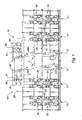
- the web-fed rotary printing press shown by way of example has a left and a right section, each having at least two printing towers 01.
- the printing towers 01 have printing units 02, which z. B. at least three times wide, ie for the printing of six axially juxtaposed newspaper pages executed.
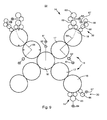
- the printing units 02 are designed as satellite printing units 02.
- the advantageous embodiment of the printing units 02 as nine-cylinder satellite printing units 02 ensures a very good Passerhaltmaschine or a low fan-out.
- the printing units 02 can also be used as ten-cylinder satellite printing units 02 or, if appropriate, also as printing units that can be operated in rubber-against-rubber printing, such as, for. B. be executed a plurality of bridge printing units or a H-printing unit 02.
- the printing units 02 are webs 03 supplied by rollers, not shown, in particular using reel changers.
- a superstructure 04 Downstream of the printing towers 01 or printing units 02 continuous web 03, here above the printing towers 01, a superstructure 04 is provided for each section, in which the web 03 or webs 03 cut on longitudinal cutting devices 06, sub-webs by means of turning devices 07 possibly offset and / or crashed, by means of in Fig. 1 only indicated register devices 08 are aligned in the longitudinal register to each other and can be performed one above the other.
- the superstructure 04 has at least one so-called harp 09 with a number of superimposed webs 03 or part webs 03a; 03b; 03c leading harp or caster rollers.
- the harp 09 determines the funnel inlet of the superimposed tracks 03. About this harp 09, the tracks 03 undergo a change in direction and are subsequently summarized either as a strand or as multiple strands and fed to at least one folding structure 11.
- two Falz admittedten 11 are arranged between the sections, which z. B. each have arranged on two different superposed planes folding former.
- the printing machine can also only a common, between the sections arranged folding structure 11, or only have a section and an associated folding structure 11.
- the respective folding structure 11 may be performed with only one level of formers.
- Each folder assembly 11 are associated with one or more folders 12.
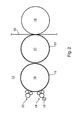
- the printing unit 02 has several, in the example four, printing units 13, by means of which ink can be applied to the web 03 by an inking unit 14 via at least one cylinder 16 designed as a forme cylinder 16 ( Fig. 2 ).
- the printing unit 13 is designed as offset printing unit 13 for the wet offset and has in addition to the inking unit 14, a dampening unit 20 and another cylinder 17 designed as a transfer cylinder 17.
- the transfer cylinder 17 forms a pressure point with an abutment-forming impression cylinder 18.
- the printing cylinder 18 is designed as a satellite cylinder 18, which forms further pressure points with further transfer cylinders 17 further printing units 13 in the print-on position.
- the printing cylinder 18 could also be designed as a transfer cylinder 18 in the formation of the printing units as a double printing unit in the rubber counter-rubber pressure.
- the same parts are given the same reference numerals, as far as they are not necessary for differentiation. However, a difference in the spatial position may exist and, in the case of the assignment of the same reference numbers, is generally disregarded.
- the inking unit 14 has, in an advantageous embodiment, an ink fountain 15 extending over six print pages. In another embodiment, three each color about two pages wide ink boxes 15 are arranged side by side in the axial direction.
- the dampening unit 20 is designed in an advantageous embodiment as allocate to the dampening 20.
- the form cylinder 16 has in a first embodiment z. B. a circumference between 850 and 1,000 mm, in particular from 900 to 940 mm.
- the scope is z. B. for recording two stationary printed pages, z.
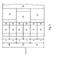
- the printing plates 19 are mounted in the circumferential direction on the forme cylinder 16 and in the in Fig. 3 shown embodiment as each in the axial direction with a printed side stocked single pressure plate individually interchangeable.
- the length L16 of the usable bale of the forme cylinder 16 is in the first embodiment z. B. 1,850 to 2,400 mm, in particular 1,900 to 2,300 mm and is in the axial direction for receiving z. B. at least six juxtaposed standing printed pages, especially newspaper pages in broadsheet format, measured (see Fig. 3 Sections A to F). Among other things, it depends on the nature of the product to be produced, whether in each case only one pressure side or several pressure sides in the axial direction are arranged side by side on a printing plate 19. In an advantageous broader variant of the first embodiment, the length L16 of the usable bale is between 2,000 and 2,400 mm.
- the forme cylinder 16 has z. B. a circumference between 980 and 1300 mm, in particular from 1000 to 1200 mm.
- the length L16 of the usable bale is in this case z. B. 1,950 to 2,400 mm, in particular 2,000 to 2,400 mm.
- the occupancy corresponds to the o. G. Execution.
- the transfer cylinder 17 also has a circumference z in the first embodiment. B. between 850 and 1,000 mm, in particular from 900 to 940 mm.
- the length L17 of the usable bale of the transfer cylinder 17 is in the first embodiment z. B. 1,850 to 2,400 mm, in particular 1,900 to 2,300 mm and is in the longitudinal direction of each other z. B. with three elevators 21, z. B. blankets 21, occupied (sections AB to EF). They extend in the circumferential direction substantially to the full extent.
- the length L17 of the usable bale is also between 2,000 and 2,400 mm.
- the transfer cylinder has 17 z. B. a circumference between 980 and 1300 mm, in particular from 1000 to 1200 mm.
- the length L17 of the usable bale is in this case z. B. 1,950 to 2,400 mm, in particular 2,000 to 2,400 mm.
- the occupancy of elevators 21 corresponds to the first embodiment.
- Diameter of bales of cylinders 16; 17 are in the first o. G. Execution z. B. from 270 to 320 mm, in particular from about 285 to 300 mm. In the second o. G. Execution is the diameter of bales of the cylinder 16; 17 z. B. from about 310 to 410 mm, in particular from 320 to about 380 mm. A ratio of a length of the usable bale of the cylinders 16; 17 to the diameter should be 5.8 to 8.8, z. B. at 6.3 to 8.0, in a wide version, especially at 6.5 to 8.0.
- length L16; L17 of the usable bale here is to be understood that width or length of the bale, which for receiving elevators 19; 21 is suitable. This corresponds approximately to a maximum possible web width of a web to be printed 03. Based on an entire length of the bale of the cylinder 16; 17 would be L16 to this length; L17 of the usable bale nor the width of any existing Schmitzringen, possibly existing grooves and / or possibly existing lateral surface areas added, which z. B. to operate clamping and / or clamping devices must be accessible.
- the satellite cylinder 18 also substantially the dimensions and ratios of at least the associated transfer cylinder 17 substantially.
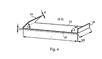
- Elevators 19; 21 are like in Fig. 4 shown schematically z. B. as flexible plates executed, wherein the designed as a blanket 21 elevator 21 as a so-called.
- a plate-shaped printing plate 19 and a support plate 23 for a rubber blanket is usually made of a flexible, but otherwise dimensionally stable material, for. B. of an aluminum alloy, and has two opposite, in or on the cylinder 16; 17 to be fastened ends 24; 26 with a material thickness MS of z. B.
- a leading end 24 is, for example, at an acute angle ⁇ of 40 ° to 50 °, in particular 45 °, and a nachaufendes end 26 at an angle ⁇ of 80 ° to 100 °, in particular 90 °, folded.
- the folded ends 24; 26 of the elevators 19; 21 each in a on the circumference of the respective cylinder 16; 17 longitudinally axially parallel, slot-shaped opening can be inserted, wherein the ends 24; 26, for example, be held by their shape, friction or deformation. However, they can also be fixed by means of spring force, by pressure medium or an effective during operation centrifugal force operable means.
- the slot-shaped openings for axially juxtaposed pressure plates 19 on the forme cylinder 16 are in an advantageous embodiment in each case in alignment, z. B. as a continuous slot-shaped opening (as described below), arranged, while the openings for the juxtaposed on the transfer cylinder 17 blankets 21 are not continuous, but offset from one another in the circumferential direction by 180 °.
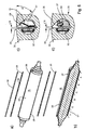
- Fig. 5a and b In a perspective view of an example of an advantageous embodiment of the forme cylinder 16.
- two channels 27 are provided, both channels 27 throughout in the axial direction of the cylinder 16 at least over the entire length of the six sections A to F in the bale extend ( Fig. 5b ). They are in the circumferential direction of the cylinder 16 z. B. offset by 180 ° to each other.
- the arranged below a lateral surface 30 in the interior of the cylinder 16, z. B. as circular holes running channels 27 have, at least over the length of the six sections A to F a narrow, slot-shaped opening 28 to the lateral surface 30 of the cylinder 16 on ( Fig. 5a ).
- a slot width s16 of the opening 28 on the forme cylinder 16 in the circumferential direction is less than 5 mm and is preferably in the range of 1 mm to 3 mm (FIG. Fig. 5c ).
- the folded ends 24; 26 of the printing plate 19 are now each in one of the circumferentially axially parallel openings 28 can be inserted and are, at least the trailing end 26, fixed by a arranged in the channel 27 holding device 29, 31.
- the holding device 29, 31 here has at least one clamping piece 29 and a spring element 31 ( Fig. 5c ).
- the not shown right angle beveled trailing suspension legs 26 (see Fig. 4 ) preferably abuts against a wall of the opening 28 that is essentially completely shaped for bending and is pressed there by the clamping piece 29 by a force exerted by the spring element 31 on the clamping piece 29.
- the acute angle beveled leading suspension leg 24, not shown, preferably abuts a wall of the opening 28 that is substantially complementary to the fold and that forms a hooked edge or nose with the jacket surface 30 at an acute angle ⁇ 'of 40 ° to 50 °, in particular 45 °.
- an adjusting means 32 is provided in the channel 27, which at counteracts its operation of the force exerted by the spring element 31 on the clamping piece 29 force and the clamping piece 29 pivots away from the wall or the end 26.
- each channel 27 not only a clamping piece 29, but over the length of the sections A to F axially adjacent a plurality of clamping pieces 29 in the manner of segments each having at least one spring element 31 is arranged (in Fig. 5a from the cylinder 16 "pulled out” shown).
- each section A to F more, z. B. six, such clamping pieces 29 according to Fig. 5c arranged, wherein in the middle between the clamping elements 29 of each section A to F, here between the third and the fourth clamping element 29 of each section A to F, in each case a registration stone 35 exhibiting Passerelement 33 (FIGS. Fig. 5d ) is arranged.
- index block 35 can in unillustrated development also via axially guided in a vacant cavity of the channel 27 and the fitting element 33 actuator z.
- a motor-driven threaded spindle be axially movable.
- the actuating means 32 is designed in the illustrated embodiment such that when actuated the holding device (s) 29, 31, ie all the clamping pieces 29, are simultaneously closed or loosened over the length of the sections A to F.
- the adjusting means 32 is as in Fig. 5a from the cylinder 16 "pulled out” represented as at least over the length of the sections A to F reaching, axially extending in the channel 27 and actuated by pressure reversibly deformable hollow body 32, z. B. as a hose 32, executed.
- This hose 32 is according to Fig. 5c with the clamping pieces 29 acting together in the channel 27 arranged so that it counteracts the self-locking the holding device closing spring elements 31 upon actuation. Through the areas of passer elements 33 it is passed ( Fig. 5d ).
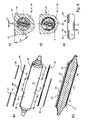
- Fig. 6a and b shows in a perspective view an example of an advantageous embodiment of the transfer cylinder 17.
- the cylinder 17 has two channels 36; 37 provided, wherein both channels 36; 37 continuously in the axial direction of the cylinder 17 at least over the entire length of the six sections A to F and three sections AB; CD; EF, in bale stretch ( Fig. 6b ). They are in the circumferential direction of the cylinder 17 z. B. offset by 180 ° to each other.
- Two of the three openings 38; 39 are in communication with the same channel 36 and are aligned with each other in the axial direction, but spaced from each other on the lateral surface 40.
- Axial between the two openings 38; 39 is a the shape of the remaining lateral surface 40 füretzender, interpretedr undisturbed section U without opening.
- the two aligned, z. B. with the same channel 36 communicating openings 38; 39 are preferably the face-side openings 38; 39, wherein the third opening 41 extends axially at least over the central gate CD and offset by 180 ° to the other openings 38; 39 is arranged.
- a slot width s17 of the uncovered opening 38; 39; 41 on the transfer cylinder 17 in the circumferential direction is less than 5 mm in each case and is preferably in the range of 1 mm to 3 mm ( Fig. 6c ).
- radially extending holes 42 may be provided, which is closed or closed in the operating state of the cylinder 17 by means of a plug, not shown ( Fig.
- the plug has an outer surface which continues the otherwise cylindrical contour of the cylinder 17 in the mounted state in the region of the bore 42.
- the openings 38 In the circumferential direction of the cylinder 17 in a section perpendicular to the axis of rotation in an advantageous embodiment only one of the openings 38; 39; 41 or one the shortened by the plug opening 38; 39; 41 arranged one behind the other. In this section, the openings 38 thus overlap; 39; 41 or shortened by the plug opening 38; 39; 41 not.
- the folded ends 24; 26 of the blanket 21 are now each in one of the circumferentially axially parallel openings 38; 39; 41 inserted and are, at least the trailing end 26, respectively by at least one in the channel 36; 37 arranged holding device 43, 44 fixable.
- the two ends 24; 26 of the same blanket 21 through the same opening 38; 39; 41 in the same channel 36; 37 led.
- the holding device 43, 44 has here in each case at least one clamping piece 43 and a spring element 44 (FIG. Fig. 6c ).
- the not shown right angle beveled trailing suspension legs 26 (see Fig. 4 ) preferably arrives at a wall of the opening 38 that is substantially complementary to the fold; 39; 41 to the system and is pressed there by the clamping piece 43 by a force exerted by the spring element 44 on the clamping piece 43 force.
- the acute angle beveled leading suspension leg 24, not shown, (see Fig.
- each channel 36; 37 not just a clamping piece 43, but are about the length of sections AB; CD; EF axially next to each other a plurality of clamping pieces 43 as individual segments, each with at least one spring element 44 arranged (in Fig. 6a from the cylinder 17 "pulled out” shown).
- sections AB; CD; EF of the respective channel 36; 37 which have no opening to the lateral surface 40, instead of the holding device 43, 44 or the holding devices 43, 44 at least one filling element 49 (FIG. Fig.
- this filling elements 49 as individual segments in the relevant, no opening having section AB; CD; EF of the channel 36; 37 arranged. Centered between the retainers 43, 44 of each section AB; CD; EF, ie in the region between the sections A and B or E and F, here between the fifth and sixth clamping element 43, can also each have a filling element 49 (FIG. Fig. 6d ) can be arranged.
- the filling element 49 has substantially the cross section of the channel 36; 37 imitated cross-section and at least one axially continuous opening 51, through which a means for the actuating means 46; 47; 48 is feasible.
- the adjusting means 46; 47; 48 is designed in the illustrated embodiment such that when actuated the holding means 43, 44 of a section AB; CD; EF, ie all clamping pieces 43 of a section AB; CD; EF, simultaneously closed or solved.
- the adjusting means 46; 47; 48 is in Fig. 6a from the cylinder 17 "pulled out" shown.
- an adjusting means 46 extends at the front side; 47 over at least the corresponding length of the section AB; EF.
- the middle opening 41 associated adjusting means 48 also extends over at least the corresponding length of the associated portion CD.
- the adjusting means 46; 47; 48 are each as axially in the channel 36; 37 extending and actuated by pressure medium reversibly deformable hollow body 46; 47; 48, z. B. as a hose 46; 47; 48, executed.
- This hose 46; 47; 48 is according to Fig. 6c with the clamping pieces 43 so cooperating in the channel 36; 37 arranged to counteract the self-locking the holding device 43, 44 closing spring elements 44 when actuated.
- channels 36; 37 these can also not be carried out continuously over the entire length.
- the channels 36; 37 in the area of each section AB; CD; EF one channel 36 each; 37, possibly provided with a corresponding holding device, wherein the channel 37 of the central elevator 21 is offset from the two outer by 180 °. This is in 6E indicated only schematically.
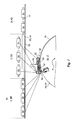
- 17 advantageous embodiment is at least two cylinders 16; 17, in particular two forme cylinders 16, at least one of the printing towers 01 each have a device 52 for pressing an elevator 19; 21 to a cylinder 16; 17, in particular a printing plate 19 to the forme cylinder 16, (hereinafter Andrückvorraum 52) assigned.
- This is z. B. advantageous if in two corresponding printing units 13 a faster, z. B. flying plate change to be made.
- a corresponding pressing device 52 has one or more pressing elements 53; 54, z. B.
- the pressing device 52 extends along the cylinder 16; 17 at least in the entire range of sections A to F, ie in the effective for printing area of the bale.
- the pressing device 52 has sections A to F (in the case of six elevators 19 arranged next to each other) or section AB; CD; EF (in three juxtaposed elevators 21) at least a first pressure element 53, z. B. rolling element 53, on.
- it has sections A to F and section AB respectively; CD; EF in a circumferential direction of the cylinder 16; 17 spaced from this first rolling element 53 second pressing element 54, z. B. rolling element 54, on.
- Fig. 7 in the case of the forme cylinder 16, only central portions B, C and D and the rolling elements 53 associated with these portions B, C and D are; 54 is shown.
- Each section A to F or AB to EF is a first rolling element 53 or a group of axially adjacent to each other first rolling elements 53 and z.
- B. a second rolling element 54 or a group of axially juxtaposed second rolling elements 54 are arranged.
- a first rolling element 53 and a group of three second rolling elements 54 are shown per section A to F or AB to EF.
- Advantageous in terms of the risk of possible tilting and possibly faulty axial alignment is the arrangement of groups of at least two each independently movable rolling elements 53; 54.
- a single rolling element 53; 54 for a section A to F and AB to EF for example, as in the longitudinal direction almost over the length of the section A to F and AB to EF extending roller 53; 54 executed, a rolling element 53; 54 of a group, however, z. B. only as the highest a fraction of the length of the section A to F and AB to EF having roller 53; 54th
- the axially juxtaposed rolling elements 53; 54 and, if provided, the circumferentially successively arranged rolling elements 53; 54 are in principle independently movable on, for example, a traverse 56 (or more traverses 56) arranged.
- the single first rolling element 53 or the group of first rolling elements 53 of each section A to F or AB to EF and, if provided, the single second rolling element 54 or the group of second rolling elements 54 of each section A to F and AB to EF are independent of each other by their own adjusting means 57; 58 actuated.
- These adjusting means 57; 58 are, for example, as reactable with pressure medium reversibly deformable hollow body 57; 58, in particular as a hose 57; 58 executed. But it can also be provided differently type of electrically or magnetically actuable actuating means.
- the first or first rolling elements 53 assigned to this section A to F or AB to EF and, if provided, the second rolling elements 54 assigned to this section A to F or AB to EF are coupled to the cylinder 16; 17 or to be wound up, already hinged elevator 19; 21 hired.
- the first and / or second rolling elements 53, which concern this section A to F or AB to EF, will also be arranged; 54 to the respective elevator 19; 21 hired.
- first and second rolling elements 53; 54 presses when rolling the cylinder 16; 17 with the rolling elements 53; 54, the second rolling element 54, the trailing bent end 26 of the elevator 19; 21 in rolling into the opening 28; 38; 39; 41.
- first rolling elements 53 are provided, it is pushed in through them.
- the rolling elements 53 remain; 54 stationary, while the cylinder 16; 17 is rotated in a direction of production P.
- Does the pressing device 52 each have first and second rolling elements 53; 54, the elevators to be left 19; 21 advantageously held down by at least the second rolling elements 54.
- first at least the second rolling element 54 is turned off, so that the end 26 of the channel 27; 36; 37 can escape, and the first rolling element 53 employed, so that the already partially dissolved elevator 19; 21 still on the cylinder 16; 17 is managed and held.
- the cylinder 16; 17, preferably counter to the direction of production P are rotated until the leading end 24 of the channel 27; 36; 37 removed, and the elevator 19; 21 can be removed.
- the elevator 19; 21 no remaining elevators 19; 21, so the rolling elements 53; 54 of the not to be solved elevator 19; 21 concerned sections A to F and AB to EF during the procedure, in principle, any operating positions, preferably off, occupy.
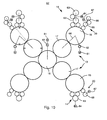
- the cylinder 16; 17; 18 of the printing unit 02 driven so that the printing units 13 of the printing unit 02 are rotatably driven in each case at least by one of the other printing units 13 mechanically independent drive motor 61.
- the satellite cylinder or cylinders 18 are likewise rotationally drivable by a drive motor 61, mechanically independently of the associated printing units 13.
- the drive motors 61 are preferably as with respect to their angular position controlled electric motors 61, z. B. as asynchronous motors, synchronous motors or DC motors.
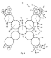
- FIGS. 8 to 10 have only the components of the right half of the figure corresponding reference numerals, since the left side corresponds to the right mirror image.
- Fig. 8 all nine cylinders have 16; 17; 18 each have their own drive motor 61, which in each case z. B. via a gear 62 on the cylinder 16; 17; 18 drives.
- the inking unit 14 shown above has, in addition to other, unspecified rollers on two distribution cylinders 63 which are rotationally driven together by means of a separate drive motor 64.
- the two distribution cylinders 63 are axially movable and driven by an unillustrated drive means for generating an axial stroke.
- the inking unit 14 shown below has only one distribution cylinder 63.
- the dampening unit 20 shown above has, in addition to other, not designated rolls on two distribution cylinders 66 which are rotationally driven together by means of a separate drive motor 67.
- the two distribution cylinders 66 are axially movable and driven by an unillustrated drive means for generating an axial stroke.
- the dampening unit 20 shown below has only one distribution cylinder 66.
- the two cylinders 16; 17 each printing unit 13 in the execution to Fig. 9 each driven by a common drive motor 61 on the transfer cylinder 17.
- the drive can be axial, z. B. via a gear 62, done or via a on a drive wheel of the transfer cylinder 17 driving pinion. From the drive wheel of the transfer cylinder 17 can then be driven off to a drive wheel of the forme cylinder 16.
- the drive connection 68 (shown as a connecting line) can be made as a gear connection or via belt and is executed encapsulated in development.
- For the drive of the color and possibly dampening unit 14; 20 via their own drive motors 64; 67 or a cylinder 16; 17; 18 is basically that too Fig. 8 applied.
- the drive motor 61 drives via a pinion 71 on a rotationally rigidly connected to the forme cylinder 16 drive wheel 72, which in turn drives on a torsionally rigidly connected to the transfer cylinder 17 drive wheel 73.
- the drive wheel 73 is either widened or it is a second drive 74 connected to the transfer cylinder 17.
- the widened or additional drive wheel 73; 74 drives via a rotatably mounted on a pin 76 of the forme cylinder 16 drive wheel 77 on a drive wheel 78 of the inking and / or dampening unit 14; 20.
- the drive wheels 72; 73; 74; 77; 78 are preferably designed as gears.
- the forme cylinder 16 is adapted to be axially displaceable axially by, for example, ⁇ ⁇ L
- at least the pinion 71 and the drive wheels 72 to 74 are straight meshed executed.
- the drive motor 61 and the gear 62 of the pinion 71 and the drive wheel 72 may additionally be a dashed lines indicated, encapsulated auxiliary gear 62 'may be arranged.
- the drive to the forme cylinder 16 can also take place axially on the journal 76, wherein, if appropriate, an axial movement of the forme cylinder 16 takes place via an unillustrated, axial relative movement between the forme cylinder 16 and the drive motor 61 receiving coupling.
- the satellite cylinder 18 is also driven in this illustration via a pinion 71 on an associated drive wheel 79, in particular gear 79.
- Each driven by an independent drive motor 61 drive train is in an advantageous embodiment, at least for themselves, possibly encapsulated in even smaller units (stiched in Fig. 11 shown).
- the described embodiments of the printing unit 02 and the printing units 13 and their cylinders 16; 17; 18 and the drive allows a low-vibration, accurate printing high quality with a low on the achievable product strength technical and spatial complexity.
- Fig. 12 shows in a perspective oblique view, a first embodiment of at least a portion of the superstructure 04.
- the partial web 03b shown as turned from the center to the outside part web 03b.
- a second of the partial webs 03a; 03c could also be turned into another flight, for example, by means of a second such turning device 07.
- a second turning device can, for. B. above or below the first turning device 07 lie.
- the turning device 07 has, as a guide element 82, as usual, two parallel or crossed turning bars 82, which with the transport direction of the incoming part web 03a; 03b; 03c form an angle of about 45 ° or 135 °, and by means of which an incoming web 03a; 03b; 03c is laterally displaceable and / or can be staggered.
- the turning bars 82 advantageously have a length L82, the projection of which on the transverse extent of the incoming partial web 03a; 03b; 03c insignificantly larger, z. B. 0% to 20% larger than the width of the incoming partial web 03a; 03b; 03c, ie the length L82 is approximately 1.4 to 1.7 times the partial web width.
- At least the length L82 is selected such that its projection is less than or equal to twice the width of a two-side width partial web 03a; 03b; 03c, ie the length L82 is at most 2.8 times the partial web width.
- the turning bars 82 are each mounted individually on carriers 83, which transverse to the direction of the incoming partial web 03a; 03b; 03c can be moved on at least one guide 84.
- the now “short” turning bars 82 can now bring depending on the requirements of the desired web guide in the required position. Under certain circumstances, both turning bars 82 may be mounted on such a carrier 83.
- the register device 08 has, as a guide element 86, at least one roller 86 which can be moved parallel to the running direction.
- the roller 86 or a plurality of rollers 86 of the register device 08 advantageously have a length L86 which is insignificantly larger, for. B. 0% to 20% greater than the width of the incoming partial web 03a; 03b; 03c is.
- At least the length L86 is less than or equal to twice the width of a two-side-width partial web 03a; 03b; 03c.
- the register device 08 is transverse to the direction of the incoming partial web 03a; 03b; 03c stored on at least one guide 87 movable. The now narrow register device 08 or its short rollers 86 can now be brought to the required position from the desired web guide as required.
- Harp 09 ( Fig. 1 ) is supplied.
- For straight from running webs 03 or partial webs 03a; 03b; 03c is in the superstructure 04 upstream of the harp roller 89, for example, over the full web width b03 reaching, in the transport direction spatially variable register roller 91 and a guide roller 92 is arranged.
- the "short" harp roller 88 is realized as a section 88 of a harp roller 89 which is divided in this embodiment but extends over a total of six printing pages wide web 03.
- the sections 88 are rotatably supported independently of each other here.
- FIG. 93 may also, as in FIG Fig. 13 shown, as individually arranged on a frame harp roller 93 executed. This can then either fixed to the frame, or on a support 94 on a guide 96 transversely to the direction of the incoming part of the web 03a; 03b; 03c be arranged variable in location.
- the required register device 08 at least one of the course of the partial web 03a; 03b; 03c determining guide elements, such. B. the turning device 07 or a turning bar 82 or the harp 09 or a "short" harp roller 93, are assigned.
- Fig. 13 is the "short" register device 08 z. B. the "short” harp roller 93 assigned and along with this on the guide 96 transversely to the direction of incoming partial web 03b; 03c adjustable.
- Fig. 14 is the "short" register device 08 z. B. associated with one of the "short” turning bars 82 and together with this on the guide 84 transversely to the direction of the incoming part web 03b locally variable.
- this arrangement is shown here for crossed turning bars 82, but on parallel turning bars 82 from Fig. 11 apply.
- the crossed or mutually orthogonal turning bars 82 is at least one (here two) guide roller 97 with perpendicular to the axis of rotation of the roller 81 extending axis of rotation.
- the guides 84; 96 ( FIGS. 13 and 14 ) of the aforementioned embodiments can be realized in many different ways.
- the guides 84; 96 be designed as spindles with at least sections threaded, which rotatably mounted on both sides and z. B. are rotatably driven by a drive, not shown.
- the carriers 83; 94 can in the manner of sliding blocks in rigid guides 84; 96, z. B. on profiles, be performed.
- a drive of the carrier 83; 94 also via a drivable spindle or otherwise done.
- transversely adjustable turning bar 82 By means of the transversely adjustable turning bar 82 are variable transfers or offset of partial webs 03a; 03b; 03c over one or two partial web widths (or even multiples of a half partial web width) away possible.
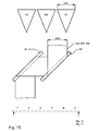
- the printed partial webs 03a; 03b; 03c in the flight of one of several, here three, transverse to the direction of juxtaposition of the former 101; 102; 103 ( Fig. 15 ) of the folder assembly 11.
- the transfer takes place, for example, to the requirement to correspond to different strengths of individual strands or ultimately intermediate or end products, at the same time an effective printing should be done with the fullest possible web widths.
- the superstructure 04 advantageously has at least (n * (m / 2 - 1)) turning devices 07.
- n * (m / 2 - 1) the number of turning devices 07 per section of advantage.
- a printing press with z. B. two sections of three printing towers 01 and a total of six provided for the two-sided four-color four printing pages wide webs 03; 03 '; 03 "are arranged at least three turning devices 07 per section.
- a printing machine with z. B two sections of two printing towers 01 and a total of four provided for the two-sided four-color printing six printed pages wide webs 03; 03 '; For example, four turning devices 07 per section are arranged in this printing press In this printing press with two sections or a total of four printing towers 01 (four webs 03, 03 '), a product with a total thickness of 96 pages can be produced in the collective operation.
- a partial path 03a; 03b; 03c is offset by an odd multiple of half the partial web width b03a and / or funnel width (ie by a factor of 0.5, 1.5, 2.5) ( Fig. 15 ).
- This can be done by means of long over the entire width of the printing press or the width b03 of the entire web 03 reaching turning bars (not shown), but also advantageously by means of the above-described portable "short" turning bars 82.
- the Turning bars 82 are then, for example, as in Fig.
- the partial track 03a offset by an odd multiple of half the funnel width b101 or partial track width b03a; 03b; 03c thus runs "between" the formers 101; 102; 103.
- the part track 03a offset by an odd multiple of half the part track width b03a; 03b; 03c is in front of the former 101; 102; 103 in a between the two aligned folding hoppers 101; 102; 103 longitudinal flight cut and runs on the folding structure 11 and the harp 09, ie undivided and / or split harp roller 89 and / or "short" harp roller 93 to ( Fig. 16 ).
- Fig. 16 is a schematic section of the Fig. 15 with exemplary differently executed harp rollers 89; 93, wherein, for example, the partial web 03c has been offset from its original position (shown unfilled) by one and a half partial web widths b03a. It can, for example, if they are provided with a further longitudinal cutting device 104 in front of the formers 101; 102; 103 is cut (then in each case one printed page or newspaper page wide), each half in each case with the partial webs 03a and 03b on each of a former 101; 102 are led. The two (intermediate) products then have z. B.
- a total product has z. B. 48 pages. If this printing machine is operated in double production, ie the forme cylinder 16 is in the circumferential direction with two printing plates 19 same printed pages A1, A1; to F1, (or A1 ', A1' to F1 ', F1') occupied and in the folder 12 is not collecting, so are on the strands 109, 111 and 112, two identical successive issues of the above page numbers generated. It produces a total product with only 24 pages, but with double output.
- the harp rollers 89; 93 in particular if they are executed undivided over the full length, can be rotationally driven in a development on its own, not shown drive motors. These are then z. B. with respect to their speed, u. U. also their location, run controllable and are to take over current setpoints with the machine control or an electronic master axis in combination.
- the folding structure 11 has at least two stacking rollers 101, 106 arranged one above the other; 102, 107; 103, 108, whose planes of symmetry S in each case in a common escape of the printing press straight through part of web 03a; 03b; 03c lie.
- the planes of symmetry S of the two stacked formers 101, 106 fall; 102, 107; 103, 108 substantially together with a median plane M of a two printed pages wide, straight running, only deflected in the vertical direction partial web 3a; 3b; 3c (3a ', 3b', 3c ', 3a ", 3b", 3c ", 3a'", 3b '", 3c'', etc.)
- the partial webs 3a, 3b, 3c, etc. are in Fig. 17 from one below (to Fig. 18 ) explained reason partially drawn and shown in dotted line to another part.
- the three formers 101; 102; 103 and 106, respectively; 107; 108 of a group are transverse to the direction of the partial webs 03a; 03b; 03c offset from one another next to each other and arranged in an advantageous embodiment substantially at a same height. However, they may also be vertically offset from each other and / or have different vertical dimensions, but then z. B. in the horizontal plane at least partially overlap.
- the folding structure 11 Seen in the web running direction, the folding structure 11 at least in front of one of the superimposed groups of formers 101; 102; 103 and 106, respectively; 107; 108 the funnel inlet of the webs 03; 03 '; or partial webs 03a; 03b; 03c defining harp 09, ie a group of several parallel, offset in the radial direction casserole or Harfenwalzen 89; 93, over which different tracks 03; 03 'or partial webs 03a; 03b; 03c; or 03a '; 03b '; 03c 'etc. are transferred from the superstructure 04 in the folding structure 11.
- the harp rollers 89; 93 of a harp 09 are mutually vertically and / or horizontally offset and preferably stored as a unit in a common frame.
- a harp 09 may be provided for each of the vertically offset groups of formers 101; 102; 103 and 106, respectively; 107; 108 such a harp 09 may be provided.
- the harp 09 advantageously comprises at least (n * m / 2) harp rollers 88; 89; 93, whose axes of rotation z. B. are substantially in a common plane, and which are preferably stored in a common frame.
- two tracks 03; 03 '(or two printing towers 01) are at least six harp rollers 88; 89; 93 per harp 09 of advantage.
- harp rollers 88, 89, 93 are arranged per harp 09.
- a product with a total thickness of 72 pages can then be produced in the collecting operation.
- a printing machine with z. B two sections of two printing towers 01 and a total of four provided for the two-sided four-color printing six printed pages wide webs 03; 03 '; 03 ", at least six harp rollers 88, 89, 93 are arranged per harp 09 of a section
- These six harp rollers 88, 89, 93 per section, here twelve, can be arranged in two structurally separate harps 09, eg over a common folding structure 11 or two folding structures 11, but also in a structurally common harp 09 eg in two alignments be
- this printing press with two sections or a total of four printing towers 01 (four tracks 03, 03 ') is then in the collecting a product with a Total thickness of 96 pages can be generated.
- a printing press with z. B. two sections of two printing towers 01 and a total of four provided for the two-sided four-color printing six printed pages wide webs 03; 03 '; 03 ", at least six harp rollers 88, 89, 93 are arranged per harp 09 of a section
- These six harp rollers 88, 89, 93 per section, here twelve, can be arranged in two structurally separate harps 09, eg over a common folding structure 11 or two folding structures 11, but also in a structurally common harp 09 eg in two alignments be
- this printing press with two sections or a total of four printing towers 01 (four tracks 03, 03 ') is then in the collecting a product with a Total thickness of 96 pages can be generated.
- the number of harp rollers required is 89; 93 according to the configuration of the two sections. If the folding structure 11 is arranged between these two sections, then either all the harp rollers 89; 93 in an escape or to save height the harp rollers 89; 93 of each section each arranged in alignment and the alignment with each other in the radial direction offset horizontally.
- the harp rollers 89; 93 of the two escapes are here z. B. again arranged in a common frame.
- Fig. 18 is at least one of the partial webs 03a; 03b, 03c, etc., which are in front of the upper former 101; 102; 103 arranged common harp 09 passes through, on the lower former 106; 107; 108 feasible or guided.
- the partial webs 03a; 03b; 03c etc. are more or less of the partial webs 03a; 03b; 03c etc. on the upper and lower former 101; 102; 103 and 106, respectively; 107; 108 to convict.
- different strands 109; 111; 112; 113; 114; 116 on the respective lower and upper former 101; 102; 103 and 106, respectively; 107; 108 will be given.
- Fig. 17 the dashed in Fig. 17 partial webs shown as strand 113; 114; 116 on the respective lower former 106; 107; 108, and the solid on the respective top Former 101; 102; 103 led.
- This is, depending on where the "separation" in superimposed partial webs 03a; 03b; 03c etc. from the common harp 09 is a flexible production of different strong intermediates (booklets, books) or end products possible with reduced effort.
- Fig. 18 is a second escape from harp rollers 89; 93 shown by dashed lines, by means of which, as described above, for example, partial webs 03a; 03b; 03c etc. can be recorded from another section.
- the aforementioned folding structure 11 with only one harp 09 for two superposed formers 101; 102; 103; 106; 107; 108 is also suitable for other printing machines with different cylinder widths and cylinder circumferences. Such, from two stacked formers 101; 102; 103; 106; 107; 108 and a common harp 09 existing Falzoberbau 11 may also be arranged on a third former with its own harp 09.
- the described folding structure 11 with a plurality of vertically offset formers 101; 102; 103; 106; 107; 108 assigned harp 09 is also on three superposed formers 101; 102; 103; 106; 107; 108 well applicable.
- Outside pages, for example, of an outer book can thus be assigned to a specific web guide and / or a specific printing tower / printing unit.
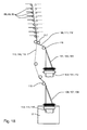
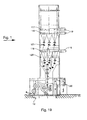
- the formers 101; 102; 103; 106; 107; 108 in each case upstream Weg 117 and funnel inlet rollers 118 have in an advantageous embodiment as well as provided in the folding structure 11 draw rollers 121 ( Fig. 19 ) each have their own drive motors 119.
- Fig. 19 is the draw roller 117 for the lower group of the formers 106; 107; 108 not visible.
- the respective drive motor 119 of the draw rollers 121 is in Fig. 19 merely represented by filling of the relevant draw roller 121.
- Each of the formers 101; 102; 103; 106; 107; 108, at least one such driven draw roller 121 is arranged downstream in an advantageous embodiment, which with pressure rollers or a pressure roller on the strand 109; 111; 112; 113; 114; 116 cooperates.
- the folding structure 11 preferably has non-driven guide rollers 122, via which the one printing side wide strands 109; 111; 112; 113; 114; 116 can be performed.
- the folder 12 at least one own, of the printing units 02 mechanically independent drive motor 120.
- the drive motors 119 of the tractor inlet rollers 117; 118; 121 of the folding structure 11 and / or driven tension rollers 81 of the superstructure 04 only have to be controlled in terms of speed (with regard to an angular position)
- the drive motor 120 is designed to be adjustable or regulated with respect to its angular position on the folding apparatus 12 in an advantageous embodiment.
- the mechanically independently driven printing units 02 and the folding apparatus 12 (or their drive motors 61, 120) to specify an angular position with respect to a virtual electronic master axis.
- for. B. determines the angular position of the folder 12 (or its drive motor 120) and based on this, the relative angular position of the printing units 02 and 13 printing units specified for this.
- the z. B. only with respect to their speed controlled drive motors 80; 119 of the driven rollers 81; 117; 118 receive their speed specification, for example, from the machine control.
- the dimensioning of the cylinder 16; 17; 18 and the groups of formers 101; 102; 103; 106; 107; 108 is to be applied to each "lying" printed pages, wherein in the circumferential direction or direction of the web 03; 03 ';03a;03b; 03c is a section A; B; C has two lying print pages, the form cylinder 16 then z. B. has a scope corresponding to four horizontal printed pages in tabloid format.
- the number of printed pages in the longitudinal direction remains per web 03; 03 ';03a;03b; 03c and cylinder 16; 17; 18 or funnel width exist.
Claims (35)
- Machine d'impression rotative à bobines, avec une section gauche et une section droite, comprenant chacune au moins une unité d'impression, réalisée sous forme d'unité d'impression satellites à neuf cylindres (02) avec quatre paires constituée chacune d'un cylindre de transfert (17) et d'un cylindre de forme (16) associé, ainsi qu'un cylindre d'impression (18) coopérant, en position d'impression, avec les cylindres de transfert (17), les cylindres de transfert et de forme (17 ; 16) étant réalisés avec une largeur convenant pour l'impression de chaque fois six pages de journaux disposées axialement les unes à côté des autres, caractérisée en ce que la section gauche et la section droite présentent chacune au moins deux tours d'impression (01), présentant chacune deux unités satellites à neuf cylindres (02) disposées l'une au-dessus de l'autre, réalisées avec une largeur convenant pour l'impression de six pages de journaux disposées axialement les unes à côté des autres, et en ce qu'entre les deux sections sont disposées deux structures de pliage (11), présentant chacune des cônes de pliage (101 ; 102 ; 103 ; 106 ; 107 ; 108) disposés sur deux plans différents, situés l'un au-dessus de l'autre.
- Machine d'impression rotative à bobines selon la revendication 1, caractérisée en ce que, au moins sur le cylindre de transfert, les ouvertures sont situées décalées en alternance en direction périphérique, de manière que, au moins sur une longueur de tronçon, toujours une surface d'enveloppe fermée coopère avec le cylindre satellite.
- Machine d'impression rotative à bobines selon la revendication 1, caractérisée en ce que les cylindres de transfert (17) et les cylindres de forme (16) présentent une circonférence correspondant à au moins deux pages d'impression, en particulier pages de journaux au format broadsheet, verticales, disposées l'une derrière l'autre en direction périphérique.
- Machine d'impression rotative à bobines selon la revendication 1, caractérisée en ce que le cylindre de transfert (17) présente, sur trois tronçons (AB ; CD ; EF) de sa surface d'enveloppe (40), trois habillages (21) disposés les uns à côté des autres en direction axiale.
- Machine d'impression rotative à bobines selon la revendication 1, caractérisée en ce que le cylindre de forme (16) présente, sur six tronçons (A ; B ; C ; D ; E ; F) de sa surface d'enveloppe (30), au moins trois habillages (19) disposés les uns à côté des autres en direction axiale et chaque fois deux habillages (19) disposés les uns à côté des autres en direction périphérique.
- Machine d'impression rotative à bobines selon la revendication 1, caractérisée en ce que le cylindre de forme (16) présente, sur sa surface d'enveloppe (30), six habillages (19) disposés les uns à côté des autres en direction axiale.
- Machine d'impression rotative à bobines selon la revendication 5 ou 6, caractérisée en ce que des extrémités des habillages (19) disposés les uns à côté des autres sont mutuellement alignées en direction axiale.
- Machine d'impression rotative à bobines selon la revendication 4 ou 5, caractérisée en ce que le cylindre (16 ; 17) présente sur sa surface d'enveloppe (30 ; 40) au moins deux ouvertures (28 ; 38 ; 39 ; 41) s'étendant axialement, décalées les unes par rapport aux autres en direction périphérique, pour recevoir des extrémités (24 ; 26) des habillages (19 ; 21).
- Machine d'impression rotative à bobines selon les revendications 5 et 8, caractérisée en ce que deux ouvertures (28), mutuellement décalées à 180° en direction périphérique, s'étendent au moins sur la totalité de la longueur des six tronçons (A à F) sur la surface d'enveloppe (30) du cylindre de forme (16).
- Machine d'impression rotative à bobines selon les revendications 4 et 8, caractérisée en ce que le cylindre de transfert (17) présente, sur sa surface d'enveloppe (40), dans la zone des trois tronçons (AB à EF), en chaque alignement axial des ouvertures (38 ; 39 ; 41), au moins un tronçon (U) prolongeant la forme du reste de la surface d'enveloppe (40).
- Machine d'impression rotative à bobines selon la revendication 1, caractérisée en ce qu'à au moins deux cylindres de forme (16) de l'unité d'impression (02) est chaque fois associé un dispositif de pressage (52), pour presser un habillage (19) sur le cylindre de forme (16).
- Machine d'impression rotative à bobines selon la revendication 1, caractérisée en ce que le cylindre de transfert (17) et le cylindre de forme (16) sont couplés mécaniquement par paire pour l'entraînement et sont entraînés de manière mécaniquement indépendante des cylindres d'impression (18) associés.
- Machine d'impression rotative à bobines selon la revendication 12, caractérisée en ce que la paire, formée du cylindre de forme (16) et du cylindre de transfert, est entraînée au moyen d'un moteur d'entraînement (61) spécifique, et le cylindre d'impression (18) présente un moteur d'entraînement (61) spécifique.
- Machine d'impression rotative à bobines selon la revendication 1, caractérisée en ce que, dans le cas d'une unité d'impression à neuf cylindres, la totalité des quatre paires de cylindres (16 ; 17) présentent chacune un moteur d'entraînement (61) spécifique et le cylindre satellite (18) présente un moteur d'entraînement (61) spécifique.
- Machine d'impression rotative à bobines selon la revendication 1, caractérisée en ce que les cylindres (16 ; 17 ; 18) présentent chacun un moteur d'entraînement (61), mécaniquement indépendant des autres cylindres (16 ; 17 ; 18).
- Machine d'impression rotative à bobines selon l'une des revendications 12 à 15, caractérisée en ce que l'entraînement est effectué à partir du moteur d'entraînement (61), par l'intermédiaire d'une transmission (62), en particulier une transmission à roues dentées (62).
- Machine d'impression rotative à bobines selon la revendication 1, caractérisée en ce que les cylindres de transfert (17) présentent, sur leur surface d'enveloppe 40), chaque fois trois habillages (21), disposés les uns à côté des autres en direction axiale, dont les extrémités (24 ; 26) snt disposées en au moins un canal (36 ; 37) s'étendant axialement, avec une ouverture (28 ; 38 ; 39 ; 41) débouchant à la surface d'enveloppe (30 ; 35), d'une largeur (s17) en direction périphérique inférieure ou égale à 3 mm.
- Machine d'impression rotative à bobines selon la revendication 17, caractérisée en ce que les habillages (21) sont chacun réalisés sous forme d'une couche (22) élastique et/ou compressible, disposée chaque fois sur une plaque support (23).
- Machine d'impression rotative à bobines selon la revendication 17, caractérisée en ce qu'elle présente au moins deux, en particulier trois, tours d'impression, constituant une section et auxquelles sont associées une superstructure (04) commune, ainsi qu'une structure de pliage (11) commune.
- Machine d'impression rotative à bobines selon la revendication 19, caractérisée en ce que la superstructure (04) présente au moins un élément de guidage (82 ; 08 ; 93), susceptible d'être placé au choix transversalement à la direction de défilement de la bande (03) dans le chemin de défilement de trois bandes partielles (03a, 03b ; 03c) disposées les unes à côté des autres.
- Machine d'impression rotative à bobines selon la revendication 19, caractérisée en ce que la structure de pliage (11) présente au moins un groupe de trois cônes de pliage (101 ; 102 ; 103 ; 106 ; 107 ; 108) disposés les uns à côté des autres, transversalement à la direction de défilement de la bande (03).
- Machine d'impression rotative à bobines selon la revendication 1 ou 19, caractérisée en ce que la structure de pliage (11) présente au moins deux cônes de pliage (101 ; 106 ; 102 ; 107 ; 103 ; 108) disposés les uns au-dessus des autres, dont les plans de symétrie (S), s'étendant verticalement, sont alignés entre eux.
- Machine d'impression rotative à bobines selon la revendication 11, caractérisée en ce qu'un canal (27) du cylindre de forme (16) présente des dispositifs de maintien (29, 31) pour fixer des extrémités (24 ; 26) des habillages (19) disposés les uns à côté des autres, les dispositifs de maintien (29, 31) du canal (27) étant susceptibles d'être actionnés par un moyen de manoeuvre (32) commun.
- Machine d'impression rotative à bobines selon la revendication 1, caractérisée en ce qu'elle présente deux sections comprenant chacune deux tours d'impression, et en ce qu'au moins une structure de pliage (11) est disposée entre les deux sections.
- Machine d'impression rotative à bobines selon la revendication 1, caractérisée en ce qu'elle présente deux sections comprenant chacune trois tours d'impression, et en ce qu'au moins une structure de pliage (11) est disposée entre les deux sections.
- Machine d'impression rotative à bobines selon la revendication 24 ou 25, caractérisée en ce que deux structures de pliage (11) sont disposées entre les sections.
- Machine d'impression rotative à bobines selon la revendication 1, caractérisée en ce que, entre les deux sections, sont disposées deux structures de pliage (11), présentant chacune deux groupes, chaque fois disposés sur deux plans différents situés l'un au-dessus de l'autre, de chaque fois trois cônes de pliage (101, 102, 103, 106, 107, 108) disposés en décalage mutuel transversalement à la direction de défilement de bandes partielles (03a ; 03b ; 03c).
- Machine d'impression rotative à bobines selon la revendication 1, caractérisée en ce que la structure de pliage (11) présente, au moins en amont de l'un des groupes de cônes de pliage (101 ; 102 ; 103 ; 106 ; 107 ; 108) disposés les uns au-dessus des autres, un groupe de plusieurs rouleaux de franchissement (89 ; 93) parallèles, mutuellement décalés en direction radiale, sur lesquels différentes bandes (03 ; 03') ou bandes partielles (03a ; 03b ; 03c ; respectivement 03a' ; 03b' ; 03c'), etc., provenant de la superstructure (04), sont transférées dans la structure de pliage (11).
- Machine d'impression rotative à bobines selon la revendication 1, caractérisée en ce qu'un groupe de rouleaux de franchissement (89 ; 93) est prévu pour chacun des groupes, mutuellement décalés verticalement, de cônes de pliage (101 ; 102 ; 103 ; respectivement 106 ; 107 ; 108).
- Machine d'impression rotative à bobines selon la revendication 1, caractérisée en ce qu'un groupe de rouleaux de franchissement (89 ; 93) commun est prévu pour les deux cônes de pliage (101 ; 106 ; 102 ; 107 ; 103 ; 108), disposés l'un au-dessus de l'autre, cependant mutuellement alignés dans leur plan de symétrie.
- Machine d'impression rotative à bobines selon la revendication 1, caractérisée en ce qu'à au moins l'une des deux structures de pliage (11) est associé un groupe de rouleaux de franchissement (89 ; 93) comprenant un certain nombre de rouleaux de franchissement (89 ; 93), par l'intermédiaire desquels des bandes (03 ; 03'), imprimées dans l'une des deux sections, sont susceptibles d'être amenées pour retransformation à des rouleaux de franchissement (89 ; 93) de l'autres des deux sections.
- Machine d'impression rotative à bobines selon la revendication 28, caractérisée en ce que, pour la structure de pliage (11), est prévu un deuxième groupe de rouleaux de franchissement (89 ; 93), au moyen desquels des bandes partielles (03a ; 03b ; 03c, etc.) provenant d'une autre section peuvent être prises.
- Machine d'impression rotative à bobines selon la revendication 1, caractérisée en ce que le cylindre de forme (16) porte sur sa surface d'enveloppe (30) six habillages (19), réalisés sous forme de formes d'impression (19), disposées les unes à côté des autres en direction axiale.
- Machine d'impression rotative à bobines selon la revendication 1, caractérisée en ce qu'un appareil de pliage (12) est associé à chaque structure de pliage (11).
- Machine d'impression rotative à bobines selon la revendication 34, caractérisée en ce que l'appareil de pliage (12) présente un moteur d'entraînement (120) spécifique, mécaniquement indépendant des unités d'impression (02).
Applications Claiming Priority (19)
| Application Number | Priority Date | Filing Date | Title |
|---|---|---|---|
| DE10149068 | 2001-10-05 | ||
| DE10149068 | 2001-10-05 | ||
| DE10149997 | 2001-10-11 | ||
| DE10149997 | 2001-10-11 | ||
| DE10202033 | 2002-01-18 | ||
| DE10202033 | 2002-01-18 | ||
| DE10228970 | 2002-06-26 | ||
| DE10228968 | 2002-06-26 | ||
| DE10228968A DE10228968B3 (de) | 2002-06-26 | 2002-06-26 | Zylinderpaar eines Druckwerks einer Rotationsdruckmaschine |
| DE10228970A DE10228970C1 (de) | 2002-06-26 | 2002-06-26 | Zylinder eines Druckwerks einer Rotationsdruckmaschine |
| PCT/DE2002/002410 WO2003016058A1 (fr) | 2001-08-03 | 2002-07-03 | Elements d'impression pour presse d'imprimerie |
| WOPCT/DE02/02410 | 2002-07-03 | ||
| DE10230316 | 2002-07-05 | ||
| DE10230316 | 2002-07-05 | ||
| DE10235391 | 2002-08-02 | ||
| DE10235391A DE10235391A1 (de) | 2002-08-02 | 2002-08-02 | Vorrichtung zum Führen einer Bahn und Bearbeitungsmaschine mit der Vorrichtung |
| DE10238177 | 2002-08-21 | ||
| DE10238177A DE10238177B3 (de) | 2002-08-21 | 2002-08-21 | Vorrichtung zum Andrücken eines Aufzugs an einen Zylinder einer Druckmaschine mit Hilfe von in Umfangsrichtung des Zylinders voneinander beabstandeten ersten und zweiten Wälzelementen |
| EP02776749A EP1438190B1 (fr) | 2001-10-05 | 2002-09-30 | Unite d'impression et presse rotative a imprimer |
Related Parent Applications (2)
| Application Number | Title | Priority Date | Filing Date |
|---|---|---|---|
| EP02776749A Division EP1438190B1 (fr) | 2001-10-05 | 2002-09-30 | Unite d'impression et presse rotative a imprimer |
| EP02776749.0 Division | 2002-09-30 |
Publications (3)
| Publication Number | Publication Date |
|---|---|
| EP1508441A2 EP1508441A2 (fr) | 2005-02-23 |
| EP1508441A3 EP1508441A3 (fr) | 2005-03-02 |
| EP1508441B1 true EP1508441B1 (fr) | 2011-04-20 |
Family
ID=33515006
Family Applications (6)
| Application Number | Title | Priority Date | Filing Date |
|---|---|---|---|
| EP02776748A Revoked EP1432578B1 (fr) | 2001-10-05 | 2002-09-30 | Presse rotative a imprimer |
| EP04101696A Withdrawn EP1440801A3 (fr) | 2001-10-05 | 2002-09-30 | Machine d'impression rotative à bobines |
| EP04101881A Expired - Lifetime EP1466730B1 (fr) | 2001-10-05 | 2002-09-30 | Machine rotative d'impression à bobines |
| EP04105447A Expired - Lifetime EP1508441B1 (fr) | 2001-10-05 | 2002-09-30 | Machine d'impression rotative et plieuse en entonnoir |
| EP02776749A Expired - Lifetime EP1438190B1 (fr) | 2001-10-05 | 2002-09-30 | Unite d'impression et presse rotative a imprimer |
| EP04101694A Expired - Lifetime EP1449657B1 (fr) | 2001-10-05 | 2002-09-30 | Unité d'impression et presse rotative à imprimer |
Family Applications Before (3)
| Application Number | Title | Priority Date | Filing Date |
|---|---|---|---|
| EP02776748A Revoked EP1432578B1 (fr) | 2001-10-05 | 2002-09-30 | Presse rotative a imprimer |
| EP04101696A Withdrawn EP1440801A3 (fr) | 2001-10-05 | 2002-09-30 | Machine d'impression rotative à bobines |
| EP04101881A Expired - Lifetime EP1466730B1 (fr) | 2001-10-05 | 2002-09-30 | Machine rotative d'impression à bobines |
Family Applications After (2)
| Application Number | Title | Priority Date | Filing Date |
|---|---|---|---|
| EP02776749A Expired - Lifetime EP1438190B1 (fr) | 2001-10-05 | 2002-09-30 | Unite d'impression et presse rotative a imprimer |
| EP04101694A Expired - Lifetime EP1449657B1 (fr) | 2001-10-05 | 2002-09-30 | Unité d'impression et presse rotative à imprimer |
Country Status (9)
| Country | Link |
|---|---|
| US (6) | US7159512B2 (fr) |
| EP (6) | EP1432578B1 (fr) |
| JP (2) | JP2005504667A (fr) |
| CN (2) | CN100509388C (fr) |
| AT (5) | ATE312714T1 (fr) |
| AU (2) | AU2002339339A1 (fr) |
| DE (14) | DE50214898D1 (fr) |
| ES (1) | ES2322587T3 (fr) |
| WO (2) | WO2003031179A2 (fr) |
Families Citing this family (49)
| Publication number | Priority date | Publication date | Assignee | Title |
|---|---|---|---|---|
| DE10238177B3 (de) * | 2002-08-21 | 2004-02-05 | Koenig & Bauer Ag | Vorrichtung zum Andrücken eines Aufzugs an einen Zylinder einer Druckmaschine mit Hilfe von in Umfangsrichtung des Zylinders voneinander beabstandeten ersten und zweiten Wälzelementen |
| ES2322587T3 (es) | 2001-10-05 | 2009-06-23 | KOENIG & BAUER AKTIENGESELLSCHAFT | Maquina para imprimir papel continua. |
| DE10238179B3 (de) * | 2002-08-21 | 2004-01-08 | Koenig & Bauer Ag | Vorrichtung zum Führen eines Aufzugs an einen Zylinder einer Druckmaschine |
| EP1864930B1 (fr) * | 2002-12-18 | 2009-01-21 | Koenig & Bauer Aktiengesellschaft | Dispositif de mélange de rames et procédé pour mélanger des rames |
| DE10311285A1 (de) * | 2003-03-14 | 2004-09-30 | Koenig & Bauer Ag | Druckwerke einer Druckmaschine mit mindestens einem Fromzylinder |
| DE102004001399A1 (de) * | 2004-01-09 | 2005-08-04 | Koenig & Bauer Ag | Druckmaschine |
| US7721646B2 (en) | 2004-05-04 | 2010-05-25 | Koenig & Bauer Aktiengesellschaft | Offset printing groups of a printing press for newspaper printing and a web-fed rotary printing press |
| DE102004033920B4 (de) * | 2004-05-04 | 2006-11-02 | Koenig & Bauer Ag | Druckform einer Druckmaschine und Rollenrotationsdruckmaschine |
| DE102004033912B4 (de) * | 2004-05-04 | 2006-11-02 | Koenig & Bauer Ag | Rollenrotationsdruckmaschine |
| DE102004033923A1 (de) * | 2004-05-04 | 2005-12-01 | Koenig & Bauer Ag | Rollenrotationsdruckmaschine |
| EP1761384A1 (fr) * | 2004-06-23 | 2007-03-14 | Koenig & Bauer Aktiengesellschaft | Machine rotative d´impression avec une barre de retournement |
| DE102004040150A1 (de) * | 2004-08-19 | 2006-02-23 | Man Roland Druckmaschinen Ag | Druckeinheit sowie Farbwerk |
| DE102004049514B4 (de) * | 2004-10-11 | 2009-07-09 | Koenig & Bauer Aktiengesellschaft | Druckeinheit mit wenigstens einem Formzylinder und wenigstens einer Farbauftragswalze |
| DE102004051263A1 (de) * | 2004-10-21 | 2006-04-27 | Man Roland Druckmaschinen Ag | Druckmaschinenanordnung |
| US7165492B2 (en) * | 2005-02-07 | 2007-01-23 | Esko-Graphics A/S | Method and apparatus to clamp and release flexible plates onto an imaging cylinder |
| DE102005034331B4 (de) | 2005-04-13 | 2009-04-09 | Koenig & Bauer Aktiengesellschaft | Rollenrotationsdruckmaschine |
| PL1867478T3 (pl) * | 2005-04-21 | 2009-07-31 | Koenig & Bauer Ag | Zespół drukujący z co najmniej dwoma współpracującymi cylindrami |
| EP1915257B1 (fr) * | 2005-08-18 | 2013-08-28 | Koenig & Bauer AG | Installation de machines d'impression |
| DE102005042438A1 (de) * | 2005-09-07 | 2007-03-08 | Man Roland Druckmaschinen Ag | Vorrichtung zum Zusammenführen mehrerer Bedruckstoffbahnen |
| DE102005042437A1 (de) * | 2005-09-07 | 2007-03-15 | Man Roland Druckmaschinen Ag | Vorrichtung zum Zusammenführen mehrerer Bedruckstoffbahnen |
| DE102005048246B4 (de) | 2005-10-07 | 2009-09-10 | Maschinenfabrik Wifag | Rotationsdruckmaschine mit Längendehnungs-Kompensator und Verfahren zum Bedrucken einer längsgeschnittenen Bahn |
| US8001891B2 (en) * | 2005-12-15 | 2011-08-23 | Koenig & Bauer Aktiengesellschaft | Printing machine system |
| DE102006051220B4 (de) * | 2006-01-31 | 2010-05-27 | Koenig & Bauer Aktiengesellschaft | Druckeinheit und Druckturm mit mehreren Druckwerken |
| DE102006011477B4 (de) * | 2006-03-13 | 2007-12-27 | Koenig & Bauer Aktiengesellschaft | Druckwerk mit einem geteilten Formzylinder |
| CN101426652B (zh) * | 2006-03-23 | 2012-12-12 | 高斯国际美洲公司 | 小报印刷机 |
| DE102006013956B4 (de) | 2006-03-27 | 2008-02-07 | Koenig & Bauer Aktiengesellschaft | Druckmaschine mit einer Einrichtung zum Zuführen einer Materialbahn und ein Verfahren zum Zuführen einer Materialbahn |
| CN101595439B (zh) | 2006-05-05 | 2014-05-14 | 普拉斯科能源Ip控股集团毕尔巴鄂沙夫豪森分公司 | 用于将含碳原料转化成气体的控制系统 |
| DE102006021752B4 (de) * | 2006-05-10 | 2009-04-09 | Koenig & Bauer Aktiengesellschaft | Druckmaschine |
| DE102006025758A1 (de) * | 2006-05-31 | 2007-12-06 | Man Roland Druckmaschinen Ag | Wendestangeneinheit für eine Rollenrotationsdruckmaschine |
| DE102006046521A1 (de) * | 2006-09-29 | 2008-04-03 | Man Roland Druckmaschinen Ag | Druckwerk einer Druckmaschine |
| DE202006020589U1 (de) | 2006-12-01 | 2009-02-19 | Koenig & Bauer Aktiengesellschaft | Neun-Zylinder-Satellitendruckeinheit und ein Druckturm |
| EP2116377B1 (fr) | 2006-12-01 | 2011-09-07 | Koenig & Bauer AG | Procédé de fonctionnement d'une unité d'impression satellite à 9 cylindres |
| DE102007009123A1 (de) * | 2007-02-24 | 2008-10-02 | Koenig & Bauer Aktiengesellschaft | Rotationsdruckmaschine zur Herstellung eines Zeitungsprodukts im Tabloidformat |
| DE102007010358A1 (de) * | 2007-03-03 | 2008-10-30 | Manroland Ag | Satellitendruckeinheit einer Rollendruckmaschine |
| DE102007012945A1 (de) * | 2007-03-14 | 2008-09-18 | Man Roland Druckmaschinen Ag | Falzeinheit einer Rollendruckmaschine |
| GB2444563B (en) * | 2007-03-15 | 2009-04-22 | M & A Thomson Litho Ltd | Printing apparatus |
| DE102007020736A1 (de) * | 2007-05-03 | 2008-11-06 | Manroland Ag | Rollendruckmaschine |
| JP5301859B2 (ja) * | 2007-05-31 | 2013-09-25 | 株式会社小森コーポレーション | ロータリ式加工機の版及びその装着方法 |
| DE102007049916A1 (de) * | 2007-10-18 | 2009-04-23 | Heidelberger Druckmaschinen Ag | Verfahren zum Betreiben eines Druckwerks einer Druckmaschine |
| BRPI0910414B1 (pt) | 2008-03-27 | 2019-05-14 | Pressline Services, Inc | Método para reduzir comprimento de corte de um jornal |
| DE102009028840B4 (de) * | 2009-08-24 | 2012-02-09 | Koenig & Bauer Aktiengesellschaft | Rotationsdruckmaschine mit variabler Abschnittslänge |
| DE102009029572B4 (de) * | 2009-09-18 | 2022-09-08 | Manroland Goss Web Systems Gmbh | Rollenrotationsdruckanlage für mehrfachbreite Bahnen mit einfachbreitem Falzapparat |
| DE102009047674A1 (de) * | 2009-12-08 | 2011-06-09 | Manroland Ag | Druckwerk einer Druckmaschine und Verfahren zum Wechseln mindestens einer Druckplatte an einem solchen Druckwerk |
| JP5722586B2 (ja) * | 2010-10-06 | 2015-05-20 | 昭和アルミニウム缶株式会社 | 版装着装置および印刷用版着脱方法 |
| FR2989924A1 (fr) * | 2012-04-27 | 2013-11-01 | Goss Int Corp | Tour d'impression offset pour presse rotative |
| CN104742496A (zh) * | 2013-12-30 | 2015-07-01 | 江苏昌昇集团股份有限公司 | 一种双面单色硬压软胶印机 |
| DE102014113745A1 (de) * | 2014-09-23 | 2016-03-24 | Manroland Web Systems Gmbh | Rollendruckmaschine zur umlenkfreien Produktion von Zeitungen |
| JP6900022B2 (ja) * | 2017-01-11 | 2021-07-07 | 株式会社東京機械製作所 | 刷版自動着脱装置及びオフセット輪転印刷機 |
| CN114940018A (zh) * | 2022-06-06 | 2022-08-26 | 宁波兄弟印刷有限公司 | 一种丝网印刷机 |
Family Cites Families (71)
| Publication number | Priority date | Publication date | Assignee | Title |
|---|---|---|---|---|
| US1442178A (en) * | 1921-11-15 | 1923-01-16 | Hoe & Co R | Printing cylinder |
| GB352003A (en) | 1930-01-02 | 1931-07-02 | Robert Rutherford Mccormick | Improvements in printing presses |
| DE1761074C3 (de) * | 1968-03-30 | 1975-04-17 | Koenig & Bauer Ag, 8700 Wuerzburg | Räderfalzapparat für Rotationsdruckmaschinen |
| DE2220652C3 (de) * | 1972-04-27 | 1975-04-17 | Roland Offsetmaschinenfabrik Faber & Schleicher Ag, 6050 Offenbach | Vorrichtung zum Befestigen von Druckplatten auf dem Plattenzylinder einer Rotationsdruckmaschine |
| US3942782A (en) | 1974-03-15 | 1976-03-09 | Rockwell International Corporation | Compensating former fold |
| DE2422696C2 (de) | 1974-05-10 | 1982-12-09 | M.A.N. Maschinenfabrik Augsburg-Nürnberg AG, 8900 Augsburg | Druckwerk für ein- oder beidseitigen Druck mit mindestens vier Zylindern |
| GB1476707A (en) | 1974-06-28 | 1977-06-16 | Rockwell International Corp | Printing plate arrangement |
| JPS53100009A (en) | 1977-02-09 | 1978-09-01 | Tokyo Kikai Seisakushiyo Kk | Printing plate cylinder for printer for attaching plural plates |
| DE2725031A1 (de) * | 1977-06-03 | 1978-12-14 | Maschf Augsburg Nuernberg Ag | Trichterfalzanordnung mit mehreren parallel arbeitenden falztrichtern |
| DE2846191C3 (de) | 1978-10-24 | 1981-08-13 | Koenig & Bauer AG, 8700 Würzburg | Falzapparat für Rollenrotationsdruckmaschinen |
| JPS5621860A (en) | 1979-07-30 | 1981-02-28 | Ryobi Ltd | Cylinder driving device of offset printing machine |
| DE2948487C2 (de) | 1979-12-01 | 1983-04-28 | M.A.N.- Roland Druckmaschinen AG, 6050 Offenbach | Bogenoffset-Rotationsdruckmaschine in Reihenbauweise |
| DE10016409B4 (de) | 1999-12-02 | 2007-03-15 | Koenig & Bauer Ag | Druckeinheit einer Rotationsdruckmaschine |
| DE19958133C2 (de) | 1999-12-02 | 2003-03-06 | Koenig & Bauer Ag | Druckeinheit |
| DE3237504C2 (de) | 1982-10-09 | 1985-07-11 | Koenig & Bauer AG, 8700 Würzburg | Papierbahnführung in Rollenrotationsdruckmaschinen |
| DE3409194A1 (de) | 1984-03-14 | 1985-09-26 | Heidelberger Druckmaschinen Ag, 6900 Heidelberg | Registerstellvorrichtung fuer eine rotationsdruckmaschine |
| US4671501A (en) | 1986-06-23 | 1987-06-09 | Kabushiki Kaisha Tokyo Kikai Seisakusho | Turning-bar-less folding machine of W-width rotary press |
| JPH02196658A (ja) | 1989-01-25 | 1990-08-03 | Toshiba Mach Co Ltd | 印刷機の版胴とブランケット胴におけるギャップ形状およびブランケット金具 |
| JPH07379B2 (ja) | 1989-04-26 | 1995-01-11 | 株式会社東京機械製作所 | 輪転印刷機の刷版自動搬入搬出装置 |
| DE3939432A1 (de) * | 1989-11-29 | 1991-06-06 | Roland Man Druckmasch | Druckwerksturm bestehend aus mindestens zwei uebereinander angeordneten satellitendruckwerken |
| DE4128797C2 (de) | 1991-08-30 | 1994-01-27 | Koenig & Bauer Ag | Papierbahnführung in Rollenrotationsdruckmaschinen |
| DE4204254C2 (de) * | 1992-02-13 | 1995-03-16 | Koenig & Bauer Ag | Einrichtung zum Längsfalzen mehrerer gleichbreiter Papierbahnen in einer Rollenrotationsdruckmaschine |
| DE4214394C2 (de) * | 1992-04-30 | 1998-08-20 | Asea Brown Boveri | Antriebsvorrichtung für eine längswellenlose Rotationsdruckmaschine |
| JPH08451B2 (ja) | 1992-07-22 | 1996-01-10 | 株式会社東京機械製作所 | 輪転機及び輪転機の給紙ユニット |
| DE4225949C2 (de) | 1992-08-06 | 1994-10-13 | Roland Man Druckmasch | Vorrichtung zum Befestigen einer biegsamen Druckplatte |
| DE4327278C5 (de) | 1993-08-13 | 2005-09-22 | Maschinenfabrik Wifag | Traggestell für eine Rollenrotationsdruckmaschine |
| DE4345570B4 (de) * | 1993-12-29 | 2011-06-16 | Wifag Maschinenfabrik Ag | Antrieb für Zylinder einer Rotationsdruckmaschine |
| ATE216317T1 (de) | 1993-12-29 | 2002-05-15 | Wifag Maschf | Rotationsdruckmaschine |
| DE4419217A1 (de) | 1994-06-01 | 1995-12-07 | Roland Man Druckmasch | Doppeltrichterfalzapparat |
| US6644184B1 (en) | 1995-02-09 | 2003-11-11 | Man Roland Druckmaschinen Ag | Offset printing machine |
| DE4430693B4 (de) * | 1994-08-30 | 2005-12-22 | Man Roland Druckmaschinen Ag | Antriebe für eine Rollenrotations-Offsetdruckmaschine |
| DE4440239C5 (de) | 1994-11-10 | 2007-11-22 | Man Roland Druckmaschinen Ag | Wälzelement zum Andrücken einer flexiblen Druckplatte an den Formzylinder |
| DE19516443A1 (de) * | 1995-05-04 | 1996-11-07 | Wifag Maschf | Einzeln angetriebener Falzapparat für eine Rotationsdruckmaschine |
| DE19516445A1 (de) | 1995-05-04 | 1996-11-07 | Wifag Maschf | Rotationsdruckmaschine mit frei aufstellbarem Falzapparat |
| CH691452A5 (de) | 1995-05-05 | 2001-07-31 | Koenig & Bauer Ag | Vorrichtung zum Befestigen einer Gummitucheinheit auf einem Gummizylinder. |
| JP2822166B2 (ja) * | 1995-08-11 | 1998-11-11 | 株式会社東京機械製作所 | 巻取紙を使用する輪転機 |
| US5553545A (en) * | 1995-09-26 | 1996-09-10 | Heath Custom Press, Inc. | Plate clamping and tensioning apparatus for rotary printing press |
| US5947023A (en) * | 1995-09-28 | 1999-09-07 | Siemens Aktiengesellschaft | Shaftless rotary printing press |
| WO1997017200A2 (fr) | 1995-11-08 | 1997-05-15 | Koenig & Bauer-Albert Ag | Dispositif pour realiser des produits de pliage |
| US5778779A (en) * | 1996-01-04 | 1998-07-14 | Heidelberger Druckmaschinen Ag | Printing unit and register mechanism for mounting a printing sleeve |
| DE29600845U1 (de) * | 1996-01-19 | 1996-03-07 | Roland Man Druckmasch | Vorrichtung zum Befestigen einer Bespannung auf einem Druckwerkzylinder |
| DE19701046C5 (de) | 1996-01-19 | 2008-04-10 | Man Roland Druckmaschinen Ag | Vorrichtung zum Befestigen einer Bespannung auf einem Druckwerkzylinder |
| DE19620997C2 (de) | 1996-05-24 | 1998-03-26 | Koenig & Bauer Albert Ag | Verfahren und Vorrichtung zum axialen Positionieren einer Druckplatte |
| JPH1071694A (ja) | 1996-08-30 | 1998-03-17 | Mitsubishi Heavy Ind Ltd | 印刷胴 |
| DE19639800C1 (de) * | 1996-09-27 | 1998-02-05 | Kba Planeta Ag | Vorrichtung zum Positionieren des freien Endes einer Druckplatte |
| DE19815294B4 (de) | 1997-04-18 | 2010-09-23 | Goss International Americas, Inc.(N.D.Ges.D. Staates Delaware) | Rollenrotations-Zeitungsdruckmaschine |
| DE19719559A1 (de) | 1997-05-09 | 1998-11-12 | Koenig & Bauer Albert Ag | Verfahren und Vorrichtung zur Montage biegsamer Druckplatten |
| DE19720952C2 (de) | 1997-05-17 | 2001-02-01 | Roland Man Druckmasch | Schwenkbarer, durch einen elektrischen Einzelantrieb angetriebener Zylinder |
| EP0882588B1 (fr) * | 1997-06-02 | 2001-11-07 | Maschinenfabrik Wifag | Contrôle du repérage des cylindres dans une machine à imprimer rotative pour bandes |
| DE19723043C2 (de) | 1997-06-02 | 2002-08-01 | Wifag Maschf | Verfahren und Vorrichtung zur Regelung eines Umfangregisters von auf eine Bahn druckenden Zylindern einer Rollenrotationsdruckmaschine |
| US5749298A (en) * | 1997-06-10 | 1998-05-12 | Reeves Brothers, Inc. | Arrangement for securing a printing blanket to a cylinder |
| DE19728207A1 (de) * | 1997-07-02 | 1999-01-07 | Wifag Maschf | Wendeturmanordnung |
| DE19732330C2 (de) | 1997-07-28 | 2001-04-19 | Koenig & Bauer Ag | Antrieb für eine Druckeinheit |
| JP3048545B2 (ja) * | 1997-09-05 | 2000-06-05 | シナノケンシ株式会社 | オフセット印刷装置 |
| DE19755316C2 (de) * | 1997-12-12 | 1999-10-07 | Koenig & Bauer Ag | Antrieb für Zylinder einer Druckeinheit |
| DE19803809A1 (de) * | 1998-01-31 | 1999-08-05 | Roland Man Druckmasch | Offsetdruckwerk |
| EP1447218A2 (fr) * | 1999-01-18 | 2004-08-18 | Koenig & Bauer Aktiengesellschaft | Dispositif d'entraínement de cylindres d'une machine d'impression rotative |
| US6062138A (en) | 1999-03-30 | 2000-05-16 | Howard A. Fromson | Offset printing having blanket cylinder with blanket having different thicknesses |
| US6152034A (en) | 1999-07-26 | 2000-11-28 | Heidelberger Druckmaschinen, Ag | Former board arrangement in a web-fed rotary newspaper printing press |
| US6422552B1 (en) | 1999-07-26 | 2002-07-23 | Heidelberger Druckmaschinen Ag | Movable folders and former board arrangement |
| DE10066162B4 (de) | 1999-12-02 | 2004-08-19 | Koenig & Bauer Ag | Druckwerk einer Rotationsdruckmaschine |
| EP1361051B9 (fr) | 1999-12-02 | 2010-02-24 | Koenig & Bauer Aktiengesellschaft | Groupe d'impression d'une presse à imprimer |
| DE19959152A1 (de) | 1999-12-08 | 2001-06-13 | Heidelberger Druckmasch Ag | Einrichtung zur Führung von Materialbahnen in Rotationsdruckmaschinen |
| DE10001328A1 (de) | 2000-01-14 | 2001-07-19 | Koenig & Bauer Ag | Einrichtung zum Aufziehen flexibler Druckformen |
| WO2001070609A1 (fr) | 2000-03-22 | 2001-09-27 | Koenig & Bauer Aktiengesellschaft | Dispositif destine a devier une bande de materiau |
| WO2001087613A1 (fr) * | 2000-05-17 | 2001-11-22 | Koenig & Bauer Aktiengesellschaft | Procede et dispositifs servant a presser un blanchet contre un cylindre |
| DE10024329A1 (de) | 2000-05-17 | 2001-11-22 | Koenig & Bauer Ag | Verfahren und Vorrichtungen zum Andrücken eines Aufzuges auf einen Zylinder |
| US6439117B1 (en) * | 2000-05-17 | 2002-08-27 | Heidelberger Druckmaschinen Ag | Printing press with multi-plate plate cylinder |
| JP3524472B2 (ja) * | 2000-05-17 | 2004-05-10 | リョービ株式会社 | 枚葉印刷機 |
| US6827012B1 (en) * | 2000-11-21 | 2004-12-07 | Heidelberger Druckmaschinen Ag | Method and device for assembling printed products |
| ES2322587T3 (es) | 2001-10-05 | 2009-06-23 | KOENIG & BAUER AKTIENGESELLSCHAFT | Maquina para imprimir papel continua. |
-
2002
- 2002-09-30 ES ES04101881T patent/ES2322587T3/es not_active Expired - Lifetime
- 2002-09-30 AU AU2002339339A patent/AU2002339339A1/en not_active Abandoned
- 2002-09-30 AT AT02776748T patent/ATE312714T1/de active
- 2002-09-30 AU AU2002339337A patent/AU2002339337A1/en not_active Abandoned
- 2002-09-30 DE DE50214898T patent/DE50214898D1/de not_active Expired - Lifetime
- 2002-09-30 JP JP2003534190A patent/JP2005504667A/ja active Pending
- 2002-09-30 DE DE50215021T patent/DE50215021D1/de not_active Expired - Lifetime
- 2002-09-30 AT AT04105447T patent/ATE506189T1/de active
- 2002-09-30 US US10/490,377 patent/US7159512B2/en not_active Expired - Fee Related
- 2002-09-30 WO PCT/DE2002/003691 patent/WO2003031179A2/fr not_active Application Discontinuation
- 2002-09-30 CN CNB2007100017002A patent/CN100509388C/zh not_active Expired - Fee Related
- 2002-09-30 DE DE50214555T patent/DE50214555D1/de not_active Expired - Lifetime
- 2002-09-30 DE DE20221932U patent/DE20221932U1/de not_active Expired - Lifetime
- 2002-09-30 EP EP02776748A patent/EP1432578B1/fr not_active Revoked
- 2002-09-30 AT AT04101694T patent/ATE497444T1/de active
- 2002-09-30 WO PCT/DE2002/003692 patent/WO2003031180A2/fr active Application Filing
- 2002-09-30 DE DE20221648U patent/DE20221648U1/de not_active Expired - Lifetime
- 2002-09-30 EP EP04101696A patent/EP1440801A3/fr not_active Withdrawn
- 2002-09-30 DE DE20221931U patent/DE20221931U1/de not_active Expired - Lifetime
- 2002-09-30 EP EP04101881A patent/EP1466730B1/fr not_active Expired - Lifetime
- 2002-09-30 DE DE20221647U patent/DE20221647U1/de not_active Expired - Lifetime
- 2002-09-30 EP EP04105447A patent/EP1508441B1/fr not_active Expired - Lifetime
- 2002-09-30 DE DE20221646U patent/DE20221646U1/de not_active Expired - Lifetime
- 2002-09-30 CN CNB028197607A patent/CN1323833C/zh not_active Expired - Fee Related
- 2002-09-30 AT AT04101881T patent/ATE429333T1/de active
- 2002-09-30 DE DE20221937U patent/DE20221937U1/de not_active Expired - Lifetime
- 2002-09-30 DE DE20221095U patent/DE20221095U1/de not_active Ceased
- 2002-09-30 DE DE20221927U patent/DE20221927U1/de not_active Expired - Lifetime
- 2002-09-30 DE DE50213490T patent/DE50213490D1/de not_active Expired - Lifetime
- 2002-09-30 DE DE20221226U patent/DE20221226U1/de not_active Expired - Lifetime
- 2002-09-30 DE DE20221942U patent/DE20221942U1/de not_active Expired - Lifetime
- 2002-09-30 US US10/490,388 patent/US7156019B2/en not_active Expired - Fee Related
- 2002-09-30 AT AT02776749T patent/ATE475536T1/de not_active IP Right Cessation
- 2002-09-30 EP EP02776749A patent/EP1438190B1/fr not_active Expired - Lifetime
- 2002-09-30 EP EP04101694A patent/EP1449657B1/fr not_active Expired - Lifetime
-
2005
- 2005-06-29 JP JP2005190664A patent/JP2005319815A/ja active Pending
-
2006
- 2006-10-30 US US11/589,086 patent/US7562623B2/en not_active Expired - Fee Related
- 2006-10-30 US US11/589,105 patent/US7448320B2/en not_active Expired - Fee Related
- 2006-12-11 US US11/636,660 patent/US7296516B2/en not_active Expired - Fee Related
- 2006-12-12 US US11/637,073 patent/US7546801B2/en not_active Expired - Fee Related
Also Published As
Similar Documents
| Publication | Publication Date | Title |
|---|---|---|
| EP1508441B1 (fr) | Machine d'impression rotative et plieuse en entonnoir | |
| EP1434694B1 (fr) | Dispositif de traitement d'une bande, methode de production d'un produit de pliage dans une presse a bobine et une presse a bobine | |
| EP1612044B1 (fr) | Machine d'impression rotative | |
| EP1556217B1 (fr) | Presse a imprimer | |
| DE10318477A1 (de) | Rollenrotationsdruckmaschine | |
| DE10321989A1 (de) | Druckmaschine | |
| DE10262338B4 (de) | Rollenrotationsdruckmaschine mit einer mindestens zweit Drucktürme aufweisenden Sektion | |
| DE102004002984A1 (de) | Druckmaschine, Betriebsweise der Druckmaschine sowie Druckprodukte | |
| WO2005068336A1 (fr) | Appareil de pliage d'une presse a papier en bobine | |
| DE102004043417A1 (de) | Druckmaschine |
Legal Events
| Date | Code | Title | Description |
|---|---|---|---|
| PUAI | Public reference made under article 153(3) epc to a published international application that has entered the european phase |
Free format text: ORIGINAL CODE: 0009012 |
|
| PUAL | Search report despatched |
Free format text: ORIGINAL CODE: 0009013 |
|
| AC | Divisional application: reference to earlier application |
Ref document number: 1438190 Country of ref document: EP Kind code of ref document: P |
|
| AK | Designated contracting states |
Kind code of ref document: A2 Designated state(s): AT BE BG CH CY CZ DE DK EE ES FI FR GB GR IE IT LI LU MC NL PT SE SK TR |
|
| AX | Request for extension of the european patent |
Extension state: AL LT LV MK |
|
| AK | Designated contracting states |
Kind code of ref document: A3 Designated state(s): AT BE BG CH CY CZ DE DK EE ES FI FR GB GR IE IT LI LU MC NL PT SE SK TR |
|
| AX | Request for extension of the european patent |
Extension state: AL LT LV MK |
|
| 17P | Request for examination filed |
Effective date: 20050121 |
|
| AKX | Designation fees paid |
Designated state(s): AT BE BG CH CY CZ DE DK EE ES FI FR GB GR IE IT LI LU MC NL PT SE SK TR |
|
| GRAP | Despatch of communication of intention to grant a patent |
Free format text: ORIGINAL CODE: EPIDOSNIGR1 |
|
| GRAS | Grant fee paid |
Free format text: ORIGINAL CODE: EPIDOSNIGR3 |
|
| GRAA | (expected) grant |
Free format text: ORIGINAL CODE: 0009210 |
|
| AC | Divisional application: reference to earlier application |
Ref document number: 1438190 Country of ref document: EP Kind code of ref document: P |
|
| AK | Designated contracting states |
Kind code of ref document: B1 Designated state(s): AT BE BG CH CY CZ DE DK EE ES FI FR GB GR IE IT LI LU MC NL PT SE SK TR |
|
| REG | Reference to a national code |
Ref country code: GB Ref legal event code: FG4D Free format text: NOT ENGLISH |
|
| REG | Reference to a national code |
Ref country code: CH Ref legal event code: EP |
|
| REG | Reference to a national code |
Ref country code: IE Ref legal event code: FG4D Free format text: LANGUAGE OF EP DOCUMENT: GERMAN |
|
| REF | Corresponds to: |
Ref document number: 50215021 Country of ref document: DE Date of ref document: 20110601 Kind code of ref document: P |
|
| REG | Reference to a national code |
Ref country code: DE Ref legal event code: R096 Ref document number: 50215021 Country of ref document: DE Effective date: 20110601 |
|
| REG | Reference to a national code |
Ref country code: NL Ref legal event code: VDEP Effective date: 20110420 |
|
| PG25 | Lapsed in a contracting state [announced via postgrant information from national office to epo] |
Ref country code: PT Free format text: LAPSE BECAUSE OF FAILURE TO SUBMIT A TRANSLATION OF THE DESCRIPTION OR TO PAY THE FEE WITHIN THE PRESCRIBED TIME-LIMIT Effective date: 20110822 Ref country code: SE Free format text: LAPSE BECAUSE OF FAILURE TO SUBMIT A TRANSLATION OF THE DESCRIPTION OR TO PAY THE FEE WITHIN THE PRESCRIBED TIME-LIMIT Effective date: 20110420 |
|
| REG | Reference to a national code |
Ref country code: IE Ref legal event code: FD4D |
|
| PG25 | Lapsed in a contracting state [announced via postgrant information from national office to epo] |
Ref country code: GR Free format text: LAPSE BECAUSE OF FAILURE TO SUBMIT A TRANSLATION OF THE DESCRIPTION OR TO PAY THE FEE WITHIN THE PRESCRIBED TIME-LIMIT Effective date: 20110721 Ref country code: FI Free format text: LAPSE BECAUSE OF FAILURE TO SUBMIT A TRANSLATION OF THE DESCRIPTION OR TO PAY THE FEE WITHIN THE PRESCRIBED TIME-LIMIT Effective date: 20110420 Ref country code: CY Free format text: LAPSE BECAUSE OF FAILURE TO SUBMIT A TRANSLATION OF THE DESCRIPTION OR TO PAY THE FEE WITHIN THE PRESCRIBED TIME-LIMIT Effective date: 20110420 Ref country code: ES Free format text: LAPSE BECAUSE OF FAILURE TO SUBMIT A TRANSLATION OF THE DESCRIPTION OR TO PAY THE FEE WITHIN THE PRESCRIBED TIME-LIMIT Effective date: 20110731 |
|
| PG25 | Lapsed in a contracting state [announced via postgrant information from national office to epo] |
Ref country code: NL Free format text: LAPSE BECAUSE OF FAILURE TO SUBMIT A TRANSLATION OF THE DESCRIPTION OR TO PAY THE FEE WITHIN THE PRESCRIBED TIME-LIMIT Effective date: 20110420 |
|
| PG25 | Lapsed in a contracting state [announced via postgrant information from national office to epo] |
Ref country code: EE Free format text: LAPSE BECAUSE OF FAILURE TO SUBMIT A TRANSLATION OF THE DESCRIPTION OR TO PAY THE FEE WITHIN THE PRESCRIBED TIME-LIMIT Effective date: 20110420 Ref country code: IE Free format text: LAPSE BECAUSE OF FAILURE TO SUBMIT A TRANSLATION OF THE DESCRIPTION OR TO PAY THE FEE WITHIN THE PRESCRIBED TIME-LIMIT Effective date: 20110420 Ref country code: CZ Free format text: LAPSE BECAUSE OF FAILURE TO SUBMIT A TRANSLATION OF THE DESCRIPTION OR TO PAY THE FEE WITHIN THE PRESCRIBED TIME-LIMIT Effective date: 20110420 |
|
| PLBE | No opposition filed within time limit |
Free format text: ORIGINAL CODE: 0009261 |
|
| STAA | Information on the status of an ep patent application or granted ep patent |
Free format text: STATUS: NO OPPOSITION FILED WITHIN TIME LIMIT |
|
| PG25 | Lapsed in a contracting state [announced via postgrant information from national office to epo] |
Ref country code: SK Free format text: LAPSE BECAUSE OF FAILURE TO SUBMIT A TRANSLATION OF THE DESCRIPTION OR TO PAY THE FEE WITHIN THE PRESCRIBED TIME-LIMIT Effective date: 20110420 Ref country code: DK Free format text: LAPSE BECAUSE OF FAILURE TO SUBMIT A TRANSLATION OF THE DESCRIPTION OR TO PAY THE FEE WITHIN THE PRESCRIBED TIME-LIMIT Effective date: 20110420 |
|
| 26N | No opposition filed |
Effective date: 20120123 |
|
| BERE | Be: lapsed |
Owner name: KOENIG & BAUER A.G. Effective date: 20110930 |
|
| PG25 | Lapsed in a contracting state [announced via postgrant information from national office to epo] |
Ref country code: MC Free format text: LAPSE BECAUSE OF NON-PAYMENT OF DUE FEES Effective date: 20110930 |
|
| REG | Reference to a national code |
Ref country code: CH Ref legal event code: PL |
|
| REG | Reference to a national code |
Ref country code: DE Ref legal event code: R097 Ref document number: 50215021 Country of ref document: DE Effective date: 20120123 |
|
| PG25 | Lapsed in a contracting state [announced via postgrant information from national office to epo] |
Ref country code: IT Free format text: LAPSE BECAUSE OF FAILURE TO SUBMIT A TRANSLATION OF THE DESCRIPTION OR TO PAY THE FEE WITHIN THE PRESCRIBED TIME-LIMIT Effective date: 20110420 |
|
| PG25 | Lapsed in a contracting state [announced via postgrant information from national office to epo] |
Ref country code: BE Free format text: LAPSE BECAUSE OF NON-PAYMENT OF DUE FEES Effective date: 20110930 |
|
| PG25 | Lapsed in a contracting state [announced via postgrant information from national office to epo] |
Ref country code: LI Free format text: LAPSE BECAUSE OF NON-PAYMENT OF DUE FEES Effective date: 20110930 Ref country code: CH Free format text: LAPSE BECAUSE OF NON-PAYMENT OF DUE FEES Effective date: 20110930 |
|
| PGFP | Annual fee paid to national office [announced via postgrant information from national office to epo] |
Ref country code: GB Payment date: 20120925 Year of fee payment: 11 |
|
| REG | Reference to a national code |
Ref country code: AT Ref legal event code: MM01 Ref document number: 506189 Country of ref document: AT Kind code of ref document: T Effective date: 20110930 |
|
| PGFP | Annual fee paid to national office [announced via postgrant information from national office to epo] |
Ref country code: DE Payment date: 20120921 Year of fee payment: 11 |
|
| PG25 | Lapsed in a contracting state [announced via postgrant information from national office to epo] |
Ref country code: AT Free format text: LAPSE BECAUSE OF NON-PAYMENT OF DUE FEES Effective date: 20110930 |
|
| PGFP | Annual fee paid to national office [announced via postgrant information from national office to epo] |
Ref country code: FR Payment date: 20121011 Year of fee payment: 11 |
|
| PG25 | Lapsed in a contracting state [announced via postgrant information from national office to epo] |
Ref country code: LU Free format text: LAPSE BECAUSE OF NON-PAYMENT OF DUE FEES Effective date: 20110930 |
|
| PG25 | Lapsed in a contracting state [announced via postgrant information from national office to epo] |
Ref country code: BG Free format text: LAPSE BECAUSE OF FAILURE TO SUBMIT A TRANSLATION OF THE DESCRIPTION OR TO PAY THE FEE WITHIN THE PRESCRIBED TIME-LIMIT Effective date: 20110720 |
|
| PG25 | Lapsed in a contracting state [announced via postgrant information from national office to epo] |
Ref country code: TR Free format text: LAPSE BECAUSE OF FAILURE TO SUBMIT A TRANSLATION OF THE DESCRIPTION OR TO PAY THE FEE WITHIN THE PRESCRIBED TIME-LIMIT Effective date: 20110420 |
|
| GBPC | Gb: european patent ceased through non-payment of renewal fee |
Effective date: 20130930 |
|
| REG | Reference to a national code |
Ref country code: DE Ref legal event code: R119 Ref document number: 50215021 Country of ref document: DE Effective date: 20140401 |
|
| REG | Reference to a national code |
Ref country code: FR Ref legal event code: ST Effective date: 20140530 |
|
| PG25 | Lapsed in a contracting state [announced via postgrant information from national office to epo] |
Ref country code: GB Free format text: LAPSE BECAUSE OF NON-PAYMENT OF DUE FEES Effective date: 20130930 |
|
| PG25 | Lapsed in a contracting state [announced via postgrant information from national office to epo] |
Ref country code: DE Free format text: LAPSE BECAUSE OF NON-PAYMENT OF DUE FEES Effective date: 20140401 Ref country code: FR Free format text: LAPSE BECAUSE OF NON-PAYMENT OF DUE FEES Effective date: 20130930 |