EP1507932B1 - Device and method for controlling a machine comprising an equipment - Google Patents
Device and method for controlling a machine comprising an equipment Download PDFInfo
- Publication number
- EP1507932B1 EP1507932B1 EP03721231A EP03721231A EP1507932B1 EP 1507932 B1 EP1507932 B1 EP 1507932B1 EP 03721231 A EP03721231 A EP 03721231A EP 03721231 A EP03721231 A EP 03721231A EP 1507932 B1 EP1507932 B1 EP 1507932B1
- Authority
- EP
- European Patent Office
- Prior art keywords
- machine
- equipment
- different
- intended
- positions
- Prior art date
- Legal status (The legal status is an assumption and is not a legal conclusion. Google has not performed a legal analysis and makes no representation as to the accuracy of the status listed.)
- Expired - Lifetime
Links
- 238000000034 method Methods 0.000 title claims abstract description 7
- 230000000694 effects Effects 0.000 claims abstract description 9
- 238000010276 construction Methods 0.000 claims description 6
- 238000001514 detection method Methods 0.000 claims description 5
- 239000000463 material Substances 0.000 claims description 3
- 239000000446 fuel Substances 0.000 claims description 2
- 230000001276 controlling effect Effects 0.000 description 7
- 230000001419 dependent effect Effects 0.000 description 7
- 230000005540 biological transmission Effects 0.000 description 6
- 239000004575 stone Substances 0.000 description 3
- 239000010720 hydraulic oil Substances 0.000 description 2
- 230000001105 regulatory effect Effects 0.000 description 2
- 239000004576 sand Substances 0.000 description 2
- 238000006243 chemical reaction Methods 0.000 description 1
- 238000012986 modification Methods 0.000 description 1
- 230000004048 modification Effects 0.000 description 1
- 230000008054 signal transmission Effects 0.000 description 1
- 239000013589 supplement Substances 0.000 description 1
- 238000010408 sweeping Methods 0.000 description 1
Images

Classifications
-
- E—FIXED CONSTRUCTIONS
- E02—HYDRAULIC ENGINEERING; FOUNDATIONS; SOIL SHIFTING
- E02F—DREDGING; SOIL-SHIFTING
- E02F9/00—Component parts of dredgers or soil-shifting machines, not restricted to one of the kinds covered by groups E02F3/00 - E02F7/00
- E02F9/20—Drives; Control devices
- E02F9/22—Hydraulic or pneumatic drives
- E02F9/2278—Hydraulic circuits
- E02F9/2296—Systems with a variable displacement pump
-
- E—FIXED CONSTRUCTIONS
- E02—HYDRAULIC ENGINEERING; FOUNDATIONS; SOIL SHIFTING
- E02F—DREDGING; SOIL-SHIFTING
- E02F3/00—Dredgers; Soil-shifting machines
- E02F3/04—Dredgers; Soil-shifting machines mechanically-driven
- E02F3/96—Dredgers; Soil-shifting machines mechanically-driven with arrangements for alternate or simultaneous use of different digging elements
-
- E—FIXED CONSTRUCTIONS
- E02—HYDRAULIC ENGINEERING; FOUNDATIONS; SOIL SHIFTING
- E02F—DREDGING; SOIL-SHIFTING
- E02F9/00—Component parts of dredgers or soil-shifting machines, not restricted to one of the kinds covered by groups E02F3/00 - E02F7/00
- E02F9/20—Drives; Control devices
- E02F9/22—Hydraulic or pneumatic drives
- E02F9/2203—Arrangements for controlling the attitude of actuators, e.g. speed, floating function
-
- E—FIXED CONSTRUCTIONS
- E02—HYDRAULIC ENGINEERING; FOUNDATIONS; SOIL SHIFTING
- E02F—DREDGING; SOIL-SHIFTING
- E02F9/00—Component parts of dredgers or soil-shifting machines, not restricted to one of the kinds covered by groups E02F3/00 - E02F7/00
- E02F9/20—Drives; Control devices
- E02F9/22—Hydraulic or pneumatic drives
- E02F9/2221—Control of flow rate; Load sensing arrangements
- E02F9/2232—Control of flow rate; Load sensing arrangements using one or more variable displacement pumps
- E02F9/2235—Control of flow rate; Load sensing arrangements using one or more variable displacement pumps including an electronic controller
-
- E—FIXED CONSTRUCTIONS
- E02—HYDRAULIC ENGINEERING; FOUNDATIONS; SOIL SHIFTING
- E02F—DREDGING; SOIL-SHIFTING
- E02F9/00—Component parts of dredgers or soil-shifting machines, not restricted to one of the kinds covered by groups E02F3/00 - E02F7/00
- E02F9/26—Indicating devices
- E02F9/264—Sensors and their calibration for indicating the position of the work tool
- E02F9/265—Sensors and their calibration for indicating the position of the work tool with follow-up actions (e.g. control signals sent to actuate the work tool)
Definitions
- the present invention relates to a device for controlling a machine in several different operating states, the machine being intended to utilize different types of equipment in at least two of these operating states for different activities.
- a device is found in a construction machine in the form of, for example, a wheel loader.
- the invention will be described below in a case in which it is applied in a wheel loader. This is to be regarded only as an example of a preferred application.
- the invention also relates to a method for said control.
- a wheel loader can be utilized for a number of different areas of activity, such as lifting and transporting stone and gravel, pallets and logs. For each of these activities, use is made of different equipment comprising implements in the form of a bucket, a fork and gripping arms. Furthermore, the equipment can also comprise one or more working cylinder(s) for operating/moving the implement in question.
- a first object of the invention is to produce a device which affords opportunities for simpler, more rapid and/or more reliable handling of a machine which is intended to be operated in several different operating states, which machine is intended to utilize different types of equipment in at least two of these operating states for different activities. Another object is to afford opportunities for more effective use of the machine.
- the device comprises a means which is intended to be actuated and which can be set in a number of different positions for selection of one of said operating states for the purpose of controlling specific operating parameters corresponding to the operating state selected.
- the actuation means With the aid of the actuation means, it is therefore possible to select an operating state which affords optimum opportunities for handling a specific item of equipment.
- said actuation means is adapted for direct operation by the operator of the machine and is also arranged in a cab of the machine. This results in simple and convenient handling for the operator.
- each of said positions corresponds to at least one range for said operating state
- the device comprises a number of controls for controlling/adjusting the equipment within said range.
- the machine is therefore limited in one or more respect(s) with said range.
- the limitation can consist of only an upper limit. In a wheel loader, this can be, for example, a limitation of the maximum speed of movement of the implement or the loading arm unit.
- Said controls consist of, for example, a number of electric control levers.
- the device comprises means for detection of the position of the equipment, and different positions correspond to different ranges. In this way, it is possible, for example, to limit the maximum speed of movement of the equipment to a varying extent depending on the position it is in.
- said equipment comprises an implement intended to be brought into contact with an object or material which is intended to be handled or moved.
- the equipment also comprises a working cylinder for moving said implement.
- each of said positions for the actuation means corresponds, for example, to the speed range within which the implement in question can be moved.
- the device also preferably comprises a central unit for controlling said equipment, and the central unit is connected to both said actuation means and said equipment.
- a further object of the invention is to provide a method which affords opportunities for simpler, more rapid and/or more reliable handling of a machine which is intended to be operated in several different operating states, which machine is intended to utilize different types of equipment in at least two of these operating states for different activities. Another object is to afford opportunities for more effective use of the machine.
- a position of an actuation means is detected and, depending on the position detected, specific operating parameters corresponding to the operating state selected are controller.
- the method also foresees the step of detecting the position of the equipment. Different detected positions correspond to different ranges of operating states.
- Fig. 1 shows an actuation means 1 comprising a control 7 which can be set in several positions 2-6.
- the control 7 is of rotary design and is arranged in the instrument panel in the cab of a wheel loader for operation by hand by the driver of the vehicle.
- the various positions 2-6 define different operating states.
- Positions 2-4 relate to operating states in which different types of equipment are utilized for moving objects or materials.
- position 2 means that the wheel loader is provided with a fork implement, for example for pallet handling
- position 3 means that the wheel loader is provided with a gripping arm unit, for example for lumber handling
- position 4 means that the wheel loader is provided with a bucket, for example for handling gravel and stone.
- the various implements are intended for different activities, and there are different requirements for speed and softness of movements etc. in order for the vehicle to function optimally with each of these.
- a number of operating parameters are controlled by the operating state selected.
- the movements of the machine and the maximum speed of movement of the implement are limited to different extents depending on the operating state selected.
- Position 5 of the control 7 relates to an operating state called "standard which corresponds to an operating parameter compromise which can be used in most handling situations but is not optimized for any specific handling type or any specific implement. "Standard" is therefore a type of universal mode which is to be capable of being used for, for example, snow-ploughing, sweeping etc.
- Position 6 of the control 7 relates to an operating state called “manual” which means a state in which the driver, or other operating personnel, can personally set operating parameters for more individual implements and/or handling types in order for it to continue to be possible to utilize the wheel loader optimally for these applications. This mode allows the operator, for example, to set parameters for lifting, lowering tilting-in and tilting-out.
- the actuation means 1 also comprises elements 8, 80 for setting an economy mode 9 and, respectively, a performance or power mode 10 in all the operating states mentioned above.
- said setting elements 8, 80 consist of two buttons, one for each mode.
- This interface between person and machine constitutes a clear and intuitive way of controlling the machine in an optimum manner.
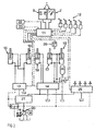
- Figure 2 illustrates an embodiment of a device for controlling a wheel loader.
- the solid lines indicate hydraulic lines, and the dashed lines indicate lines for electric signals.
- the device comprises a central unit 11, or computer, to which the actuation means 1 is connected.
- a number of electric operating levers 12 arranged in the cab are connected to the central unit 11, and this is adapted to handle the signals from the levers.
- a number of electrically controlled hydraulic valves 13, 14 are electrically connected to the central unit 11 and hydraulically connected to a number of working cylinders 15-19 for regulating the reciprocating work of these.
- a pump 20 is also provided in order to supply the working cylinders 15-19 with hydraulic oil via the hydraulic valves 13, 14.
- the working cylinders 15, 16 consist of what are known as steering cylinders and are adapted to turn the wheel loader by means of relative movement of a front and a rear body part.
- the working cylinders 17, 18 consist of what are known as lifting cylinders and are arranged for lifting and lowering a lifting arm unit, on which the implement is mounted.
- the working cylinder 19 consists of what is known as a tilting cylinder and is arranged for tilting, that is to say rotating the implement in the form of, for example, a bucket around a pin of the lifting arm unit. With the aid of the working cylinders 17-19, lifting, lowering, tilting-in and tilting-out movement is therefore obtained for the wheel loader.
- a prioritizing valve 21 is connected between the pump 20 and the electric valves 13, 14. This valve 21 is adapted for prioritising steering hydraulics over lifting hydraulics.
- An accumulator 24 is connected to the loading cylinders 17, 18 in such a way that spring-action characteristics are obtained when the vehicle is driven with a loaded implement.
- the signals from the electric operating levers 12 are converted in a characteristic way in the central unit 11 and are then sent as output signals to the valves 13, 14 in the form of electric pilot hydraulic valves which in turn control the working cylinders 15-19.
- This signal conversion linked to the handling selected affords the driver optimized maneuverability for the handling selected.
- the machine is controlled in the following way in the various operating states (percentages indicate proportion of maximum capacity):
- valve 25 is indicated in Figure 2 .
- This valve 25 is intended to regulate the supply of hydraulic oil to a hydraulic unit of an implement and is coupled hydraulically to the pump 20 via the prioritizing valve 21 and electrically to the central unit 11.
- Said hydraulic unit of the implement can consist of, for example, a working cylinder of the gripping arms for moving these relative to one another or a working cylinder of the fork implement for relative movement of the two legs.
- the prioritizing valve is also adapted to prioritize the steering hydraulics over the hydraulics for the implement concerned.
- Figure 2 also illustrates the engine 22 and transmission 23 of the vehicle, which are coupled electrically to the central unit 11.
- the central unit 11 also handles the signal for economy or performance from the setting element 8 and interprets the maximum speed for the engine 22 and also the selected gear point (speed) for the transmission 23 on the basis of the state selected on the setting element 8 and the control 1.
- the operating parameters which are determined by the operating state selected with the actuation means 1 are not limited to regulating the maximum speed of movement of the implement. According to a development, other specific characteristics of the machine are controlled in various ways depending on the operating state selected. These characteristics can be achieved by virtue of, for example, changing or selecting different algorithms in the gearbox of the machine for different operating states, or changing or selecting different torque curves in the engine.
- the device also comprises means 26 for detection of the position of the implement, or of the loading arm unit.
- This detection means consists of, for example, a sensor of conventional type.
- the detection means 26 is connected to the central unit 11.
- Different detected positions or areas within the movement pattern of the implement or of the loading arm unit correspond to different operating parameters, such as limitations, for example in the form of different maximum speed of movement.
- the implement consists of a bucket, and the maximum speed of movement is limited by a higher limit value when the bucket is located in a lower position in the vertical direction, that is to say close to the ground, and by a lower limit value when the bucket is located in a higher position in the vertical direction. This allows faster bucket movements in lower positions and slower bucket movements in higher positions. It is of course possible to envisage several alternatives or supplements to this illustrative embodiment, for example with limitations of the speed of movement of the loading arm unit depending on where this is located in the lateral direction. It is of course also possible to use more than two different positions or areas.
- the invention is implemented in a wheel loader.
- one of said implements is used for a first use, for example the bucket is used for loading gravel onto the platform of a truck.
- the bucket is replaced with the gripping arm unit.
- the bucket is released from its position on the loading arm unit, and the gripping arm unit is mounted in this position with the aid of the control 7, the driver then changes over to the operating state concerned.
- the invention can of course also be implemented in cases where no exchange of implement is needed, that is to say when two of said implements are intended simultaneously to be arranged in different positions on the construction vehicle.
- Such an example is found in a type of construction machine where the vehicle has a wheel loader unit arranged at the front and an excavating unit arranged at the rear, that is to say what is known as an excavator loader.
- the actuation means can be designed in a number of different ways.
- the actuation means can comprise a set of one or more press-down buttons which each correspond to a specific operating state.
- a linearly guided control can be used.
- the actuation means can comprise a display, on which it is possible to select the intended operating state. The actual selection operation on the display can be effected via a keyboard coupled to the display, or via touch buttons on the display or the like.
- the actuation means is of course not limited to the handling types shown in Figure 1 , but more handling types are of course possible.
- the actuation means being arranged inside the cab of the machine, it can be arranged outside the machine. Furthermore, according to another variant, the actuation means is arranged in the vicinity of the area where the implement is intended to be attached to the machine.
- Each type of implement can be designed with a part characteristic of the type. When the implement is mounted on the machine, this part acts on a correspondingly designed part on the machine, a signal being sent to the central unit and informing it of the type of implement which is mounted on the machine.
- the device can be designed so that the signal transmission between the implement and the machine is effected via signal lines or, alternatively, wirelessly with the aid of an electronic transmitter and receiver.
- a signal can be sent from a sensor which detects which implement is arranged on the machine, and the marking/position 2-4 which corresponds to this implement on the actuation means 1 can light up or be indicated in another way for the driver as a message about which implement is arranged on the machine and a recommendation about which operating state he can/should select.
- the actuation means can be settable in two different positions for the same type of implement. These two positions then correspond to different work situations in which it is desirable for the machine to act in different ways.
- each position relates to an operating state.
- Operating state means a handling type or an area of use, such as pallet handling, lumber handling, gravel/stone handling or sand handling. It is of course possible to use the same implement for different areas of use which require different operating parameters.
- bucket handling can be employed for use in gravel quarries, for transporting sand, or in a mine.
- different implements can be selected for the same type of area of use.
- the individual handling types/tasks/areas of use can instead be illustrated in the various positions on the actuation means.
- the driver can therefore choose to set the control to an area of use which corresponds to the operating parameters according to which he wants the machine to function. According to an example, the driver can therefore use the bucket mode for pallet handling.
- control unit 11 of the vehicle being programmed in order to analyze the driving during the handling selected and optimizing the control of the various operating parameters for this work.
- aspects which can be detected and analyzed by the control unit are how aggressively the driver drives, how much upward slope and downward slope he drives (for example number, length and inclination of the slopes), weight in the bucket (or not), stripping, ploughing, lighting on (or not), outside temperature and engine temperature.
- the control unit therefore analyzes the driving and changes the operating parameters in order to perform the work focussing on, for example, fuel economy.
- the handling type selected by the driver with the actuation means 1 therefore provides input data to the system which acts on hydraulics, engine and transmission. In the case of the transmission, the movement direction is not acted on but remains unaffected. On the other hand, the gear stages, which are to be used, when they are to be activated and how they are engaged, are acted on.
Landscapes
- Engineering & Computer Science (AREA)
- Mining & Mineral Resources (AREA)
- Civil Engineering (AREA)
- General Engineering & Computer Science (AREA)
- Structural Engineering (AREA)
- Mechanical Engineering (AREA)
- Physics & Mathematics (AREA)
- Fluid Mechanics (AREA)
- Operation Control Of Excavators (AREA)
- Feedback Control In General (AREA)
- Shovels (AREA)
- Lighting Device Outwards From Vehicle And Optical Signal (AREA)
- Control Of Position Or Direction (AREA)
- Control Of Positive-Displacement Air Blowers (AREA)
- Heating, Cooling, Or Curing Plastics Or The Like In General (AREA)
- Confectionery (AREA)
- Vending Machines For Individual Products (AREA)
Abstract
Description
- The present invention relates to a device for controlling a machine in several different operating states, the machine being intended to utilize different types of equipment in at least two of these operating states for different activities. Such a device is found in a construction machine in the form of, for example, a wheel loader. The invention will be described below in a case in which it is applied in a wheel loader. This is to be regarded only as an example of a preferred application. The invention also relates to a method for said control.
- A wheel loader can be utilized for a number of different areas of activity, such as lifting and transporting stone and gravel, pallets and logs. For each of these activities, use is made of different equipment comprising implements in the form of a bucket, a fork and gripping arms. Furthermore, the equipment can also comprise one or more working cylinder(s) for operating/moving the implement in question.
- The number of functions in a wheel loader has increased over the years, and the possibilities for different settings of functions has increased in number and complexity. In the wheel loader cab, there are a number of controls for setting and handling said implements. With the greater number of functions and controls, it has become increasingly difficult for the driver to find the optimum settings in order to obtain maximum performance from the machine.
- This problem is more marked in cases where drivers are changed frequently and they do not have such extensive experience of the wheel loader concerned. In these cases, problems often arise with rapidly setting the machine in an optimum way for handling.
US 2001/0032031 discloses the preambles of theindependent claims - A first object of the invention is to produce a device which affords opportunities for simpler, more rapid and/or more reliable handling of a machine which is intended to be operated in several different operating states, which machine is intended to utilize different types of equipment in at least two of these operating states for different activities. Another object is to afford opportunities for more effective use of the machine.
- These objects are achieved by virtue of the fact that the device comprises a means which is intended to be actuated and which can be set in a number of different positions for selection of one of said operating states for the purpose of controlling specific operating parameters corresponding to the operating state selected. With the aid of the actuation means, it is therefore possible to select an operating state which affords optimum opportunities for handling a specific item of equipment.
- According to a preferred embodiment of the invention, said actuation means is adapted for direct operation by the operator of the machine and is also arranged in a cab of the machine. This results in simple and convenient handling for the operator.
- According to another preferred embodiment of the invention, each of said positions corresponds to at least one range for said operating state, and the device comprises a number of controls for controlling/adjusting the equipment within said range. The machine is therefore limited in one or more respect(s) with said range. The limitation can consist of only an upper limit. In a wheel loader, this can be, for example, a limitation of the maximum speed of movement of the implement or the loading arm unit. Said controls consist of, for example, a number of electric control levers.
- According to the invention, the device comprises means for detection of the position of the equipment, and different positions correspond to different ranges. In this way, it is possible, for example, to limit the maximum speed of movement of the equipment to a varying extent depending on the position it is in.
- According to another preferred embodiment of the invention, said equipment comprises an implement intended to be brought into contact with an object or material which is intended to be handled or moved. The equipment also comprises a working cylinder for moving said implement. Here, each of said positions for the actuation means corresponds, for example, to the speed range within which the implement in question can be moved.
- The device also preferably comprises a central unit for controlling said equipment, and the central unit is connected to both said actuation means and said equipment.
- A further object of the invention is to provide a method which affords opportunities for simpler, more rapid and/or more reliable handling of a machine which is intended to be operated in several different operating states, which machine is intended to utilize different types of equipment in at least two of these operating states for different activities. Another object is to afford opportunities for more effective use of the machine.
- These objects are achieved by virtue of the fact that a position of an actuation means is detected and, depending on the position detected, specific operating parameters corresponding to the operating state selected are controller. The method also foresees the step of detecting the position of the equipment. Different detected positions correspond to different ranges of operating states.
- Other preferred embodiments and advantages of the invention emerge from the description and patent claims below.
- The invention will be described in greater detail below with reference to the embodiment shown in the accompanying drawings, in which
- FIG 1
- illustrates a preferred embodiment of a means which is intended to be actuated by an operator and which can be set in a number of different positions, and
- FIG 2
- illustrates diagrammatically a preferred embodiment of a device for controlling a machine.
-
Fig. 1 shows an actuation means 1 comprising acontrol 7 which can be set in several positions 2-6. Thecontrol 7 is of rotary design and is arranged in the instrument panel in the cab of a wheel loader for operation by hand by the driver of the vehicle. The various positions 2-6 define different operating states. Positions 2-4 relate to operating states in which different types of equipment are utilized for moving objects or materials. To be precise,position 2 means that the wheel loader is provided with a fork implement, for example for pallet handling,position 3 means that the wheel loader is provided with a gripping arm unit, for example for lumber handling, andposition 4 means that the wheel loader is provided with a bucket, for example for handling gravel and stone. - The various implements (fork, gripping arms, bucket) are intended for different activities, and there are different requirements for speed and softness of movements etc. in order for the vehicle to function optimally with each of these. Depending on which implement is utilized, it is possible, with the aid of the
control 7, to set the vehicle so that the implement is handled in an optimum way. In other words, a number of operating parameters are controlled by the operating state selected. According to this embodiment, the movements of the machine and the maximum speed of movement of the implement are limited to different extents depending on the operating state selected. -
Position 5 of thecontrol 7 relates to an operating state called "standard which corresponds to an operating parameter compromise which can be used in most handling situations but is not optimized for any specific handling type or any specific implement. "Standard" is therefore a type of universal mode which is to be capable of being used for, for example, snow-ploughing, sweeping etc.Position 6 of thecontrol 7 relates to an operating state called "manual" which means a state in which the driver, or other operating personnel, can personally set operating parameters for more individual implements and/or handling types in order for it to continue to be possible to utilize the wheel loader optimally for these applications. This mode allows the operator, for example, to set parameters for lifting, lowering tilting-in and tilting-out. - The actuation means 1 also comprises
elements economy mode 9 and, respectively, a performance orpower mode 10 in all the operating states mentioned above. Here, said settingelements economy mode 9 is selected, the maximum speed of the engine is limited electronically to an optimum state for the handling type and the machine with regard to economy. Transmission shifting points are also selected electronically for an optimum state for the handling type and the machine with regard to economy. When thepower mode 10 is selected, the maximum speed of the engine is increased electronically to an optimum state for the handling type and the machine with regard to performance. Transmission shifting points are also selected electronically for an optimum state for the handling type and the machine with regard to performance. - This interface between person and machine constitutes a clear and intuitive way of controlling the machine in an optimum manner.
-
Figure 2 illustrates an embodiment of a device for controlling a wheel loader. The solid lines indicate hydraulic lines, and the dashed lines indicate lines for electric signals. The device comprises acentral unit 11, or computer, to which the actuation means 1 is connected. A number of electric operating levers 12 arranged in the cab are connected to thecentral unit 11, and this is adapted to handle the signals from the levers. A number of electrically controlledhydraulic valves central unit 11 and hydraulically connected to a number of working cylinders 15-19 for regulating the reciprocating work of these. Apump 20 is also provided in order to supply the working cylinders 15-19 with hydraulic oil via thehydraulic valves - The working
cylinders cylinders cylinder 19 consists of what is known as a tilting cylinder and is arranged for tilting, that is to say rotating the implement in the form of, for example, a bucket around a pin of the lifting arm unit. With the aid of the working cylinders 17-19, lifting, lowering, tilting-in and tilting-out movement is therefore obtained for the wheel loader. A prioritizingvalve 21 is connected between thepump 20 and theelectric valves valve 21 is adapted for prioritising steering hydraulics over lifting hydraulics. - An
accumulator 24 is connected to theloading cylinders - On the basis of the selected setting of the actuation means 1, the signals from the electric operating levers 12 are converted in a characteristic way in the
central unit 11 and are then sent as output signals to thevalves - According to an operating example, the machine is controlled in the following way in the various operating states (percentages indicate proportion of maximum capacity):
- Pallet handling state (fork implement):
- Reduced lifting speed (suitably 70-85%, preferably 75-80%)
- Reduced lowering speed (suitably 70-85%, preferably 75-80%)
- Reduced tilting speed in (suitably 70-90%, preferably roughly 80%)
- Reduced tilting speed out (suitably 70-80%, preferably roughly 75%)
- Loading arm spring action, determined by the setting of the
accumulator 24, in state speed-dependent
- Lumber handling state (gripping arm unit):
- Reduced lifting speed (suitably 70-90%, preferably roughly 80%)
- Reduced lowering speed (suitably 70-90%, preferably roughly 80%)
- Reduced tilting speed in (suitably 80-90%, preferably roughly 85%)
- Reduced tilting speed out (suitably 70-85%, preferably 75-80%)
- Loading arm spring action, determined by the setting of the
accumulator 24, in state speed-dependent
- Bucket handling state:
- Full lifting speed (100%)
- High lowering speed (> 95%)
- High tilting speed in (> 95%)
- High tilting speed out (> 90%)
- Loading arm spring action, determined by the setting of the
accumulator 24, in state gear-dependent
- Standard state
- Normal lifting speed (suitably 80-90%, preferably roughly 85%)
- Normal lowering speed (suitably 85-95%, preferably roughly 90%)
- Normal tilting speed in (suitably 85-95%, preferably roughly 90%)
- Normal tilting speed out (suitably 80-90%, preferably roughly 85%)
- Loading arm spring action, determined by the setting of the
accumulator 24, in state selectable between gear-dependent and speed-dependent and also turned-off state.
- Manual state:
- Adjustable lifting speed (basic value roughly 85%; variable 50%-100%)
- Adjustable lowering speed (basic value roughly 90%,; variable 50%-100%)
- Adjustable tilting speed in (basic value roughly 90%; variable 50%-100%)
- Adjustable tilting speed out (basic value roughly 85%; variable 50%-100%)
- Loading arm spring action, determined by the setting of the
accumulator 24, in state selectable between gear-dependent and speed-dependent and also turned-off state.
- Another
valve 25 is indicated inFigure 2 . Thisvalve 25 is intended to regulate the supply of hydraulic oil to a hydraulic unit of an implement and is coupled hydraulically to thepump 20 via the prioritizingvalve 21 and electrically to thecentral unit 11. Said hydraulic unit of the implement can consist of, for example, a working cylinder of the gripping arms for moving these relative to one another or a working cylinder of the fork implement for relative movement of the two legs. The prioritizing valve is also adapted to prioritize the steering hydraulics over the hydraulics for the implement concerned. -
Figure 2 also illustrates theengine 22 andtransmission 23 of the vehicle, which are coupled electrically to thecentral unit 11. In addition to the signal from thecontrol 1, thecentral unit 11 also handles the signal for economy or performance from the settingelement 8 and interprets the maximum speed for theengine 22 and also the selected gear point (speed) for thetransmission 23 on the basis of the state selected on thesetting element 8 and thecontrol 1. - The operating parameters which are determined by the operating state selected with the actuation means 1 are not limited to regulating the maximum speed of movement of the implement. According to a development, other specific characteristics of the machine are controlled in various ways depending on the operating state selected. These characteristics can be achieved by virtue of, for example, changing or selecting different algorithms in the gearbox of the machine for different operating states, or changing or selecting different torque curves in the engine.
- The device also comprises means 26 for detection of the position of the implement, or of the loading arm unit. This detection means consists of, for example, a sensor of conventional type. The detection means 26 is connected to the
central unit 11. Different detected positions or areas within the movement pattern of the implement or of the loading arm unit correspond to different operating parameters, such as limitations, for example in the form of different maximum speed of movement. According to one illustrative embodiment, the implement consists of a bucket, and the maximum speed of movement is limited by a higher limit value when the bucket is located in a lower position in the vertical direction, that is to say close to the ground, and by a lower limit value when the bucket is located in a higher position in the vertical direction. This allows faster bucket movements in lower positions and slower bucket movements in higher positions. It is of course possible to envisage several alternatives or supplements to this illustrative embodiment, for example with limitations of the speed of movement of the loading arm unit depending on where this is located in the lateral direction. It is of course also possible to use more than two different positions or areas. - According to the description above, the invention is implemented in a wheel loader. In this case, one of said implements is used for a first use, for example the bucket is used for loading gravel onto the platform of a truck. When it is desired to utilize the wheel loader for another use, such as loading logs, the bucket is replaced with the gripping arm unit. In other words, the bucket is released from its position on the loading arm unit, and the gripping arm unit is mounted in this position with the aid of the
control 7, the driver then changes over to the operating state concerned. The invention can of course also be implemented in cases where no exchange of implement is needed, that is to say when two of said implements are intended simultaneously to be arranged in different positions on the construction vehicle. Such an example is found in a type of construction machine where the vehicle has a wheel loader unit arranged at the front and an excavating unit arranged at the rear, that is to say what is known as an excavator loader. - The invention is not to be considered as being limited to the illustrative embodiments described above, but a number of further variants and modifications are conceivable within the scope of the patent claims below. For example, the hydraulic system described in
Figure 2 is to be regarded only as an example. The invention can also be implemented with separate hydraulic systems for steering and loading. - Within the scope of the invention, it is of course possible for the actuation means to be designed in a number of different ways. For example, the actuation means can comprise a set of one or more press-down buttons which each correspond to a specific operating state. Alternatively, a linearly guided control can be used. As a further alternative, the actuation means can comprise a display, on which it is possible to select the intended operating state. The actual selection operation on the display can be effected via a keyboard coupled to the display, or via touch buttons on the display or the like.
- The actuation means is of course not limited to the handling types shown in
Figure 1 , but more handling types are of course possible. - According to an alternative to the actuation means being arranged inside the cab of the machine, it can be arranged outside the machine. Furthermore, according to another variant, the actuation means is arranged in the vicinity of the area where the implement is intended to be attached to the machine. Each type of implement can be designed with a part characteristic of the type. When the implement is mounted on the machine, this part acts on a correspondingly designed part on the machine, a signal being sent to the central unit and informing it of the type of implement which is mounted on the machine. The device can be designed so that the signal transmission between the implement and the machine is effected via signal lines or, alternatively, wirelessly with the aid of an electronic transmitter and receiver.
- According to a development of the preceding alternative, a signal can be sent from a sensor which detects which implement is arranged on the machine, and the marking/position 2-4 which corresponds to this implement on the actuation means 1 can light up or be indicated in another way for the driver as a message about which implement is arranged on the machine and a recommendation about which operating state he can/should select.
- According to an alternative to the embodiment described above, the actuation means can be settable in two different positions for the same type of implement. These two positions then correspond to different work situations in which it is desirable for the machine to act in different ways.
- Although the markings for the different positions 2-4 on the actuation means 1 according to the preferred embodiment indicate different implements (fork implement, gripping arms, bucket), each position relates to an operating state. Operating state means a handling type or an area of use, such as pallet handling, lumber handling, gravel/stone handling or sand handling. It is of course possible to use the same implement for different areas of use which require different operating parameters. For example, bucket handling can be employed for use in gravel quarries, for transporting sand, or in a mine. Likewise, different implements can be selected for the same type of area of use. According to an alternative, therefore, the individual handling types/tasks/areas of use can instead be illustrated in the various positions on the actuation means. The driver can therefore choose to set the control to an area of use which corresponds to the operating parameters according to which he wants the machine to function. According to an example, the driver can therefore use the bucket mode for pallet handling.
- According to another alternative, it is possible to envisage the
control unit 11 of the vehicle being programmed in order to analyze the driving during the handling selected and optimizing the control of the various operating parameters for this work. Examples of aspects which can be detected and analyzed by the control unit are how aggressively the driver drives, how much upward slope and downward slope he drives (for example number, length and inclination of the slopes), weight in the bucket (or not), stripping, ploughing, lighting on (or not), outside temperature and engine temperature. The control unit therefore analyzes the driving and changes the operating parameters in order to perform the work focussing on, for example, fuel economy. - The handling type selected by the driver with the actuation means 1 therefore provides input data to the system which acts on hydraulics, engine and transmission. In the case of the transmission, the movement direction is not acted on but remains unaffected. On the other hand, the gear stages, which are to be used, when they are to be activated and how they are engaged, are acted on.
Claims (18)
- A device for controlling a machine in several different operating states, the machine being intended to utilize different types of equipment in at least two of these operating states for different activities, which device comprises a means (1) which is intended to be actuated and which can be set in a number of different positions (2-6) for selection of one of said operating states for the purpose of controlling specific operating parameters corresponding to the operating state selected, and in which each of said positions corresponds to at least one range for said operating state, and in that the device comprises a number of controls (12) for controlling/adjusting the equipment within said range characterized in that the device comprises means (26) for detection of the position of the equipment, and in that different positions correspond to different ranges.
- The device as claimed in claim 1, characterized in that said actuation means (1) is adapted for direct operation by the operator of the machine.
- The device as claimed in claim 2, characterized in that said actuation means (1) is arranged in a cab of the machine.
- The device as claimed in any one of the preceding claims, characterized in that said machine consists of a vehicle.
- The device as claimed in any one of the preceding claims, characterized in that said machine consists of a construction vehicle.
- The device as claimed in claim 5, characterized in that said equipment comprises an implement intended to be brought into contact with an object or material which is intended to be handled or moved.
- The device as claimed in claim 6, characterized in that each of said positions (2-6) corresponds to the speed range within which the implement in question can be moved.
- The device as claimed in claim 6 or 7, characterized in that one of said implements consists of a bucket.
- The device as claimed in any one of claims 6-8, characterized in that one of said implements consists of a fork implement.
- The device as claimed in any one of claims 6-9, characterized in that one of said implements consists of a gripping arm unit.
- The device as claimed in any one of claims 6-10, characterized in that at least two of said implements are interchangeable for mounting in the same position.
- The device as claimed in any one of claims 6-11, characterized in that at least two of said implements are intended simultaneously to be arranged in different positions on the construction vehicle.
- The device as claimed in any one of claims 6-12, characterized in that said equipment comprises a working cylinder (17-19) for movement of said implements.
- The device as claimed in any one of the preceding claims, characterized in that the device comprises a central unit (11) for controlling said equipment, and in that the central unit is connected to both said actuation means (1) and said equipment.
- The device as claimed in any one of the preceding claims, characterized in that one of said positions for said actuation means (1) corresponds to an operating state which in turn corresponds to a compromise of a number of different operating states with different equipment.
- The device as claimed in any one of the preceding claims, characterized in that said actuation means is adapted to allow setting of economic operation in terms of fuel consumption irrespective of the operating state concerned.
- A method for controlling a machine in several different operating states, the machine being intended to utilize different types of equipment in at least two of these operating states for different activities, a position of an actuation means (1) is detected and, depending on the position detected, specific operating parameters corresponding to the operating state selected are controlled, and in which each of said positions corresponds to at least one range for said operating state, and in that operation of a number of controls (12) is detected for controlling/adjusting the equipment within said range characterized in that the position of the equipment is detected, and in that different positions correspond to different ranges.
- The method as claimed in claim 17, characterized in that said machine consists of a construction vehicle.
Applications Claiming Priority (3)
| Application Number | Priority Date | Filing Date | Title |
|---|---|---|---|
| SE0201196 | 2002-04-22 | ||
| SE0201196A SE523988C2 (en) | 2002-04-22 | 2002-04-22 | Device and method for controlling a machine |
| PCT/SE2003/000649 WO2003089723A1 (en) | 2002-04-22 | 2003-04-17 | Device and method for controlling a machine. |
Publications (2)
| Publication Number | Publication Date |
|---|---|
| EP1507932A1 EP1507932A1 (en) | 2005-02-23 |
| EP1507932B1 true EP1507932B1 (en) | 2010-07-14 |
Family
ID=20287633
Family Applications (1)
| Application Number | Title | Priority Date | Filing Date |
|---|---|---|---|
| EP03721231A Expired - Lifetime EP1507932B1 (en) | 2002-04-22 | 2003-04-17 | Device and method for controlling a machine comprising an equipment |
Country Status (9)
| Country | Link |
|---|---|
| US (1) | US7856301B2 (en) |
| EP (1) | EP1507932B1 (en) |
| JP (1) | JP4468703B2 (en) |
| CN (1) | CN100378276C (en) |
| AT (1) | ATE474094T1 (en) |
| AU (1) | AU2003235347A1 (en) |
| DE (1) | DE60333359D1 (en) |
| SE (1) | SE523988C2 (en) |
| WO (1) | WO2003089723A1 (en) |
Families Citing this family (21)
| Publication number | Priority date | Publication date | Assignee | Title |
|---|---|---|---|---|
| SE523988C2 (en) | 2002-04-22 | 2004-06-15 | Volvo Constr Equip Holding Se | Device and method for controlling a machine |
| EP1776538B1 (en) | 2004-07-27 | 2008-04-16 | Volvo Construction Equipment AB | A method and a device for controlling movements of a work vehicle |
| US20080319618A1 (en) * | 2006-02-20 | 2008-12-25 | Volvo Construction Equipment Ab | Method for Optimizing Operation of a Work Vehicle |
| US9126598B2 (en) * | 2006-06-05 | 2015-09-08 | Deere & Company | Power management for infinitely variable transmission (IVT) equipped machines |
| JP5121405B2 (en) * | 2007-11-13 | 2013-01-16 | 株式会社小松製作所 | Engine control device for construction machinery |
| KR101550325B1 (en) * | 2008-06-03 | 2015-09-04 | 볼보 컨스트럭션 이큅먼트 에이비 | A method for controlling a power source |
| DE102008043106A1 (en) * | 2008-10-23 | 2010-04-29 | Zf Friedrichshafen Ag | Method for operating the lockup clutch in a power shift transmission of a work machine comprising at least one hydraulically actuated lifting device |
| US8463508B2 (en) * | 2009-12-18 | 2013-06-11 | Caterpillar Inc. | Implement angle correction system and associated loader |
| KR101637575B1 (en) * | 2009-12-24 | 2016-07-07 | 두산인프라코어 주식회사 | Hydraulic control apparatus for construction machinery |
| JP5261419B2 (en) * | 2010-03-05 | 2013-08-14 | 株式会社小松製作所 | Work vehicle and control method of work vehicle |
| US20120123614A1 (en) * | 2010-11-17 | 2012-05-17 | INRO Technologies Limited | Method and apparatus for virtualizing industrial vehicles to automate task execution in a physical environment |
| US8978276B2 (en) | 2012-08-16 | 2015-03-17 | The Toro Company | Safety systems for wireless control for snow plows |
| US9194091B2 (en) | 2012-08-16 | 2015-11-24 | The Toro Company | Wireless snow plow control |
| US20140053801A1 (en) | 2012-08-23 | 2014-02-27 | Caterpillar Paving Products | Autoadaptive Engine Idle Speed Control |
| JP6209439B2 (en) * | 2013-12-19 | 2017-10-04 | ナブテスコ株式会社 | Directional switching valve for construction machine, opening determination device thereof, and opening determination method thereof |
| US20150226317A1 (en) * | 2014-02-13 | 2015-08-13 | GM Global Technology Operations LLC | Mono-stable rotary transmission selector |
| JP2016147754A (en) * | 2015-02-13 | 2016-08-18 | 株式会社タダノ | Actuator control device and work vehicle |
| CN109511268A (en) * | 2017-07-14 | 2019-03-22 | 株式会社小松制作所 | Working machine and control method of working machine |
| US10487478B2 (en) | 2017-10-12 | 2019-11-26 | Caterpillar Inc. | Wireless system and method for connected work tool identification |
| US11365801B2 (en) | 2019-08-28 | 2022-06-21 | Donovan Knutson | Utility vehicle having adaptive drive limiting control |
| DE102021212458A1 (en) * | 2021-11-05 | 2023-05-11 | Zf Friedrichshafen Ag | Method for operating a drive train of a working machine |
Family Cites Families (38)
| Publication number | Priority date | Publication date | Assignee | Title |
|---|---|---|---|---|
| US2848902A (en) * | 1956-03-27 | 1958-08-26 | Shakespeare Products Co | Drive selector mechanism |
| US3633679A (en) * | 1969-10-13 | 1972-01-11 | Fmc Corp | Mobile self-supporting tiller |
| JPS5931458Y2 (en) * | 1978-08-24 | 1984-09-06 | 株式会社クボタ | Operating structure of swing work vehicle |
| US4610335A (en) * | 1982-11-10 | 1986-09-09 | Honda Giken Kogyo Kabushiki Kaisha | Control device for clutch and transmission in vehicles |
| US4548094A (en) * | 1983-03-03 | 1985-10-22 | J. I. Case Company | Handle control assembly |
| AT378615B (en) * | 1984-02-01 | 1985-09-10 | Steyr Daimler Puch Ag | AUXILIARY DEVICE FOR OBTAINING OPTIMAL VALUES FOR COMMERCIAL VEHICLES |
| JPH0214693Y2 (en) * | 1984-09-29 | 1990-04-20 | ||
| US4727710A (en) * | 1986-05-30 | 1988-03-01 | Deutz-Allis Corporation | Automatic vehicle ground speed control convertible to manual operation |
| DE3886944T2 (en) * | 1988-05-24 | 1994-05-05 | Komatsu Mfg Co Ltd | AUTOMATIC GEARBOX FOR WHEEL LIFTING DEVICE. |
| SE465962B (en) * | 1989-02-16 | 1991-11-25 | Recodrive Ab | ADDITION TO THE VEHICLE |
| JPH0662270B2 (en) * | 1989-05-10 | 1994-08-17 | 株式会社神戸製鋼所 | Displacement restraint device for mobile crane |
| EP0715102B1 (en) | 1991-03-13 | 2005-06-01 | Mitsubishi Jidosha Kogyo Kabushiki Kaisha | Speed change control method for an automatic transmission for vehicles |
| US5346035A (en) * | 1993-01-04 | 1994-09-13 | Nippon Yusen Kaisha | Fork lift truck with rotatable seat and operator controls |
| AU664517B2 (en) * | 1993-05-28 | 1995-11-16 | Kubota Corporation | Hydraulic control system |
| DE4434022C2 (en) * | 1994-09-23 | 1999-11-11 | Daimler Chrysler Ag | Method and device for limiting the speed of a motor vehicle |
| DE19521795A1 (en) * | 1995-06-16 | 1996-12-19 | Zahnradfabrik Friedrichshafen | Electro-mechanical superimposed steering gear for a tracked vehicle |
| DE19706625B4 (en) * | 1996-03-01 | 2006-05-04 | Volkswagen Ag | Speed control device for an automatic transmission |
| KR100272912B1 (en) * | 1996-11-19 | 2000-12-01 | 하나와 요시카즈 | Car driving force control device |
| JPH10237904A (en) * | 1997-02-25 | 1998-09-08 | Shin Caterpillar Mitsubishi Ltd | Method of controlling construction machinery and device thereof |
| US6064933A (en) * | 1997-05-16 | 2000-05-16 | Caterpillar Inc. | Automatic bucket loading using teaching and playback modes triggered by pile contact |
| DE19731089A1 (en) * | 1997-07-19 | 1999-01-21 | Bosch Gmbh Robert | Device for determining the weight of articulated loads |
| US6448670B1 (en) * | 1998-05-12 | 2002-09-10 | Alps Electric Co., Ltd. | Signal input device |
| GB2349482B (en) * | 1998-12-22 | 2003-07-09 | Caterpillar Inc | Tool recognition and control system for a work machine |
| US6249727B1 (en) * | 1999-05-19 | 2001-06-19 | Caterpillar Inc. | Method and apparatus for customizing and limiting operation of machine subsystems |
| US6330502B1 (en) * | 2000-05-23 | 2001-12-11 | Caterpillar Inc. | Method and system for selecting desired response of an electronic-controlled sub-system |
| US6661114B2 (en) * | 2000-05-31 | 2003-12-09 | Kabushiki Kaisha Tokai Rika Denki Seisakusho | Shift apparatus for vehicles |
| JP4489258B2 (en) * | 2000-07-17 | 2010-06-23 | 日立建機株式会社 | Electronic control system for construction machinery |
| US6336068B1 (en) * | 2000-09-20 | 2002-01-01 | Caterpillar Inc. | Control system for wheel tractor scrapers |
| FR2814552B1 (en) * | 2000-09-28 | 2003-01-24 | Renault Agriculture | SYSTEM AND METHOD FOR CONTROLLING TOOLS AND CORRESPONDING EQUIPMENT |
| KR100373026B1 (en) * | 2000-10-17 | 2003-02-25 | 현대자동차주식회사 | Transmission control system and method thereof |
| US6427107B1 (en) * | 2001-06-28 | 2002-07-30 | Caterpillar Inc. | Power management system and method |
| DE10064860A1 (en) * | 2000-12-23 | 2002-06-27 | Claas Selbstfahr Erntemasch | Harvested crop transfer optimisation device uses control unit providing signals for controlling velocity and steering angle of crop transport vehicle adjacent harvesting machine |
| US6564661B2 (en) * | 2001-02-01 | 2003-05-20 | Grand Haven Stamped Products, Division Of Jsj Corporation | Storable shifter with electronic gear shift reset |
| JP4497741B2 (en) * | 2001-03-29 | 2010-07-07 | 株式会社小松製作所 | Steering device for tracked vehicle |
| US6851495B2 (en) * | 2001-10-19 | 2005-02-08 | Deere & Co. | Speed control for utility vehicle operable from rearward-facing seat |
| US20050115760A1 (en) * | 2001-10-19 | 2005-06-02 | Sprinkle David L. | Speed control for utility vehicle operable from rearward-facing seat |
| US6865870B2 (en) * | 2002-01-10 | 2005-03-15 | Cnh America Llc | Combine power selection system |
| SE523988C2 (en) | 2002-04-22 | 2004-06-15 | Volvo Constr Equip Holding Se | Device and method for controlling a machine |
-
2002
- 2002-04-22 SE SE0201196A patent/SE523988C2/en not_active IP Right Cessation
-
2003
- 2003-04-17 WO PCT/SE2003/000649 patent/WO2003089723A1/en not_active Ceased
- 2003-04-17 DE DE60333359T patent/DE60333359D1/en not_active Expired - Lifetime
- 2003-04-17 EP EP03721231A patent/EP1507932B1/en not_active Expired - Lifetime
- 2003-04-17 CN CNB038090279A patent/CN100378276C/en not_active Expired - Lifetime
- 2003-04-17 JP JP2003586427A patent/JP4468703B2/en not_active Expired - Fee Related
- 2003-04-17 AT AT03721231T patent/ATE474094T1/en not_active IP Right Cessation
- 2003-04-17 AU AU2003235347A patent/AU2003235347A1/en not_active Abandoned
-
2004
- 2004-10-22 US US10/904,102 patent/US7856301B2/en active Active
Also Published As
| Publication number | Publication date |
|---|---|
| AU2003235347A1 (en) | 2003-11-03 |
| SE0201196D0 (en) | 2002-04-22 |
| WO2003089723A1 (en) | 2003-10-30 |
| CN100378276C (en) | 2008-04-02 |
| JP2005523392A (en) | 2005-08-04 |
| US20080040006A1 (en) | 2008-02-14 |
| SE523988C2 (en) | 2004-06-15 |
| SE0201196L (en) | 2003-10-23 |
| JP4468703B2 (en) | 2010-05-26 |
| DE60333359D1 (en) | 2010-08-26 |
| CN1646775A (en) | 2005-07-27 |
| ATE474094T1 (en) | 2010-07-15 |
| EP1507932A1 (en) | 2005-02-23 |
| US7856301B2 (en) | 2010-12-21 |
Similar Documents
| Publication | Publication Date | Title |
|---|---|---|
| EP1507932A1 (en) | Device and method for controlling a machine. | |
| US7099722B2 (en) | Work machine attachment control system | |
| US7539570B2 (en) | Machine operating system and method | |
| AU2004202637B2 (en) | Tactile feedback system for a remotely controlled work machine | |
| CN101072917A (en) | Work machine operating system and method | |
| US8695333B2 (en) | Method for when necessary automatically limiting a pressure in a hydraulic system during operation | |
| US11698086B2 (en) | Systems and methods to control movement of a work vehicle attachment | |
| CN102667014A (en) | Electrohydraulic control device and method using variable behavior characteristics | |
| US9790660B1 (en) | Control system for a machine | |
| EP3725952B1 (en) | Systems and methods for control of a work vehicle | |
| EP1947316B1 (en) | Engine controller of hydraulic shovel | |
| EP2281092B1 (en) | A method for controlling a hydraulic system | |
| EP2209950B1 (en) | Method for controlling a working machine | |
| EP2155972B1 (en) | Power machine or vehicle with power management | |
| EP3719217B1 (en) | A control method for actuating a return-to-dig movement of an implement, such as a bucket, in a work vehicle, a corresponding control system and a work vehicle comprising such control system | |
| CN108691329B (en) | Oil mass control method of engineering machinery and system for executing same | |
| EP3719220B1 (en) | A control method of actuating a movement of at least one of a boom and an implement connected to the boom in a work vehicle powered by a motor, a corresponding control system and a work vehicle comprising such control system | |
| JP2546294B2 (en) | Loader operation device | |
| KR100438928B1 (en) | Hydraulic control appratus for fine control of an excavator | |
| US20250207358A1 (en) | Control System for Ripper Operation | |
| JP5541912B2 (en) | Tractor |
Legal Events
| Date | Code | Title | Description |
|---|---|---|---|
| PUAI | Public reference made under article 153(3) epc to a published international application that has entered the european phase |
Free format text: ORIGINAL CODE: 0009012 |
|
| 17P | Request for examination filed |
Effective date: 20041122 |
|
| AK | Designated contracting states |
Kind code of ref document: A1 Designated state(s): AT BE BG CH CY CZ DE DK EE ES FI FR GB GR HU IE IT LI LU MC NL PT RO SE SI SK TR |
|
| AX | Request for extension of the european patent |
Extension state: AL LT LV MK |
|
| GRAP | Despatch of communication of intention to grant a patent |
Free format text: ORIGINAL CODE: EPIDOSNIGR1 |
|
| RTI1 | Title (correction) |
Free format text: DEVICE AND METHOD FOR CONTROLLING A MACHINE COMPRISING AN EQUIPMENT |
|
| GRAS | Grant fee paid |
Free format text: ORIGINAL CODE: EPIDOSNIGR3 |
|
| GRAA | (expected) grant |
Free format text: ORIGINAL CODE: 0009210 |
|
| AK | Designated contracting states |
Kind code of ref document: B1 Designated state(s): AT BE BG CH CY CZ DE DK EE ES FI FR GB GR HU IE IT LI LU MC NL PT RO SE SI SK TR |
|
| REG | Reference to a national code |
Ref country code: GB Ref legal event code: FG4D |
|
| REG | Reference to a national code |
Ref country code: CH Ref legal event code: EP |
|
| REG | Reference to a national code |
Ref country code: IE Ref legal event code: FG4D |
|
| REF | Corresponds to: |
Ref document number: 60333359 Country of ref document: DE Date of ref document: 20100826 Kind code of ref document: P |
|
| REG | Reference to a national code |
Ref country code: NL Ref legal event code: VDEP Effective date: 20100714 |
|
| PG25 | Lapsed in a contracting state [announced via postgrant information from national office to epo] |
Ref country code: AT Free format text: LAPSE BECAUSE OF FAILURE TO SUBMIT A TRANSLATION OF THE DESCRIPTION OR TO PAY THE FEE WITHIN THE PRESCRIBED TIME-LIMIT Effective date: 20100714 Ref country code: NL Free format text: LAPSE BECAUSE OF FAILURE TO SUBMIT A TRANSLATION OF THE DESCRIPTION OR TO PAY THE FEE WITHIN THE PRESCRIBED TIME-LIMIT Effective date: 20100714 Ref country code: FI Free format text: LAPSE BECAUSE OF FAILURE TO SUBMIT A TRANSLATION OF THE DESCRIPTION OR TO PAY THE FEE WITHIN THE PRESCRIBED TIME-LIMIT Effective date: 20100714 |
|
| PG25 | Lapsed in a contracting state [announced via postgrant information from national office to epo] |
Ref country code: PT Free format text: LAPSE BECAUSE OF FAILURE TO SUBMIT A TRANSLATION OF THE DESCRIPTION OR TO PAY THE FEE WITHIN THE PRESCRIBED TIME-LIMIT Effective date: 20101115 Ref country code: CY Free format text: LAPSE BECAUSE OF FAILURE TO SUBMIT A TRANSLATION OF THE DESCRIPTION OR TO PAY THE FEE WITHIN THE PRESCRIBED TIME-LIMIT Effective date: 20100714 Ref country code: SI Free format text: LAPSE BECAUSE OF FAILURE TO SUBMIT A TRANSLATION OF THE DESCRIPTION OR TO PAY THE FEE WITHIN THE PRESCRIBED TIME-LIMIT Effective date: 20100714 Ref country code: BG Free format text: LAPSE BECAUSE OF FAILURE TO SUBMIT A TRANSLATION OF THE DESCRIPTION OR TO PAY THE FEE WITHIN THE PRESCRIBED TIME-LIMIT Effective date: 20101014 |
|
| PG25 | Lapsed in a contracting state [announced via postgrant information from national office to epo] |
Ref country code: GR Free format text: LAPSE BECAUSE OF FAILURE TO SUBMIT A TRANSLATION OF THE DESCRIPTION OR TO PAY THE FEE WITHIN THE PRESCRIBED TIME-LIMIT Effective date: 20101015 Ref country code: SE Free format text: LAPSE BECAUSE OF FAILURE TO SUBMIT A TRANSLATION OF THE DESCRIPTION OR TO PAY THE FEE WITHIN THE PRESCRIBED TIME-LIMIT Effective date: 20100714 Ref country code: BE Free format text: LAPSE BECAUSE OF FAILURE TO SUBMIT A TRANSLATION OF THE DESCRIPTION OR TO PAY THE FEE WITHIN THE PRESCRIBED TIME-LIMIT Effective date: 20100714 |
|
| PG25 | Lapsed in a contracting state [announced via postgrant information from national office to epo] |
Ref country code: DK Free format text: LAPSE BECAUSE OF FAILURE TO SUBMIT A TRANSLATION OF THE DESCRIPTION OR TO PAY THE FEE WITHIN THE PRESCRIBED TIME-LIMIT Effective date: 20100714 |
|
| PLBE | No opposition filed within time limit |
Free format text: ORIGINAL CODE: 0009261 |
|
| STAA | Information on the status of an ep patent application or granted ep patent |
Free format text: STATUS: NO OPPOSITION FILED WITHIN TIME LIMIT |
|
| PG25 | Lapsed in a contracting state [announced via postgrant information from national office to epo] |
Ref country code: CZ Free format text: LAPSE BECAUSE OF FAILURE TO SUBMIT A TRANSLATION OF THE DESCRIPTION OR TO PAY THE FEE WITHIN THE PRESCRIBED TIME-LIMIT Effective date: 20100714 Ref country code: EE Free format text: LAPSE BECAUSE OF FAILURE TO SUBMIT A TRANSLATION OF THE DESCRIPTION OR TO PAY THE FEE WITHIN THE PRESCRIBED TIME-LIMIT Effective date: 20100714 Ref country code: IT Free format text: LAPSE BECAUSE OF FAILURE TO SUBMIT A TRANSLATION OF THE DESCRIPTION OR TO PAY THE FEE WITHIN THE PRESCRIBED TIME-LIMIT Effective date: 20100714 Ref country code: SK Free format text: LAPSE BECAUSE OF FAILURE TO SUBMIT A TRANSLATION OF THE DESCRIPTION OR TO PAY THE FEE WITHIN THE PRESCRIBED TIME-LIMIT Effective date: 20100714 Ref country code: RO Free format text: LAPSE BECAUSE OF FAILURE TO SUBMIT A TRANSLATION OF THE DESCRIPTION OR TO PAY THE FEE WITHIN THE PRESCRIBED TIME-LIMIT Effective date: 20100714 |
|
| 26N | No opposition filed |
Effective date: 20110415 |
|
| PG25 | Lapsed in a contracting state [announced via postgrant information from national office to epo] |
Ref country code: ES Free format text: LAPSE BECAUSE OF FAILURE TO SUBMIT A TRANSLATION OF THE DESCRIPTION OR TO PAY THE FEE WITHIN THE PRESCRIBED TIME-LIMIT Effective date: 20101025 |
|
| REG | Reference to a national code |
Ref country code: DE Ref legal event code: R097 Ref document number: 60333359 Country of ref document: DE Effective date: 20110415 |
|
| PG25 | Lapsed in a contracting state [announced via postgrant information from national office to epo] |
Ref country code: MC Free format text: LAPSE BECAUSE OF NON-PAYMENT OF DUE FEES Effective date: 20110430 |
|
| REG | Reference to a national code |
Ref country code: CH Ref legal event code: PL |
|
| REG | Reference to a national code |
Ref country code: FR Ref legal event code: ST Effective date: 20111230 |
|
| PG25 | Lapsed in a contracting state [announced via postgrant information from national office to epo] |
Ref country code: LI Free format text: LAPSE BECAUSE OF NON-PAYMENT OF DUE FEES Effective date: 20110430 Ref country code: FR Free format text: LAPSE BECAUSE OF NON-PAYMENT OF DUE FEES Effective date: 20110502 Ref country code: CH Free format text: LAPSE BECAUSE OF NON-PAYMENT OF DUE FEES Effective date: 20110430 |
|
| REG | Reference to a national code |
Ref country code: IE Ref legal event code: MM4A |
|
| PG25 | Lapsed in a contracting state [announced via postgrant information from national office to epo] |
Ref country code: IE Free format text: LAPSE BECAUSE OF NON-PAYMENT OF DUE FEES Effective date: 20110417 |
|
| PG25 | Lapsed in a contracting state [announced via postgrant information from national office to epo] |
Ref country code: LU Free format text: LAPSE BECAUSE OF NON-PAYMENT OF DUE FEES Effective date: 20110417 |
|
| PG25 | Lapsed in a contracting state [announced via postgrant information from national office to epo] |
Ref country code: TR Free format text: LAPSE BECAUSE OF FAILURE TO SUBMIT A TRANSLATION OF THE DESCRIPTION OR TO PAY THE FEE WITHIN THE PRESCRIBED TIME-LIMIT Effective date: 20100714 |
|
| PG25 | Lapsed in a contracting state [announced via postgrant information from national office to epo] |
Ref country code: HU Free format text: LAPSE BECAUSE OF FAILURE TO SUBMIT A TRANSLATION OF THE DESCRIPTION OR TO PAY THE FEE WITHIN THE PRESCRIBED TIME-LIMIT Effective date: 20100714 |
|
| PGFP | Annual fee paid to national office [announced via postgrant information from national office to epo] |
Ref country code: GB Payment date: 20220419 Year of fee payment: 20 Ref country code: DE Payment date: 20220428 Year of fee payment: 20 |
|
| REG | Reference to a national code |
Ref country code: DE Ref legal event code: R071 Ref document number: 60333359 Country of ref document: DE |
|
| REG | Reference to a national code |
Ref country code: GB Ref legal event code: PE20 Expiry date: 20230416 |
|
| PG25 | Lapsed in a contracting state [announced via postgrant information from national office to epo] |
Ref country code: GB Free format text: LAPSE BECAUSE OF EXPIRATION OF PROTECTION Effective date: 20230416 |