EP1507582B1 - Bubble humidifier with improved diffuser and pressure relief device - Google Patents
Bubble humidifier with improved diffuser and pressure relief device Download PDFInfo
- Publication number
- EP1507582B1 EP1507582B1 EP03728898A EP03728898A EP1507582B1 EP 1507582 B1 EP1507582 B1 EP 1507582B1 EP 03728898 A EP03728898 A EP 03728898A EP 03728898 A EP03728898 A EP 03728898A EP 1507582 B1 EP1507582 B1 EP 1507582B1
- Authority
- EP
- European Patent Office
- Prior art keywords
- oxygen
- humidifier
- bubble
- bubble humidifier
- pressure relief
- Prior art date
- Legal status (The legal status is an assumption and is not a legal conclusion. Google has not performed a legal analysis and makes no representation as to the accuracy of the status listed.)
- Expired - Lifetime
Links
Images



Classifications
-
- A—HUMAN NECESSITIES
- A61—MEDICAL OR VETERINARY SCIENCE; HYGIENE
- A61M—DEVICES FOR INTRODUCING MEDIA INTO, OR ONTO, THE BODY; DEVICES FOR TRANSDUCING BODY MEDIA OR FOR TAKING MEDIA FROM THE BODY; DEVICES FOR PRODUCING OR ENDING SLEEP OR STUPOR
- A61M16/00—Devices for influencing the respiratory system of patients by gas treatment, e.g. ventilators; Tracheal tubes
- A61M16/20—Valves specially adapted to medical respiratory devices
- A61M16/208—Non-controlled one-way valves, e.g. exhalation, check, pop-off non-rebreathing valves
-
- A—HUMAN NECESSITIES
- A61—MEDICAL OR VETERINARY SCIENCE; HYGIENE
- A61M—DEVICES FOR INTRODUCING MEDIA INTO, OR ONTO, THE BODY; DEVICES FOR TRANSDUCING BODY MEDIA OR FOR TAKING MEDIA FROM THE BODY; DEVICES FOR PRODUCING OR ENDING SLEEP OR STUPOR
- A61M16/00—Devices for influencing the respiratory system of patients by gas treatment, e.g. ventilators; Tracheal tubes
- A61M16/06—Respiratory or anaesthetic masks
- A61M16/0666—Nasal cannulas or tubing
- A61M16/0672—Nasal cannula assemblies for oxygen therapy
-
- A—HUMAN NECESSITIES
- A61—MEDICAL OR VETERINARY SCIENCE; HYGIENE
- A61M—DEVICES FOR INTRODUCING MEDIA INTO, OR ONTO, THE BODY; DEVICES FOR TRANSDUCING BODY MEDIA OR FOR TAKING MEDIA FROM THE BODY; DEVICES FOR PRODUCING OR ENDING SLEEP OR STUPOR
- A61M16/00—Devices for influencing the respiratory system of patients by gas treatment, e.g. ventilators; Tracheal tubes
- A61M16/10—Preparation of respiratory gases or vapours
- A61M16/14—Preparation of respiratory gases or vapours by mixing different fluids, one of them being in a liquid phase
- A61M16/16—Devices to humidify the respiration air
-
- A—HUMAN NECESSITIES
- A61—MEDICAL OR VETERINARY SCIENCE; HYGIENE
- A61M—DEVICES FOR INTRODUCING MEDIA INTO, OR ONTO, THE BODY; DEVICES FOR TRANSDUCING BODY MEDIA OR FOR TAKING MEDIA FROM THE BODY; DEVICES FOR PRODUCING OR ENDING SLEEP OR STUPOR
- A61M16/00—Devices for influencing the respiratory system of patients by gas treatment, e.g. ventilators; Tracheal tubes
- A61M16/20—Valves specially adapted to medical respiratory devices
- A61M16/208—Non-controlled one-way valves, e.g. exhalation, check, pop-off non-rebreathing valves
- A61M16/209—Relief valves
-
- A—HUMAN NECESSITIES
- A61—MEDICAL OR VETERINARY SCIENCE; HYGIENE
- A61M—DEVICES FOR INTRODUCING MEDIA INTO, OR ONTO, THE BODY; DEVICES FOR TRANSDUCING BODY MEDIA OR FOR TAKING MEDIA FROM THE BODY; DEVICES FOR PRODUCING OR ENDING SLEEP OR STUPOR
- A61M16/00—Devices for influencing the respiratory system of patients by gas treatment, e.g. ventilators; Tracheal tubes
- A61M16/08—Bellows; Connecting tubes ; Water traps; Patient circuits
- A61M16/0808—Condensation traps
Definitions
- the present invention relates to improvements concerning a bubble humidifier used to humidify oxygen prior to dispensing the oxygen to a patient for medical purposes.
- Oxygen is supplied to patients for a variety of medical reasons.
- the conventional techniques for generating oxygen typically remove essentially all of the moisture from the generated oxygen so that the oxygen essentially has zero percent relative humidity.
- the oxygen Prior to supplying the generated oxygen to a patient, the oxygen is generally sent through a bubble humidifier, or some other humidifying apparatus, where a suitable amount of humidity is added to the oxygen prior to supplying the same to the patient for a medical application.
- Standard humidifiers typically operate well for humidifying oxygen at an oxygen flow rate of from about 2 to 4 liters per minute.
- the currently available bubble humidifiers do not work satisfactorily.
- the currently available bubble humidifiers have a tendency to jiggle and shake excessively due to the increase in the oxygen flow rate through the bubble humidifier.
- Such jiggling or shaking of the bubble humidifier has a tendency to cause a valve component of the pressure relief device for the bubble humidifier to become unseated and vent a portion of the moisturized oxygen from the bubble humidifier to the surrounding environment rather than the supplying the same to the patient.
- This sound generally indicates that at least a portion of the supplied moisturized oxygen is not being conveyed to the patient, e.g., the moisturized oxygen supply conduit for supplying the oxygen to the patient may have a kink therein or is somehow clogged or occluded.
- the medical personnel will then undertake corrective action, e.g., remove the kink or occlusion from the moisturized oxygen supply conduit.
- the conventional pressure relief devices work reasonably well for low oxygen flow rates, e.g., flow rates of 4 liters per minute or less.
- flow rates of 4 liters per minute or less e.g., flow rates of 4 liters per minute or less.
- the conventional pressure relief devices have a tendency to malfunction as the valve of the pressure relief device does not always properly reseat itself to ensure that all of the supplied moisturized oxygen is again conveyed to the patient, via the moisturized oxygen supply conduit, rather than being vented to the surrounding environment
- the increased oxygen flow rate also has a tendency to cause the oxygen bubbles to coalesce and when the coalescing bubbles filter up through the liquid contained in the bubble humidifier and break the liquid surface.
- liquid is splashed and sprayed toward the outlet of the bubble humidifier and into the moisturized oxygen supply conduit.
- This splashed and sprayed liquid e.g., water
- a water trap is installed, along the moisturized oxygen supply conduit, to remove small quantities of liquid from the moisturized oxygen.
- United States Patent No. 4,338,267 relates to an apparatus for humidifying medical gases.
- the apparatus comprises a pressure relief valve in association with the gas chamber. When the pressure within the gas chamber exceeds a predetermine level, the pressure relief valve opens to relieve the excess pressure and to simultaneously warn the operator than the predetermined pressure ievei has been exceeded.
- the pressure release valve is designed to be common with the gas inlet and the gas outlet. The unity between the valve and the gas inlet and outlet is a drawback due to the complexity of combining these three components while ensuring a proper fit and seal of these components.
- Another object of the present invention is to provide a bubble humidifier which is able to add a sufficient amount of moisture to oxygen for a medical application, while minimizing the amount of liquid, e.g., water, which enters into the moisturized oxygen supply conduit exiting from the bubble humidifier.
- liquid e.g., water
- a further object of the present invention is to provide a pressure relief device which reliably indicates when there is a blockage, kink or some occlusion in the moisturized oxygen supply conduit and also facilitates proper reseating of the valve element once the blockage, kink or occlusion is eliminated from the moisturized oxygen supply conduit.
- Yet another object of the present invention is to minimize the amount of liquid that enters into the moisturized oxygen supply conduit and must be removed by a water trap to minimize the associated maintenance required for use of the bubble humidifier.
- a still further object of the present invention is to provide a larger bubble humidifier surface area for the bubbles emitted by the diffuser to facilitate a greater and improved dispersion of the oxygen bubbles emitted by the.
- Yet another object of the present invention is to minimize the coalescence of the bubbles as they contact the side wall of the container so as to minimize the amount of turbulence of at the surface of the liquid as the oxygen bubbles migrate up through the liquid contained in the bubble humidifier during operation.
- the present invention also relates to a bubble humidifier for adding humidity to supplied oxygen, the bubble humidifier comprising: a humidifier base for containing a quantity of liquid; a cover for the humidifier base; the bubble humidifier having an oxygen inlet for supplying oxygen to the bubble humidifier and a moisturized oxygen outlet for connection to a moisturized oxygen supply conduit for supplying humidified oxygen to a patient, and the oxygen inlet being connected to a diffuser for diffusing the supplying oxygen within the bubble humidifier; the bubble humidifier having a pressure relieve device for relieving excess pressure generated within the bubble humidifier during operation thereof; and the bubble humidifierdefining a longitudinal axis; wherein the diffuser is arranged to discharge the oxygen from the diffuser substantially at an angle normal to the longitudinal axis of the bubble humidifier to minimize flow of liquid, contained within the humidifier base, from entering the moisturized oxygen outlet and being conveyed along the moisturized oxygen supply conduit during operation of the bubble humidifier.
- the present invention also relates to a method of adding humidity to supplied oxygen via the bubble humidifier, the method comprising the steps: providing a humidifier base containing a quantity of liquid; covering the humidifier base with a cover; providing the bubble humidifier with an oxygen inlet for supplying oxygen to the bubble humidifier, connecting an moisturized oxygen outlet to a moisturized oxygen supply conduit for supplying humidified oxygen to a patient, and connecting the oxygen inlet to a diffuser for diffusing the supplying oxygen within the liquid contained by the humidifier base; providing the bubble humidifier with a pressure relieve device for relieving excess pressure generated within the bubble humidifier during operation thereof; defining a longitudinal axis with the bubble humidifier; discharging, via a diffuser, the oxygen from the diffuser substantially at an angle normal to the longitudinal axis of the bubble humidifier to minimize flow of liquid, contained within the humidifier base, from entering the moisturized oxygen outlet and being conveyed along the moisturized oxygen supply conduit during operation of the bubble humidifier.
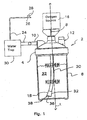
- Fig. 1 is a diagrammatic view showing an application for the bubble humidifier of the present invention
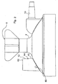
- Fig. 2 is an exploded diagrammatic perspective view of the cover for the bubble humidifier of Fig. 1 ;
- Fig. 3 is a diagrammatic cross-sectional view showing the pressure relief device incorporated within the cover of the bubble humidifier shown in its normally closed position;
- Fig. 4 is a diagrammatic cross-sectional view showing the pressure relief device incorporated within the cover of the bubble humidifier shown in its normally opened position with the slug being lifted from its seating engagement with the relief port to remove excess pressure from bubble humidifier;
- Fig. 5 is a diagrammatic exploded view of the slug incorporated within the pressure relief device of Fig. 3 ;
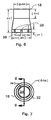
- Fig. 6 is a diagrammatic elevational view of the diffuser incorporated within the bubble humidifier for diffusing the oxygen prior to moisturizing the oxygen;
- Fig. 7 is a diagrammatic top plan view of the diffuser of Fig. 6 ;
- fig. 8 is a diagrammatic cross sectional view of the diffuser along section line 8-8 of Fig. 7 ;
- Fig. 9 is a diagrammatic end view of the diffuser 8 along section line 9-9 of Fig. 8 ;
- Fig. 10 is a diagrammatic perspective view of the diffuser of Fig. 6 .
- the bubble humidifier 2 generally comprises a removable cover 4 which sealingly engages with a humidifier base 6 of the bubble humidifier 2 either by a pair of mating screw threads (not shown) carried by the cover 4 and the humidifier base 6 or any other coupling arrangement which is conventional orwell known in the art.
- the humidifier base 6 is designed to hold a sufficient amount of liquid 22, i.e., water.
- the cover 4 has a centrally located oxygen inlet 8 and an oxygen outlet 10 as well as pressure relief device 12, the function of which will be discussed below in further detail.
- An outlet of the oxygen generator or source 16 is connected to the oxygen inlet 8 in a conventional manner, e.g., by a threaded wing nut coupling or the like for example.
- the oxygen source 16 generates a sufficient supply of oxygen and conveys the generated oxygen to the bubble humidifier 2.
- a diffuser 18 is located within the bubble humidifier 2 and a first end of a humidifier conduit 20 is connected to the oxygen inlet 8, to receive the oxygen conveyed by the flexible oxygen source conduit 14, while a second opposed end of the humidifier conduit 20 is connected to the diffuser 18.
- a first end of a moisturized oxygen supply conduit 24 is connected to the oxygen outlet 10 while an opposed second end of the moisturized oxygen supply conduit 24 is connected to an oxygen dispensing device or apparatus, such as a cannula 26.
- the cannula 26 has a pair of prongs 28 that are generally positioned in the nostrils of the patient to supply the moisturized oxygen to the patient.
- a conventional water trap 30 is positioned in the moisturized oxygen supply conduit 24, between the oxygen outlet 10 and the cannula 26, to remove any liquid conveyed along with the supplied and moisturized oxygen to the patient.
- a conventional oxygen supply system supplies a gas which has an oxygen content of between 93 percent to 95 percent with the balance of the supplied gas being nitrogen and other elements commonly found within air.
- the humidifier base 6 is typically sized to hold between 100 and 350 cc of liquid 22 to facilitate adding a sufficient amount of humidity to the oxygen being supplied, via the bubble humidifier 2, to the patient.
- the diffuser 18 generally comprises an exterior diffuser housing 32 which has an open first end which is sized and shaped to receive or mate with a remote end of the humidifier conduit 20 conveying the supply of oxygen to the diffuser 18 from the oxygen inlet 8.
- the remote end of the diffuser housing 32 generally tapers or flares outwardly and is closed or covered by a generally planar end wall or cap 36.
- the flared end cap 36 and the diffuser 18 may be formed separately from one another or are preferably integral with one another and together define a plurality of peripheral discharge passages 38, e.g., eight discharge passages formed therein.
- Each one of the discharge passages 38 is equally spaced about the periphery of the diffuser 18, e.g., located at an angle of 45° angle with respect to a longitudinal axis LD defined by the diffuser housing 32. Due to this arrangement, as the oxygen to be moisturized flows along the longitudinal axis LD of the diffuser housing 32, the oxygen impacts against the end cap 36 of the diffuser 18 and is forced and emitted out through one of the discharge passages 38 substantially at a right angle to the longitudinal axis L defined by the bubble humidifier 2.
- the longitudinal axis LD defined by the diffuser housing 32 is substantially coincident with the longitudinal axis L defined by the bubble humidifier 2.
- the oxygen emitted out through the discharge passages 38 has a tendency to form oxygen bubbles which are directed at and generally impact against the inner side wall of the humidifier base 6.
- the oxygen bubbles, emitted out through the discharge passages 38 tend to disperse within the liquid 22 as the oxygen bubbles permeate or filter up through the liquid 22 contained within the humidifier base 6 of the bubble humidifier 2.
- the relative high velocity of the oxygen bubbles, emitted out through the discharge passages, is reduced and partially absorbed as the oxygen flows through the liquid 22 toward the side wall of the humidifier base 6.
- the velocity reduction and energy absorption by the liquid 22 contained within the humidifier base 6 as well as the humidifier base side wall minimizes the amount of liquid 22 which has a tendency to be splashed or sprayed into the inlet of the moisturized oxygen supply conduit as the moisturized oxygen bubbles permeate upward through the liquid 22 and break the liquid surface.
- the pressure relief device 12 generally comprises a pressure relief housing 40 which has a relief port 42 formed in a base 58 of the pressure relief housing 40 which communicates directly with an interior compartment of the bubble diffuser 2.
- a movable slug 44 is accommodated within the pressure relief housing 40 and the slug 44 is axially movable along a longitudinal axis LP defined by the pressure relief housing 40.
- a downwardly facing surface of the slug 44 accommodates a conical shaped valve element 46 and the valve element 46 is sized and shaped to sealingly engage with the relief port 42 provided in the base 58 of the pressure relief housing 40. Due to the weight of the slug 44, e.g. about 8 grams or 0.285 ounce, the valve element 46 normally provides a gas tight seal with the relief port 42 provided in the base 58 of the pressure relief housing 40 to prevent the flow of any oxygen or liquid therethrough.
- An inwardly facing surface 48 of the pressure relief housing 40 can be provided with a first guidance member 50, such as an elongate rib which extends substantially along the longitudinal length of the pressure relief housing 40 while a complimentary guidance member 52, e.g., a mating slot, is provided along a side wall 53 of the slug 44.
- a first guidance member 50 such as an elongate rib which extends substantially along the longitudinal length of the pressure relief housing 40
- a complimentary guidance member 52 e.g., a mating slot
- the elongate rib and the mating slot engage with one another to facilitate axial sliding movement of the slug 44 along the longitudinal axis LP of the pressure relief housing 40 while preventing rotation or misalignment of the slug 44 within the pressure relief housing 40.
- This guidance mechanism 50, 52 also facilitates reseating of the valve element 46 with or over the relief port 42 should the slug 44 be biased away from engagement with the relief port 42 due to the generation of excess pressure within the bubble humidifier 2. and a further detailed description concerning such relief will follow below.
- the diameter of the slug 44 is slightly smaller in size than an internal diameter of the pressure relief housing 40 so that, in the event that the valve element 46 of the slug 44 is biased out of engagement with the relief port 42 of the pressure relief housing 40, the oxygen will be allowed to pass between the exterior surface of the slug 44 and the interior surface of the pressure relief housing 40 and exit via an exhaust port 54 formed in the pressure relief housing 40.
- the exhaust port 54 of the pressure relief device 12 is designed to generate a "whistling" sound, when a gas such as oxygen is exhausted therethrough, to indicate that the pressure relief device 12 is operating.
- the pressure inside the bubble humidifier 2 will decrease back to a normal operating pressure, e.g., between about 1-3 psi, and the slug 44 will have a tendency to be gradually lowered, by gravity within a few seconds or so, so that the valve element 46 again reseats and seals the relief port 42 of the pressure relief device 12.
- the valve element 46 is provided with an inclined conical surface 56 which forms an angle of about 15° with the longitudinal axis LP of the pressure relief device 12.
- valve element 46 has axial length of about 0.167 of an inch and a maximum diameter of about 0.145 of an inch, where the valve element 46 joins with the slug 44.
- the slug 44 preferably has a diameter of 0.464 +/- 0.001 of an inch and a height of about 0.34 of an inch.
- the relief port 42 provided in a base 58 of the pressuring relief device 12, has a diameter of about 0.062 of an inch while the pressure relief-housina 40 has an axial length of about 0.49 of an inch.
- At least one or a pair of opposed side exhaust ports 60 is/are provided in the side wall of the pressure relief housing 40.
- These side exhaust ports 60 have a diameter of about 0.10 of an inch and are both generally located in the side wall of the pressure relief device 12 at a position so as to communicate with and be covered by a side wall of the slug 44 when the slug 44 in its lowermost position with the valve element 46 sealing engaging with the relief port 42.
- the slug 44 will be biased or moved axially away from the base 58 of the pressure relief device 12 whereby the valve element 46 disengages from the relief port 42 provided in the base 58 of the pressure relief device 12.
- the side exhaust ports 60 directly communicate with the oxygen entering into the pressure relief device 12, via the relief port 42, and some of this oxygen can be vented through the side exhaust ports 60 directly to the atmosphere while a remainder of the oxygen is vented through the exhaust port 54 and generates the "whistling" sound.
- the exhaust side ports 60 also facilitate proper reseating of the valve element 46 of the slug 44 with the relief port 42, as soon as the medical personnel removes the kink, occlusion or other blockage contained in the moisturized oxygen supply conduit, since atmospheric air can enter through the side exhaust ports 60.
- the side exhaust ports 60 thus allow the pressure of the pressure relief device 12 to be quickly equalized and this pressure equalization facilitates proper seating of the valve element 46 with the relief port 42.
- a top wall 62 of the pressure relief device 12 is provided with a stop 64 which is located to abut against a rear surface 66 of the slug 44 when the slug 44 is moved to its fully open position.
- the stop 64 is a generally cylindrical member which is coincident with the longitudinal axis LP of the pressure relief device 12.
- the slug 44 is generally designed to relieve the pressure contained within the bubble humidifier 2 once the pressure contained therein is between 3 and 6 psi, for example.
- the inventors have discovered that conventional pressure relief valves for bubble humidifiers do not operate adequately at higher oxygen flow rates, i.e., oxygen flow rates of between about 6 to about 15 liters per minute or possibly higher.
- the relief port 42 provided in the base 58 of the pressure relief device 12 is only operational when excessive pressure is generated within the internal compartment of the bubble humidifier 2 and the improved the pressure relieve device 12 facilitates more accurate and reliable reseating of the valve element 46 with the relief port 42.
Landscapes
- Health & Medical Sciences (AREA)
- Pulmonology (AREA)
- Emergency Medicine (AREA)
- Engineering & Computer Science (AREA)
- Anesthesiology (AREA)
- Biomedical Technology (AREA)
- Heart & Thoracic Surgery (AREA)
- Hematology (AREA)
- Life Sciences & Earth Sciences (AREA)
- Animal Behavior & Ethology (AREA)
- General Health & Medical Sciences (AREA)
- Public Health (AREA)
- Veterinary Medicine (AREA)
- Otolaryngology (AREA)
- Air Humidification (AREA)
- Percussion Or Vibration Massage (AREA)
Abstract
Description
- FIELD OF THE INVENTION
- The present invention relates to improvements concerning a bubble humidifier used to humidify oxygen prior to dispensing the oxygen to a patient for medical purposes.
- BACKGROUND OF THE INVENTION
- Oxygen is supplied to patients for a variety of medical reasons. The conventional techniques for generating oxygen typically remove essentially all of the moisture from the generated oxygen so that the oxygen essentially has zero percent relative humidity. Prior to supplying the generated oxygen to a patient, the oxygen is generally sent through a bubble humidifier, or some other humidifying apparatus, where a suitable amount of humidity is added to the oxygen prior to supplying the same to the patient for a medical application.
- Standard humidifiers typically operate well for humidifying oxygen at an oxygen flow rate of from about 2 to 4 liters per minute. However, when the flow rate of the supplied oxygen is increased to 6 liters per minute or greater, the currently available bubble humidifiers do not work satisfactorily. In particular, the currently available bubble humidifiers have a tendency to jiggle and shake excessively due to the increase in the oxygen flow rate through the bubble humidifier. Such jiggling or shaking of the bubble humidifier, in turn, has a tendency to cause a valve component of the pressure relief device for the bubble humidifier to become unseated and vent a portion of the moisturized oxygen from the bubble humidifier to the surrounding environment rather than the supplying the same to the patient. Such venting of the supplied oxygen, via the pressure relief device, also causes the pressure relief device to emit a "whistling" sound. This sound generally indicates that at least a portion of the supplied moisturized oxygen is not being conveyed to the patient, e.g., the moisturized oxygen supply conduit for supplying the oxygen to the patient may have a kink therein or is somehow clogged or occluded. In response to the "whistling" sound, the medical personnel will then undertake corrective action, e.g., remove the kink or occlusion from the moisturized oxygen supply conduit.
- The conventional pressure relief devices work reasonably well for low oxygen flow rates, e.g., flow rates of 4 liters per minute or less. However, when the flow rate of the oxygen is increased to 6 liters per minute or greater, the conventional pressure relief devices have a tendency to malfunction as the valve of the pressure relief device does not always properly reseat itself to ensure that all of the supplied moisturized oxygen is again conveyed to the patient, via the moisturized oxygen supply conduit, rather than being vented to the surrounding environment
- The increased oxygen flow rate also has a tendency to cause the oxygen bubbles to coalesce and when the coalescing bubbles filter up through the liquid contained in the bubble humidifier and break the liquid surface. Upon breaking the liquid surface, liquid is splashed and sprayed toward the outlet of the bubble humidifier and into the moisturized oxygen supply conduit. This splashed and sprayed liquid, e.g., water, is then conveyed along with the moisturized oxygen toward a cannula connected at a remote end of the moisturized oxygen supply conduit, which supplies the moisturized oxygen into the nostrils of a patient. A water trap is installed, along the moisturized oxygen supply conduit, to remove small quantities of liquid from the moisturized oxygen. The conventional water traps work adequately for removing small amounts of water from the moisturized oxygen supply conduit, but the water trap can become quickly clogged if a targe quantity of liquid enters the moisturized oxygen supply conduit and is conveyed toward the patient.
United States Patent No.4,338,267 relates to an apparatus for humidifying medical gases. The apparatus comprises a pressure relief valve in association with the gas chamber. When the pressure within the gas chamber exceeds a predetermine level, the pressure relief valve opens to relieve the excess pressure and to simultaneously warn the operator than the predetermined pressure ievei has been exceeded. The pressure release valve is designed to be common with the gas inlet and the gas outlet. The unity between the valve and the gas inlet and outlet is a drawback due to the complexity of combining these three components while ensuring a proper fit and seal of these components. - SUMMARY OF THE INVENTION
- Wherefore, it is an object of the present invention to overcome the above mentioned shortcomings and drawbacks associated with the prior art bubble humidifiers.
- Another object of the present invention is to provide a bubble humidifier which is able to add a sufficient amount of moisture to oxygen for a medical application, while minimizing the amount of liquid, e.g., water, which enters into the moisturized oxygen supply conduit exiting from the bubble humidifier.
- A further object of the present invention is to provide a pressure relief device which reliably indicates when there is a blockage, kink or some occlusion in the moisturized oxygen supply conduit and also facilitates proper reseating of the valve element once the blockage, kink or occlusion is eliminated from the moisturized oxygen supply conduit.
- Yet another object of the present invention is to minimize the amount of liquid that enters into the moisturized oxygen supply conduit and must be removed by a water trap to minimize the associated maintenance required for use of the bubble humidifier.
- A still further object of the present invention is to provide a larger bubble humidifier surface area for the bubbles emitted by the diffuser to facilitate a greater and improved dispersion of the oxygen bubbles emitted by the.
- Yet another object of the present invention is to minimize the coalescence of the bubbles as they contact the side wall of the container so as to minimize the amount of turbulence of at the surface of the liquid as the oxygen bubbles migrate up through the liquid contained in the bubble humidifier during operation.
- The present invention also relates to a bubble humidifier for adding humidity to supplied oxygen, the bubble humidifier comprising: a humidifier base for containing a quantity of liquid; a cover for the humidifier base; the bubble humidifier having an oxygen inlet for supplying oxygen to the bubble humidifier and a moisturized oxygen outlet for connection to a moisturized oxygen supply conduit for supplying humidified oxygen to a patient, and the oxygen inlet being connected to a diffuser for diffusing the supplying oxygen within the bubble humidifier; the bubble humidifier having a pressure relieve device for relieving excess pressure generated within the bubble humidifier during operation thereof; and the bubble humidifierdefining a longitudinal axis; wherein the diffuser is arranged to discharge the oxygen from the diffuser substantially at an angle normal to the longitudinal axis of the bubble humidifier to minimize flow of liquid, contained within the humidifier base, from entering the moisturized oxygen outlet and being conveyed along the moisturized oxygen supply conduit during operation of the bubble humidifier.
- The present invention also relates to a method of adding humidity to supplied oxygen via the bubble humidifier, the method comprising the steps: providing a humidifier base containing a quantity of liquid; covering the humidifier base with a cover; providing the bubble humidifier with an oxygen inlet for supplying oxygen to the bubble humidifier, connecting an moisturized oxygen outlet to a moisturized oxygen supply conduit for supplying humidified oxygen to a patient, and connecting the oxygen inlet to a diffuser for diffusing the supplying oxygen within the liquid contained by the humidifier base; providing the bubble humidifier with a pressure relieve device for relieving excess pressure generated within the bubble humidifier during operation thereof; defining a longitudinal axis with the bubble humidifier; discharging, via a diffuser, the oxygen from the diffuser substantially at an angle normal to the longitudinal axis of the bubble humidifier to minimize flow of liquid, contained within the humidifier base, from entering the moisturized oxygen outlet and being conveyed along the moisturized oxygen supply conduit during operation of the bubble humidifier.
- BRIEF DESCRIPTION OF THE DRAWINGS
- The invention will now be described, by way of example, with reference to the accompanying drawings in which:
-
Fig. 1 is a diagrammatic view showing an application for the bubble humidifier of the present invention; -
Fig. 2 is an exploded diagrammatic perspective view of the cover for the bubble humidifier ofFig. 1 ; -
Fig. 3 is a diagrammatic cross-sectional view showing the pressure relief device incorporated within the cover of the bubble humidifier shown in its normally closed position; -
Fig. 4 is a diagrammatic cross-sectional view showing the pressure relief device incorporated within the cover of the bubble humidifier shown in its normally opened position with the slug being lifted from its seating engagement with the relief port to remove excess pressure from bubble humidifier; -
Fig. 5 is a diagrammatic exploded view of the slug incorporated within the pressure relief device ofFig. 3 ; -
Fig. 6 is a diagrammatic elevational view of the diffuser incorporated within the bubble humidifier for diffusing the oxygen prior to moisturizing the oxygen; -
Fig. 7 is a diagrammatic top plan view of the diffuser ofFig. 6 ; -
fig. 8 is a diagrammatic cross sectional view of the diffuser along section line 8-8 ofFig. 7 ; -
Fig. 9 is a diagrammatic end view of thediffuser 8 along section line 9-9 ofFig. 8 ; and -
Fig. 10 is a diagrammatic perspective view of the diffuser ofFig. 6 . - DETAILED DESCRIPTION OF THE INVENTION
- Turning now to
Fig. 1 , a brief description concerning the basic components of the present invention will now be discussed. As can be seen in this Figure, thebubble humidifier 2 generally comprises aremovable cover 4 which sealingly engages with ahumidifier base 6 of thebubble humidifier 2 either by a pair of mating screw threads (not shown) carried by thecover 4 and thehumidifier base 6 or any other coupling arrangement which is conventional orwell known in the art. Thehumidifier base 6 is designed to hold a sufficient amount ofliquid 22, i.e., water. Thecover 4 has a centrally locatedoxygen inlet 8 and anoxygen outlet 10 as well aspressure relief device 12, the function of which will be discussed below in further detail. An outlet of the oxygen generator orsource 16 is connected to theoxygen inlet 8 in a conventional manner, e.g., by a threaded wing nut coupling or the like for example. Theoxygen source 16 generates a sufficient supply of oxygen and conveys the generated oxygen to thebubble humidifier 2. Adiffuser 18 is located within thebubble humidifier 2 and a first end of ahumidifier conduit 20 is connected to theoxygen inlet 8, to receive the oxygen conveyed by the flexible oxygen source conduit 14, while a second opposed end of thehumidifier conduit 20 is connected to thediffuser 18. - A first end of a moisturized
oxygen supply conduit 24 is connected to theoxygen outlet 10 while an opposed second end of the moisturizedoxygen supply conduit 24 is connected to an oxygen dispensing device or apparatus, such as acannula 26. Thecannula 26 has a pair ofprongs 28 that are generally positioned in the nostrils of the patient to supply the moisturized oxygen to the patient. Aconventional water trap 30 is positioned in the moisturizedoxygen supply conduit 24, between theoxygen outlet 10 and thecannula 26, to remove any liquid conveyed along with the supplied and moisturized oxygen to the patient. - The important aspect concerning the engagement between the
removable cover 4 and thehumidifier base 6 is that those two components achieve a substantially gas and water tight seal is therebetween. A conventional oxygen supply system supplies a gas which has an oxygen content of between 93 percent to 95 percent with the balance of the supplied gas being nitrogen and other elements commonly found within air. Thehumidifier base 6 is typically sized to hold between 100 and 350 cc ofliquid 22 to facilitate adding a sufficient amount of humidity to the oxygen being supplied, via thebubble humidifier 2, to the patient. - As can be seen in
Figs. 6-10 , thediffuser 18 generally comprises anexterior diffuser housing 32 which has an open first end which is sized and shaped to receive or mate with a remote end of thehumidifier conduit 20 conveying the supply of oxygen to thediffuser 18 from theoxygen inlet 8. The remote end of thediffuser housing 32 generally tapers or flares outwardly and is closed or covered by a generally planar end wall orcap 36. Theflared end cap 36 and thediffuser 18 may be formed separately from one another or are preferably integral with one another and together define a plurality ofperipheral discharge passages 38, e.g., eight discharge passages formed therein. Each one of thedischarge passages 38 is equally spaced about the periphery of thediffuser 18, e.g., located at an angle of 45° angle with respect to a longitudinal axis LD defined by thediffuser housing 32. Due to this arrangement, as the oxygen to be moisturized flows along the longitudinal axis LD of thediffuser housing 32, the oxygen impacts against theend cap 36 of thediffuser 18 and is forced and emitted out through one of thedischarge passages 38 substantially at a right angle to the longitudinal axis L defined by thebubble humidifier 2. The longitudinal axis LD defined by thediffuser housing 32 is substantially coincident with the longitudinal axis L defined by thebubble humidifier 2. The oxygen emitted out through thedischarge passages 38 has a tendency to form oxygen bubbles which are directed at and generally impact against the inner side wall of thehumidifier base 6. The oxygen bubbles, emitted out through thedischarge passages 38, tend to disperse within the liquid 22 as the oxygen bubbles permeate or filter up through the liquid 22 contained within thehumidifier base 6 of thebubble humidifier 2. - The relative high velocity of the oxygen bubbles, emitted out through the discharge passages, is reduced and partially absorbed as the oxygen flows through the liquid 22 toward the side wall of the
humidifier base 6. The velocity reduction and energy absorption by the liquid 22 contained within thehumidifier base 6 as well as the humidifier base side wall, minimizes the amount ofliquid 22 which has a tendency to be splashed or sprayed into the inlet of the moisturized oxygen supply conduit as the moisturized oxygen bubbles permeate upward through the liquid 22 and break the liquid surface. - With reference now to
Figs. 3 through 5 , a detailed description concerning thepressure relief device 12 for use with theimproved bubble humidifier 2 of the present invention will now be provided. As can be seen in these drawings, thepressure relief device 12 generally comprises apressure relief housing 40 which has arelief port 42 formed in abase 58 of thepressure relief housing 40 which communicates directly with an interior compartment of thebubble diffuser 2. Amovable slug 44 is accommodated within thepressure relief housing 40 and theslug 44 is axially movable along a longitudinal axis LP defined by thepressure relief housing 40. A downwardly facing surface of theslug 44 accommodates a conical shapedvalve element 46 and thevalve element 46 is sized and shaped to sealingly engage with therelief port 42 provided in thebase 58 of thepressure relief housing 40. Due to the weight of theslug 44, e.g. about 8 grams or 0.285 ounce, thevalve element 46 normally provides a gas tight seal with therelief port 42 provided in thebase 58 of thepressure relief housing 40 to prevent the flow of any oxygen or liquid therethrough. - An inwardly facing
surface 48 of thepressure relief housing 40 can be provided with afirst guidance member 50, such as an elongate rib which extends substantially along the longitudinal length of thepressure relief housing 40 while acomplimentary guidance member 52, e.g., a mating slot, is provided along aside wall 53 of theslug 44. The elongate rib and the mating slot engage with one another to facilitate axial sliding movement of theslug 44 along the longitudinal axis LP of thepressure relief housing 40 while preventing rotation or misalignment of theslug 44 within thepressure relief housing 40. Thisguidance mechanism valve element 46 with or over therelief port 42 should theslug 44 be biased away from engagement with therelief port 42 due to the generation of excess pressure within thebubble humidifier 2. and a further detailed description concerning such relief will follow below. - The diameter of the
slug 44 is slightly smaller in size than an internal diameter of thepressure relief housing 40 so that, in the event that thevalve element 46 of theslug 44 is biased out of engagement with therelief port 42 of thepressure relief housing 40, the oxygen will be allowed to pass between the exterior surface of theslug 44 and the interior surface of thepressure relief housing 40 and exit via anexhaust port 54 formed in thepressure relief housing 40. Theexhaust port 54 of thepressure relief device 12 is designed to generate a "whistling" sound, when a gas such as oxygen is exhausted therethrough, to indicate that thepressure relief device 12 is operating. It is to be appreciated that when thepressure relief device 12 is operational, this indicates to the medical personnel that a kink or some sort of blockage or occlusion is contained somewhere along the moisturizedoxygen supply conduit 24. When a medical personnel detects a whistling sound emitted by thepressure relief device 12, the medical personnel will carefully examine the moisturizedoxygen supply conduit 24 and remove any kink contained therein or remove any occlusion or blockage within the moisturizedoxygen supply conduit 24 so that a continuous and uninterrupted supply of humidified oxygen is supplied to the patient. - Once the kink, occlusion or blockage is removed from the moisturized
oxygen supply conduit 24, the pressure inside thebubble humidifier 2 will decrease back to a normal operating pressure, e.g., between about 1-3 psi, and theslug 44 will have a tendency to be gradually lowered, by gravity within a few seconds or so, so that thevalve element 46 again reseats and seals therelief port 42 of thepressure relief device 12. To ensure that thevalve element 46 properly reseats itself each time over therelief port 42 thepressure relief device 12 is activated, thevalve element 46 is provided with an inclinedconical surface 56 which forms an angle of about 15° with the longitudinal axis LP of thepressure relief device 12. In addition, thevalve element 46 has axial length of about 0.167 of an inch and a maximum diameter of about 0.145 of an inch, where thevalve element 46 joins with theslug 44. Theslug 44 preferably has a diameter of 0.464 +/- 0.001 of an inch and a height of about 0.34 of an inch. Therelief port 42, provided in abase 58 of the pressuringrelief device 12, has a diameter of about 0.062 of an inch while the pressure relief-housina 40 has an axial length of about 0.49 of an inch. - To facilitate proper reseating of the
slug 44 within therelief port 42 provided in thebase 58 of thepressure relief device 12, at least one or a pair of opposedside exhaust ports 60 is/are provided in the side wall of thepressure relief housing 40. Theseside exhaust ports 60 have a diameter of about 0.10 of an inch and are both generally located in the side wall of thepressure relief device 12 at a position so as to communicate with and be covered by a side wall of theslug 44 when theslug 44 in its lowermost position with thevalve element 46 sealing engaging with therelief port 42. In the event that the pressure within thebubble humidifier 2 becomes excessive, e.g., in excess of 3 psi for example, theslug 44 will be biased or moved axially away from thebase 58 of thepressure relief device 12 whereby thevalve element 46 disengages from therelief port 42 provided in thebase 58 of thepressure relief device 12. Once this occurs, theside exhaust ports 60 directly communicate with the oxygen entering into thepressure relief device 12, via therelief port 42, and some of this oxygen can be vented through theside exhaust ports 60 directly to the atmosphere while a remainder of the oxygen is vented through theexhaust port 54 and generates the "whistling" sound. Theexhaust side ports 60 also facilitate proper reseating of thevalve element 46 of theslug 44 with therelief port 42, as soon as the medical personnel removes the kink, occlusion or other blockage contained in the moisturized oxygen supply conduit, since atmospheric air can enter through theside exhaust ports 60. Theside exhaust ports 60 thus allow the pressure of thepressure relief device 12 to be quickly equalized and this pressure equalization facilitates proper seating of thevalve element 46 with therelief port 42. - A
top wall 62 of thepressure relief device 12 is provided with astop 64 which is located to abut against a rear surface 66 of theslug 44 when theslug 44 is moved to its fully open position. Thestop 64 is a generally cylindrical member which is coincident with the longitudinal axis LP of thepressure relief device 12. - The
slug 44 is generally designed to relieve the pressure contained within thebubble humidifier 2 once the pressure contained therein is between 3 and 6 psi, for example. The inventors have discovered that conventional pressure relief valves for bubble humidifiers do not operate adequately at higher oxygen flow rates, i.e., oxygen flow rates of between about 6 to about 15 liters per minute or possibly higher. Therelief port 42 provided in thebase 58 of thepressure relief device 12 is only operational when excessive pressure is generated within the internal compartment of thebubble humidifier 2 and the improved the pressure relievedevice 12 facilitates more accurate and reliable reseating of thevalve element 46 with therelief port 42. - Since certain changes may be made in the above described improved bubble humidifier, diffuser and the pressure relief device, without departing from the scope of the invention herein involved, it is intended that all of the subject matter of the above description or shown in the accompanying drawings shall be interpreted merely as examples illustrating the inventive concept herein and shall not be construed as limiting the invention.
Claims (18)
- A bubble humidifier (2) for adding humidity to supplied oxygen, the bubble humidifier (2) comprising a humidifier base (6) for containing a quantity of liquid (22), a cover (4) for the humidifier base (6), the bubble humidifier (2) having an oxygen inlet (8) for supplying oxygen to the bubble humidifier (2) and a moisturized oxygen outlet (10) for connection to a moisturized oxygen supply conduit (24) for supplying humidified oxygen to a patient, and the oxygen inlet (8) being connected to a diffuser (18) for diffusing the supplied oxygen within the liquid (22) to be contained within the humidifier base (6), the bubble humidifier (2) having a pressure relief device (12) for relieving excess pressure generated within the bubble humidifier (2) during operation thereof; and the bubble humidifier (2) defining a longitudinal axis (L) and the diffuser (18) is arranged to discharge the oxygen from the diffuser (18) at an angle substantially normal to the longitudinal axis (L) of the bubble humidifier (2) to minimize the flow of the liquid (22), to be contained within the humidifier base (6), from entering the moisturized oxygen outlet (10) and being conveyed along the moisturized oxygen supply conduit (24) during operation of the bubble humidifier (2),
characterized by at least one side exhaust port (54) being provided in a. side wall of the pressure relief device (12), and the at least one side exhaust port (54) communicates with and is covered by a side wall of a slug (44) when the slug (44) sealing engages with a relief port (42), and when the excess pressure is generated within the bubble humidifier (2), the slug (44) is biased axially away from a base of the pressure relief device (12) whereby a valve element (46) of the slug (44) disengages from the relief port (42) and the at least one side exhaust port (54) directly communicates with the oxygen entering into the pressure relief device (12), via the relief port (42), and a portion of this oxygen is vented through the at least one side exhaust port (54) directly to atmosphere while a remainder of the oxygen, is vented through a second exhaust port (60). - The bubble humidifier (2) according to claim 1, characterized in that the bubble humidifier (2) is used in combination with an oxygen source (16) and an outlet of the oxygen source (16) is connected with the oxygen inlet (8) of the bubble humidifier (2); and the moisturized oxygen outlet (10) of the bubble humidifier (2) is connected, via a moisturized oxygen supply conduit (24), to an oxygen dispensing device for supplying the humidified oxygen to a patient.
- The bubble humidifier (2) according to claim 2, characterized in that the oxygen dispensing device is a cannula (26) and a water trap is provided in the moisturized oxygen supply conduit (24) for removing liquid conveyed along with the oxygen to minimize the amount of liquid conveyed to the cannula (26).
- The bubble humidifier (2) according to claim 2 or 3, characterized in that the a first end of a humidifier conduit (20) is connected to the oxygen inlet (8), to receive the oxygen conveyed by the oxygen source (16), while a second opposed end of the humidifier conduit (20) is connected to the diffuser (18).
- The bubble humidifier (2) according to any one of the preceding claims characterized in that the cover (4) engages with the humidifier base (6) in a manner such that a substantially gas and water tight seal is achieved between the cover (4) and the humidifier base (6).
- The bubble humidifier (2) according to any one of the preceding claims, characterized in that the humidifier base (6) is sized to hold between 100 and 350 cubic centimeters of the liquid (22) to facilitate adding a sufficient amount of humidity to the oxygen being supplied, via the bubble humidifier (2), to the patient.
- The bubble humidifier (2) according to any one of the preceding claims, characterized in that the humidifier (2) operates at an oxygen flow rate of between about 6 to 15 liters per minute.
- The bubble humidifier (2) according to any one of the preceding cairns, characterized in that the diffuser (18) comprises a diffuser housing (32) and a remote end of the diffuser housing (32) flares outwardly and is closed by an end wall (36), and a plurality of peripheral discharge passages (38) are formed in the remote end of the diffuser (18).
- The bubble humidifier (2) according to claim 8, characterized in that the peripheral discharge passages (38) are equally spaced about a periphery of the diffuser (18) and arranged so that the oxygen to be moisturized flows along a longitudinal axis (LD) of the diffuser housing (32), impacts against the end wall (36) and is emitted out through one of the peripheral discharge passages (38) substantially at a right angle to the longitudinal axis (L) defined by the bubble humidifier (2).
- The bubble humidifier (2) according to claim 8 or 9, characterized in that the oxygen, emitted out through the plurality of discharge passages (38), forms oxygen bubbles, and the formed oxygen bubbles disperse within the liquid (22) as the oxygen bubbles permeate and filter up through the liquid (22) contained with in the humidifier base (6) of the bubble humidifier (2).
- The bubble humidifier (2) according to any one of the preceding claims, characterized in that the pressure relief device (12) comprises a pressure relief housing (40) which has the relief port (42) formed in a base thereof which communicates directly with an interior compartment of the bubble diffuser (18), and the slug (44) is accommodated within the pressure relief housing (40), the slug (44.) normally seals the relief port (42) but is movable relative to the relief port (42) to relieve the excess pressure generated within the bubble humidifier (2).
- The bubble humidifier (2) according to claim 11, characterized in that the pressure relief device (12) defines a longitudinal axis (LP) and the slug (44) is movable along the longitudinal axis (LP) defined by the pressure relief device (12), and a downwardly facing surface of the slug (44) accommodates the valve element (46) which is conically shaped to sealingly engage with the relief port (42).
- The bubble humidifier (2) according to claim 11 or 12, characterized in that the slug (44) has a weight of about 0.285 ounces, and the valve element (46) normally provides a gas tight seal with the relief port (42) to prevent the flow of any oxygen or liquid therethrough.
- The bubble humidifier (2) according to any one of claim 11 to 13, characterized in that the pressure relief housing (40) is provided with a first guidance member (50) and the slug (44) has a complimentary guidance member (52), and the two guidance members (50, 52) facilitate reseating of the valve element (46) over the relief port (42) following separation of the slug (44) from the relief port (42).
- The bubble humidifier (2) according to any one of claims 11 to 14 , characterized in that the slug (44) has a diameter which is slightly smaller than an internal diameter of the pressure relief housing (40) so that, in the event that the valve element (46) is biased out of engagement with the relief port (42), oxygen will be allowed to pass between an exterior surface of the slug (44) and an interior surface of the pressure relief housing (40) and exit via an exhaust port (54) formed in the pressure relief housing (40).
- The bubble humidifier (2) according to claim 15, characterized in that the exhaust port (54) generates a sound, when oxygen is exhausted therethrough, to indicate that the pressure relief device (12) is operating.
- The bubble humidifier (2) according to any one of claims 12 to 16 , characterized in that the valve element (46) has an inclined conical surface which forms an angle of about 15° with the longitudinal axis (LP) of the pressure relief device (12).
- The bubble humidifier (2) according to any one of claims 12 to 17 ;
characterized in that a top wall (62) of the pressure relief device (12) is provided with a stop (64) which is located to abut against a rear surface of the slug (44) when the slug (44) is moved to a fully open position, and the stop (46) is generally a cylindrical member which is coincident with the longitudinal axis (L) of the pressure relief device (12).
Applications Claiming Priority (3)
| Application Number | Priority Date | Filing Date | Title |
|---|---|---|---|
| US151696 | 2002-05-17 | ||
| US10/151,696 US6786475B2 (en) | 2002-05-17 | 2002-05-17 | Bubble humidifier with improved diffuser and pressure relief device |
| PCT/US2003/015157 WO2003097224A1 (en) | 2002-05-17 | 2003-05-13 | Bubble humidifier with improved diffuser and pressure relief device |
Publications (3)
| Publication Number | Publication Date |
|---|---|
| EP1507582A1 EP1507582A1 (en) | 2005-02-23 |
| EP1507582A4 EP1507582A4 (en) | 2008-09-10 |
| EP1507582B1 true EP1507582B1 (en) | 2012-02-22 |
Family
ID=29419497
Family Applications (1)
| Application Number | Title | Priority Date | Filing Date |
|---|---|---|---|
| EP03728898A Expired - Lifetime EP1507582B1 (en) | 2002-05-17 | 2003-05-13 | Bubble humidifier with improved diffuser and pressure relief device |
Country Status (10)
| Country | Link |
|---|---|
| US (1) | US6786475B2 (en) |
| EP (1) | EP1507582B1 (en) |
| JP (1) | JP4593268B2 (en) |
| AT (1) | ATE546218T1 (en) |
| AU (1) | AU2003234557B2 (en) |
| CA (1) | CA2485790C (en) |
| DK (1) | DK1507582T3 (en) |
| ES (1) | ES2383087T3 (en) |
| PT (1) | PT1507582E (en) |
| WO (1) | WO2003097224A1 (en) |
Families Citing this family (21)
| Publication number | Priority date | Publication date | Assignee | Title |
|---|---|---|---|---|
| AU782579B2 (en) * | 1999-12-10 | 2005-08-11 | Vapotherm, Inc. | Apparatus and method for respiratory tract therapy |
| US7708013B2 (en) * | 2000-12-08 | 2010-05-04 | Vapotherm, Inc. | Apparatus and method for delivering water vapor to a gas |
| US7827981B2 (en) * | 2003-01-29 | 2010-11-09 | Vapotherm, Inc. | Method for reducing the work of breathing |
| US20050150491A1 (en) * | 2004-01-13 | 2005-07-14 | Yu-Yu Chen | Steam inhaler |
| US7302949B2 (en) * | 2004-12-03 | 2007-12-04 | Smiths Medical Asd, Inc. | High flow humidifier for delivering heated and humidified breathing gases |
| CN100430104C (en) * | 2005-11-18 | 2008-11-05 | 北京北辰亚奥科技有限公司 | A humidification bottle with separated outlet |
| KR101397207B1 (en) * | 2007-06-12 | 2014-05-20 | 삼성전자주식회사 | Method and apparatus for receiving/transmitting common control channels in a mobile communication system |
| US20090306528A1 (en) * | 2008-06-06 | 2009-12-10 | Salter Labs | Adaptive temperature sensor for breath monitoring device |
| JP2011522618A (en) | 2008-06-06 | 2011-08-04 | サルター ラブス | Temperature detector applicable to respiratory monitoring device |
| US20100168600A1 (en) * | 2008-06-06 | 2010-07-01 | Salter Labs | Support structure for airflow temperature sensor and the method of using the same |
| US20090306529A1 (en) * | 2008-06-06 | 2009-12-10 | Salter Labs | Adaptive temperature sensor for breath monitoring device |
| US20120018910A1 (en) * | 2010-07-26 | 2012-01-26 | Moreno Gil G | Apparatus to add gas from liquid state source to a dry carrier gas at low pressure |
| US8985560B2 (en) | 2011-06-09 | 2015-03-24 | FLO EZ Technologies | Oxygen humidifier |
| US8876087B1 (en) * | 2011-10-13 | 2014-11-04 | William M. Lake | Water tank system |
| KR101369803B1 (en) | 2012-12-04 | 2014-03-20 | 주식회사 옥시백 | Flowmeter with humidifier |
| KR101440581B1 (en) * | 2012-12-04 | 2014-09-17 | 주식회사 옥시백 | Flowmeter with humidifier |
| US8561970B1 (en) * | 2013-01-23 | 2013-10-22 | Brookstone Purchasing, Inc. | Aeration system |
| KR101685901B1 (en) * | 2016-07-15 | 2016-12-13 | 최연옥 | Portable air cleaner |
| EP3720534B1 (en) * | 2017-12-06 | 2023-04-19 | Fisher & Paykel Healthcare Limited | Humidifier |
| CN112007247B (en) * | 2019-05-28 | 2023-04-25 | 上海潓美医疗科技有限公司 | Wearable breathing circuit system and breathing apparatus having breathing circuit system |
| IL276649B2 (en) * | 2020-08-11 | 2025-11-01 | Sodastream Ind Ltd | Ventilator |
Family Cites Families (11)
| Publication number | Priority date | Publication date | Assignee | Title |
|---|---|---|---|---|
| US1333558A (en) * | 1918-10-28 | 1920-03-09 | Minor Edward Lynnwood | Fuel-economizer for engines |
| US2584450A (en) * | 1947-09-02 | 1952-02-05 | Univ Minnesota | Tracheotomy inhaler apparatus |
| US3395703A (en) * | 1965-10-22 | 1968-08-06 | Chemetron Corp | Nebulizer |
| GB1156073A (en) * | 1966-12-17 | 1969-06-25 | Draegerwerk Ag | An Evaporator for Anaesthetic. |
| GB1212147A (en) * | 1969-04-02 | 1970-11-11 | Stile Craft Mfg Inc | Audible relief valve |
| FR2084292A5 (en) * | 1970-03-06 | 1971-12-17 | Dresser Ind | |
| US3864440A (en) * | 1972-01-21 | 1975-02-04 | Respiratory Care | Humidifier and heater for delivered gas |
| US4338267A (en) | 1979-08-23 | 1982-07-06 | Becton, Dickinson And Company | Medical gas humidifier with audible pressure relief valve and method of use |
| JPS62139671A (en) * | 1985-12-13 | 1987-06-23 | 帝人株式会社 | Humidifier and oxygen enriched gas supply apparatus |
| US6202991B1 (en) * | 1999-02-03 | 2001-03-20 | Nicholas Edward Coniglio | Bubble humidifier with valve inlet for supplying liquid therein |
| JP2001029474A (en) * | 1999-07-21 | 2001-02-06 | Central Uni Co Ltd | Heated humidifier inhaler |
-
2002
- 2002-05-17 US US10/151,696 patent/US6786475B2/en not_active Expired - Lifetime
-
2003
- 2003-05-13 WO PCT/US2003/015157 patent/WO2003097224A1/en not_active Ceased
- 2003-05-13 DK DK03728898.2T patent/DK1507582T3/en active
- 2003-05-13 PT PT03728898T patent/PT1507582E/en unknown
- 2003-05-13 EP EP03728898A patent/EP1507582B1/en not_active Expired - Lifetime
- 2003-05-13 AU AU2003234557A patent/AU2003234557B2/en not_active Ceased
- 2003-05-13 JP JP2004504612A patent/JP4593268B2/en not_active Expired - Fee Related
- 2003-05-13 ES ES03728898T patent/ES2383087T3/en not_active Expired - Lifetime
- 2003-05-13 CA CA2485790A patent/CA2485790C/en not_active Expired - Fee Related
- 2003-05-13 AT AT03728898T patent/ATE546218T1/en active
Also Published As
| Publication number | Publication date |
|---|---|
| JP2005525855A (en) | 2005-09-02 |
| ATE546218T1 (en) | 2012-03-15 |
| DK1507582T3 (en) | 2012-06-11 |
| PT1507582E (en) | 2012-05-22 |
| AU2003234557A1 (en) | 2003-12-02 |
| ES2383087T3 (en) | 2012-06-18 |
| US20030214056A1 (en) | 2003-11-20 |
| US6786475B2 (en) | 2004-09-07 |
| AU2003234557B2 (en) | 2009-09-10 |
| CA2485790C (en) | 2011-04-05 |
| CA2485790A1 (en) | 2003-11-27 |
| JP4593268B2 (en) | 2010-12-08 |
| EP1507582A1 (en) | 2005-02-23 |
| WO2003097224A1 (en) | 2003-11-27 |
| EP1507582A4 (en) | 2008-09-10 |
Similar Documents
| Publication | Publication Date | Title |
|---|---|---|
| US6786475B2 (en) | Bubble humidifier with improved diffuser and pressure relief device | |
| JP2005525855A5 (en) | ||
| US6340023B2 (en) | Rebreather nebulizer device | |
| EP2656868A3 (en) | Breathing assistance apparatus | |
| CA2105315C (en) | Nebulizer | |
| CA2196717A1 (en) | Air Eliminator | |
| US6202991B1 (en) | Bubble humidifier with valve inlet for supplying liquid therein | |
| US4177945A (en) | Humidifier unit | |
| CN1444497A (en) | Pressure regulator for respirator system | |
| KR101944697B1 (en) | Oxygen breathing apparatus for emergency | |
| US3771721A (en) | Nebulizer | |
| JPS6014864A (en) | Gas removing apparatus | |
| CA2170188A1 (en) | Anesthesia Machine | |
| US20210387025A1 (en) | Integrated manifold system | |
| NO151139B (en) | APPARATUS FOR ADMINISTRATING ANESTHESIA GAS | |
| EP1927380A1 (en) | High expansion foam fire-extinguishing system | |
| EP0094757A2 (en) | Respirator | |
| WO2003000329A3 (en) | Flow regulator for aerosol drug delivery device and methods | |
| JPH07553A (en) | Regulator for built-in type breathing device | |
| US4338267A (en) | Medical gas humidifier with audible pressure relief valve and method of use | |
| US4590933A (en) | Static pressure automatic control device for closed circuit respirator | |
| CA1282809C (en) | Quick disconnect assembly | |
| JP3689484B2 (en) | Gas supply device and gas supply device | |
| CN223350751U (en) | Hyperbaric oxygen chamber oxygen mask with automatic oxygen storage and waste oxygen discharge | |
| AU2023234504A1 (en) | Breathing apparatus and a method of controlling the breathing apparatus |
Legal Events
| Date | Code | Title | Description |
|---|---|---|---|
| PUAI | Public reference made under article 153(3) epc to a published international application that has entered the european phase |
Free format text: ORIGINAL CODE: 0009012 |
|
| 17P | Request for examination filed |
Effective date: 20041206 |
|
| AK | Designated contracting states |
Kind code of ref document: A1 Designated state(s): AT BE BG CH CY CZ DE DK EE ES FI FR GB GR HU IE IT LI LU MC NL PT RO SE SI SK TR |
|
| AX | Request for extension of the european patent |
Extension state: AL LT LV MK |
|
| RIN1 | Information on inventor provided before grant (corrected) |
Inventor name: CRANDALL, BARRY Inventor name: SALTER, PETER, W. Inventor name: DAVENPORT, JAMES, M. Inventor name: CURTI, JAMES, N. |
|
| DAX | Request for extension of the european patent (deleted) | ||
| A4 | Supplementary search report drawn up and despatched |
Effective date: 20080808 |
|
| RIC1 | Information provided on ipc code assigned before grant |
Ipc: A61M 16/20 20060101ALI20080804BHEP Ipc: B01F 3/04 20060101AFI20031203BHEP |
|
| 17Q | First examination report despatched |
Effective date: 20101018 |
|
| RTI1 | Title (correction) |
Free format text: BUBBLE HUMIDIFIER WITH IMPROVED DIFFUSER AND PRESSURE RELIEF DEVICE |
|
| GRAP | Despatch of communication of intention to grant a patent |
Free format text: ORIGINAL CODE: EPIDOSNIGR1 |
|
| GRAS | Grant fee paid |
Free format text: ORIGINAL CODE: EPIDOSNIGR3 |
|
| GRAA | (expected) grant |
Free format text: ORIGINAL CODE: 0009210 |
|
| AK | Designated contracting states |
Kind code of ref document: B1 Designated state(s): AT BE BG CH CY CZ DE DK EE ES FI FR GB GR HU IE IT LI LU MC NL PT RO SE SI SK TR |
|
| REG | Reference to a national code |
Ref country code: GB Ref legal event code: FG4D |
|
| REG | Reference to a national code |
Ref country code: CH Ref legal event code: EP |
|
| REG | Reference to a national code |
Ref country code: AT Ref legal event code: REF Ref document number: 546218 Country of ref document: AT Kind code of ref document: T Effective date: 20120315 |
|
| REG | Reference to a national code |
Ref country code: IE Ref legal event code: FG4D |
|
| REG | Reference to a national code |
Ref country code: DE Ref legal event code: R096 Ref document number: 60340066 Country of ref document: DE Effective date: 20120419 |
|
| REG | Reference to a national code |
Ref country code: PT Ref legal event code: SC4A Free format text: AVAILABILITY OF NATIONAL TRANSLATION Effective date: 20120510 |
|
| REG | Reference to a national code |
Ref country code: SE Ref legal event code: TRGR |
|
| REG | Reference to a national code |
Ref country code: NL Ref legal event code: T3 |
|
| REG | Reference to a national code |
Ref country code: DK Ref legal event code: T3 |
|
| REG | Reference to a national code |
Ref country code: ES Ref legal event code: FG2A Ref document number: 2383087 Country of ref document: ES Kind code of ref document: T3 Effective date: 20120618 |
|
| REG | Reference to a national code |
Ref country code: GR Ref legal event code: EP Ref document number: 20120401157 Country of ref document: GR Effective date: 20120614 |
|
| PGFP | Annual fee paid to national office [announced via postgrant information from national office to epo] |
Ref country code: DE Payment date: 20120602 Year of fee payment: 10 Ref country code: LU Payment date: 20120524 Year of fee payment: 10 Ref country code: NL Payment date: 20120530 Year of fee payment: 10 Ref country code: DK Payment date: 20120515 Year of fee payment: 10 Ref country code: IE Payment date: 20120430 Year of fee payment: 10 Ref country code: MC Payment date: 20120622 Year of fee payment: 10 |
|
| REG | Reference to a national code |
Ref country code: CH Ref legal event code: NV Representative=s name: CABINET ROLAND NITHARDT CONSEILS EN PROPRIETE INDU |
|
| PGFP | Annual fee paid to national office [announced via postgrant information from national office to epo] |
Ref country code: BE Payment date: 20120522 Year of fee payment: 10 Ref country code: GR Payment date: 20120525 Year of fee payment: 10 Ref country code: SE Payment date: 20120515 Year of fee payment: 10 Ref country code: FR Payment date: 20120622 Year of fee payment: 10 Ref country code: FI Payment date: 20120516 Year of fee payment: 10 Ref country code: GB Payment date: 20120618 Year of fee payment: 10 |
|
| PG25 | Lapsed in a contracting state [announced via postgrant information from national office to epo] |
Ref country code: CY Free format text: LAPSE BECAUSE OF FAILURE TO SUBMIT A TRANSLATION OF THE DESCRIPTION OR TO PAY THE FEE WITHIN THE PRESCRIBED TIME-LIMIT Effective date: 20120222 |
|
| PGFP | Annual fee paid to national office [announced via postgrant information from national office to epo] |
Ref country code: IT Payment date: 20120529 Year of fee payment: 10 |
|
| PG25 | Lapsed in a contracting state [announced via postgrant information from national office to epo] |
Ref country code: EE Free format text: LAPSE BECAUSE OF FAILURE TO SUBMIT A TRANSLATION OF THE DESCRIPTION OR TO PAY THE FEE WITHIN THE PRESCRIBED TIME-LIMIT Effective date: 20120222 Ref country code: SI Free format text: LAPSE BECAUSE OF FAILURE TO SUBMIT A TRANSLATION OF THE DESCRIPTION OR TO PAY THE FEE WITHIN THE PRESCRIBED TIME-LIMIT Effective date: 20120222 Ref country code: CZ Free format text: LAPSE BECAUSE OF FAILURE TO SUBMIT A TRANSLATION OF THE DESCRIPTION OR TO PAY THE FEE WITHIN THE PRESCRIBED TIME-LIMIT Effective date: 20120222 Ref country code: RO Free format text: LAPSE BECAUSE OF FAILURE TO SUBMIT A TRANSLATION OF THE DESCRIPTION OR TO PAY THE FEE WITHIN THE PRESCRIBED TIME-LIMIT Effective date: 20120222 |
|
| PG25 | Lapsed in a contracting state [announced via postgrant information from national office to epo] |
Ref country code: SK Free format text: LAPSE BECAUSE OF FAILURE TO SUBMIT A TRANSLATION OF THE DESCRIPTION OR TO PAY THE FEE WITHIN THE PRESCRIBED TIME-LIMIT Effective date: 20120222 |
|
| PLBE | No opposition filed within time limit |
Free format text: ORIGINAL CODE: 0009261 |
|
| STAA | Information on the status of an ep patent application or granted ep patent |
Free format text: STATUS: NO OPPOSITION FILED WITHIN TIME LIMIT |
|
| PGFP | Annual fee paid to national office [announced via postgrant information from national office to epo] |
Ref country code: ES Payment date: 20120514 Year of fee payment: 10 |
|
| 26N | No opposition filed |
Effective date: 20121123 |
|
| PGFP | Annual fee paid to national office [announced via postgrant information from national office to epo] |
Ref country code: PT Payment date: 20120517 Year of fee payment: 10 |
|
| REG | Reference to a national code |
Ref country code: DE Ref legal event code: R097 Ref document number: 60340066 Country of ref document: DE Effective date: 20121123 |
|
| PGFP | Annual fee paid to national office [announced via postgrant information from national office to epo] |
Ref country code: AT Payment date: 20120531 Year of fee payment: 10 |
|
| PG25 | Lapsed in a contracting state [announced via postgrant information from national office to epo] |
Ref country code: BG Free format text: LAPSE BECAUSE OF FAILURE TO SUBMIT A TRANSLATION OF THE DESCRIPTION OR TO PAY THE FEE WITHIN THE PRESCRIBED TIME-LIMIT Effective date: 20120522 |
|
| REG | Reference to a national code |
Ref country code: NL Ref legal event code: V1 Effective date: 20131201 |
|
| PG25 | Lapsed in a contracting state [announced via postgrant information from national office to epo] |
Ref country code: MC Free format text: LAPSE BECAUSE OF NON-PAYMENT OF DUE FEES Effective date: 20130531 |
|
| REG | Reference to a national code |
Ref country code: CH Ref legal event code: PL |
|
| REG | Reference to a national code |
Ref country code: SE Ref legal event code: EUG |
|
| REG | Reference to a national code |
Ref country code: AT Ref legal event code: MM01 Ref document number: 546218 Country of ref document: AT Kind code of ref document: T Effective date: 20130531 |
|
| GBPC | Gb: european patent ceased through non-payment of renewal fee |
Effective date: 20130513 |
|
| PG25 | Lapsed in a contracting state [announced via postgrant information from national office to epo] |
Ref country code: SE Free format text: LAPSE BECAUSE OF NON-PAYMENT OF DUE FEES Effective date: 20130514 Ref country code: AT Free format text: LAPSE BECAUSE OF NON-PAYMENT OF DUE FEES Effective date: 20130531 Ref country code: DE Free format text: LAPSE BECAUSE OF NON-PAYMENT OF DUE FEES Effective date: 20131203 Ref country code: LI Free format text: LAPSE BECAUSE OF NON-PAYMENT OF DUE FEES Effective date: 20130531 Ref country code: CH Free format text: LAPSE BECAUSE OF NON-PAYMENT OF DUE FEES Effective date: 20130531 |
|
| REG | Reference to a national code |
Ref country code: GR Ref legal event code: ML Ref document number: 20120401157 Country of ref document: GR Effective date: 20131204 |
|
| REG | Reference to a national code |
Ref country code: DK Ref legal event code: EBP Effective date: 20130531 |
|
| REG | Reference to a national code |
Ref country code: PT Ref legal event code: MM4A Free format text: LAPSE DUE TO NON-PAYMENT OF FEES Effective date: 20140213 |
|
| REG | Reference to a national code |
Ref country code: IE Ref legal event code: MM4A |
|
| REG | Reference to a national code |
Ref country code: DE Ref legal event code: R119 Ref document number: 60340066 Country of ref document: DE Effective date: 20131203 |
|
| PG25 | Lapsed in a contracting state [announced via postgrant information from national office to epo] |
Ref country code: IT Free format text: LAPSE BECAUSE OF NON-PAYMENT OF DUE FEES Effective date: 20130513 Ref country code: GR Free format text: LAPSE BECAUSE OF NON-PAYMENT OF DUE FEES Effective date: 20131204 Ref country code: FI Free format text: LAPSE BECAUSE OF NON-PAYMENT OF DUE FEES Effective date: 20130513 Ref country code: NL Free format text: LAPSE BECAUSE OF NON-PAYMENT OF DUE FEES Effective date: 20131201 |
|
| REG | Reference to a national code |
Ref country code: FR Ref legal event code: ST Effective date: 20140131 |
|
| PG25 | Lapsed in a contracting state [announced via postgrant information from national office to epo] |
Ref country code: DK Free format text: LAPSE BECAUSE OF NON-PAYMENT OF DUE FEES Effective date: 20130531 Ref country code: IE Free format text: LAPSE BECAUSE OF NON-PAYMENT OF DUE FEES Effective date: 20130513 Ref country code: GB Free format text: LAPSE BECAUSE OF NON-PAYMENT OF DUE FEES Effective date: 20130513 Ref country code: TR Free format text: LAPSE BECAUSE OF FAILURE TO SUBMIT A TRANSLATION OF THE DESCRIPTION OR TO PAY THE FEE WITHIN THE PRESCRIBED TIME-LIMIT Effective date: 20120222 |
|
| PG25 | Lapsed in a contracting state [announced via postgrant information from national office to epo] |
Ref country code: FR Free format text: LAPSE BECAUSE OF NON-PAYMENT OF DUE FEES Effective date: 20130531 |
|
| REG | Reference to a national code |
Ref country code: ES Ref legal event code: FD2A Effective date: 20140606 |
|
| PG25 | Lapsed in a contracting state [announced via postgrant information from national office to epo] |
Ref country code: PT Free format text: LAPSE BECAUSE OF NON-PAYMENT OF DUE FEES Effective date: 20140213 |
|
| PG25 | Lapsed in a contracting state [announced via postgrant information from national office to epo] |
Ref country code: HU Free format text: LAPSE BECAUSE OF FAILURE TO SUBMIT A TRANSLATION OF THE DESCRIPTION OR TO PAY THE FEE WITHIN THE PRESCRIBED TIME-LIMIT Effective date: 20030513 |
|
| PG25 | Lapsed in a contracting state [announced via postgrant information from national office to epo] |
Ref country code: ES Free format text: LAPSE BECAUSE OF NON-PAYMENT OF DUE FEES Effective date: 20130514 |
|
| PG25 | Lapsed in a contracting state [announced via postgrant information from national office to epo] |
Ref country code: LU Free format text: LAPSE BECAUSE OF NON-PAYMENT OF DUE FEES Effective date: 20130513 |
|
| PG25 | Lapsed in a contracting state [announced via postgrant information from national office to epo] |
Ref country code: BE Free format text: THE PATENT HAS BEEN ANNULLED BY A DECISION OF A NATIONAL AUTHORITY Effective date: 20120222 |