EP1507428A1 - Generating a code mask based on geographical coordinate values - Google Patents
Generating a code mask based on geographical coordinate values Download PDFInfo
- Publication number
- EP1507428A1 EP1507428A1 EP04254507A EP04254507A EP1507428A1 EP 1507428 A1 EP1507428 A1 EP 1507428A1 EP 04254507 A EP04254507 A EP 04254507A EP 04254507 A EP04254507 A EP 04254507A EP 1507428 A1 EP1507428 A1 EP 1507428A1
- Authority
- EP
- European Patent Office
- Prior art keywords
- value
- base station
- longitudinal
- latitude
- code mask
- Prior art date
- Legal status (The legal status is an assumption and is not a legal conclusion. Google has not performed a legal analysis and makes no representation as to the accuracy of the status listed.)
- Withdrawn
Links
- 238000000034 method Methods 0.000 claims abstract description 30
- 230000004913 activation Effects 0.000 claims description 5
- 230000004044 response Effects 0.000 claims description 4
- 238000004891 communication Methods 0.000 description 32
- 230000005540 biological transmission Effects 0.000 description 15
- 210000004027 cell Anatomy 0.000 description 9
- 230000007423 decrease Effects 0.000 description 8
- 238000010586 diagram Methods 0.000 description 7
- 230000015654 memory Effects 0.000 description 7
- 230000008901 benefit Effects 0.000 description 5
- 230000006870 function Effects 0.000 description 4
- 238000006243 chemical reaction Methods 0.000 description 3
- 238000012986 modification Methods 0.000 description 3
- 230000004048 modification Effects 0.000 description 3
- 230000008569 process Effects 0.000 description 3
- 238000011161 development Methods 0.000 description 2
- 238000005516 engineering process Methods 0.000 description 2
- 230000002452 interceptive effect Effects 0.000 description 2
- 238000012545 processing Methods 0.000 description 2
- 238000001228 spectrum Methods 0.000 description 2
- 230000009471 action Effects 0.000 description 1
- 238000013459 approach Methods 0.000 description 1
- 238000013475 authorization Methods 0.000 description 1
- 210000004271 bone marrow stromal cell Anatomy 0.000 description 1
- 230000001413 cellular effect Effects 0.000 description 1
- 230000008859 change Effects 0.000 description 1
- 238000010276 construction Methods 0.000 description 1
- 238000013461 design Methods 0.000 description 1
- 230000000694 effects Effects 0.000 description 1
- 230000006872 improvement Effects 0.000 description 1
- 238000007726 management method Methods 0.000 description 1
- 230000003287 optical effect Effects 0.000 description 1
- 230000010076 replication Effects 0.000 description 1
- 239000004065 semiconductor Substances 0.000 description 1
- 238000000638 solvent extraction Methods 0.000 description 1
- 230000003068 static effect Effects 0.000 description 1
Images



Classifications
-
- H—ELECTRICITY
- H04—ELECTRIC COMMUNICATION TECHNIQUE
- H04W—WIRELESS COMMUNICATION NETWORKS
- H04W16/00—Network planning, e.g. coverage or traffic planning tools; Network deployment, e.g. resource partitioning or cells structures
-
- H—ELECTRICITY
- H04—ELECTRIC COMMUNICATION TECHNIQUE
- H04W—WIRELESS COMMUNICATION NETWORKS
- H04W88/00—Devices specially adapted for wireless communication networks, e.g. terminals, base stations or access point devices
- H04W88/08—Access point devices
Definitions
- This invention relates generally to a communications system, and, more particularly, to generating a code mask based on geographical coordinate values.
- Figure 1 illustrates a portion of a geographic area in which wireless services are provided by a first service provider having a first network of cells 10 and a second service provider having a second network of cells 20.
- Each of the cells in the first and second network of cells 10 and 20 represent a coverage area for a corresponding base station in the network run by the respective service provider.
- a base station generally provides wireless communication services for mobile stations 12 within its coverage area.
- the communication between a base station and a mobile station 12 has great potential for interfering with the communication between another base station and another mobile station 12.
- This potential interference exists for base stations in the same network as well as between base stations in different networks.
- communication between a single base station and two different mobile stations 12 has the potential for interfering with one another.
- wireless communication systems such as Code Division Multiple Access 2000 (CDMA 2000) wireless systems use codes to differentiate transmissions.
- base stations BSs use codes generated from different offset values to differentiate between transmissions by different base stations.
- a base station BS uses codes to differentiate between different traffic channels assigned to mobile stations 12 by the base station BS.
- each service provider assigns an identifier BS_ID to the base stations to uniquely identify each base station in the network.
- a base station identifier BS_ID does not necessarily uniquely identify base stations in different networks.
- a base station codes its transmission based on a different offset such as the pseudoNoise (PN) offset in CDMA 2000.
- the PN offset is a 9-bit string that differentiates one base station BS from its neighboring base stations even when those base stations are in different networks.
- base stations from different networks may be neighboring base stations. While Figure 1 illustrates neighboring base stations as having coverage areas that are adjacent or near one another (e.g.
- the mobile station 12 obtains the PN offset from the base station to decode the transmissions from the base station and differentiate the transmission of one base station from another base station.
- the mobile station 12 obtains the PN offset as well as the base station identifier BS_ID from a message broadcast by the base station over a forward control channel.
- the base station uses codes to differentiate one traffic channel transmission from another traffic channel transmission.
- CDMA 2000 a different Walsh code is used to code each traffic channel of a base station.
- the Walsh code assigned to a traffic channel between the base station and a mobile station 12 is communicated to the mobile station 12 in a message over a forward control channel.
- the mobile station 12 decodes the transmission over the traffic channel and differentiates one traffic channel from another using the Walsh code.
- Codes are also used to differentiate reverse link transmissions (mobile station to base station) over traffic channels.
- the code used by a mobile station to code and differentiate traffic channel transmissions is referred to as a code mask.
- the code mask is referred to as the long code mask, and two types of long code masks are known: private and public.
- the public long code mask (PLCM) is typically formed using the electronic serial number (ESN) of the mobile station 12.
- ESN electronic serial number
- the PLCM in a CDMA 2000 system is 42-bits long; however, other long code mask sizes exist.
- the PLCM includes a plurality of bits for indicating the type of the long code mask (private or public), along with a 32-bit ESN of the mobile station 12. The 32-bit ESN is often considered the variable portion of the PLCM.
- a CDMA 2000 system also provides that the base station BS may assign a PLCM of its choosing to a mobile station 12 during a call activation (e.g. , call origination or call delivery).
- a call activation e.g. , call origination or call delivery
- BSAPLCM base station-assigned PLCM proposal
- all of the base stations use only one fixed format that supports all cell sizes, both large and small.
- the PLCM is formed of 42-bits, where the first 3 bits are utilized to distinguish between private/public code masks and to differentiate between the MEID generated PLCM and BS-Assigned PLCM.
- the remaining 39 bits of the PLCM are associated with three different components or fields - latitude (11 bits), longitude (11 bits), and a mobile station ID (MS_ID) (17 bits).
- the "longitude” and the “latitude” fields respectively contain a longitudinal value and a latitudinal value that represent the position of the base station. These values are expressed in units of "x" seconds, and are converted to an 11-bit number. The conversion to an 11-bit number is described in greater detail below.
- the mobile server ID field is a 17-bit field that is assigned by the base station to uniquely identify the mobile units 12. The longitude, latitude, and mobile server ID fields collectively make up the remaining 39 bits of the PLCM.
- the BSAPLCM proposal suggests that a given base station can be identified to a precision of substantially 0.25 seconds if 22-bit and 23-bit values are used to respectively represent the latitude and the longitude information associated with that base station. However, using a combined 44-bit value to represent the latitude and longitude information is not feasible because of the restriction imposed by the 42-bit long PLCM value.
- the proposal suggests using, for example, 11 bits to represent the latitude value and 11 bits to represent the longitude value of a base station, as shown in Figure 2.
- the BSAPLCM proposal arrives at the 11-bit longitude and latitude values by right shifting the corresponding 23-bit longitude and 22-bit latitude values by 5 bits and then converting the remaining bits to 11 bits using a MOD operation.
- the BSAPLCM proposal suggests that problems of multiple base stations that are located in close proximity (e.g., 0.15 miles) to each other, and thus have the same 11-bit longitude and latitude value, can be alleviated by partitioning the mobile station IDs (see Figure 2) among these base stations.
- partitioning the mobile station IDs see Figure 2 among these base stations.
- the rationale is that the mobile station IDs will be unique to each user. This approach involves some manual intervention by the service provider.
- the BSAPLCM proposal suffers from at least one shortcoming in that its calculations for the reusable distance (e.g., ⁇ 314 miles) are based upon conditions on or about the Earth's equator. That is, the proposal does not take into account the fact that the distance between longitudinal lines decrease as one moves away from the equator. As the distance between the longitudinal lines decrease, the reusable distance similarly decreases. A reduced reusable distance, however, is undesirable because the potential for collisions is greater. That is, as the reusable distance decreases, it becomes more likely that a mobile station 12 may obtain a PLCM in a first region and then travel the reusable distance to a second region where the same PLCM has been assigned to another mobile station 12. Accordingly, an improved way of generating PLCMs is desired to reduce the potential of collisions.
- the reusable distance e.g., ⁇ 314 miles
- the present invention is directed to overcoming, or at least reducing, the effects of, one or more of the problems set forth above.
- a method comprises defining a geographical position of a base station by a first coordinate value and a second coordinate value; modifying the first coordinate value based on the second coordinate value; and generating an identifier based on at least the modified first coordinate value.
- an apparatus for generating code masks that are associated with a base station that is definable by a latitudinal value and a longitudinal value.
- the apparatus comprises a storage unit having a plurality of code masks stored therein, wherein the code masks are generated by modifying the longitudinal value based on the latitudinal value.
- the apparatus further comprises a control unit communicatively coupled to the storage unit, the control unit adapted to assign at least one of the plurality of stored code masks to a mobile unit in response to detecting a call activation.
- a system in one embodiment, includes a mobile unit and a base station that is definable by a latitudinal value and a longitudinal value.
- the base station includes access to a plurality of code masks, wherein the code masks are generated by modifying the longitudinal value based on the latitudinal value, and wherein the base station is adapted to assign at least one of the plurality of the code masks to the mobile unit in response to detecting a call activation.
- a method in one embodiment, includes receiving a code mask associated with a base station that is definable by a latitudinal value and a longitudinal value, wherein the received code mask is generated by modifying the longitudinal value based on the latitudinal value.
- the method further comprises coding information using the received code mask.
- the communications system 100 of Figure 1 is a Code Division Multiple Access (CDMA) system, although it should be understood that the present invention may be applicable to other systems that support voice and/or data communication.
- CDMA Code Division Multiple Access
- a CDMA system is a "spread spectrum" technology, allowing many users to occupy the same time and frequency allocations in a given band/space. As its name implies, a CDMA system assigns unique codes to each communication to differentiate it from others in the same spectrum.
- a CDMA system includes second generation (2G) and third generation (3G) services.
- CDMA2000 represents a family of technologies that includes CDMA2000-1X and CDMA2000-1xEV).
- the communications system 100 of Figure 1 includes a mobile services switching center (MSC) 110 that allows one or more mobile units 120 to communicate with a Public Switched Telephone Network (PSTN) 150 and/or a data network 155, such as the Internet, through one or more base stations (BTS) 130.
- the mobile services switching center 110 of Figure 1 generally provides replication, communications, runtime, and system management services.
- the mobile services switching center 110 may also handle call processing functions, such as setting and terminating a call path.
- the mobile unit 120 may include one of a variety of devices, including cellular phones, personal digital assistants (PDAs), laptops, digital pagers, wireless cards, and any other device capable of accessing the networks 150, 155.
- PDAs personal digital assistants
- laptops digital pagers
- wireless cards and any other device capable of accessing the networks 150, 155.
- the plurality of base stations 130 may be distributed within an area to be serviced by the system 100.
- Various users within the area, fixed or mobile, may then access the system 100 and, thus, other interconnected telecommunications systems, via one or more of the base stations 130.
- a mobile user maintains communications with the system 100 as he/she passes through an area by communicating with one and then another base station 130, as he/she moves.
- the user may communicate with the closest base station 130, the base station 130 with the strongest signal, the base station 130 with a capacity sufficient to accept communications, etc .
- the base stations 130 include a code mask (CM) manager 160 that, as described in greater detail below, manages (e.g. , creates, assigns, tracks) code masks.
- CM code mask
- the code mask manager 160 specifically manages public long code masks (PLCMs).
- the code mask manager 160 may be implemented in software, hardware, or a combination thereof.
- an improved scheme for determining and assigning PLCMs to facilitate communications with the mobile units 120 in a manner that reduces the potential for collisions.
- the PLCMs are generated in accordance with the format shown in Figure 2.
- the CM manager 160 in calculating a PLCM, takes into account the fact that the distance between the longitude lines decrease as one moves away from the equator.
- the PLCMs are generated by adjusting a value associated with the longitude of a base station 130 based on the latitude of that base station 130. In this manner, the potential for collisions is reduced.
- the latitudinal value and the longitudinal value associated with a base station 130 can be calculated in one of a variety of well-known techniques known in the art, and, as such, are not described in detail herein.
- the communications system 100 also allows for soft and hard handovers. In instances when users change between different service networks, a hard handoff is required.
- a mobile unit 120 is assigned a new PLCM on a hard handoff, where the new PLCM will be based on the coordinates of the target base station 130. Assigning a new PLCM to the mobile station 120 on a hard handoff reduces the potential for collisions.
- the configuration of the communications system 100 of Figure 1 is exemplary in nature, and that fewer, additional, or different components may be employed in other embodiments of the communications system 100 without deviating from the spirit and scope of the invention.
- one or more routers may be interspersed between the MSC 110 and the bases stations 130.
- the communications system 100 may include an Authentication, Authorization, and Accounting (AAA) server (not shown).
- AAA Authentication, Authorization, and Accounting
- some or all portions of the CM manager 160 may be implemented in the MSC 110.
- other modifications may be made to the communications system 100 consistent with the spirit and scope of the present invention.
- the base station 130 includes a control unit 410 that is communicatively coupled to a storage unit 420 and is capable of executing one or more software instructions stored in the form of a program in the storage unit 420.
- the base station 130 includes the CM manager 160, which in the illustrated embodiment is implemented in software and is storable in the storage unit 420.
- the CM manager 160 includes a generating module 140 and an assigning and tracking module 440.
- the generating module 430 generally calculates the desired PLCMs for communications with the mobile unit 120.
- the base station 130 because the base station 130 includes the generating module 430, the base station 130 is capable of generating PLCMs on an as-needed basis.
- a pool 450 of PLCMs may be created in advance and pre-stored in the base station 130 for subsequent use.
- the pre-stored PLCMs may be created using the same scheme (described below) that is employed by the generating module 430 to generate the PLCMs.
- the PLCMs in the pool 450 can be reusable.
- the base station 130 that originally assigned the PLCM to the mobile unit 120 can release that PLCM (into the pool 450) so that it is available for reuse.
- the generating module 430 may not be needed.
- the present invention contemplates the notion of dynamically creating PLCMs, creating and storing the PLCMs in advance of the use, or a combination of both where some portion of the PLCMs is pre-stored while the other portion is dynamically created.
- the assigning and tracking module 440 of the base station 130 determines which PLCMs are available from the pool 450 and assigns one of the available PLCMs to a mobile unit 120 desiring to establish a connection.
- the assigning and tracking module 440 thus tracks the PLCMs that are in use, and can determine which PLCMs are available for use.
- the module 140 of that base station 130 releases the assigned PLCM into the pool 450 for reuse.
- the base station 130 that originates the PLCM may be notified of the call termination even if that base station 130 is not the one handling the call at the time of termination ( i .
- the base station 130 handling the call termination can notify the originating base station 130 that the call has terminated and that the assigned PLCM can be freed for future use.
- the notification to the originating base station 130 may be transmitted through one or more intervening MSCs 110.
- each generating module 430 generates the PLCMs for its corresponding base station 130 based on the geographical position or location of that base station 130.
- the PLCMs may be generated elsewhere and then stored in the corresponding base stations 130.
- each base station 130 has a corresponding generating module 430.
- the generating module 430 determines (at 505) the latitude associated with the base station 130.
- This latitude may be represented using, for example, a 22-bit value, and may be expressed in "x" seconds.
- the latitude may be pre-stored in the base station 130, and, as such, the act of determining (at 505) the latitude may comprise retrieving the stored value.
- the latitude is represented using a 22-bit value, although in other embodiments, a higher-bit or a lower-bit value may be used.
- the generating module 430 modifies (at 510) the latitude of the base station 130 to arrive at a different value (herein termed as a "modified latitude value).
- this modified latitude value may be a lower-precision representation of the latitude that is determined at block 505.
- the modified latitude value may be determined by shifting the 22-bit value of the latitude of the base station 130 by a preselected amount and then performing a MOD function.
- the modified latitude value may be determined by shifting the 22-bit latitude value to the right by 5 bits to arrive at a 17-bit value. A MOD operation may then be performed on the 17-bit value to convert it to a lower-bit value, such as an 11-bit value, for example.
- generating module 430 employs the PLCM format of Figure 2 for the purposes of this discussion, it is herein assumed that it is desirable to reduce the latitude of the base station 130 to 11 bits, although it should be appreciated that in alternative embodiments other lengths may be utilized.
- the generating module 430 determines (at 520) the longitude of the base station 130.
- This longitudinal value may be represented using, for example, a 23-bit value, and may be expressed in "y" seconds.
- the longitude may be pre-stored in the base station, and, as such, the act of determining (at 505) the longitude may comprise retrieving the stored value.
- the generating module 430 determines (at 530) a value associated with the determined longitude based on the latitude of the base station 130.
- the value associated with the longitude may be determined (at 530) by adjusting (at 532) the full 23-bit value of the longitude of the base station 130 by a preselected amount, wherein the preselected amount is determined by the latitude of the base station 130.
- the manner in which the longitudinal value of the base station 130 may be adjusted (at 532) is better understood with reference to Figure 6.
- Figure 6 illustrates a manner by which the reusable distance at a given latitude is maintained (i . e ., ⁇ 314 miles reusable distance and ⁇ 0.15 miles of granularity), even as one moves away from the equator. This is accomplished, as shown in Figure 6, by adjusting the longitudinal value of the base station 130 based on the latitude of that base station 130.
- Figure 6 which is a stylistic representation of Earth's northern hemisphere, illustrates that the radius of a circle 605 at a given latitude, "lat,” can be expressed as “R x cos
- R the radius of the circle at the equator.
- the longitudinal value of the base station 130 is adjusted by the "cos
- the longitudinal value is adjusted by a value based on the latitude of the base station 130.
- the longitudinal value may be calculated using the following expression Floor (longitude/(2 5 /cos
- the circle 605 is at 60 degrees latitude.
- ” is 0.5
- ” is substantially equivalent to “2 6 .”
- the longitudinal value is adjusted as follows: Floor (longitude/2 6 ) ( i . e ., the longitude value is divided 2 6 , and the Floor function is applied thereafter to obtain the result).
- the resolution remains 0.15 miles even away from the equator, and that the reusable distance also remains the same as that at the equator.
- the longitudinal values may be calculated for other latitudes using the expression: Floor (longitude/(2 5 /cos
- the act of determining the value associated with the longitude of the base station 130 may further include performing a MOD operation (at 534) on the adjusted (at 532) longitude value.
- the value associated with the longitude of the base station is converted to an 11-bit value.
- the generating module 430 Based on at least the value associated with the longitude that is determined (at 530), the generating module 430 generates (at 540) a PLCM in accordance with the format shown in Figure 2.
- the determined longitudinal value (at 530) is concatenated with the determined latitude value (at 510).
- the concatenation of just these values means that the reusable distance will be at least ⁇ 314 miles independent of the latitude.
- the MS ID is also concatenated in the manner shown in Figure 2. The leading 3 bits indicate that this is a BS assigned PLCM (e.g., as opposed to a MEID based PLCM).
- the MS_ID in the illustrated embodiment is a 17-bit value, although it can vary from one implementation to another.
- the base station 130 utilizes the MS_ID to uniquely identify the mobile units 120 that it is servicing (that is, while each mobile unit 120 communicating with a common base station 130 will have the same latitude and longitude values as part of the PLCM that is assigned to that mobile unit 120, the MS_ID portion of the PLCM will be different for each of these mobile units 120. Thus, for at least a given cell, each mobile unit 120 is assigned a unique identifier.
- the MS_IDs may be uniquely partitioned among the base stations 130 sharing the same 11-bit latitudinal and longitudinal value.
- the generated PLCM can thereafter be assigned to a mobile unit 120 desiring to establish a connection with the base station 130, as described below.
- FIG 7 a flow diagram of the assigning and tracking module 440 of the base station 130 of Figure 4 is illustrated, in accordance with one embodiment of the present invention. Once a call activation is detected by the base station 130, the assigning and tracking module 440 determines (at 710) a PLCM to assign to a mobile unit 120 desiring to communicate with the base station 130.
- the PLCM that is to be assigned to the mobile unit 120 may be one that is generated (at 540 - see Figure 5) by the generating module 430.
- the assigning and tracking module 440 may determine (at 710) a PLCM to assign from the PLCM pool 450 (see Figure 4) of available PLCMs that are generated in accordance with the method described in Figure 5.
- the assigning and tracking module 440 of the base station 130 can use the MS_IDs to track which PLCMs are available and which are in use from the pool 450 (see Figure 3) of PLCMs.
- the base station 130 assigns the PLCM (determined at block 710) to the mobile unit 120. Assigning the PLCM to the mobile unit 120 may include informing the mobile station 120 of that PLCM. This can be accomplished in one of several ways. In one embodiment, the PLCM may be transmitted over a suitable communications channel to mobile unit 120, which then codes the transmission using the PLCM, and the base station 130 thereafter decodes the transmission using the PLCM. In an alternative embodiment, if the latitude and longitude of the base station 130, along with the MS ID, are accessible to the mobile unit 120, the mobile unit 120 itself can, using the method described in Figure 5, calculate the PLCM. Thus, in this embodiment, the base station 130 may not need to transmit the PLCM to the mobile unit 120.
- the base station 130 may communicate with the mobile unit 120. That is, the base station 130 may decode (at 740) the information transmitted over a communications channel, such as a traffic channel, using the PLCM. And, once the call is terminated, the assigning and tracking module 440 releases (at 760) the PLCM assigned to the mobile unit 120 so that it can be later reused for another call.
- a communications channel such as a traffic channel
- Figure 8 is a stylistic illustration of a portion of the Earth with one or more longitudinal lines 802superimposed therein.
- Figure 8 is provided to graphically depict the shortcoming of the BSAPLCM proposal, as well as to illustrate the improvement provided by one or more embodiments of the described invention. It should be understood that Figure 8 is not necessarily drawn to scale.
- a square grid 800 has been superimposed on the Earth's surface in Figure 8 for the benefit of the reader.
- a first exemplary point 805a and a second exemplary point 805b are utilized to represent the "reusable distance" ( i . e ., the distance after which the 11-bit longitudinal and latitudinal values may repeat).
- the "reusable distance" at latitude, LAT decreases to a distance between the points 810a and 810b. With this reduced reusable distance, the potential for collisions is greater for reasons explained above.
- the reusable distance at latitude, LAT remains constant (as represented by the grid 800) relative to that provided by the BSAPLCM proposal with respect to the equator.
- terms such as “processing” or “computing” or “calculating” or “determining” or “displaying” or the like refer to the action and processes of a computer system, or similar electronic computing device, that manipulates and transforms data represented as physical, electronic quantities within the computer system's registers and memories into other data similarly represented as physical quantities within the computer system's memories or registers or other such information storage, transmission or display devices.
- control unit 410 may include a microprocessor, a microcontroller, a digital signal processor, a processor card (including one or more microprocessors or controllers), or other control or computing devices.
- the storage devices referred to in this discussion may include one or more machine-readable storage media for storing data and instructions.
- the storage media may include different forms of memory including semiconductor memory devices such as dynamic or static random access memories (DRAMs or SRAMs), erasable and programmable read-only memories (EPROMs), electrically erasable and programmable read-only memories (EEPROMs) and flash memories; magnetic disks such as fixed, floppy, removable disks; other magnetic media including tape; and optical media such as compact disks (CDs) or digital video disks (DVDs).
- DRAMs or SRAMs dynamic or static random access memories
- EPROMs erasable and programmable read-only memories
- EEPROMs electrically erasable and programmable read-only memories
- flash memories such as fixed, floppy, removable disks
- CDs compact disks
- DVDs digital video disks
Landscapes
- Engineering & Computer Science (AREA)
- Computer Networks & Wireless Communication (AREA)
- Signal Processing (AREA)
- Mobile Radio Communication Systems (AREA)
Abstract
Description
- This invention relates generally to a communications system, and, more particularly, to generating a code mask based on geographical coordinate values.
- Figure 1 illustrates a portion of a geographic area in which wireless services are provided by a first service provider having a first network of
cells 10 and a second service provider having a second network ofcells 20. Each of the cells in the first and second network ofcells mobile stations 12 within its coverage area. - As will be appreciated, the communication between a base station and a
mobile station 12 has great potential for interfering with the communication between another base station and anothermobile station 12. This potential interference exists for base stations in the same network as well as between base stations in different networks. Also, communication between a single base station and two differentmobile stations 12 has the potential for interfering with one another. To avoid this interference, wireless communication systems such as Code Division Multiple Access 2000 (CDMA 2000) wireless systems use codes to differentiate transmissions. As will be described below, base stations BSs use codes generated from different offset values to differentiate between transmissions by different base stations. Also, a base station BS uses codes to differentiate between different traffic channels assigned tomobile stations 12 by the base station BS. - In a CDMA 2000 system, each service provider assigns an identifier BS_ID to the base stations to uniquely identify each base station in the network. However, a base station identifier BS_ID does not necessarily uniquely identify base stations in different networks. When transmitting, a base station codes its transmission based on a different offset such as the pseudoNoise (PN) offset in CDMA 2000. In CDMA 2000, the PN offset is a 9-bit string that differentiates one base station BS from its neighboring base stations even when those base stations are in different networks. As illustrated in Figure 1, base stations from different networks may be neighboring base stations. While Figure 1 illustrates neighboring base stations as having coverage areas that are adjacent or near one another (e.g., separated by one or more cells), it will be understood that neighboring base stations may also have overlapping coverage areas. The
mobile station 12 obtains the PN offset from the base station to decode the transmissions from the base station and differentiate the transmission of one base station from another base station. In CDMA 2000, for example, themobile station 12 obtains the PN offset as well as the base station identifier BS_ID from a message broadcast by the base station over a forward control channel. - When a base station assigns a traffic channel over which the
mobile station 12 may communicate, the base station uses codes to differentiate one traffic channel transmission from another traffic channel transmission. In CDMA 2000, a different Walsh code is used to code each traffic channel of a base station. As with the PN offset, the Walsh code assigned to a traffic channel between the base station and amobile station 12 is communicated to themobile station 12 in a message over a forward control channel. At themobile station 12, themobile station 12 decodes the transmission over the traffic channel and differentiates one traffic channel from another using the Walsh code. - Codes are also used to differentiate reverse link transmissions (mobile station to base station) over traffic channels. The code used by a mobile station to code and differentiate traffic channel transmissions is referred to as a code mask. In a CDMA 2000 system, the code mask is referred to as the long code mask, and two types of long code masks are known: private and public. In a CDMA 2000 system, the public long code mask (PLCM) is typically formed using the electronic serial number (ESN) of the
mobile station 12. The PLCM in a CDMA 2000 system is 42-bits long; however, other long code mask sizes exist. Typically, the PLCM includes a plurality of bits for indicating the type of the long code mask (private or public), along with a 32-bit ESN of themobile station 12. The 32-bit ESN is often considered the variable portion of the PLCM. - For the base station to decode the traffic channel transmission for the
mobile station 12, the base station needs to obtain the mobile station's ESN, and numerous methods are known in the art for accomplishing this. As an alternative to the above-discussed PLCM generation method, a CDMA 2000 system also provides that the base station BS may assign a PLCM of its choosing to amobile station 12 during a call activation (e.g., call origination or call delivery). - Owing to the large and growing number of
mobile stations 12, the supply of 32-bit ESNs is being exhausted, and discussions have begun on transitioning from the use of 32-bit ESNs to 56-bit mobile equipment identifiers (MEIDs). The use of a 56-bit MEID poses several challenges in the context of generating public long code masks. Directly using a 56-bit MEID value (for a PLCM that is otherwise 42-bits long) would require hardware changes. Accordingly, several proposals exist for using the MEID to generate the public long code mask that does not require such hardware changes. One proposal is to map the 56-bit MEID to a 24-bit value, concatenate a fixed 8-bit value to the 24-bit mapped value and create a 32-bit pseudo-ESN. The pseudo-ESN could then be used as the ESN in the conventional public long code mask generation process. - However, it has been shown that this pseudo-ESN method does not result in a sufficient number of different public long code masks to prevent an undesirable number of collisions between mobile station communications. A collision occurs when the transmissions from two or more
mobile stations 12 are not uniquely identifiable. - Other techniques have been proposed to resolve this collision problem, including one in which PLCMs are assigned based on the longitude and latitude value of the base station. In this base station-assigned PLCM proposal (hereinafter referred to as "BSAPLCM" proposal), all of the base stations use only one fixed format that supports all cell sizes, both large and small. In the BSAPLCM proposal, and as shown in Figure 2, the PLCM is formed of 42-bits, where the first 3 bits are utilized to distinguish between private/public code masks and to differentiate between the MEID generated PLCM and BS-Assigned PLCM. The remaining 39 bits of the PLCM are associated with three different components or fields - latitude (11 bits), longitude (11 bits), and a mobile station ID (MS_ID) (17 bits). The "longitude" and the "latitude" fields respectively contain a longitudinal value and a latitudinal value that represent the position of the base station. These values are expressed in units of "x" seconds, and are converted to an 11-bit number. The conversion to an 11-bit number is described in greater detail below. The mobile server ID field is a 17-bit field that is assigned by the base station to uniquely identify the
mobile units 12. The longitude, latitude, and mobile server ID fields collectively make up the remaining 39 bits of the PLCM. - The BSAPLCM proposal suggests that a given base station can be identified to a precision of substantially 0.25 seconds if 22-bit and 23-bit values are used to respectively represent the latitude and the longitude information associated with that base station. However, using a combined 44-bit value to represent the latitude and longitude information is not feasible because of the restriction imposed by the 42-bit long PLCM value. The proposal suggests using, for example, 11 bits to represent the latitude value and 11 bits to represent the longitude value of a base station, as shown in Figure 2. The BSAPLCM proposal arrives at the 11-bit longitude and latitude values by right shifting the corresponding 23-bit longitude and 22-bit latitude values by 5 bits and then converting the remaining bits to 11 bits using a MOD operation.
- Reducing the longitude and latitude fields from the respective 23 and 22 bits to 11 bits naturally results in a loss of resolution in terms of the precision by which a particular base station can be distinguished from another at a given location. For example, according to the BSAPLCM proposal, shifting the higher-bit values by 5 bits results in a .15 mile granularity. That is, the base stations located within 0.15 miles of each other will have identical 11-bit longitude and latitude values. Thus, the base stations within this range cannot be distinguished from each other. Furthermore, the proposal acknowledges that reducing the number of bits employed to represent the longitude and latitude values exacerbates this issue, as two stations located 314 miles apart will have the same 11-bit longitude and latitude values. The proposal refers to the distance at which the base stations may have the same 11-bit longitude and latitude values repeat as the "reusable distance" (e.g., the 314 miles in the example discussed above).
- The BSAPLCM proposal suggests that problems of multiple base stations that are located in close proximity (e.g., 0.15 miles) to each other, and thus have the same 11-bit longitude and latitude value, can be alleviated by partitioning the mobile station IDs (see Figure 2) among these base stations. Thus, even though a PLCM value may be calculated based on the same 11-bit longitude and latitude values associated with the two different base stations, the rationale is that the mobile station IDs will be unique to each user. This approach involves some manual intervention by the service provider.
- The BSAPLCM proposal suffers from at least one shortcoming in that its calculations for the reusable distance (e.g., ∼314 miles) are based upon conditions on or about the Earth's equator. That is, the proposal does not take into account the fact that the distance between longitudinal lines decrease as one moves away from the equator. As the distance between the longitudinal lines decrease, the reusable distance similarly decreases. A reduced reusable distance, however, is undesirable because the potential for collisions is greater. That is, as the reusable distance decreases, it becomes more likely that a
mobile station 12 may obtain a PLCM in a first region and then travel the reusable distance to a second region where the same PLCM has been assigned to anothermobile station 12. Accordingly, an improved way of generating PLCMs is desired to reduce the potential of collisions. - The present invention is directed to overcoming, or at least reducing, the effects of, one or more of the problems set forth above.
- In one embodiment of the present invention, a method is provided. The method comprises defining a geographical position of a base station by a first coordinate value and a second coordinate value; modifying the first coordinate value based on the second coordinate value; and generating an identifier based on at least the modified first coordinate value.
- In one embodiment of the present invention, an apparatus is provided for generating code masks that are associated with a base station that is definable by a latitudinal value and a longitudinal value. The apparatus comprises a storage unit having a plurality of code masks stored therein, wherein the code masks are generated by modifying the longitudinal value based on the latitudinal value. The apparatus further comprises a control unit communicatively coupled to the storage unit, the control unit adapted to assign at least one of the plurality of stored code masks to a mobile unit in response to detecting a call activation.
- In one embodiment of the present invention, a system is provided. The system includes a mobile unit and a base station that is definable by a latitudinal value and a longitudinal value. The base station includes access to a plurality of code masks, wherein the code masks are generated by modifying the longitudinal value based on the latitudinal value, and wherein the base station is adapted to assign at least one of the plurality of the code masks to the mobile unit in response to detecting a call activation.
- In one embodiment of the present invention, a method is provided. The method includes receiving a code mask associated with a base station that is definable by a latitudinal value and a longitudinal value, wherein the received code mask is generated by modifying the longitudinal value based on the latitudinal value. The method further comprises coding information using the received code mask.
- The invention may be understood by reference to the following description taken in conjunction with the accompanying drawings, in which like reference numerals identify like elements, and in which:
- Figure 1 illustrates a portion of a geographic area in which wireless services are provided by a first service provider having a first network of cells and a second service provider having a second network of cells;
- Figure 2 illustrates an exemplary format of a public long code mask;
- Figure 3 depicts a block diagram of a communications system having one or more mobile units and base stations, in accordance with one embodiment of the present invention;
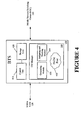
- Figure 4 depicts a block diagram of a base station that may be employed in the communications system of Figure 3, in accordance with one embodiment of the present invention;
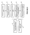
- Figure 5 depicts a flow diagram of a method for determining a PLCM for communications between a mobile unit and the base station of the communications system of Figure 3, in accordance with one embodiment of the present invention;
- Figure 6 depicts a graphical illustration for determining a longitudinal value based on a corresponding latitudinal value to determine the PLCM, in accordance with one embodiment of the present invention;
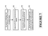
- Figure 7 illustrates a flow diagram of a method of assigning the determined PLCM value of Figure 5 for communications between the mobile unit and base station of the communications system of Figure 3; and
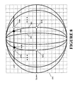
- Figure 8 is a stylized depiction of a portion of the Earth's surface illustrating a benefit gained by at least one embodiment of the present invention.
-
- While the invention is susceptible to various modifications and alternative forms, specific embodiments thereof have been shown by way of example in the drawings and are herein described in detail. It should be understood, however, that the description herein of specific embodiments is not intended to limit the invention to the particular forms disclosed, but on the contrary, the intention is to cover all modifications, equivalents, and alternatives falling within the spirit and scope of the invention as defined by the appended claims.
- Illustrative embodiments of the invention are described below. In the interest of clarity, not all features of an actual implementation are described in this specification. It will of course be appreciated that in the development of any such actual embodiment, numerous implementation-specific decisions must be made to achieve the developers' specific goals, such as compliance with system-related and business-related constraints, which will vary from one implementation to another. Moreover, it will be appreciated that such a development effort might be complex and time-consuming, but would nevertheless be a routine undertaking for those of ordinary skill in the art having the benefit of this disclosure.
- Turning now to the drawings, and specifically referring to Figure 3, a
communications system 100 is illustrated, in accordance with one embodiment of the present invention. For illustrative purposes, thecommunications system 100 of Figure 1 is a Code Division Multiple Access (CDMA) system, although it should be understood that the present invention may be applicable to other systems that support voice and/or data communication. A CDMA system is a "spread spectrum" technology, allowing many users to occupy the same time and frequency allocations in a given band/space. As its name implies, a CDMA system assigns unique codes to each communication to differentiate it from others in the same spectrum. A CDMA system includes second generation (2G) and third generation (3G) services. 2G CDMA standards are commonly known as CDMAONE and include the IS-95A and IS-95B standards. Two dominant standards for 3G services include CDMA2000 and wideband CDMA (CDMA2000 represents a family of technologies that includes CDMA2000-1X and CDMA2000-1xEV). - The
communications system 100 of Figure 1 includes a mobile services switching center (MSC) 110 that allows one or moremobile units 120 to communicate with a Public Switched Telephone Network (PSTN) 150 and/or adata network 155, such as the Internet, through one or more base stations (BTS) 130. The mobileservices switching center 110 of Figure 1 generally provides replication, communications, runtime, and system management services. The mobileservices switching center 110 may also handle call processing functions, such as setting and terminating a call path. Themobile unit 120 may include one of a variety of devices, including cellular phones, personal digital assistants (PDAs), laptops, digital pagers, wireless cards, and any other device capable of accessing thenetworks - In the
communications system 100 of Figure 1, the plurality ofbase stations 130 may be distributed within an area to be serviced by thesystem 100. Various users within the area, fixed or mobile, may then access thesystem 100 and, thus, other interconnected telecommunications systems, via one or more of thebase stations 130. Typically, a mobile user maintains communications with thesystem 100 as he/she passes through an area by communicating with one and then anotherbase station 130, as he/she moves. The user may communicate with theclosest base station 130, thebase station 130 with the strongest signal, thebase station 130 with a capacity sufficient to accept communications, etc. - The
base stations 130, in the illustrated embodiment, include a code mask (CM)manager 160 that, as described in greater detail below, manages (e.g., creates, assigns, tracks) code masks. In the illustrated embodiment, thecode mask manager 160 specifically manages public long code masks (PLCMs). Thecode mask manager 160 may be implemented in software, hardware, or a combination thereof. - In accordance with one or more embodiments of the present invention, an improved scheme is provided for determining and assigning PLCMs to facilitate communications with the
mobile units 120 in a manner that reduces the potential for collisions. Although not so limited, for the purposes of this discussion, the PLCMs are generated in accordance with the format shown in Figure 2. In one embodiment, theCM manager 160, in calculating a PLCM, takes into account the fact that the distance between the longitude lines decrease as one moves away from the equator. As described in greater detail below, in one embodiment, the PLCMs are generated by adjusting a value associated with the longitude of abase station 130 based on the latitude of thatbase station 130. In this manner, the potential for collisions is reduced. The latitudinal value and the longitudinal value associated with abase station 130 can be calculated in one of a variety of well-known techniques known in the art, and, as such, are not described in detail herein. - The
communications system 100 also allows for soft and hard handovers. In instances when users change between different service networks, a hard handoff is required. In accordance with one embodiment of the present invention, amobile unit 120 is assigned a new PLCM on a hard handoff, where the new PLCM will be based on the coordinates of thetarget base station 130. Assigning a new PLCM to themobile station 120 on a hard handoff reduces the potential for collisions. - It should be understood that the configuration of the
communications system 100 of Figure 1 is exemplary in nature, and that fewer, additional, or different components may be employed in other embodiments of thecommunications system 100 without deviating from the spirit and scope of the invention. For example, one or more routers (not shown) may be interspersed between theMSC 110 and thebases stations 130. As an additional example, thecommunications system 100 may include an Authentication, Authorization, and Accounting (AAA) server (not shown). Yet as another example, some or all portions of theCM manager 160 may be implemented in theMSC 110. Similarly, other modifications may be made to thecommunications system 100 consistent with the spirit and scope of the present invention. - Referring now to Figure 4, a block diagram of one embodiment of the
base station 130 is illustrated. Thebase station 130 includes acontrol unit 410 that is communicatively coupled to astorage unit 420 and is capable of executing one or more software instructions stored in the form of a program in thestorage unit 420. Thebase station 130 includes theCM manager 160, which in the illustrated embodiment is implemented in software and is storable in thestorage unit 420. TheCM manager 160 includes a generating module 140 and an assigning andtracking module 440. - The
generating module 430, described in greater detail in Figure 5, generally calculates the desired PLCMs for communications with themobile unit 120. In the illustrated embodiment, because thebase station 130 includes thegenerating module 430, thebase station 130 is capable of generating PLCMs on an as-needed basis. However, in an alternative embodiment, instead of creating PLCMs dynamically, apool 450 of PLCMs may be created in advance and pre-stored in thebase station 130 for subsequent use. The pre-stored PLCMs may be created using the same scheme (described below) that is employed by thegenerating module 430 to generate the PLCMs. In one embodiment, the PLCMs in thepool 450 can be reusable. That is, when a call is released, thebase station 130 that originally assigned the PLCM to themobile unit 120 can release that PLCM (into the pool 450) so that it is available for reuse. Thus, in instances where the PLCMs are pre-created and stored in thebase station 130, thegenerating module 430 may not be needed. The present invention contemplates the notion of dynamically creating PLCMs, creating and storing the PLCMs in advance of the use, or a combination of both where some portion of the PLCMs is pre-stored while the other portion is dynamically created. - The assigning and
tracking module 440 of thebase station 130 determines which PLCMs are available from thepool 450 and assigns one of the available PLCMs to amobile unit 120 desiring to establish a connection. The assigning andtracking module 440 thus tracks the PLCMs that are in use, and can determine which PLCMs are available for use. In the illustratedcommunications system 100 of Figure 1, when thebase station 130 that originally assigned the PLCM to amobile unit 120 is notified that the call has terminated, the module 140 of thatbase station 130 releases the assigned PLCM into thepool 450 for reuse. In one embodiment, thebase station 130 that originates the PLCM may be notified of the call termination even if thatbase station 130 is not the one handling the call at the time of termination (i.e., because there was a soft or a hard handover). In case of a soft or hard handover, thebase station 130 handling the call termination can notify the originatingbase station 130 that the call has terminated and that the assigned PLCM can be freed for future use. In one embodiment, the notification to the originatingbase station 130 may be transmitted through one or more interveningMSCs 110. - Referring now to Figure 5, a flow diagram of the
generating module 430 of thebase station 130 of Figure 4 is illustrated, in accordance with one embodiment of the present invention. For ease of illustration, the process of generating PLCMs is described in the context of asingle base station 130, although it should be appreciated that each generatingmodule 430 generates the PLCMs for itscorresponding base station 130 based on the geographical position or location of thatbase station 130. Alternatively, as discussed above, the PLCMs may be generated elsewhere and then stored in thecorresponding base stations 130. For the purposes of this discussion, it is assumed that eachbase station 130 has acorresponding generating module 430. - As shown in Figure 5, the
generating module 430 determines (at 505) the latitude associated with thebase station 130. This latitude may be represented using, for example, a 22-bit value, and may be expressed in "x" seconds. In one embodiment, the latitude may be pre-stored in thebase station 130, and, as such, the act of determining (at 505) the latitude may comprise retrieving the stored value. In the illustrated embodiment, it is assumed that the latitude is represented using a 22-bit value, although in other embodiments, a higher-bit or a lower-bit value may be used. Thegenerating module 430 modifies (at 510) the latitude of thebase station 130 to arrive at a different value (herein termed as a "modified latitude value). In one embodiment, this modified latitude value may be a lower-precision representation of the latitude that is determined atblock 505. For example, the modified latitude value may be determined by shifting the 22-bit value of the latitude of thebase station 130 by a preselected amount and then performing a MOD function. In one embodiment, the modified latitude value may be determined by shifting the 22-bit latitude value to the right by 5 bits to arrive at a 17-bit value. A MOD operation may then be performed on the 17-bit value to convert it to a lower-bit value, such as an 11-bit value, for example. As noted above, because generatingmodule 430 employs the PLCM format of Figure 2 for the purposes of this discussion, it is herein assumed that it is desirable to reduce the latitude of thebase station 130 to 11 bits, although it should be appreciated that in alternative embodiments other lengths may be utilized. - The
generating module 430 determines (at 520) the longitude of thebase station 130. This longitudinal value may be represented using, for example, a 23-bit value, and may be expressed in "y" seconds. In one embodiment, the longitude may be pre-stored in the base station, and, as such, the act of determining (at 505) the longitude may comprise retrieving the stored value. Thegenerating module 430 determines (at 530) a value associated with the determined longitude based on the latitude of thebase station 130. In one embodiment, the value associated with the longitude may be determined (at 530) by adjusting (at 532) the full 23-bit value of the longitude of thebase station 130 by a preselected amount, wherein the preselected amount is determined by the latitude of thebase station 130. The manner in which the longitudinal value of thebase station 130 may be adjusted (at 532) is better understood with reference to Figure 6. - As noted previously, because the distance between the longitude lines decrease as one moves away from the equator, the reusable distance similarly decreases. A reduced reusable distance, however, is undesirable because the potential for collisions is greater. Figure 6 illustrates a manner by which the reusable distance at a given latitude is maintained (i.e., ∼314 miles reusable distance and ∼0.15 miles of granularity), even as one moves away from the equator. This is accomplished, as shown in Figure 6, by adjusting the longitudinal value of the
base station 130 based on the latitude of thatbase station 130. - Figure 6, which is a stylistic representation of Earth's northern hemisphere, illustrates that the radius of a
circle 605 at a given latitude, "lat," can be expressed as "R x cos |lat|," where R is the radius of the circle at the equator. Thus, based on Figure 6, it can be seen that there is a shrinkage in the radius ofcircle 605 by a factor of about "cos |lat|" relative to that of the equator. To compensate for this shrinkage, in accordance with one embodiment of the present invention, and to maintain at least the same level of resolution as that present at the equator, the longitudinal value of thebase station 130 is adjusted by the "cos |lat| factor. Thus, instead of shifting the longitudinal value by five (5), as suggested by the proposal, in the illustrated embodiment, the longitudinal value is adjusted by a value based on the latitude of thebase station 130. For example, to achieve a resolution of 0.15 miles on thecircle 605, the longitudinal value may be calculated using the following expression Floor(longitude/(25/cos|lat|)), where the Floor function refers to rounding to the nearest, lower integer (or, put another way, using the quotient while discarding the remainder). - In the example shown in Figure 6, the
circle 605 is at 60 degrees latitude. Thus, at a latitude of 60 degrees, the expression "cos |60|" is 0.5, and the expression "25/cos|60|" is substantially equivalent to "26." Accordingly, at a latitude of 60 degrees, the longitudinal value is adjusted as follows: Floor(longitude/26) (i.e., the longitude value is divided 26, and the Floor function is applied thereafter to obtain the result). By dividing the longitudinal by 26 (at a latitude of 60 degrees), the resolution remains 0.15 miles even away from the equator, and that the reusable distance also remains the same as that at the equator. Similarly, the longitudinal values may be calculated for other latitudes using the expression: Floor(longitude/(25/cos|lat|)). Thus, by adjusting the longitude of thebase station 130 based on the latitude of thebase station 130, it is possible to achieve at least the same resolution as that available on the equator under the BSAPLCM proposal. For clarity and to avoid unnecessarily obscuring the invention, the conversions from degrees to minutes/seconds, and vice-versa, has been omitted, as one skilled in the art having the benefit of this disclosure can perform these desired conversions. - Referring again to Figure 5, the act of determining the value associated with the longitude of the base station 130 (at 530) may further include performing a MOD operation (at 534) on the adjusted (at 532) longitude value. In one embodiment, like the value associated with the latitude of the
base station 130, the value associated with the longitude of the base station is converted to an 11-bit value. - Based on at least the value associated with the longitude that is determined (at 530), the
generating module 430 generates (at 540) a PLCM in accordance with the format shown in Figure 2. In one embodiment, the determined longitudinal value (at 530) is concatenated with the determined latitude value (at 510). The concatenation of just these values means that the reusable distance will be at least ∼314 miles independent of the latitude. To complete the 42-bit PLCM, the MS ID, as well as the first three bits, is also concatenated in the manner shown in Figure 2. The leading 3 bits indicate that this is a BS assigned PLCM (e.g., as opposed to a MEID based PLCM). The MS_ID in the illustrated embodiment is a 17-bit value, although it can vary from one implementation to another. Thebase station 130 utilizes the MS_ID to uniquely identify themobile units 120 that it is servicing (that is, while eachmobile unit 120 communicating with acommon base station 130 will have the same latitude and longitude values as part of the PLCM that is assigned to thatmobile unit 120, the MS_ID portion of the PLCM will be different for each of thesemobile units 120. Thus, for at least a given cell, eachmobile unit 120 is assigned a unique identifier. In one embodiment, the MS_IDs may be uniquely partitioned among thebase stations 130 sharing the same 11-bit latitudinal and longitudinal value.
It should be appreciated that the format shown in Figure 2 is exemplary in nature and that any other manner of combining the longitudinal and the latitudinal values may also be utilized without deviating from the spirit and scope of the invention. The generated PLCM can thereafter be assigned to amobile unit 120 desiring to establish a connection with thebase station 130, as described below. Referring now to Figure 7, a flow diagram of the assigning andtracking module 440 of thebase station 130 of Figure 4 is illustrated, in accordance with one embodiment of the present invention. Once a call activation is detected by thebase station 130, the assigning andtracking module 440 determines (at 710) a PLCM to assign to amobile unit 120 desiring to communicate with thebase station 130. In one embodiment, the PLCM that is to be assigned to themobile unit 120 may be one that is generated (at 540 - see Figure 5) by thegenerating module 430. In an alternative embodiment, the assigning andtracking module 440 may determine (at 710) a PLCM to assign from the PLCM pool 450 (see Figure 4) of available PLCMs that are generated in accordance with the method described in Figure 5. In one embodiment, the assigning andtracking module 440 of thebase station 130 can use the MS_IDs to track which PLCMs are available and which are in use from the pool 450 (see Figure 3) of PLCMs. - At
block 720, thebase station 130 assigns the PLCM (determined at block 710) to themobile unit 120. Assigning the PLCM to themobile unit 120 may include informing themobile station 120 of that PLCM. This can be accomplished in one of several ways. In one embodiment, the PLCM may be transmitted over a suitable communications channel tomobile unit 120, which then codes the transmission using the PLCM, and thebase station 130 thereafter decodes the transmission using the PLCM. In an alternative embodiment, if the latitude and longitude of thebase station 130, along with the MS ID, are accessible to themobile unit 120, themobile unit 120 itself can, using the method described in Figure 5, calculate the PLCM. Thus, in this embodiment, thebase station 130 may not need to transmit the PLCM to themobile unit 120. - Upon assigning the PLCM (at 720), the
base station 130 may communicate with themobile unit 120. That is, thebase station 130 may decode (at 740) the information transmitted over a communications channel, such as a traffic channel, using the PLCM. And, once the call is terminated, the assigning andtracking module 440 releases (at 760) the PLCM assigned to themobile unit 120 so that it can be later reused for another call. - Figure 8 is a stylistic illustration of a portion of the Earth with one or more longitudinal lines 802superimposed therein. Figure 8 is provided to graphically depict the shortcoming of the BSAPLCM proposal, as well as to illustrate the improvement provided by one or more embodiments of the described invention. It should be understood that Figure 8 is not necessarily drawn to scale. A square grid 800has been superimposed on the Earth's surface in Figure 8 for the benefit of the reader. In Figure 8, a first
exemplary point 805a and a secondexemplary point 805b are utilized to represent the "reusable distance" (i.e., the distance after which the 11-bit longitudinal and latitudinal values may repeat). Under the BSAPLCM proposal, the "reusable distance" at latitude, LAT, decreases to a distance between the points 810a and 810b. With this reduced reusable distance, the potential for collisions is greater for reasons explained above. In contrast, with the advent of the claimed invention, the reusable distance at latitude, LAT, remains constant (as represented by the grid 800) relative to that provided by the BSAPLCM proposal with respect to the equator. By adjusting the longitude of thebase station 130 based on the latitude value of thebase station 130, the reusable distance is maintained, as shown bypoints 820a and 820b, thereby reducing the likelihood of collisions. - Unless specifically stated otherwise, or as is apparent from the discussion, terms such as "processing" or "computing" or "calculating" or "determining" or "displaying" or the like, refer to the action and processes of a computer system, or similar electronic computing device, that manipulates and transforms data represented as physical, electronic quantities within the computer system's registers and memories into other data similarly represented as physical quantities within the computer system's memories or registers or other such information storage, transmission or display devices.
- Those skilled in the art will appreciate that the various system layers, routines, or modules illustrated in the various embodiments herein may be executable control units (such as the control unit 410 (see Figure 4)). The
control unit 410 may include a microprocessor, a microcontroller, a digital signal processor, a processor card (including one or more microprocessors or controllers), or other control or computing devices. The storage devices referred to in this discussion may include one or more machine-readable storage media for storing data and instructions. The storage media may include different forms of memory including semiconductor memory devices such as dynamic or static random access memories (DRAMs or SRAMs), erasable and programmable read-only memories (EPROMs), electrically erasable and programmable read-only memories (EEPROMs) and flash memories; magnetic disks such as fixed, floppy, removable disks; other magnetic media including tape; and optical media such as compact disks (CDs) or digital video disks (DVDs). Instructions that make up the various software layers, routines, or modules in the various systems may be stored in respective storage devices. The instructions when executed by arespective control unit 410 causes the corresponding system to perform programmed acts. - The particular embodiments disclosed above are illustrative only, as the invention may be modified and practiced in different but equivalent manners apparent to those skilled in the art having the benefit of the teachings herein. Furthermore, no limitations are intended to the details of construction or design herein shown, other than as described in the claims below.
Claims (10)
- A method, the method comprising:defining a geographical position of a base station by a first coordinate value and a second coordinate value;modifying the first coordinate value based on the second coordinate value; andgenerating an identifier based on at least the modified first coordinate value.
- The method of claim 1, wherein the first coordinate value is a longitudinal value of the base station and the second coordinate value is a latitudinal value of the base station, and wherein modifying comprises modifying the longitudinal value based on the latitudinal value.
- The method of claim 2, wherein generating the identifier comprises generating a code mask and further comprising providing the code mask to a mobile unit in response to detecting a call activation.
- The method of claim 3, wherein generating the code mask comprises combining at least a portion of the latitudinal value, the modified longitudinal value, and an unique identification value.
- The method of claim 2, wherein the identification value is transmitted to a mobile unit and wherein the mobile unit calculates the code mask based on at least a portion of the latitudinal value, the modified longitudinal value, and the unique identification value.
- The method of claim 3, wherein modifying the longitudinal value comprises modifying the longitudinal value by a factor of "cosine |latitude|," where the "latitude" is the latitudinal value associated with the base station.
- The method of claim 6, wherein the longitudinal value is represented by a first preselected number of bits and wherein the modified longitudinal value is represented by a second preselected number of bits, and wherein modifying the longitudinal value comprises applying a Floor function on the modified longitudinal value and thereafter applying a MOD function.
- The method of claim 7, further comprising detecting a call termination and releasing the assigned code mask for subsequent reuse.
- The method of claim 7, further comprising receiving a call termination indication from a target base station and releasing the assigned code mask for subsequent reuse in response to receiving the call termination indication.
- The method of claim 7, further comprising:generating a plurality of code masks based on at least a portion of the latitudinal value, the modified longitudinal value, and an unique identification value;storing the plurality of code masks in a storage unit;identifying at least one unassigned plurality of the code masks; andproviding the identified code mask to the mobile unit.
Applications Claiming Priority (2)
| Application Number | Priority Date | Filing Date | Title |
|---|---|---|---|
| US641526 | 1984-08-16 | ||
| US10/641,526 US7596381B2 (en) | 2003-08-15 | 2003-08-15 | Generating a code mask based on geographical coordinate values |
Publications (1)
| Publication Number | Publication Date |
|---|---|
| EP1507428A1 true EP1507428A1 (en) | 2005-02-16 |
Family
ID=33565283
Family Applications (1)
| Application Number | Title | Priority Date | Filing Date |
|---|---|---|---|
| EP04254507A Withdrawn EP1507428A1 (en) | 2003-08-15 | 2004-07-28 | Generating a code mask based on geographical coordinate values |
Country Status (4)
| Country | Link |
|---|---|
| US (1) | US7596381B2 (en) |
| EP (1) | EP1507428A1 (en) |
| JP (1) | JP4542389B2 (en) |
| KR (1) | KR101118436B1 (en) |
Families Citing this family (11)
| Publication number | Priority date | Publication date | Assignee | Title |
|---|---|---|---|---|
| US7561556B2 (en) * | 2003-05-01 | 2009-07-14 | Lg Electronics Inc. | System and method for generating a public long code mask in a mobile communications system |
| US7813746B2 (en) * | 2003-10-24 | 2010-10-12 | Samsung Electronics Co., Ltd. | Wireless network using shared traffic channel mode of operation for broadcast services |
| KR100664110B1 (en) * | 2004-02-04 | 2007-01-04 | 엘지전자 주식회사 | How to Set Restrictions on Mobile Terminals |
| US7747275B2 (en) * | 2004-05-06 | 2010-06-29 | M-Stack Limited | Cell selection in mobile communications |
| US8260288B2 (en) * | 2005-01-13 | 2012-09-04 | Henti Tung | Method and apparatus for generating a unique identifier for a wireless device |
| US20070135147A1 (en) * | 2005-12-12 | 2007-06-14 | Declerck Daniel J | Long code mask collision mitigation on networks using pseudo ESNs |
| JP4641973B2 (en) * | 2006-05-10 | 2011-03-02 | 富士通株式会社 | One-way communication method, mobile station apparatus and radio base station apparatus |
| KR100926474B1 (en) | 2007-12-26 | 2009-11-13 | 경북대학교 산학협력단 | How to generate sensor node ID using position coordinate value |
| US9313720B2 (en) * | 2008-03-27 | 2016-04-12 | Qualcomm Incorporated | Power efficient small base station scanning and acquisition |
| US9386431B2 (en) * | 2008-08-05 | 2016-07-05 | Qualcomm Incorporated | Battery efficient method to search for preferred femtocell |
| WO2013165213A1 (en) * | 2012-05-04 | 2013-11-07 | Samsung Electronics Co., Ltd. | System and methods for addressing mobile station in wireless communication system |
Citations (2)
| Publication number | Priority date | Publication date | Assignee | Title |
|---|---|---|---|---|
| US6018667A (en) * | 1998-01-20 | 2000-01-25 | Motorola, Inc. | Method and apparatus for transmitting information regarding the synchronization status of a base station |
| US20020082017A1 (en) * | 2000-12-27 | 2002-06-27 | Kiyoshi Hattori | Mobile communication terminal unit, and handoff control method thereof |
Family Cites Families (6)
| Publication number | Priority date | Publication date | Assignee | Title |
|---|---|---|---|---|
| US6345233B1 (en) * | 1997-08-18 | 2002-02-05 | Dynamic Vehicle Safety Systems, Ltd. | Collision avoidance using GPS device and train proximity detector |
| KR100322001B1 (en) * | 1998-09-16 | 2002-06-22 | 윤종용 | Device and method for measuring position of mobile station in mobile communication system |
| JP3510204B2 (en) | 2000-12-11 | 2004-03-22 | アジア航測株式会社 | Transportation business management system using new geocode |
| US7103040B2 (en) * | 2001-11-19 | 2006-09-05 | Telefonaktieboaget Lm Ericsson (Publ) | Method and apparatus for identifying a node for data communications using its geographical location |
| US7113792B2 (en) * | 2002-10-01 | 2006-09-26 | Qualcomm Incorporated | Mobile station location |
| US7184744B1 (en) * | 2002-10-10 | 2007-02-27 | Itt Manufacturing Enterprises, Inc. | GPS enabled emergency messaging system |
-
2003
- 2003-08-15 US US10/641,526 patent/US7596381B2/en not_active Expired - Fee Related
-
2004
- 2004-07-28 EP EP04254507A patent/EP1507428A1/en not_active Withdrawn
- 2004-08-13 KR KR1020040063728A patent/KR101118436B1/en not_active Expired - Fee Related
- 2004-08-13 JP JP2004235692A patent/JP4542389B2/en not_active Expired - Fee Related
Patent Citations (2)
| Publication number | Priority date | Publication date | Assignee | Title |
|---|---|---|---|---|
| US6018667A (en) * | 1998-01-20 | 2000-01-25 | Motorola, Inc. | Method and apparatus for transmitting information regarding the synchronization status of a base station |
| US20020082017A1 (en) * | 2000-12-27 | 2002-06-27 | Kiyoshi Hattori | Mobile communication terminal unit, and handoff control method thereof |
Non-Patent Citations (2)
| Title |
|---|
| HIGUCHI K ET AL: "Fast cell search algorithm in DS-CDMA mobile radio using long spreading codes", VEHICULAR TECHNOLOGY CONFERENCE, 1997, IEEE 47TH PHOENIX, AZ, USA 4-7 MAY 1997, NEW YORK, NY, USA,IEEE, US, 4 May 1997 (1997-05-04), pages 1430 - 1434, XP010229096, ISBN: 0-7803-3659-3 * |
| PURVA R RAJKOTIA ET AL: "3GPP2 TSG-C SWG 2.3", 16 July 2003 (2003-07-16), XP055171073, Retrieved from the Internet <URL:ftp://ftp.3gpp2.org/TSGC/Working/2003/2003-08-Seoul/TSG-C-2003-08-Seoul/WG2/SWG2.3/C23-20030714-032R4_SAM_PLCM_text.doc> [retrieved on 20150220] * |
Also Published As
| Publication number | Publication date |
|---|---|
| JP4542389B2 (en) | 2010-09-15 |
| US7596381B2 (en) | 2009-09-29 |
| KR20050016240A (en) | 2005-02-21 |
| JP2005065292A (en) | 2005-03-10 |
| US20050037778A1 (en) | 2005-02-17 |
| KR101118436B1 (en) | 2012-03-09 |
Similar Documents
| Publication | Publication Date | Title |
|---|---|---|
| USRE49060E1 (en) | System and method for channel transport format allocation in a wireless communication system | |
| EP3456089B1 (en) | Validation of pal protection areas | |
| US6654609B2 (en) | Method for measuring location of mobile station and for performing handoff using the same in mobile communication system | |
| US8355364B1 (en) | Systems and methods for using topology to determine whether to grant an access request from an access terminal | |
| RU2376706C2 (en) | Method and device for increasing signal-to-noise ratio of location measurements | |
| US7738874B1 (en) | Method and system for frequency usage | |
| KR101066346B1 (en) | Broadcasting service apparatus and method using a shared channel in a wireless communication system | |
| US5887262A (en) | Smart antenna backwards compatibility in digital cellular systems | |
| CN103155667A (en) | Method and base station system for providing access to a mobile communication network | |
| US7596381B2 (en) | Generating a code mask based on geographical coordinate values | |
| US8958401B2 (en) | Method and apparatus for assisted network discovery | |
| JP2001516990A (en) | Method and apparatus for providing orthogonal spot beams, sectors and pico cells | |
| US6778833B1 (en) | Method for allocating identifiers in a cellular wireless network | |
| WO2021028255A1 (en) | Ntn country area specific low delay access | |
| KR20060105800A (en) | Code Channel Management in Wireless Communication Systems | |
| US8818403B1 (en) | Adjusting wireless coverage area resource assignment based on device altitude | |
| JP5601967B2 (en) | Support for multiple chip rates in CDMA systems | |
| US7702285B2 (en) | System and method for determining mobile communication system carrier frequency propagation characteristics | |
| US9775118B2 (en) | Offset to data rate control based on transmission power in neighbor sector | |
| US9008032B2 (en) | Frequency band setting apparatus and method, access point, and frequency band using method of access point | |
| US20240373412A1 (en) | Spectrum management of overlapping bandwidth | |
| KR20010072744A (en) | Layered wireless communication system and method | |
| US20050221835A1 (en) | Method and apparatus for call setup | |
| US8391412B1 (en) | PN long code shift for access attempt | |
| US8818402B1 (en) | Adjusting initial wireless coverage area transmit power based on device altitude |
Legal Events
| Date | Code | Title | Description |
|---|---|---|---|
| PUAI | Public reference made under article 153(3) epc to a published international application that has entered the european phase |
Free format text: ORIGINAL CODE: 0009012 |
|
| 17P | Request for examination filed |
Effective date: 20040813 |
|
| AK | Designated contracting states |
Kind code of ref document: A1 Designated state(s): AT BE BG CH CY CZ DE DK EE ES FI FR GB GR HU IE IT LI LU MC NL PL PT RO SE SI SK TR |
|
| AX | Request for extension of the european patent |
Extension state: AL HR LT LV MK |
|
| 17Q | First examination report despatched |
Effective date: 20050406 |
|
| AKX | Designation fees paid |
Designated state(s): DE FR GB |
|
| 17Q | First examination report despatched |
Effective date: 20050406 |
|
| RAP3 | Party data changed (applicant data changed or rights of an application transferred) |
Owner name: LUCENT TECHNOLOGIES INC. |
|
| RAP1 | Party data changed (applicant data changed or rights of an application transferred) |
Owner name: ALCATEL-LUCENT USA INC. |
|
| 111Z | Information provided on other rights and legal means of execution |
Free format text: DE FR GB Effective date: 20130410 |
|
| D11X | Information provided on other rights and legal means of execution (deleted) | ||
| GRAP | Despatch of communication of intention to grant a patent |
Free format text: ORIGINAL CODE: EPIDOSNIGR1 |
|
| RIC1 | Information provided on ipc code assigned before grant |
Ipc: H04W 88/08 20090101AFI20151005BHEP |
|
| INTG | Intention to grant announced |
Effective date: 20151023 |
|
| STAA | Information on the status of an ep patent application or granted ep patent |
Free format text: STATUS: THE APPLICATION IS DEEMED TO BE WITHDRAWN |
|
| 18D | Application deemed to be withdrawn |
Effective date: 20160303 |