Background of the Invention:
Field of the Invention:
The present invention relates to a projection display device that is provided
with a reflective image display element, and more particularly, to prism optics
for both guiding illuminating light to an image display element and guiding the
light that is reflected from the image display element to projection optics.
Description of the Related Art:
The development of projection display devices has made rapid strides in recent
years, and demand is growing for more compact and lower-cost projectors.
This demand is accompanied by a growing need for more compact devices
that for use in projection display devices. Meeting this demand calls for the
development of more compact peripheral parts, and in particular, for more
compact optics that accompany the reduction of the size of these devices, so
that the overall size of a projection display device can be decreased. Recent
years have seen the development of the time-division image projection device
having a basic structure that extracts and projects the colors red, green, and
blue in time divisions. For example, as disclosed in Japanese Patent Laid-Open
Publication No. 78550/98, a DMD projector is known that uses a digital
mirror device (hereinbelow abbreviated "DMD"), in which several hundred
thousand individual mirror elements having various controllable inclinations are
attached over semiconductor memory cells, whereby the inclination of each
mirror element is manipulated to control the reflection state and thus form an
image.
As shown in FIG. 1, this DMD projector is configured such that light that is
emitted from light source 101 is reflected by reflecting mirror 102 and then
condensed by condensing lens 103 to one point of color wheel 104 in which
color filters that selectively pass red, green and blue light are combined. The
light that is thus passed is made uniform by integrator rod 105, irradiated as a
parallel flux by optics 109 such as a relay lens onto DMD 107 by way of TIR
prism (total internal reflection prism) 106, and the image light, which is the light
reflected by DMD 107, is projected by way of zoom projection lens 108 onto a
screen. In this case, TIR prism 106 is configured such that two prisms having
different indices of refraction are bonded together, whereby the illumination
light that is irradiated onto the bonded surface is reflected and irradiated upon
DMD 107, and light that is reflected from DMD 107 is transmitted through the
bonded surface and emitted from prism 106 to projection lens 108. Regarding
the structure of this TIR prism, the configuration disclosed in Japanese Patent
No. 3060049 or Japanese Patent No. 3065058 may be adopted.
The TIR prism in this DMD projector of the prior art has a configuration in which
two prisms are bonded for total reflection as well as transmission of illumination
light. In addition, this TIR prism requires the previously described light-condensing
relay lens in the stage preceding the TIR prism. This arrangement
results in an increase in space for mounting the optical element portion that is
disposed in the space between the integrator rod and the projection lens and
therefore poses a serious obstacle to creating a compact projection display
device. The same problem exists in a projection display device that employs a
reflective liquid crystal panel as the image display element.
Summary of the Invention:
It is an object of the present invention to provide a compact projection display
device in which a single prism and a single relay lens make up the optics for
illuminating the image display element.
In a projection display device that is provided with: a relay lens for making flux
that is emitted from a light source, a parallel flux for illuminating an image
display element, and a total internal reflection prism that both guides the flux
that is emitted from the relay lens to the image display element and directs the
flux that is reflected by the image display element toward a projection lens; the
feature of the present invention is the unification of the relay lens with the prism
by bonding the relay lens to the total internal reflection surface of the prism.
The present invention, by bonding a single lens to a single prism, not only
allows flux that is emitted from a light source to be irradiated upon an image
display element, but also allows the light that is reflected from the image
display element to be directed toward the projection lens, whereby, in
comparison with a device that is configured with separate relay lens and TIR
prism as in the prior art, the present invention enables a reduction of the cubic
volume and space of the optics, allows the realization of a more compact
projection display device, and further, achieves a lower cost. In addition,
despite this configuration, the flux that is incident to the prism and the flux that
is emitted from the prism are directed in different directions, and as a result, no
interference occurs between the incident flux and the emitted flux.
The above and other objects, features, and advantages of the present
invention will become apparent from the following description with reference to
the accompanying drawings, which illustrate examples of the present invention.
Brief Description of the Drawings:
FIG. 1 shows the configuration of an example of a projection display device of
the prior art.
FIG. 2 is a perspective view showing the general configuration of a projection
display device of the present invention.
FIG. 3 is an exploded perspective view of a lens-integral prism.
FIG. 4 is a side view of the lens-integral prism in an assembled state.
FIG. 5 is a schematic side view showing the light path in the lens-integral prism.
FIG. 6 is a schematic side view for explaining the method of finding the
minimum dimensions of the lens-integral prism.
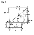
FIG. 7 is a schematic side view for explaining the method of finding the
minimum thickness dimension of a lens-integral prism.
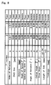
FIG. 8 is a table showing examples of the minimum dimensions of a lens-integral
prism.
Detailed Description of the Preferred Embodiments:
In the present invention, a prism is configured such that the sectional profile in
the direction along the optical axis is an isosceles triangle, the surface of the
base of this triangle is the total internal reflection surface, one of the inclined
surfaces is arranged to confront the image display elements, and the other
inclined surface is arranged to confront the projection lens. In this case, a
micro-spaced air gap is preferably interposed at the bonded surface between
the relay lens and prism. In this case, the relay lens is bonded to the prism
using an adhesive with added glass beads to realize bonding in a state that
maintains a micro-spacing between the relay lens and prism. In addition, the
relay lens is constituted by a piano-convex lens, and is configured with its flat
surface bonded to the total internal reflection surface of the prism. The lens
edge and sand-floated surface of the relay lens are preferably subjected to a
black-coating process. Still further, reinforcing plates are preferably arranged
for joining the relay lens and prism.
A working example of the present invention is next explained with reference to
the figures. FIG. 2 is an overall view of a DMD projector that employs a DMD
as a reflective image display element. Parts that are the same as in the prior
art are given the same reference numerals. Light that is emitted from light
source 1 is reflected by reflecting mirror 2, condensed by condensing lens 3 to
one point of color wheel 4 in which color filters that selectively pass red, green,
and blue light are combined, and this passed light is then made uniform by
integrator rod 5. The light that is emitted from integrator rod 5 is incident to one
surface of lens-integral prism 6 according to the present invention, emitted from
the other surface as a parallel flux, and illuminates DMD 7, which is the image
display element. The image light, which is the reflected light of DMD 7, is
irradiated into lens-integral prism 6, again emitted from the other surface, and
projected onto a screen (not shown) by way of projection lens 8 having a zoom
configuration.
Lens-integral prism 6 is composed of prism 61 in which the sectional profile is
an isosceles triangle and relay lens 62 that is bonded to base surface 61a of
this prism 61. The two inclined surfaces 61b and 61c that are on either side of
base surface 61a of prism 61 are each formed as a square or rectangle, one
inclined surface 61b being arranged so as to confront DMD 7, and the other
inclined surface 61c being arranged to confront projection lens 8. Relay lens 62
is configured with portions cut from the circumference of a plano-convex lens,
flat surface 62a being bonded to base surface 61a of prism 61. Relay lens 62 is
a construction that is subjected to a blackening process to suppress stray light
that is diffusely reflected by surfaces having a curved portion, i.e., (lens edge)
62b and the cut surfaces of the lens (sand-floated surface) 62c.
In addition, the bonding surface of relay lens 62 and prism 61 is configured so
as to have air gap 63 of micro dimensions between the confronting surfaces as
shown in FIG. 4, and the difference between the index of refraction of prism 61
and the index of refraction of air causes total internal reflection at the inner
surface of base surface 61a of prism 61. A UV-hardening adhesive with a glass
bead additive is used to produce this air gap 63, the adhesive being applied
over the entire surface or edges of the bonding surfaces and the two surfaces
then bonded together to ensure a gap that corresponds to the diameter
dimension of the glass beads. Further, in this case, a configuration is adopted
for preventing a split between relay lens 62 and prism 61 caused from
degrading the bonding strength between the two components by the heat of
the light source, which is produced when driving the projector. According to this
configuration, reinforcing plates 64 composed of glass plates are adhered by
adhesive 64a to surfaces that have no relation to the transmission and
reflection of light, for example, to at least one surface that is parallel to the
plane of FIG. 4. The area of adhesion of adhesive 64a that is used at this time
is greater than the area of adhesion between relay lens 62 and prism 61 and
the adhesive strength is therefore stronger than the adhesion between relay
lens 62 and prism 61. In other words, reinforcing plates 64 have greater
resistance to the failure of adhesion resulting from heat.
By means of lens-integral prism 6 that is thus constituted, flux from light source
1 is emitted from integrator rod 5 in a diffuse state, directed to the convex
surface of relay lens 62, emitted from the planar surface of relay lens 62 as a
parallel beam, and then directed into base surface 61a of prism 61, as shown
by the light path in FIG. 5. The flux that is incident to prism 61 is transmitted in
the interior of prism 61 and emitted from one inclined surface 61b to irradiate
DMD 7. The flux that has been optically modulated by reflection at DMD 7 is
again directed into prism 61 from one inclined surface 61b, projected on the
inner surface of base surface 61a at an angle with respect to base surface 61a
that is greater than the critical angle, and is here subjected to total internal
reflection. The critical angle is the angle of incidence at which total internal
reflection occurs at the interface where light is irradiated at a particular angle
from a medium having a high index of refraction (index of refraction n1) to a
medium having a low index of refraction (index of refraction n0), critical angle
c being represented by sin c = n0 / n1. Light that undergoes total internal
reflection at base surface 61a is emitted from the other inclined surface 61c of
prism 61 and directed to projection lens 8, whereby the image that is displayed
by DMD 7 is projected onto a screen (not shown) by projection lens 8.
As described in the foregoing explanation, by adhering a single relay lens 62 to
a single prism 61 in lens-integral prism 6 of the present working example, flux
that is emitted from integrator rod 5 can be irradiated into DMD 7, and the
reflected light from DMD 7 can be guided to projection lens 8. Thus, compared
to a case in which a condensing lens and TIR prism are realized as separate
components as in the prior art, the space and volume of the optics can be
reduced and a more compact projection display device can be realized. Further
this configuration, compared to a configuration that requires one lens and two
prisms as in the prior art, enables the elimination of one prism and therefore
can realize a reduction in cost. Still further, the flux that is incident to prism 61
has a different direction than the flux that is emitted from the same prism 61,
and interference is therefore not produced between the incident flux and the
emitted flux.
In the present working example, air gap 63 is provided at the bonding surface
between relay lens 62 and prism 61 to secure the critical angle for producing
total internal reflection of the light that is reflected from DMD 7, but relay lens
62 and prism 61 may also be bonded by using an adhesive sheet or
transparent adhesive having a low index of refraction and having superior light
permeability. Alternatively, relay lens 62 and prism 61 can also be bonded in a
directly contacting state when the index of refraction of relay lens 62 is lower
than the index of refraction of prism 61.
The nest explanation is regard to an example of forming lens-integral prism 6
of the present invention in the minimum compact size. First, in prism 61 in FIG.
5, DMD 7 and one inclined surface 61b (surface AC in FIG. 5) must be parallel,
and projection lens 8 and the other inclined surface 61c (surface BC in FIG. 5)
must be parallel, whereby the optical axis of inclined surface 61b is always
perpendicular to the optical axis of inclined surface 61c. Accordingly, angle
ATU and angle BVU are each 90°. In addition, the angle of incidence and the
angle of reflection of a light ray are equal, and angle AUT is equal to angle
BUV, and triangle ATU is similar to triangle BVU. The two side angles 1 and
2 of prism 61 are therefore equal and prism 61 can be recognized as an
isosceles triangle.
The nest explanation is regard to the size of prism 61. Prism 61 must be large
enough to receive and emit all flux that are reflected by the effective area of
DMD 7. For this purpose, the conditions that are necessary for finding the size
and shape of a prism that can subject all flux to total internal reflection, and
moreover, that can contain all flux that are reflected by the effective area of
DMD 7 are shown; and the minimum size of a prism that satisfies the
conditions is found by substituting the fixed values (the F-number of projection
lens 8 and the size of the effective area of DMD 7) in the conditional
expression that has been found.
The schematic figure of FIG. 6 is used to explain the calculation of the
minimum size of prism 61 based on the size of the effective area of DMD 7 and
the F-number of projection lens 8. The drawing on the left side of the figure is
an enlarged detail of the portion that is enclosed within circle S on the right side
of the figure. Flux that are reflected by the two ends of effective area surface
EF of DMD 7 have a spread of angle , and are incident to one inclined surface
61 b (hereinbelow referred to as the "incident surface") AC of the prism. One of
the conditions for the smallest size of prism 61 is that light ray AE, that is on
the extreme left, be incident to apex A of the prism (that AA' be equal to 0).
One of the conditions for the smallest size of the prism is that light ray DF on
the extreme right enter incident surface AC of prism 61 and be incident to the
extreme end (apex B) of inclined surface 61a of prism 61 (surface AB in FIG. 6
and referred to as the "total internal reflection surface"). The minimum size of
prism 61 is determined by satisfying these two conditions, and moreover, by
satisfying the condition that light ray AE enter incident surface AC and that the
angle of incidence of this ray to the total internal reflection surface AB of the
prism be the critical angle.
Light rays that are reflected by the two ends of the effective area of DMD 7
have a fixed spread, and the angle of this spread is determined by the F-number
of projection lens 8. The relation between the F-number and spread is
represented by:
F = 1/ (2 sin )
where F is the F-number and is the angle of spread.
If α is the angle between the optical axis of flux that is reflected by DMD 7 and
a line that is perpendicular to the incident surface AC of prism 61, n is the index
of refraction of prism 61, ω is the angle of emission of a light ray on the
extreme left that is incident to incident surface AC, β is the angle of refraction
of the optical axis when incident to incident surface AC, and ψ is the angle of
emission of a light ray on the extreme right end, Snell's Law gives:
n • sin β = sin α
n • sin ω = sin |α - /2|
n • sin ψ = sin (α + /2)
If γ is the angle of apex A of prism 61, and c is the critical angle, then a
condition is held that is satisfied by:
c ≥ γ - ω
when α ≤ /2, and:
c ≥ γ + ω
when α ≥ /2. Here, if the index of refraction of air is 1, then
sin c = 1/n
As a result, when the angle of incidence of the end flux is the critical angle,
then γ is found from:
γ = c ± ω = sin-1 (1/n) ± ω
For prism 61 to subject all flux to total internal reflection, all flux must first be
incident to incident surface AC. The ability of light ray FD on the extreme right
to enter incident surface AC and be incident to total internal reflection surface
AB is also a condition for determining the size of prism 61. Considering
isosceles triangle ABC (AC = BC), the length of AD is:
AD = x + z [tan (α + /2) - tan |α - /2|]
where x is the length of the sides of DMD 7 that are parallel to the plane of the
figure, y is the length of the sides that are perpendicular to the plane of the
figure (in the direction of depth of the figure), z is the distance between prism
61 and DMD 7, and D is the point of incidence of the flux on the extreme right
that is incident to incident surface AC from DMD 7.
If G is the point of intersection between the line that is perpendicular to incident
surface AC at point of incidence D and total internal reflection surface AB, H is
the point of intersection between the perpendicular line that descends from
apex B and incident surface AC, I is the point of intersection of perpendicular
BH and the line that is perpendicular to BH that passes through point G, and J
is the point of intersection between BD and GI, then:
AG = AD / cos γ
HI = DG = AD • tan γ
Further, based on the triangle GDJ:
GJ = DG • tan ψ
Still further, based on triangles ABD and GBJ:
AG : AD = GB : GJ
From this relation is obtained:
GB = AG • GJ / AD
Substituting Equation 10 and Equation 11 for AG and GJ of Equation 14 yields:
GB = [(AD / cos γ) × (DG • tan ψ)] / AD
Further, substituting Equation 11 for DG of Equation 15 yields:
GB = [(AD / cos γ) × (AD • tan γ • tan ψ)] / AD
= AD • tan γ • tan ψ / cos γ
Based on triangle BGI:
BI = GB • sin γ
Substituting Equation 16 for GB of Equation 17 yields:
Bl= AD • tan γ • tan ψ • sin γ / cos γ
= AD • tan2γ • tan ψ
Based on the relation angle ABC = angle BAC = γ:
Angle BCH = π - 2γ
Based on triangle BCH:
BC = BH / sin (π - 2γ) = [BI + HI] / sin 2γ
Substituting Equation 18 and Equation 11 for BI and HI of Equation 20 yields:
AC = BC = (AD • tan2γ • tan ψ + AD • tan γ) / sin 2γ
= AD • tan γ (tan γ • tan ψ + 1) / sin 2γ
= AD • (tan γ • tan ψ + 1) / 2 cos2γ
Still further:
BH = AD • tan γ • (tan γ • tan ψ + 1)
Accordingly, substituting Equation 9 for AD of Equation 21 yields:
AC = BC = {x + z [tan (α + /2) - tan |α - /2|]} •
(tan γ • tan ψ + 1) / 2 cos2 γ
Further, since:
AB = BH / sin γ = [BI + HI] / sin γ
then, substituting Equation 18 and Equation 11 for BI and HI of Equation 24
yields:
AB = AD • tan γ (tan γ • tan ψ + 1) / sin γ
Accordingly, substituting Equation 9 for AD of Equation 25 yields:
AB = {x + z [tan (α + /2) - tan |α - /2|]} • (tan γ • tan ψ + 1) / cos γ
The length of each side of the apices ABC of prism 61 that takes the form of an
isosceles triangle can be determined based on the foregoing explanation, and
these are the minimum lengths of each side of prism 61.
The minimum size of prism 61 in the direction of thickness (the direction
perpendicular to the plane of the figure) is next determined. The length of the
optical axis of flux that is reflected at the center of DMD 7 to reach surface BC,
i.e., emission surface BC, is first found. FIG. 7 schematically shows the state in
which prism 61 and a similar prism 61' are joined together at the base surfaces
and flux from DMD 7 is transmitted as far as prism 61' without being reflected
at total internal reflection surface AB. KLN shows the flux at this time.
In this case, prisms 61 and 61' have the same isosceles triangular shape, and
as a result:
KL + LM = KN
Here:
KN = OK/ cos β = BH / cos β
The length PK of the optical axis from DMD to the prism is:
PK = z / cos α
Distance I for the optical axis of flux that is reflected at the center of DMD 7 to
reach emission surface BC, based on Equation 28, Equation 29, and BH of
Equation 22 is:
I = PK + KN = [z / cos α]
+ [AD • tan γ (tan y • tan ψ + 1)/ cos β]
Since flux has a cone-shaped spread, the diameter R of the circle of flux that is
reflected at the center of DMD 7, that spreads at an angle , and that has
traveled a distance I can be found by using Equation 30:
R = 2 • | • tan (/2) = 2 tan (/2) • {[z / cos α]
+ [AD • tan γ (tan γ • tan ψ + 1) / cos β]}
Accordingly, the minimum thickness Y of prism 61 can be found by adding
length y of the thickness of the DMD to the diameter R of the circle that has
been found, and based on Equation 30, this is:
Y = 2 tan (/2) • {[z / cos α]
+ [AD • tan γ (tan γ • tan ψ + 1) / cos β]} + y
The above-described Equation 23, Equation 26, and Equation 32 are
the minimum dimensions for sides AC, BC, AB and thickness Y of a suitable
prism that is used in the projection display device of the present invention.
In this case, the size and thickness of prism 61 is determined by the F-number
of projection lens 8 and the size of the effective area of DMD 7, but finding the
accurate prism size obviously requires finding the angle of incidence of the
optical axis to prism 61 of flux that is reflected by DMD 7 and the distance
between DMD 7 and prism 61. FIG. 8 shows two examples for finding the
thickness Y and the length of each side AB, AC, and BC of prism 61 when the
angle of incidence α of flux to prism 61 is 5° and the distance z between DMD
7 and prism 61 is 10 mm.
The image display element in the present invention is not limited to the above-described
DMD, and the present invention can also be applied to a projection
display device that uses a reflecting liquid crystal panel.
It is to be understood, however, that although the characteristics and
advantages of the present invention have been set forth in the foregoing
description, the disclosure is illustrative only, and changes may be made in the
arrangement of the parts within the scope of the appended claims.