EP1507167A1 - Self-contained manual lifting screen - Google Patents
Self-contained manual lifting screen Download PDFInfo
- Publication number
- EP1507167A1 EP1507167A1 EP03728042A EP03728042A EP1507167A1 EP 1507167 A1 EP1507167 A1 EP 1507167A1 EP 03728042 A EP03728042 A EP 03728042A EP 03728042 A EP03728042 A EP 03728042A EP 1507167 A1 EP1507167 A1 EP 1507167A1
- Authority
- EP
- European Patent Office
- Prior art keywords
- screen
- arms
- lower side
- members
- slide members
- Prior art date
- Legal status (The legal status is an assumption and is not a legal conclusion. Google has not performed a legal analysis and makes no representation as to the accuracy of the status listed.)
- Withdrawn
Links
Images





Classifications
-
- F—MECHANICAL ENGINEERING; LIGHTING; HEATING; WEAPONS; BLASTING
- F16—ENGINEERING ELEMENTS AND UNITS; GENERAL MEASURES FOR PRODUCING AND MAINTAINING EFFECTIVE FUNCTIONING OF MACHINES OR INSTALLATIONS; THERMAL INSULATION IN GENERAL
- F16M—FRAMES, CASINGS OR BEDS OF ENGINES, MACHINES OR APPARATUS, NOT SPECIFIC TO ENGINES, MACHINES OR APPARATUS PROVIDED FOR ELSEWHERE; STANDS; SUPPORTS
- F16M11/00—Stands or trestles as supports for apparatus or articles placed thereon ; Stands for scientific apparatus such as gravitational force meters
- F16M11/20—Undercarriages with or without wheels
- F16M11/24—Undercarriages with or without wheels changeable in height or length of legs, also for transport only, e.g. by means of tubes screwed into each other
- F16M11/38—Undercarriages with or without wheels changeable in height or length of legs, also for transport only, e.g. by means of tubes screwed into each other by folding, e.g. pivoting or scissors tong mechanisms
-
- G—PHYSICS
- G03—PHOTOGRAPHY; CINEMATOGRAPHY; ANALOGOUS TECHNIQUES USING WAVES OTHER THAN OPTICAL WAVES; ELECTROGRAPHY; HOLOGRAPHY
- G03B—APPARATUS OR ARRANGEMENTS FOR TAKING PHOTOGRAPHS OR FOR PROJECTING OR VIEWING THEM; APPARATUS OR ARRANGEMENTS EMPLOYING ANALOGOUS TECHNIQUES USING WAVES OTHER THAN OPTICAL WAVES; ACCESSORIES THEREFOR
- G03B21/00—Projectors or projection-type viewers; Accessories therefor
- G03B21/54—Accessories
- G03B21/56—Projection screens
- G03B21/58—Projection screens collapsible, e.g. foldable; of variable area
-
- F—MECHANICAL ENGINEERING; LIGHTING; HEATING; WEAPONS; BLASTING
- F16—ENGINEERING ELEMENTS AND UNITS; GENERAL MEASURES FOR PRODUCING AND MAINTAINING EFFECTIVE FUNCTIONING OF MACHINES OR INSTALLATIONS; THERMAL INSULATION IN GENERAL
- F16M—FRAMES, CASINGS OR BEDS OF ENGINES, MACHINES OR APPARATUS, NOT SPECIFIC TO ENGINES, MACHINES OR APPARATUS PROVIDED FOR ELSEWHERE; STANDS; SUPPORTS
- F16M11/00—Stands or trestles as supports for apparatus or articles placed thereon ; Stands for scientific apparatus such as gravitational force meters
- F16M11/20—Undercarriages with or without wheels
- F16M11/24—Undercarriages with or without wheels changeable in height or length of legs, also for transport only, e.g. by means of tubes screwed into each other
- F16M11/26—Undercarriages with or without wheels changeable in height or length of legs, also for transport only, e.g. by means of tubes screwed into each other by telescoping, with or without folding
-
- G—PHYSICS
- G03—PHOTOGRAPHY; CINEMATOGRAPHY; ANALOGOUS TECHNIQUES USING WAVES OTHER THAN OPTICAL WAVES; ELECTROGRAPHY; HOLOGRAPHY
- G03B—APPARATUS OR ARRANGEMENTS FOR TAKING PHOTOGRAPHS OR FOR PROJECTING OR VIEWING THEM; APPARATUS OR ARRANGEMENTS EMPLOYING ANALOGOUS TECHNIQUES USING WAVES OTHER THAN OPTICAL WAVES; ACCESSORIES THEREFOR
- G03B21/00—Projectors or projection-type viewers; Accessories therefor
- G03B21/54—Accessories
- G03B21/56—Projection screens
- G03B21/60—Projection screens characterised by the nature of the surface
-
- F—MECHANICAL ENGINEERING; LIGHTING; HEATING; WEAPONS; BLASTING
- F16—ENGINEERING ELEMENTS AND UNITS; GENERAL MEASURES FOR PRODUCING AND MAINTAINING EFFECTIVE FUNCTIONING OF MACHINES OR INSTALLATIONS; THERMAL INSULATION IN GENERAL
- F16M—FRAMES, CASINGS OR BEDS OF ENGINES, MACHINES OR APPARATUS, NOT SPECIFIC TO ENGINES, MACHINES OR APPARATUS PROVIDED FOR ELSEWHERE; STANDS; SUPPORTS
- F16M2200/00—Details of stands or supports
- F16M2200/04—Balancing means
- F16M2200/044—Balancing means for balancing rotational movement of the undercarriage
-
- F—MECHANICAL ENGINEERING; LIGHTING; HEATING; WEAPONS; BLASTING
- F16—ENGINEERING ELEMENTS AND UNITS; GENERAL MEASURES FOR PRODUCING AND MAINTAINING EFFECTIVE FUNCTIONING OF MACHINES OR INSTALLATIONS; THERMAL INSULATION IN GENERAL
- F16M—FRAMES, CASINGS OR BEDS OF ENGINES, MACHINES OR APPARATUS, NOT SPECIFIC TO ENGINES, MACHINES OR APPARATUS PROVIDED FOR ELSEWHERE; STANDS; SUPPORTS
- F16M2200/00—Details of stands or supports
- F16M2200/06—Arms
- F16M2200/061—Scissors arms
-
- F—MECHANICAL ENGINEERING; LIGHTING; HEATING; WEAPONS; BLASTING
- F16—ENGINEERING ELEMENTS AND UNITS; GENERAL MEASURES FOR PRODUCING AND MAINTAINING EFFECTIVE FUNCTIONING OF MACHINES OR INSTALLATIONS; THERMAL INSULATION IN GENERAL
- F16M—FRAMES, CASINGS OR BEDS OF ENGINES, MACHINES OR APPARATUS, NOT SPECIFIC TO ENGINES, MACHINES OR APPARATUS PROVIDED FOR ELSEWHERE; STANDS; SUPPORTS
- F16M2200/00—Details of stands or supports
- F16M2200/06—Arms
- F16M2200/063—Parallelogram arms
Definitions
- the present invention relates to a self-standing manually operated elevating screen which is constructed so that the screen can be deployed upward by lifting an upper-end supporting member by hand, and so that the deployed screen can be taken up and accommodated inside a casing by pushing the upper-end supporting member downward, thus allowing the screen to be carried.
- a screen which is constructed so that the left and right ends of an upper-end supporting member and the left and right ends of a supporting frame are connected and supported by means of left and right linking mechanisms consisting of upper-end side arms and supporting-frame side arms, thus making it possible to accomplish the smooth extension and retraction of the linking mechanisms with good stability, and to cause the screen to stand by itself with good stability, has already been proposed as a screen which solves the abovementioned problems (for example, see Japanese Patent No. 3243037 (Fig. 1)).
- the abovementioned screen disclosed in Japanese Patent No. 3243037 has a construction in which the left and right linking mechanisms can be freely extended and retracted independently of each other, and has a construction in which the left and right linking mechanisms are caused to move in linkage with one end [of each linking mechanism] connected to the upper-end supporting member. Accordingly, if the screen is pushed downward by way of the left or right end portion of the upper-end supporting member of the screen in a deployed state, the upper-end supporting member will first drop considerably on the side that is pushed, thus causing this member to assume an inclined attitude, so that the linking mechanism on the side that has dropped is greatly shortened. As a result, a large load is applied only to the linking mechanism on the shortened side, and this may lead to deformation or damage of the linking mechanism.
- the self-standing manually operated elevating screen of the present invention is characterized in that: a take-up member to which one end of the screen is connected in order to take up the screen is attached to a base member in a state in which this take-up member is urged in the take-up direction; the base member and an upper-end supporting member to which the other end of the screen is connected are pivot-connected by linking mechanism formed by the pivot connection of upper side arms and lower side arms, with the linking mechanisms being separated into the left and right sides of the approximate center of the screen with respect to the transverse direction thereof; the pivot connection part of the upper side arm disposed on the left side in the transverse direction of the screen and the lower side arm disposed on the same side is disposed on the right side with respect to the transverse center portion of the upper-end supporting member, and the pivot connection part of the upper side arm disposed on the right side in the transverse direction of the screen and the lower side part disposed on the same side is disposed on the left side with respect to the transverse
- the screen can be smoothly and stably supported by the extension and retraction of the linking mechanisms disposed on the left and right sides when the screen is pulled upward (raised) and placed in the attitude of use, or when the screen is pushed downward and placed in an accommodated attitude. Furthermore, for example, if the right end or left end (with respect to the transverse direction of the screen) of the upper-end supporting member of the screen in the deployed state (use state) is pushed downward, or if the right end or left end (with respect to the transverse direction of the screen) of the upper-end supporting member of the screen in the accommodated state is pulled upward, the amounts of extension or retraction of the left and right linking mechanisms, i. e., the swinging angles of the left and right arms, will differ.
- the connected slide members cannot slide (move).
- the extension and retraction actions of the linking mechanisms are forcibly stopped.
- the raising or lowering of the screen can be accomplished by causing the left and right linking mechanisms to perform specified extension or retractions operations that are constantly determined, i. e., by always insuring that the swinging angles of the left and right arms are the same, so that the left and right linking mechanisms can be extended or retracted with good stability by the same integrally linked movements.
- Stopper members which are used to stop the movement of the left and right slide members attached to the abovementioned left and right arms in the longitudinal direction of the arms by contacting [the slide members] when the attitude of the left and right arms is altered to a horizontal attitude are disposed on the abovementioned arms.
- the left and right arms i. e., the left and right upper side arms, left and right lower side arms or both sets of left and right arms, are placed in a horizontal attitude, so that the left and right slide members that are free to move with respect to the arms contact the stopper members, thus making it possible to maintain the slide members in specified positions.
- the need to position the respective slide members in specified positions i. e., the need to adjust the respective slide members to a state in which the connected positions of the slide members are located on a vertical line positioned in the approximate center of the screen with respect to the transverse direction of the screen, can be eliminated.
- the abovementioned stopper members may be constructed so that these stopper members also serve as attachment members used to attach one end of each of the abovementioned urging means to the arms.
- the abovementioned slide members consist of two split cases, and holding parts that are used to hold (in a manner that allows free rotation) head parts disposed on both ends of pins used to connect the split cases so that the split cases are capable of relative rotation are disposed on the respective split cases; as a result, the split cases can easily be mounted on the assembled linking mechanisms, and both split cases can be connected to each other by the pins in a manner that allows free relative rotation with little frictional resistance.
- a screen deployment position regulating member which comes into contact with the upper end of at least one of the two slide members attached to the left and right arms and prevent the slide member(s) from moving upward during the deployment of the screen, is attached at least one of theleft and right arms.
- the position of the upper end of the screen in the case of maximum deployment of the screen must be altered.
- the gas springs that are used to urge the lower side arms upward must be prepared as separate gas springs with a different capacity (driving force).
- the position of the upper end of the screen in the case of maximum deployment of the screen is set lower than the maximum deployment position so that the image [projected on the screen] cannot be seen.
- screens of different sizes can be assembled using the same parts by altering the maximum deployment position of the screen by means of a screen deployment position regulating member as described above; furthermore, the image can also be seen by holding the screen in a position that is lower than the maximum deployment position. If the abovementioned screen deployment position regulating member is constructed from a member that can be freely fastened or released in an arbitrary position with respect to the arm, the maximum deployment position of the screen can be adjusted over a broad range.
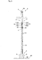
- Figs. 1 through 5 show a light-weight compact (handy type) self-standing accommodated elevating screen (hereafter referred to as a "elevating screen") 2 in which the screen (the size of the screen may be a size other than that shown in the figures) 1 can be accommodated and carried.
- the longitudinal direction of the casing 3 that is used to accommodate the elevating screen 2 shown in Fig. 1 i. e., the width direction of the screen
- the longitudinal direction perpendicular to the longitudinal direction of the abovementioned casing 3 (width direction of the screen) will be taken as the cross direction.
- the abovementioned elevating screen 2 comprises the abovementioned casing 3 which is used to take up and accommodate the abovementioned screen 1, and left and right linking mechanisms 5, 5 (see Fig. 5) which are disposed on the back the of the abovementioned screen 1, and whose upper ends are pivot-connected to the left and right ends of an upper-end supporting member 4 to which the upper end of the abovementioned screen 1 is connected.
- 6 shown in Fig. 5 is a cover member which can be freely opened and closed, and which is used to close the upper opening part 3K of the abovementioned casing 3; furthermore, 7 shown in Figs. 1 and 5 indicates a pair of front and rear handles which are used when the elevating screen 2 is carried.
- handles 7 are attached in manner that allows free swinging about the horizontal axis to supporting members 8, 8 that are screw-fastened to the abovementioned casing 3; furthermore, these handles 7 are constructed so that the handles 7 are free to swing between an accommodated attitude indicated by the solid line in Fig. 5 and a use attitude (indicated by the two-dot chain line) positioned above the casing 3. In some cases, however, these handles 7 may be omitted.
- the abovementioned elevating screen 2 is not limited to the construction shown in the figures; the shape, size and the like may be freely altered.
- the abovementioned casing 3 consists of a tubular casing main body 3A which is more or less C-shaped in cross section, and in which the abovementioned upper opening part 3K is formed, end part caps 3B, 3B which are used to close off the opening parts on the left and right ends of this casing main body 3A, and leg parts 3C, 3C which are more or less rectangular as seen in a plan view, and which are attached to the undersurface of the abovementioned casing main body in two specified locations on the left and right so that these leg parts 3C, 3C are free to rotate.
- the leg parts 3C, 3C are constructed so that the longitudinal direction of these leg parts can be freely switched between an accommodated (non-use) attitude (see Fig. 5) along the longitudinal, direction of the casing 3 and a use attitude (see Fig. 4) perpendicular to the longitudinal direction of the casing 3.
- the leg parts 3C, 3C may also be constructed so that these leg parts are detachable, or may be constructed as fixed leg parts that are fixed in the use attitude; furthermore, if the elevating screen 2 can be stably supported by the bottom surface of the casing 3, the leg parts 3C, 3C may be omitted.
- a horizontal plate 3D which is positioned slightly on the upper side is installed on the bottom part of the abovementioned casing main body 3A.
- This horizontal plate 3D is constructed so that this plate also serves as a base member for the fastening of the abovementioned linking mechanisms 5, 5 and the like; however, it would also be possible to attach a separate base member to the casing main body 3A.
- the abovementioned screen 1 is taken up on a tubular take-up pipe 9 used as a take-up member which is supported inside the abovementioned casing 3.
- the take-up pipe 9 is urged in the take-up direction (rotationally urged in one direction) by urging means such as a spring or the like (not shown in the figures).
- the upper end of the screen 1 can be connected to the upper-end supporting member 4 by engaging an engaging part 10 which is attached to the upper end of the abovementioned screen 1 with the abovementioned upper-end supporting member 4 (which has a left-right dimension that is more or less the same as the left-right width of the abovementioned screen 1); however, this connection may also be accomplished by some other method.
- a handle 4A which is used to raise the screen 1 is screw-fastened to the approximate cent raising-and-lowering arm portion of the abovementioned upper-end supporting member 4 (with respect to the left-right direction); however, this handle 4A may be omitted.
- the upper ends of left and right upper side arms 11, 11 which are made of metal (some other material may also be used as long as this material has more or less the same strength as a metal material) and which have a square-tube shape (this may also be a cylindrical shape or the like) are respectively pivot-connected via brackets 12 to the left and right end portions (the positions of these connections may also be located slightly toward the center from both end portions, as long as the positions are in the vicinity of the end portions) of the abovementioned upper-end supporting member 4, and the lower ends of left and right lower side arms 13, 13 which are made of metal (some other material may also be used as long as this material has more or less the same strength as a metal material) and which have a square-tube shape (this may also be a cylindrical shape or the like) are respectively pivot-connected to supporting plates 14, 14 which are fastened to the left and right end portions (the positions of these connections may also be located slightly toward the center
- the raising and lowering of the screen 1 can be accomplished with much greater stability; in some cases, however, the upper ends of the upper side arms 11, 11 may be pivot-connected in positions close to the center with respect to the left-right direction.
- the abovementioned left and right linking mechanisms 5, 5 that can be freely extended and retracted are constructed by pivot-connecting the upper ends of the abovementioned left and right upper side arms 11, 11 to the left and right end portions (these connections may also be made in positions that are located slightly toward the center from both end portions, as long as these positions are in the vicinity of the end portions) of the abovementioned upper-end supporting member 4 in a state in which the positions are shifted in the cross direction so that there is no overlapping in the left-right direction, pivot-connecting the lower ends of the abovementioned left and right lower side arms 13, 13 to the left and right end portions (these connections may also be made in positions that are located slightly toward the center from both end portions, as long as these positions are in the vicinity of the end portions) of the abovementioned base member 3D in a state in which the positions are shifted in the cross direction so that there is no overlapping in the left-right direction, and pivot-connecting the lower ends of the abovementioned
- the arms 11, 11, 13, 13 of the left and right linking mechanisms 5, 5 can be positioned in closer proximity to each other in the cross direction; moreover, the extension and retraction range of the linking mechanisms 5, 5 can be limited to a small range, which is also advantageous in terms of durability. Furthermore, as is also shown in Fig.
- each of] the abovementioned connecting members 15 consists of an upper-side engaging member 15A with a square shape which is fastened in place by being fit over the lower end of the corresponding upper side arm 11, a lower-side engaging member 15B with a square shape which is fastened in place by being fit over the lower end of the corresponding lower side arm 13, and a pin body 15C which constitutes a pivot-connecting part that connects the upper-side engaging member 15A and lower-side engaging member 15B so that these members are free to rotate.
- some other construction may also be used.
- gas springs (some other construction may also be used) 16, 16 used as urging means that urge the abovementioned lower side arms 13, 13 upward are attached between points located at more or less the centers (with respect to the longitudinal direction) of the lower side arms 13, 13 and brackets 17, 17 which are fastened to the base member 3D in positions that are located further toward the center (with respect to the left-right direction) than the abovementioned supporting plates 14, 14, so that the lowering of the screen 1 can be performed slowly, and so that the screen 1 can be positioned and held in an arbitrary height position.
- the screen 1 can be held in an arbitrary height position by balancing all of the factors such as the driving force of the abovementioned gas springs 1, 16, the frictional resistance in the pivot-connecting parts of the abovementioned connecting members 15, 15, the weight of the screen 1 and the like that is applied to the lower side arms 13, 13, the take-up driving force of the screen 1 and the like.
- slide members 20 each consisting of two split cases 18 and 19 are respectively attached to the abovementioned left and right lower side arms 13, 13, and these left and right slide members 20, 20 are connected on a vertical line S positions in more or less the central portion with respect to the cross direction and the left-right direction so that relative rotation of the members is possible, thus making it possible to extend and retract the left and right linking mechanisms 5, 5 smoothly and with good stability.
- slide members 20, 20 are attached to the lower side arms 13, 13; however, it would also be possible to attach the slide members 20, 20 to the upper side arms 11, 11, and the present invention could also be worked by attaching slide members 20, 20, 20, 20 to both the lower side arms 13, 13 and upper side arms 11, 11.
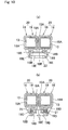
- one split case 18 [of each of the abovementioned slide members 20] consists of a C-shaped case main body 18A which covers approximately half of the outer circumference of the corresponding lower side arm 13, and a connecting plate part 18B which extends downward from the lower end portion of this case main body 18A.
- the other split case 19 consists of a C-shaped case main body 19A which covers approximately the remaining half of the outer circumference of the corresponding lower side arm 13, and a connecting plate part 19B which extends downward from the lower end portion of this case main body 19A.
- the two case main bodies 18A and 19A are anchored and fastened together by a recessed part 18C and a projecting part 19C which are respectively formed in the upper-end joining surfaces of the case main bodies 18A and 19A. Furthermore, the system is arranged so that the two split cases 18 and 19 are formed into an integral unit by screwing screws 21, 21 that are passed through a pair of left and right through-holes 18D, 18D formed in the connecting plate part 18B of one split case 18 into screw parts 19D, 19D formed in the connecting plate part 19B of the other split case 19; however, it would also be possible to form these split cases into an integral unit by means of an anchoring mechanism, adhesive agent or the like.
- a round recessed part 18E which can accommodate the round head part 22A of a pin 22 that is used to pivot-connect the two split cases 18 and 19 so that these split cases are free to rotate relative to each other is formed in the approximate center portion (with respect to the left-right direction) of the connecting plate part 18B of the abovementioned split case 18, and the connecting plate part 19B of the other split case 19 has an arch-form wall part 19E which checks the movement of the head part 22A of the abovementioned accommodated pin 22 in the axial direction by contacting this head part 22A, and which allows the shaft part 22B of the pin 22 to pass through, and supports this shaft part so that the pin is free to rotate.
- the relative rotation of the split cases 18 and 19 can be performed in a state in which there is little friction; however, a part other than this pin 22 may also be used. Accordingly, as a result of the split cases 18 and 19 that are pivot-connected via the pin 22 so that these split cases are free to rotate being fastened to the lower side arms 13, 13 by being fit over these arms so that the split cases are free to slide as shown in Figs.
- the left and right linking mechanisms 5, 5 can always be operated smoothly and stably when the screen 1 is switched from the use state to the accommodated state, since a state is obtained in which the lower side arms 13, 13 are connected by the slide members 20, 20 so that these lower side arms 13, 13 always show left-right symmetry at an arbitrary height position. Furthermore, as is shown in Figs. 4, 7 and 8 (c), when the lower side arms 13, 13 are in a horizontal attitude constituting the accommodated attitude, the abovementioned slide members 20, 20 are in a free state that allows movement in the horizontal direction.
- the elevating screen 2 When the abovementioned elevating screen 2 is to be raised and deployed, the elevating screen 2 is first moved to a specified position, and the abovementioned leg parts 3C, 3C are switched to the use attitude that is perpendicular to the longitudinal direction of the casing 3 as is shown in Figs. 1 through 4. From this state, the cover member 6 shown in Fig. 5 is move in the direction indicated by the arrow, so that the upper opening part 3K is opened. Next, the [elevating screen 2] can be deployed as shown in Figs. 1 through 3 by lifting the handle 4A to a specified height.
- the leg parts 3C, 3C are switched to the direction o length of the casing 3, so that contact of the leg parts 3C, 3C with other objects can be avoided while the elevating screen 2 is being moved.
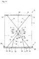
- the present invention can also be worked by attaching a screen deployment position regulating member 24 (which is used to check the upward movement of one of the two slide members 20, 20 attached to the abovementioned left and right lower side arms 13, 13 (the slide member positioned in front as seen from the back side of the screen 1 in Fig. 11) during the deployment of the abovementioned screen 1 by contacting this slide member 20) to the right lower side arm 1 in Fig. 11.
- a screen deployment position regulating member 24 which is used to check the upward movement of one of the two slide members 20, 20 attached to the abovementioned left and right lower side arms 13, 13 (the slide member positioned in front as seen from the back side of the screen 1 in Fig. 11) during the deployment of the abovementioned screen 1 by contacting this slide member 20
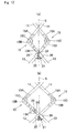
- the abovementioned screen deployment position regulating member 24 can be formed from a synthetic resin, metal, wood or the like. As is shown in Fig. 13, [this member 24] is formed as a more or less C-shaped member consisting of a plate-form main body part 24A which contacts the first side surface 13A (positioned on the front side in Fig.
- the screen deployment position regulating member 24 with a flat-plate shape or C shape in this manner is advantageous in that this allows the member 24 to be mounted even after the screen is assembled.
- a cylindrical or square-tube shape may also be used; [in short,] the screen deployment position regulating member 24 may have any [desired] shape.
- the abovementioned screen deployment position regulating member 24 is caused to contact the [corresponding] lower side arm 13 in a state in which the through-hole 24K of this member 24 is caused to coincide with a specified screw hole 13K (second screw hole from the bottom in Fig. 12 (b)) among a plurality of screw holes 13K (four screw holes in Fig. 12 (b)) formed in the lower side arm 13 at specified intervals; then, the screen deployment position regulating member 24 is fastened to the lower side arm 13 using a screw 25.
- the apparatus is constructed so that the maximum upper end position of he screen 1 can be altered to any of four positions, and so that [this maximum upper end position] can be altered to a fifth position that is even higher than the highest position among the abovementioned four positions by removing the screen deployment position regulating member 24.
- the present invention by forming the screw holes 13K as long slots along the longitudinal direction of the lower side arm 13, thus constructing the apparatus so that the screen deployment position regulating member 24 can be fastened in any position within these slots.
- the apparatus is devised so that the screen deployment position regulating member 24 is fastened to the lower side arm 13 using a screw 25.
- the linking mechanisms 5,5 perform an extension operation so that these linking mechanisms 5, 5 are further extended from the state shown in Fig. 12 (b), ad the upper end of the slide member 20 contacts the lower end of the screen deployment position regulating member as shown in Fig. 12 (a), so that the extension operation of the linking mechanisms 5, 5 is checked, thus making it possible to regulate the upper end position of the screen 1 in this position.
- the linking mechanisms disposed on the left and right extend or retract so that the screen can be supported smoothly and with good stability.
- this invention makes it possible to provide a self-standing manually operated elevating screen in which (for example) the pushing downward of the right end or left end (with respect to the transverse direction of the screen) of the upper-end supporting member of the screen in the deployed state (use state), or the pulling upward of the right end or left end (with respect to the transverse direction of the screen) of the upper-end supporting member of the screen in the accommodated state, can be checked by the slide members, so that the screen can be favorably used over a long period of time without causing any trouble such as deformation, damage or the like as a result of a large extension or retraction operation of only one of the linking mechanisms as in conventional techniques.
- the left and right arms can be caused to swing at the same swinging angle by the connected slide members, the left and right linking mechanisms can always be operated by a determined specified operation, so that the left and right linking mechanisms can be smoothly and stably extended or retracted in a state in which these mechanisms are linked as an integral unit.
- the construction can be simplified compared to cases in which a large apparatus such as a left-right balancing mechanism or the like is attached in order to cause stable extension and retraction of the left and right linking mechanisms. Accordingly, the present invention is advantageous in that this invention can prevent an increase in the size of the apparatus and an increase in the cost of the apparatus.
- the slide members which are in a free state can be maintained in specified positions by the stopper members when the screen is switched from the use attitude to the accommodated attitude. Accordingly, when the screen is switched from the accommodated attitude to the use attitude, there is no need to adjust the slide members to specified positions, i. e., to make individual positional adjustments of the slide members into a state in which the connected positions of the slide members are on a vertical line that is positioned more or less in the center with respect to the transverse direction of the screen. This is advantageous from the standpoint of use.
- the stopper members are formed by the attachment members that are used to attach one end of each urging means to the arms; as a result, the number of parts required can be reduced, which is advantageous from the standpoints of cost and assembly.
- the slide members each consist of two split cases, and the respective split cases are equipped with holding parts that are used to hold (in a manner that allows free rotation) the head parts disposed on both ends of a pin that is used to connect both split cases so that the split cases are free to rotate in relative terms.
- the split cases can easily be installed afterward on the arms of the assembled linking mechanisms; moreover, both split cases can be connected in a manner that allows free relative rotation in a state in which there is little frictional resistance. This is advantageous from the standpoint of assembly; moreover, this is also advantageous in that the operating force that is used to raise and lower the screen can be reduced.
- a screen deployment position regulating member which is used to check the upward movement of at least one of the two slide members attached to the left and right arms by contacting the upper end of this slide member during the deployment of the screen is attached to at least one of the arms, i. e., the left arm or right arm.
- the maximum deployment position of the screen can be altered, so that screens of different sizes can be assembled suing the same parts, thus making it possible to manufacture screens of different sizes without increasing the number of parts.
- the screen can be manufactured as a screen with a high commercial product vale that allows alteration of the use configuration (e. g., viewing in a lowered state or the like).
Landscapes
- Engineering & Computer Science (AREA)
- General Engineering & Computer Science (AREA)
- Physics & Mathematics (AREA)
- General Physics & Mathematics (AREA)
- Mechanical Engineering (AREA)
- Overhead Projectors And Projection Screens (AREA)
Abstract
Description
Claims (5)
- A self-standing manually operated elevating screen which is characterized in that:a take-up member to which one end of the screen is connected in order to take up the screen is attached to a base member in a state in which this take-up member is urged in the take-up direction;said base member and an upper-end supporting member to which the other end of said screen is connected are pivot-connected by linking mechanism formed by the pivot connection of upper side arms and lower side arms, with the linking mechanisms being separated into the left and right sides of the approximate center of the screen with respect to the transverse direction thereof;the pivot connection part of the upper side arm disposed on the left side in the transverse direction of said screen and the lower side arm disposed on the same side is disposed on the right side with respect to the transverse center portion of said upper-end supporting member, and the pivot connection part of the upper side arm disposed on the right side in the transverse direction of said screen and the lower side part disposed on the same side is disposed on the left side with respect to the transverse center portion of said upper-end supporting member;urging means for urging said lower side arms upward are installed between said lower side arms and said base member; andslide members which are freely slidable are attached either to said left and right upper side arms or said left and right lower side arms, or to both said left and right upper side arms and said left and right lower side arms, these left and right slide members being connected so that the slide members are capable of relative rotation on a vertical line positioned in the approximate center of said screen with respect to the transverse direction of said screen.
- The self-standing manually operated elevating screen according to claim 1, wherein said arms are provided with stopper members so that the stopper members come into contact with the left and right slide members attached to said left and right arms and prevent them from moving in the longitudinal direction of said arms in cases where the attitude of said arms is altered to a horizontal attitude are disposed on said arms.
- The self-standing manually operated elevating screen according to claim 2, wherein said stopper members are constituted by attachment members that are used to attach one end of said urging means to the arms.
- The self-standing manually operated elevating screen according to claim 1, wherein said slide members each comprise two split cases, and each of said split cases is provided with a holding part for rotatably holding head parts that are disposed on both ends of a pin that is used to connect the split cases so as to allow relative rotation of said split cases.
- The self-standing manually operated elevating screen according to any of claims 1 through 4, wherein a screen deployment position regulating member, which comes into contact with the upper end of at least one of the two slide members attached to said left and right arms and prevent the slide member(s) from moving upward during the deployment of said screen, is attached at least one of said left and right arms.
Applications Claiming Priority (5)
| Application Number | Priority Date | Filing Date | Title |
|---|---|---|---|
| JP2002148523 | 2002-05-23 | ||
| JP2002148523 | 2002-05-23 | ||
| JP2003062676 | 2003-03-10 | ||
| JP2003062676A JP4141864B2 (en) | 2002-05-23 | 2003-03-10 | Free-standing manual lifting screen |
| PCT/JP2003/005734 WO2003100519A1 (en) | 2002-05-23 | 2003-05-08 | Self-contained manual lifting screen |
Publications (2)
| Publication Number | Publication Date |
|---|---|
| EP1507167A1 true EP1507167A1 (en) | 2005-02-16 |
| EP1507167A4 EP1507167A4 (en) | 2007-08-15 |
Family
ID=29585962
Family Applications (1)
| Application Number | Title | Priority Date | Filing Date |
|---|---|---|---|
| EP03728042A Withdrawn EP1507167A4 (en) | 2002-05-23 | 2003-05-08 | Self-contained manual lifting screen |
Country Status (8)
| Country | Link |
|---|---|
| US (1) | US7203000B2 (en) |
| EP (1) | EP1507167A4 (en) |
| JP (1) | JP4141864B2 (en) |
| KR (1) | KR100787521B1 (en) |
| CN (1) | CN1656421A (en) |
| AU (1) | AU2003234786A1 (en) |
| TW (1) | TWI273336B (en) |
| WO (1) | WO2003100519A1 (en) |
Cited By (1)
| Publication number | Priority date | Publication date | Assignee | Title |
|---|---|---|---|---|
| EP1990681A3 (en) * | 2007-05-09 | 2009-06-24 | Bright Supply Corporation | Retractable frame of projection screen |
Families Citing this family (46)
| Publication number | Priority date | Publication date | Assignee | Title |
|---|---|---|---|---|
| JP2005345660A (en) * | 2004-06-02 | 2005-12-15 | Kinki Education Center:Kk | Folding screen |
| US20060080918A1 (en) * | 2004-09-17 | 2006-04-20 | Paul Clubbe | Screen assembly |
| US7963059B2 (en) * | 2004-12-01 | 2011-06-21 | Skyline Displays, Inc. | Tradeshow display formed of banner stands |
| JP4581935B2 (en) * | 2005-02-10 | 2010-11-17 | 株式会社オーエスエム | Freestanding lifting screen |
| TWD112308S1 (en) * | 2005-02-10 | 2006-08-01 | 歐英司工業股份有限公司 | Screen for projection |
| JP2006251757A (en) * | 2005-02-10 | 2006-09-21 | Os Kogyo Kk | Self-standing lifting screen |
| US8091605B1 (en) * | 2006-01-25 | 2012-01-10 | Jim Melhart Piano and Organ Company | Acoustic panel assembly |
| JP4464948B2 (en) * | 2006-10-13 | 2010-05-19 | 株式会社日立製作所 | Projection display system |
| TW200838536A (en) * | 2006-11-29 | 2008-10-01 | Takeda Pharmaceutical | Polymorphs of succinate salt of 2-[6-(3-amino-piperidin-1-yl)-3-methyl-2,4-dioxo-3,4-dihydro-2H-pyrimidin-1-ylmethy]-4-fluor-benzonitrile and methods of use therefor |
| USD568364S1 (en) * | 2006-12-06 | 2008-05-06 | Samsung Electronics Co., Ltd. | Portable LCD screen |
| KR100842820B1 (en) * | 2006-12-22 | 2008-07-01 | 중앙대학교 산학협력단 | Display device |
| TWM332038U (en) * | 2007-06-28 | 2008-05-11 | Tie-Han Wu | Sunshade curtain |
| USD596657S1 (en) * | 2007-11-05 | 2009-07-21 | Bright View Technologies, Inc. | Portable front projection screen |
| TW200921254A (en) * | 2007-11-06 | 2009-05-16 | Bright View Technologies Inc | Portable front projection screens |
| USD602973S1 (en) * | 2007-11-08 | 2009-10-27 | Bright View Technologies, Inc. | Portable front projection screen |
| CN201203751Y (en) * | 2008-05-16 | 2009-03-04 | 极品影视设备科技(深圳)有限公司 | Floor type projection screen |
| JP2010020270A (en) | 2008-06-09 | 2010-01-28 | Seiko Epson Corp | Screen |
| USD596219S1 (en) * | 2008-09-11 | 2009-07-14 | Seiko Epson Corporation | Screen unit for projector |
| CN101419389B (en) * | 2008-11-28 | 2010-06-09 | 广州美视晶莹银幕有限公司 | A portable self-supporting manual lifting screen |
| JP2011128338A (en) * | 2009-12-17 | 2011-06-30 | Seiko Epson Corp | Screen device |
| CN102162989B (en) | 2010-02-18 | 2013-04-10 | 精工爱普生株式会社 | Screen unit |
| KR101275241B1 (en) * | 2010-07-19 | 2013-06-14 | 박기한 | Appratus for unfolding and rolling the Electronic Paper Display |
| JP2012053378A (en) * | 2010-09-03 | 2012-03-15 | Seiko Epson Corp | Screen device |
| JP5609549B2 (en) * | 2010-11-02 | 2014-10-22 | 株式会社オーエスエム | Screen device |
| TWM403168U (en) * | 2010-12-06 | 2011-05-01 | Bright Supply Corp | Telescopic holder (5) display screen |
| US10724257B2 (en) | 2014-11-26 | 2020-07-28 | Control Dynamics, Inc. | Vertically raising safety rail with dual curtain assembly |
| US9745762B2 (en) * | 2014-11-26 | 2017-08-29 | Control Dynamics, Inc. | Vertically raising safety rail |
| US9480182B2 (en) * | 2014-12-30 | 2016-10-25 | King Slide Works Co., Ltd. | Cable management arm |
| CN107533277A (en) * | 2015-03-26 | 2018-01-02 | 艾维公司 | A kind of collapsible display device |
| JP7054386B2 (en) | 2015-10-21 | 2022-04-13 | アロヴィア,インコーポレイテッド | Improved voluntary pop-up display device |
| US10403184B2 (en) | 2016-12-22 | 2019-09-03 | Waldemar Veazie, IV | Freestanding exhibit display |
| CN108332013A (en) * | 2017-01-18 | 2018-07-27 | 生产材料集团有限责任公司 | The method of foldable space frame and installation space frame structure |
| USD827694S1 (en) * | 2017-06-06 | 2018-09-04 | Carbon System Verwaltungs Gmbh | Reflector for photography or cinematography |
| CN108279467A (en) * | 2017-12-26 | 2018-07-13 | 重庆市中光电显示技术有限公司 | The alignment means of polaroid |
| USD907686S1 (en) * | 2019-06-07 | 2021-01-12 | Carbon System Verwaltungs Gmbh | Parasol |
| CN110647003A (en) * | 2019-09-29 | 2020-01-03 | 深圳市火乐科技发展有限公司 | Curtain lifting mechanism and projection equipment |
| WO2021080223A1 (en) * | 2019-10-21 | 2021-04-29 | 최중선 | Roll screen device having wrinkle prevention function |
| KR102288505B1 (en) * | 2019-10-21 | 2021-08-10 | 최중선 | Roll Screen Device Comprising Wrinkle Free Function |
| FR3108126B1 (en) | 2020-03-10 | 2022-03-25 | Jamal Hoummada | Washer-dryer toilet seat frame assembly |
| WO2021218809A1 (en) * | 2020-04-26 | 2021-11-04 | 青岛海信激光显示股份有限公司 | Projection apparatus |
| USD939616S1 (en) * | 2020-11-29 | 2021-12-28 | Wuxi Donghui Video Equipment Co. Ltd. | Projection screen |
| USD942528S1 (en) * | 2021-01-08 | 2022-02-01 | Caipeng Zou | Backdrop holder |
| USD947929S1 (en) * | 2021-01-14 | 2022-04-05 | Shaoxing Shangyu Yixiang Digital Equipment Co., Ltd | Collapsible chroma key panel |
| USD972623S1 (en) * | 2021-05-24 | 2022-12-13 | ShenZhen Screen Workshop Technology Ltd. | Electric motorized floor screen |
| CN113701014B (en) * | 2021-05-29 | 2022-10-14 | 海南祺信智能科技有限公司 | Multi-vision networked video monitoring platform |
| JP7590804B2 (en) * | 2022-03-10 | 2024-11-27 | 株式会社Tmeic | Freestanding dustproof net |
Family Cites Families (16)
| Publication number | Priority date | Publication date | Assignee | Title |
|---|---|---|---|---|
| JPS6059247A (en) | 1983-09-07 | 1985-04-05 | 三井物産株式会社 | Culvert structure |
| JPS6059247U (en) * | 1983-09-09 | 1985-04-24 | 日本スクリ−ン株式会社 | projection screen device |
| AU102230S (en) * | 1986-04-14 | 1988-12-15 | Pankhurst Design & Developments Ltd | A projection screen |
| DE3910041A1 (en) | 1989-03-28 | 1990-10-04 | Heidelberger Druckmasch Ag | BOW FEEDER FOR SUPPLYING A BOW CURRENT ARRAY OF SINGLE BOWS TO A BOW-PROCESSING MACHINE |
| JPH0318529U (en) * | 1989-07-05 | 1991-02-22 | ||
| US5121977A (en) * | 1990-03-07 | 1992-06-16 | Weisgerber Robert C | Apparatus for raising and lowering the lower screen mask in a motion picture theater |
| JP2825692B2 (en) * | 1991-08-01 | 1998-11-18 | 三菱電機株式会社 | Screen structure |
| JPH05210168A (en) * | 1991-12-03 | 1993-08-20 | Victor Co Of Japan Ltd | Slide up screen and screen upper part mechanism |
| JP2719744B2 (en) * | 1992-07-30 | 1998-02-25 | 日本ビクター株式会社 | Slide up screen |
| JP3243037B2 (en) * | 1993-02-09 | 2002-01-07 | 株式会社ニチベイ | Projection screen |
| US5468040A (en) * | 1994-02-01 | 1995-11-21 | Peng Hsieh; Shih-Fang | Power-operated automobile sunshade |
| US5706130A (en) * | 1995-10-30 | 1998-01-06 | Rosen; John B. | Support assembly for a retractable device |
| JP3385207B2 (en) * | 1997-09-05 | 2003-03-10 | 泉株式会社 | Portable screen |
| JP3411515B2 (en) * | 1998-08-20 | 2003-06-03 | 泉株式会社 | Portable screen |
| US6191886B1 (en) * | 1998-08-24 | 2001-02-20 | Vutec Corp. | Video projection screen assembly |
| US6873458B1 (en) * | 2004-07-28 | 2005-03-29 | Hewlett-Packard Development Company, L.P. | Projection screen assembly |
-
2003
- 2003-03-10 JP JP2003062676A patent/JP4141864B2/en not_active Expired - Lifetime
- 2003-05-08 KR KR1020047016354A patent/KR100787521B1/en not_active Expired - Lifetime
- 2003-05-08 EP EP03728042A patent/EP1507167A4/en not_active Withdrawn
- 2003-05-08 US US10/511,449 patent/US7203000B2/en not_active Expired - Fee Related
- 2003-05-08 WO PCT/JP2003/005734 patent/WO2003100519A1/en not_active Ceased
- 2003-05-08 CN CNA038116871A patent/CN1656421A/en active Pending
- 2003-05-08 AU AU2003234786A patent/AU2003234786A1/en not_active Abandoned
- 2003-05-23 TW TW092114043A patent/TWI273336B/en not_active IP Right Cessation
Cited By (2)
| Publication number | Priority date | Publication date | Assignee | Title |
|---|---|---|---|---|
| EP1990681A3 (en) * | 2007-05-09 | 2009-06-24 | Bright Supply Corporation | Retractable frame of projection screen |
| EP2163948A3 (en) * | 2007-05-09 | 2011-11-23 | Bright Supply Corporation | Retractable frame of projection screen |
Also Published As
| Publication number | Publication date |
|---|---|
| TWI273336B (en) | 2007-02-11 |
| JP2004046078A (en) | 2004-02-12 |
| KR20050003366A (en) | 2005-01-10 |
| US7203000B2 (en) | 2007-04-10 |
| CN1656421A (en) | 2005-08-17 |
| AU2003234786A1 (en) | 2003-12-12 |
| WO2003100519A1 (en) | 2003-12-04 |
| TW200400409A (en) | 2004-01-01 |
| JP4141864B2 (en) | 2008-08-27 |
| EP1507167A4 (en) | 2007-08-15 |
| KR100787521B1 (en) | 2007-12-21 |
| US20050174638A1 (en) | 2005-08-11 |
Similar Documents
| Publication | Publication Date | Title |
|---|---|---|
| US7203000B2 (en) | Self-contained manual lifting screen | |
| EP2531886B1 (en) | Hand-held image stabilization and balancing system for cameras | |
| US6926375B2 (en) | Unit connecting mechanism and image display device | |
| US20040051010A1 (en) | Adjustable tripod assembly | |
| US6585214B1 (en) | Extended travel lift mechanism for a flat panel display | |
| JP4255384B2 (en) | Locking nesting member with posture response release | |
| US5590483A (en) | Implement attatching device for construction equipment | |
| JP3115185U (en) | Camera stand | |
| JPS6344272Y2 (en) | ||
| JP3948793B2 (en) | Tension rod | |
| JP4806753B2 (en) | Fall prevention device, storage furniture | |
| JP7335080B2 (en) | Canopy undulating structure and construction machinery to which it is applied | |
| JP2017202264A (en) | Wheelchair storage device | |
| CN223934734U (en) | Photography Assist Mobile Vehicle | |
| JP2002332191A (en) | Working machine with cab lift mechanism | |
| JP2510620B2 (en) | Garage door | |
| CN212902865U (en) | Fixed angle and telescopic support frame | |
| JP2539989Y2 (en) | Conversion equipment | |
| JPH04203194A (en) | Earth auger device | |
| CN112879750A (en) | Mobile photographic system | |
| JPH0626219Y2 (en) | Movable insertion side fence | |
| JPH0226284Y2 (en) | ||
| JPH03213276A (en) | Suspender for impact wrench | |
| JPH0643176B2 (en) | Seat frame up / down mechanism | |
| JPH0369731A (en) | Step fitting device in super-miniature shovel car |
Legal Events
| Date | Code | Title | Description |
|---|---|---|---|
| PUAI | Public reference made under article 153(3) epc to a published international application that has entered the european phase |
Free format text: ORIGINAL CODE: 0009012 |
|
| 17P | Request for examination filed |
Effective date: 20041208 |
|
| AK | Designated contracting states |
Kind code of ref document: A1 Designated state(s): AT BE BG CH CY CZ DE DK EE ES FI FR GB GR HU IE IT LI LU MC NL PT RO SE SI SK TR |
|
| AX | Request for extension of the european patent |
Extension state: AL LT LV MK |
|
| DAX | Request for extension of the european patent (deleted) | ||
| A4 | Supplementary search report drawn up and despatched |
Effective date: 20070718 |
|
| RIC1 | Information provided on ipc code assigned before grant |
Ipc: F16M 11/38 20060101ALI20070712BHEP Ipc: B66F 3/22 20060101ALI20070712BHEP Ipc: G03B 21/60 20060101ALI20070712BHEP Ipc: G03B 21/58 20060101AFI20031210BHEP |
|
| STAA | Information on the status of an ep patent application or granted ep patent |
Free format text: STATUS: THE APPLICATION HAS BEEN WITHDRAWN |
|
| 18W | Application withdrawn |
Effective date: 20080417 |