EP1507118A2 - Combustor dome assembly of a gas turbine engine having a free floating swirler - Google Patents
Combustor dome assembly of a gas turbine engine having a free floating swirler Download PDFInfo
- Publication number
- EP1507118A2 EP1507118A2 EP04254712A EP04254712A EP1507118A2 EP 1507118 A2 EP1507118 A2 EP 1507118A2 EP 04254712 A EP04254712 A EP 04254712A EP 04254712 A EP04254712 A EP 04254712A EP 1507118 A2 EP1507118 A2 EP 1507118A2
- Authority
- EP
- European Patent Office
- Prior art keywords
- swirler
- dome
- dome plate
- combustor
- cowl
- Prior art date
- Legal status (The legal status is an assumption and is not a legal conclusion. Google has not performed a legal analysis and makes no representation as to the accuracy of the status listed.)
- Withdrawn
Links
Images


Classifications
-
- F—MECHANICAL ENGINEERING; LIGHTING; HEATING; WEAPONS; BLASTING
- F23—COMBUSTION APPARATUS; COMBUSTION PROCESSES
- F23R—GENERATING COMBUSTION PRODUCTS OF HIGH PRESSURE OR HIGH VELOCITY, e.g. GAS-TURBINE COMBUSTION CHAMBERS
- F23R3/00—Continuous combustion chambers using liquid or gaseous fuel
- F23R3/02—Continuous combustion chambers using liquid or gaseous fuel characterised by the air-flow or gas-flow configuration
- F23R3/04—Air inlet arrangements
- F23R3/10—Air inlet arrangements for primary air
- F23R3/12—Air inlet arrangements for primary air inducing a vortex
- F23R3/14—Air inlet arrangements for primary air inducing a vortex by using swirl vanes
-
- F—MECHANICAL ENGINEERING; LIGHTING; HEATING; WEAPONS; BLASTING
- F23—COMBUSTION APPARATUS; COMBUSTION PROCESSES
- F23R—GENERATING COMBUSTION PRODUCTS OF HIGH PRESSURE OR HIGH VELOCITY, e.g. GAS-TURBINE COMBUSTION CHAMBERS
- F23R3/00—Continuous combustion chambers using liquid or gaseous fuel
- F23R3/02—Continuous combustion chambers using liquid or gaseous fuel characterised by the air-flow or gas-flow configuration
- F23R3/04—Air inlet arrangements
- F23R3/10—Air inlet arrangements for primary air
-
- F—MECHANICAL ENGINEERING; LIGHTING; HEATING; WEAPONS; BLASTING
- F23—COMBUSTION APPARATUS; COMBUSTION PROCESSES
- F23R—GENERATING COMBUSTION PRODUCTS OF HIGH PRESSURE OR HIGH VELOCITY, e.g. GAS-TURBINE COMBUSTION CHAMBERS
- F23R3/00—Continuous combustion chambers using liquid or gaseous fuel
- F23R3/42—Continuous combustion chambers using liquid or gaseous fuel characterised by the arrangement or form of the flame tubes or combustion chambers
- F23R3/60—Support structures; Attaching or mounting means
-
- F—MECHANICAL ENGINEERING; LIGHTING; HEATING; WEAPONS; BLASTING
- F23—COMBUSTION APPARATUS; COMBUSTION PROCESSES
- F23D—BURNERS
- F23D2211/00—Thermal dilatation prevention or compensation
Definitions
- the present invention relates generally to a combustor dome assembly for a gas turbine engine and, in particular, to a combustor dome assembly having a plurality of free floating swirlers which are retained in position between the dome plate and the inner and outer cowls so that each swirler is able to receive a fuel nozzle and be movable radially and axially in conjunction therewith.
- a dome portion in conjunction with inner and outer liners, serves to form the boundary of a combustion chamber.
- a mixture of fuel and air is ignited and burned in such combustion chamber so that the products thereof are able to interface with the blades of turbines and produce work through one or more shafts.
- the annular combustor dome also serves to position a plurality of mixers in a circumferential manner so that a fuel/air mixture is provided to the combustion chamber in a desired manner.
- Gas turbine combustors typically require a floating ferrule or primary swirler to prevent air leakage into the combustor and still allow for thermal growths of the combustor, combustion casing and fuel nozzles. This requirement has oftentimes been accomplished by brazing a secondary swirler or pad into the dome and using a welded retainer to hold the floating ferrule or primary swirler in place. It will be appreciated that the location of such components is critical to the combustor performance and functionality. Examples of such an arrangement are disclosed in U.S. Patent 6,427,435 to Patterson et al. and U.S. Patent 6,314,739 to Howell et al.
- one particular fuel/air mixer configuration includes a fuel nozzle which contains a pilot mixer therein. The fuel nozzle is then located within a main mixer. Accordingly, the size of the fuel nozzle and the corresponding swirler assembly associated therewith, has increased significantly from those previously utilized and thereby reduced the distance between adjacent swirler cups. Utilization of an annular dome plate having a greater diameter would serve to increase the weight of the engine and require modification of components interfacing therewith. Thus, the openings in the dome plate have been enlarged and thereby lessened the circumferential distance between adjacent openings.
- a combustor dome assembly in light of the foregoing, it would be desirable for a combustor dome assembly to be developed which accommodates minimum spacing between adjacent swirler cups. It would also be desirable to simplify such a combustor dome assembly and reduce the amount of components needed while maintaining its intended functionality. Improvements in the area of producibility, maintainability and serviceability are likewise desired.
- a combustor dome assembly for a gas turbine engine is disclosed as having a longitudinal centerline axis extending therethrough.
- the combustor assembly includes: an annular dome plate having an inner portion, an outer portion, a forward surface and a plurality of circumferentially spaced openings formed therein, wherein a radial section is defined between adjacent openings; an annular outer cowl connected to the outer portion of the dome plate; an annular inner cowl connected to the inner portion of the dome plate; and, a swirler located between the forward surface of the dome plate and the inner and outer cowls in substantial alignment with each of the openings in the dome plate.
- Each swirler further includes a forward portion and an aft portion and is retained by at least one tab member located upstream thereof so as to be movable in a radial and axial direction.
- annular cowl for a gas turbine engine combustor having a longitudinal centerline axis therethrough where the combustor includes an annular dome plate having an inner portion, an outer portion, a forward surface and a plurality of circumferentially spaced openings formed therein.
- the cowl includes a downstream end connected to one of the inner and outer portions of the dome plate, an upstream end positioned upstream of the forward surface for the dome plate, and a plurality of circumferentially spaced tab members extending from an inner surface of the upstream end.
- the tab members serve to retain a corresponding swirler between the cowl and the dome plate in a free floating manner while maintaining substantial alignment with one of the openings in the dome plate.
- Fig. 1 depicts an exemplary gas turbine engine combustor 10 having a longitudinal centerline axis 12 extending therethrough.
- Combustor 10 includes a combustion chamber 14 defined by an outer liner 16, an inner liner 18, and a dome plate 20 located at an upstream end thereof.
- a plurality of fuel/air mixers 22 are circumferentially spaced within dome plate 20 so as to introduce a mixture of fuel and air into combustion chamber 14, where it is ignited by an igniter (not shown) and combustion gases are formed which are utilized to drive one or more turbines downstream thereof.
- each air/fuel mixer 22 preferably includes a fuel nozzle 24, a swirler 26, and a deflector plate 28.
- dome plate 20 is annular in configuration and includes an inner portion 30, an outer portion 32, a forward surface 34 and a plurality of circumferentially spaced openings 36 formed therein (see Fig. 5). Accordingly, a radial section 37 is defined between each adjacent opening 36 in dome plate 20.
- An annular outer cowl 38 is preferably affixed to outer portion 32 of dome plate 20 at a downstream end 39, as well as to outer liner 16, by means of a plurality of connections 40 (e.g., bolts and nuts).
- an annular inner cowl 44 is preferably affixed to inner portion 30 of dome plate 20 at a downstream end 45, as well as to inner liner 18, by means of a plurality of connections 46 (bolts and nuts).
- Each swirler 26 is located between forward surface 34 of dome plate 20 and upstream ends 47 and 49 of outer and inner cowls 38 and 44, respectively, so as to be in substantial alignment with an opening 36 in dome plate 20. Further, each swirler 26 preferably includes a forward portion 50 and an aft portion 52. It will be appreciated that swirlers 26 are not fixed or attached to any other component of air/fuel mixer 22, but are permitted to float freely in both a radial and axial direction with respect to a centerline axis 53 through each opening 36. Each swirler 26 preferably includes vanes 48 therein which are oriented to provide swirl in a substantially radial direction with respect to centerline axis 53.
- first tab member 54 and a second tab member 56 are located upstream of each swirler 26 at approximately a radially outer position and a radially inner position, respectively.
- first tab members 54 are preferably associated with a surface 35 of outer cowl 38.
- second tab members 56 are preferably associated with a surface 43 of inner cowl 44.
- first and second tab members 54 and 56 may be attached to their respective cowl (e.g., via brazing or the like) and/or formed integrally therewith (via forging and machining operations). It will be appreciated that the presence of tab members 54 and 56 and the spacing therebetween functions to detune cowls 38 and 44, respectively, and thereby improve the frequency margin thereof.
- first tab members 54 and second tab members 56 preferably include an axial surface 62 and 64, respectively, associated therewith for accommodating a predetermined amount of radial growth and movement by swirler forward portion 50 therebetween.
- First and second tab members 54 and 56 also preferably include a radial surface 66 and 68, respectively, associated therewith and spaced from dome plate forward surface 34 a predetermined amount for accommodating axial growth and movement by swirler 26. It will be appreciated that the amount of axial movement is limited to prevent swirlers 26 from wedging themselves in a position which is misaligned with their respective dome plate opening 36.
- swirler forward portion 50 preferably includes a radial flange 70 which moves between axial surfaces 62 and 64 of first and second tabs 54 and 56 and interfaces with radial surfaces 66 and 68.
- Swirler forward portion 50 also preferably includes an axial section 72 which receives fuel nozzle 24 in an inner surface 73 thereof.
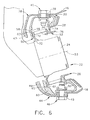
- tab members 58 may be connected to dome plate outer portion 32, outer liner 16, and outer cowl downstream end 39 via connectors 40.
- tab members 60 may be connected to dome plate inner portion 30, inner liner 18, and inner cowl downstream end 45 via connectors 46.
- Tab members 58 and 60 each preferably include an axial surface 59 and 61, respectively, as well as a radial surface 63 and 65, which function as described above with respect to tab members 54 and 56.
- Swirler aft portion 52 preferably includes a flange 74 which is able to slide radially along a boss portion 75 of dome plate forward surface 34.
- a lip 76 is connected to flange 74 and is preferably oriented substantially perpendicular to flange 74 so that it is substantially parallel to centerline axis 53. It will be noted that lip 76 extends aft of dome plate forward surface 34 so that it interfaces with deflector plate 28 to limit radial movement of swirler aft portion 52.
- Fuel nozzle 24 is preferably of the type disclosed in U.S. Patent 6,381,964 to Pritchard, Jr. et al., which is hereby incorporated by reference. It will be appreciated that fuel nozzle 24 is larger than typical fuel nozzles and therefore requires larger openings in dome plate 20. It will be understood that one feature of free floating swirlers 26 is the ability to move with fuel nozzles 24 during operation of the gas turbine engine. Further, swirlers 26 are able to be adjusted when fuel nozzles 24 are inserted therein. In this regard, tab members 54 and 56 are configured to provide an adequate clearance with fuel nozzles 24.
Landscapes
- Engineering & Computer Science (AREA)
- Chemical & Material Sciences (AREA)
- Combustion & Propulsion (AREA)
- Mechanical Engineering (AREA)
- General Engineering & Computer Science (AREA)
- Turbine Rotor Nozzle Sealing (AREA)
- Cyclones (AREA)
Abstract
Description
- The present invention relates generally to a combustor dome assembly for a gas turbine engine and, in particular, to a combustor dome assembly having a plurality of free floating swirlers which are retained in position between the dome plate and the inner and outer cowls so that each swirler is able to receive a fuel nozzle and be movable radially and axially in conjunction therewith.
- It is well known within the combustor art of gas turbine engines that a dome portion, in conjunction with inner and outer liners, serves to form the boundary of a combustion chamber. A mixture of fuel and air is ignited and burned in such combustion chamber so that the products thereof are able to interface with the blades of turbines and produce work through one or more shafts. The annular combustor dome also serves to position a plurality of mixers in a circumferential manner so that a fuel/air mixture is provided to the combustion chamber in a desired manner.
- Gas turbine combustors typically require a floating ferrule or primary swirler to prevent air leakage into the combustor and still allow for thermal growths of the combustor, combustion casing and fuel nozzles. This requirement has oftentimes been accomplished by brazing a secondary swirler or pad into the dome and using a welded retainer to hold the floating ferrule or primary swirler in place. It will be appreciated that the location of such components is critical to the combustor performance and functionality. Examples of such an arrangement are disclosed in U.S. Patent 6,427,435 to Patterson et al. and U.S. Patent 6,314,739 to Howell et al.
- While the typical combustor arrangement has adequate space between swirler cups to incorporate features to enhance the spectacle plate structure (e.g., the addition of ribs, cooling holes and the like), certain geometric restrictions have been introduced by current combustor designs which run lean so as to minimize emissions. As disclosed in U.S. Patent 6,381,964 to Pritchard, Jr. et al., one particular fuel/air mixer configuration includes a fuel nozzle which contains a pilot mixer therein. The fuel nozzle is then located within a main mixer. Accordingly, the size of the fuel nozzle and the corresponding swirler assembly associated therewith, has increased significantly from those previously utilized and thereby reduced the distance between adjacent swirler cups. Utilization of an annular dome plate having a greater diameter would serve to increase the weight of the engine and require modification of components interfacing therewith. Thus, the openings in the dome plate have been enlarged and thereby lessened the circumferential distance between adjacent openings.
- Thus, in light of the foregoing, it would be desirable for a combustor dome assembly to be developed which accommodates minimum spacing between adjacent swirler cups. It would also be desirable to simplify such a combustor dome assembly and reduce the amount of components needed while maintaining its intended functionality. Improvements in the area of producibility, maintainability and serviceability are likewise desired.
- In a first exemplary embodiment of the invention, a combustor dome assembly for a gas turbine engine is disclosed as having a longitudinal centerline axis extending therethrough. The combustor assembly includes: an annular dome plate having an inner portion, an outer portion, a forward surface and a plurality of circumferentially spaced openings formed therein, wherein a radial section is defined between adjacent openings; an annular outer cowl connected to the outer portion of the dome plate; an annular inner cowl connected to the inner portion of the dome plate; and, a swirler located between the forward surface of the dome plate and the inner and outer cowls in substantial alignment with each of the openings in the dome plate. Each swirler further includes a forward portion and an aft portion and is retained by at least one tab member located upstream thereof so as to be movable in a radial and axial direction.
- In a second exemplary embodiment of the invention, an annular cowl for a gas turbine engine combustor having a longitudinal centerline axis therethrough is disclosed, where the combustor includes an annular dome plate having an inner portion, an outer portion, a forward surface and a plurality of circumferentially spaced openings formed therein. The cowl includes a downstream end connected to one of the inner and outer portions of the dome plate, an upstream end positioned upstream of the forward surface for the dome plate, and a plurality of circumferentially spaced tab members extending from an inner surface of the upstream end. The tab members serve to retain a corresponding swirler between the cowl and the dome plate in a free floating manner while maintaining substantial alignment with one of the openings in the dome plate.
- Embodiments of the invention will now be described, by way of example, with reference to the accompanying drawings, in which:
- Fig. 1 is a cross-sectional view of a gas turbine engine combustor including a combustor dome assembly of the present invention;
- Fig. 2 is an enlarged, partial cross-sectional view of the combustor dome assembly depicted in Fig. 1;
- Fig. 3 is an enlarged, partial aft view of the inner and outer cowls of the combustor dome assembly depicted in Figs. 1 and 2;
- Fig. 4 is an enlarged, partial aft view of the swirlers and the inner and outer cowls of the combustor dome assembly depicted in Figs. 1 and 2;
- Fig. 5 is an enlarged, partial aft view of the dome plate for the combustor dome assembly depicted in Figs. 1 and 2; and,
- Fig. 6 is an enlarged, partial cross-sectional view of an alternative embodiment for the combustor dome assembly of the present invention.
-
- Referring now to the drawings in detail, wherein identical numerals indicate the same elements throughout the figures, Fig. 1 depicts an exemplary gas
turbine engine combustor 10 having alongitudinal centerline axis 12 extending therethrough.Combustor 10 includes acombustion chamber 14 defined by anouter liner 16, aninner liner 18, and adome plate 20 located at an upstream end thereof. It will be understood that a plurality of fuel/air mixers 22 are circumferentially spaced withindome plate 20 so as to introduce a mixture of fuel and air intocombustion chamber 14, where it is ignited by an igniter (not shown) and combustion gases are formed which are utilized to drive one or more turbines downstream thereof. More specifically, each air/fuel mixer 22 preferably includes afuel nozzle 24, aswirler 26, and adeflector plate 28. - More specifically, it will be understood that
dome plate 20 is annular in configuration and includes aninner portion 30, anouter portion 32, aforward surface 34 and a plurality of circumferentially spacedopenings 36 formed therein (see Fig. 5). Accordingly, aradial section 37 is defined between eachadjacent opening 36 indome plate 20. An annularouter cowl 38 is preferably affixed toouter portion 32 ofdome plate 20 at adownstream end 39, as well as toouter liner 16, by means of a plurality of connections 40 (e.g., bolts and nuts). Similarly, an annularinner cowl 44 is preferably affixed toinner portion 30 ofdome plate 20 at adownstream end 45, as well as toinner liner 18, by means of a plurality of connections 46 (bolts and nuts). - Each
swirler 26 is located betweenforward surface 34 ofdome plate 20 and upstreamends inner cowls opening 36 indome plate 20. Further, eachswirler 26 preferably includes aforward portion 50 and anaft portion 52. It will be appreciated thatswirlers 26 are not fixed or attached to any other component of air/fuel mixer 22, but are permitted to float freely in both a radial and axial direction with respect to acenterline axis 53 through eachopening 36. Eachswirler 26 preferably includesvanes 48 therein which are oriented to provide swirl in a substantially radial direction with respect tocenterline axis 53. - It is desirable, however, that
swirlers 26 be retained in position betweendome plate 20 and cowl upstream ends 47 and 49 so thatfuel nozzles 24 may be desirably received therein. Accordingly, at least one tab member is provided upstream of eachswirler 26 to restrict radial and axial movement thereof to a predetermined amount. Preferably, it will be noted that afirst tab member 54 and asecond tab member 56 are located upstream of eachswirler 26 at approximately a radially outer position and a radially inner position, respectively. As seen in Figs. 1-4,first tab members 54 are preferably associated with asurface 35 ofouter cowl 38. Likewise,second tab members 56 are preferably associated with asurface 43 ofinner cowl 44. In such case, first andsecond tab members tab members cowls - As best seen in Figs. 2 and 3,
first tab members 54 andsecond tab members 56 preferably include anaxial surface forward portion 50 therebetween. First andsecond tab members radial surface swirler 26. It will be appreciated that the amount of axial movement is limited to preventswirlers 26 from wedging themselves in a position which is misaligned with their respective dome plate opening 36. In this regard, it will be seen that swirlerforward portion 50 preferably includes aradial flange 70 which moves betweenaxial surfaces second tabs radial surfaces forward portion 50 also preferably includes anaxial section 72 which receivesfuel nozzle 24 in aninner surface 73 thereof. - Alternatively, as seen in Fig. 6,
separate tab members 58 may be connected to dome plateouter portion 32,outer liner 16, and outer cowl downstreamend 39 viaconnectors 40. Similarly,tab members 60 may be connected to dome plateinner portion 30,inner liner 18, and inner cowl downstreamend 45 viaconnectors 46.Tab members axial surface radial surface tab members -
Swirler aft portion 52 preferably includes aflange 74 which is able to slide radially along aboss portion 75 of dome plateforward surface 34. Alip 76 is connected toflange 74 and is preferably oriented substantially perpendicular to flange 74 so that it is substantially parallel tocenterline axis 53. It will be noted thatlip 76 extends aft of dome plateforward surface 34 so that it interfaces withdeflector plate 28 to limit radial movement ofswirler aft portion 52. -
Fuel nozzle 24 is preferably of the type disclosed in U.S. Patent 6,381,964 to Pritchard, Jr. et al., which is hereby incorporated by reference. It will be appreciated thatfuel nozzle 24 is larger than typical fuel nozzles and therefore requires larger openings indome plate 20. It will be understood that one feature of freefloating swirlers 26 is the ability to move withfuel nozzles 24 during operation of the gas turbine engine. Further,swirlers 26 are able to be adjusted whenfuel nozzles 24 are inserted therein. In this regard,tab members fuel nozzles 24. - Other advantages are also associated with the combustor dome assembly of the present invention. For example, producibility of the combustor dome assembly is improved since a braze and weld operation at each swirler is eliminated. Moreover, inspection of the braze joint connecting
deflector plates 28 todome plate 20 is enhanced. Since the number of components in the combustor dome assembly is reduced, maintainability ofswirlers 26 is improved. Becauseswirlers 26 can be removed simply by unbolting one ofcowls connectors
Claims (10)
- A combustor dome assembly (10) for a gas turbine engine having a longitudinal centerline axis (12) extending therethrough, comprising:wherein each said swirler (26) is retained in a manner so as to be movable in a radial and axial direction.(a) an annular dome plate (20) having an inner portion (30), an outer portion (32), a forward surface (34) and a plurality of circumferentially spaced openings (36) formed therein, wherein a radial section (37) is defined between each adjacent opening (36);(b) an annular outer cowl (38) connected to said outer portion (32) of said dome plate (20);(c) an annular inner cowl (44) connected to said inner portion (30) of said dome plate (20); and,(d) a swirler (26) located between said forward surface (34) of said dome plate (20) and said inner and outer cowls (44,38) in substantial alignment with each of said openings (36) in said dome plate (20), said swirler (26) including a forward portion (50) and an aft portion (52);
- The combustor dome assembly (10) of claim 1, further comprising at least one tab (54/58,56/60) located upstream of each said swirler (26) for retaining said swirler (26) with respect to said dome plate (20).
- The combustor dome assembly (10) of claim 1, further comprising a first tab (54/58) and a second tab (56/60) located upstream of each said swirler (26) for retaining said swirler (26) with respect to said dome plate (20).
- The combustor dome assembly (10) of claim 3, wherein said first tabs (54/58) are connected to said outer cowl (38) and said second tabs (56/60) are connected to said inner cowl (44).
- The combustor dome assembly (10) of claim 3, said first and second tabs (54/58,56/60) each including an axial surface (62/59,64/61) associated therewith for accommodating a predetermined amount of radial growth and movement by each said swirler forward portion (50) therebetween.
- The combustor dome assembly (10) of claim 3, said first and second tabs (54/58,56/60) each including an radial surface (66/63,68/65) associated therewith and spaced from said dome plate forward surface (34) for accommodating a predetermined amount of axial growth and movement by each said swirler (26).
- The combustor dome assembly (10) of claim 1, said swirler aft portion (52) including a flange (74) which moves radially along said forward surface (34) of said dome plate (20).
- The combustor dome assembly (10) of claim 3, said swirler forward portion (50) including a radial section (70) which moves between said first and second tabs (54/58,56/60) and an axial section (72) for receiving a fuel nozzle (24).
- An annular cowl (44/38) for a gas turbine engine combustor (10) having a longitudinal centerline axis (12) therethrough, said combustor (10) including an annular dome plate (20) having an inner portion (30), an outer portion (32), a forward surface (34) and a plurality of circumferentially spaced openings (36) formed therein, comprising:wherein said tab members (56/54) serve to retain a corresponding swirler (46) between said cowl (44/38) and said dome plate (20) in a free floating manner while maintaining substantial alignment with one of said openings (36) in said dome plate (20).(a) a downstream end (45/39) connected to one of said inner and outer portions (30/32) of said dome plate (20);(b) an upstream end (49/47) positioned upstream of said forward surface (34) for said dome plate (20); and,(c) a plurality of circumferentially spaced tab members (56/54) extending from an inner surface (43/35) of said upstream end (49/47);
- The cowl (44/38) of claim 9, each said tab member (56/54) further comprising:(a) an axial surface (64/62) which serves to limit radial growth and movement of the swirler (26); and,(b) a radial surface (68/66) spaced a predetermined amount from said dome plate forward surface (34) which serves to limit axial growth and movement of the swirler (26).
Applications Claiming Priority (2)
| Application Number | Priority Date | Filing Date | Title |
|---|---|---|---|
| US638597 | 1984-08-07 | ||
| US10/638,597 US7062920B2 (en) | 2003-08-11 | 2003-08-11 | Combustor dome assembly of a gas turbine engine having a free floating swirler |
Publications (2)
| Publication Number | Publication Date |
|---|---|
| EP1507118A2 true EP1507118A2 (en) | 2005-02-16 |
| EP1507118A3 EP1507118A3 (en) | 2013-01-16 |
Family
ID=33565215
Family Applications (1)
| Application Number | Title | Priority Date | Filing Date |
|---|---|---|---|
| EP04254712A Withdrawn EP1507118A3 (en) | 2003-08-11 | 2004-08-05 | Combustor dome assembly of a gas turbine engine having a free floating swirler |
Country Status (4)
| Country | Link |
|---|---|
| US (1) | US7062920B2 (en) |
| EP (1) | EP1507118A3 (en) |
| JP (1) | JP4559796B2 (en) |
| CN (1) | CN100520185C (en) |
Cited By (2)
| Publication number | Priority date | Publication date | Assignee | Title |
|---|---|---|---|---|
| US20120186259A1 (en) * | 2011-01-26 | 2012-07-26 | United Technologies Corporation | Fuel injector assembly |
| US20160201915A1 (en) * | 2013-08-30 | 2016-07-14 | United Technologies Corporation | Swirler mount interface for gas turbine engine combustor |
Families Citing this family (45)
| Publication number | Priority date | Publication date | Assignee | Title |
|---|---|---|---|---|
| US7581402B2 (en) * | 2005-02-08 | 2009-09-01 | Siemens Energy, Inc. | Turbine engine combustor with bolted swirlers |
| FR2881813B1 (en) * | 2005-02-09 | 2011-04-08 | Snecma Moteurs | TURBOMACHINE COMBUSTION CHAMBER FAIRING |
| US7415826B2 (en) * | 2005-07-25 | 2008-08-26 | General Electric Company | Free floating mixer assembly for combustor of a gas turbine engine |
| FR2897144B1 (en) * | 2006-02-08 | 2008-05-02 | Snecma Sa | COMBUSTION CHAMBER FOR TURBOMACHINE WITH TANGENTIAL SLOTS |
| FR2897145B1 (en) * | 2006-02-08 | 2013-01-18 | Snecma | ANNULAR COMBUSTION CHAMBER FOR TURBOMACHINE WITH ALTERNATE FIXINGS. |
| US7849682B2 (en) * | 2006-08-31 | 2010-12-14 | Caterpillar Inc | Exhaust treatment device having a fuel powered burner |
| US7765809B2 (en) * | 2006-11-10 | 2010-08-03 | General Electric Company | Combustor dome and methods of assembling such |
| US7856826B2 (en) * | 2006-11-10 | 2010-12-28 | General Electric Company | Combustor dome mixer retaining means |
| FR2910115B1 (en) * | 2006-12-19 | 2012-11-16 | Snecma | DEFLECTOR FOR BOTTOM OF COMBUSTION CHAMBER, COMBUSTION CHAMBER WHERE IT IS EQUIPPED AND TURBOREACTOR COMPRISING THEM |
| US20090255120A1 (en) * | 2008-04-11 | 2009-10-15 | General Electric Company | Method of assembling a fuel nozzle |
| US8806871B2 (en) * | 2008-04-11 | 2014-08-19 | General Electric Company | Fuel nozzle |
| US8061142B2 (en) * | 2008-04-11 | 2011-11-22 | General Electric Company | Mixer for a combustor |
| US20100162714A1 (en) * | 2008-12-31 | 2010-07-01 | Edward Claude Rice | Fuel nozzle with swirler vanes |
| US8689563B2 (en) * | 2009-07-13 | 2014-04-08 | United Technologies Corporation | Fuel nozzle guide plate mistake proofing |
| US8375548B2 (en) * | 2009-10-07 | 2013-02-19 | Pratt & Whitney Canada Corp. | Fuel nozzle and method of repair |
| US8726669B2 (en) | 2011-06-30 | 2014-05-20 | General Electric Company | Combustor dome with combined deflector/mixer retainer |
| US8893382B2 (en) * | 2011-09-30 | 2014-11-25 | General Electric Company | Combustion system and method of assembling the same |
| US10088166B2 (en) | 2013-07-15 | 2018-10-02 | United Technologies Corporation | Swirler mount interface for gas turbine engine combustor |
| CA2931246C (en) | 2013-11-27 | 2019-09-24 | General Electric Company | Fuel nozzle with fluid lock and purge apparatus |
| FR3015639B1 (en) * | 2013-12-20 | 2018-08-31 | Safran Aircraft Engines | COMBUSTION CHAMBER IN A TURBOMACHINE |
| EP3087321B1 (en) | 2013-12-23 | 2020-03-25 | General Electric Company | Fuel nozzle structure for air-assisted fuel injection |
| JP6695801B2 (en) | 2013-12-23 | 2020-05-20 | ゼネラル・エレクトリック・カンパニイ | Fuel nozzle with flexible support structure |
| GB201408690D0 (en) | 2014-05-16 | 2014-07-02 | Rolls Royce Plc | A combustion chamber arrangement |
| GB201613110D0 (en) | 2016-07-29 | 2016-09-14 | Rolls Royce Plc | A combustion chamber |
| US10393381B2 (en) | 2017-01-27 | 2019-08-27 | General Electric Company | Unitary flow path structure |
| US10371383B2 (en) | 2017-01-27 | 2019-08-06 | General Electric Company | Unitary flow path structure |
| US10378770B2 (en) | 2017-01-27 | 2019-08-13 | General Electric Company | Unitary flow path structure |
| US11111858B2 (en) | 2017-01-27 | 2021-09-07 | General Electric Company | Cool core gas turbine engine |
| US10816199B2 (en) | 2017-01-27 | 2020-10-27 | General Electric Company | Combustor heat shield and attachment features |
| US10253643B2 (en) | 2017-02-07 | 2019-04-09 | General Electric Company | Airfoil fluid curtain to mitigate or prevent flow path leakage |
| US10370990B2 (en) | 2017-02-23 | 2019-08-06 | General Electric Company | Flow path assembly with pin supported nozzle airfoils |
| US10253641B2 (en) | 2017-02-23 | 2019-04-09 | General Electric Company | Methods and assemblies for attaching airfoils within a flow path |
| US10378373B2 (en) | 2017-02-23 | 2019-08-13 | General Electric Company | Flow path assembly with airfoils inserted through flow path boundary |
| US10247019B2 (en) | 2017-02-23 | 2019-04-02 | General Electric Company | Methods and features for positioning a flow path inner boundary within a flow path assembly |
| US10385776B2 (en) | 2017-02-23 | 2019-08-20 | General Electric Company | Methods for assembling a unitary flow path structure |
| US10385709B2 (en) | 2017-02-23 | 2019-08-20 | General Electric Company | Methods and features for positioning a flow path assembly within a gas turbine engine |
| US10859269B2 (en) * | 2017-03-31 | 2020-12-08 | Delavan Inc. | Fuel injectors for multipoint arrays |
| US10385731B2 (en) | 2017-06-12 | 2019-08-20 | General Electric Company | CTE matching hanger support for CMC structures |
| US11402097B2 (en) | 2018-01-03 | 2022-08-02 | General Electric Company | Combustor assembly for a turbine engine |
| US11268394B2 (en) | 2020-03-13 | 2022-03-08 | General Electric Company | Nozzle assembly with alternating inserted vanes for a turbine engine |
| CN113819489B (en) * | 2020-06-19 | 2023-02-28 | 中国航发商用航空发动机有限责任公司 | Gas turbine, combustion chamber and swirler assembly thereof |
| US11428160B2 (en) | 2020-12-31 | 2022-08-30 | General Electric Company | Gas turbine engine with interdigitated turbine and gear assembly |
| GB2611115B (en) | 2021-09-23 | 2024-10-09 | Gen Electric | Floating primary vane swirler |
| EP4202304B1 (en) | 2021-12-21 | 2025-02-26 | General Electric Company | Turbine engine with fuel nozzle and swirler |
| US20250290636A1 (en) * | 2024-03-14 | 2025-09-18 | General Electric Company | Gas turbine engine combustor having ceramic matrix composite (cmc) liners and cmc dome |
Citations (3)
| Publication number | Priority date | Publication date | Assignee | Title |
|---|---|---|---|---|
| US5916142A (en) | 1996-10-21 | 1999-06-29 | General Electric Company | Self-aligning swirler with ball joint |
| EP1186832A2 (en) * | 2000-09-08 | 2002-03-13 | General Electric Company | Fuel nozzle assembly for reduced exhaust emissions |
| US6381964B1 (en) | 2000-09-29 | 2002-05-07 | General Electric Company | Multiple annular combustion chamber swirler having atomizing pilot |
Family Cites Families (13)
| Publication number | Priority date | Publication date | Assignee | Title |
|---|---|---|---|---|
| US3703259A (en) * | 1971-05-03 | 1972-11-21 | Gen Electric | Air blast fuel atomizer |
| US4763482A (en) | 1987-01-02 | 1988-08-16 | General Electric Company | Swirler arrangement for combustor of gas turbine engine |
| FR2639095B1 (en) * | 1988-11-17 | 1990-12-21 | Snecma | COMBUSTION CHAMBER OF A TURBOMACHINE WITH FLOATING MOUNTS PREVAPORIZATION BOWLS |
| US5865024A (en) * | 1997-01-14 | 1999-02-02 | General Electric Company | Dual fuel mixer for gas turbine combustor |
| GB2328011A (en) * | 1997-08-05 | 1999-02-10 | Europ Gas Turbines Ltd | Combustor for gas or liquid fuelled turbine |
| US6571559B1 (en) | 1998-04-03 | 2003-06-03 | General Electric Company | Anti-carboning fuel-air mixer for a gas turbine engine combustor |
| US6453671B1 (en) | 2000-01-13 | 2002-09-24 | General Electric Company | Combustor swirler assembly |
| US6314739B1 (en) | 2000-01-13 | 2001-11-13 | General Electric Company | Brazeless combustor dome assembly |
| US6427435B1 (en) | 2000-05-20 | 2002-08-06 | General Electric Company | Retainer segment for swirler assembly |
| US6363726B1 (en) | 2000-09-29 | 2002-04-02 | General Electric Company | Mixer having multiple swirlers |
| US6484489B1 (en) | 2001-05-31 | 2002-11-26 | General Electric Company | Method and apparatus for mixing fuel to decrease combustor emissions |
| US6418726B1 (en) | 2001-05-31 | 2002-07-16 | General Electric Company | Method and apparatus for controlling combustor emissions |
| FR2825778A1 (en) * | 2001-06-06 | 2002-12-13 | Snecma Moteurs | Coupling between fuel injector nozzle and turbine combustion chamber base has metal mixer/deflector assembly sliding in composition base aperture |
-
2003
- 2003-08-11 US US10/638,597 patent/US7062920B2/en not_active Expired - Lifetime
-
2004
- 2004-08-05 EP EP04254712A patent/EP1507118A3/en not_active Withdrawn
- 2004-08-10 JP JP2004232934A patent/JP4559796B2/en not_active Expired - Fee Related
- 2004-08-11 CN CNB2004100566133A patent/CN100520185C/en not_active Expired - Lifetime
Patent Citations (3)
| Publication number | Priority date | Publication date | Assignee | Title |
|---|---|---|---|---|
| US5916142A (en) | 1996-10-21 | 1999-06-29 | General Electric Company | Self-aligning swirler with ball joint |
| EP1186832A2 (en) * | 2000-09-08 | 2002-03-13 | General Electric Company | Fuel nozzle assembly for reduced exhaust emissions |
| US6381964B1 (en) | 2000-09-29 | 2002-05-07 | General Electric Company | Multiple annular combustion chamber swirler having atomizing pilot |
Cited By (4)
| Publication number | Priority date | Publication date | Assignee | Title |
|---|---|---|---|---|
| US20120186259A1 (en) * | 2011-01-26 | 2012-07-26 | United Technologies Corporation | Fuel injector assembly |
| US10317081B2 (en) * | 2011-01-26 | 2019-06-11 | United Technologies Corporation | Fuel injector assembly |
| US20160201915A1 (en) * | 2013-08-30 | 2016-07-14 | United Technologies Corporation | Swirler mount interface for gas turbine engine combustor |
| US10101031B2 (en) * | 2013-08-30 | 2018-10-16 | United Technologies Corporation | Swirler mount interface for gas turbine engine combustor |
Also Published As
| Publication number | Publication date |
|---|---|
| US20050034460A1 (en) | 2005-02-17 |
| CN1598407A (en) | 2005-03-23 |
| JP4559796B2 (en) | 2010-10-13 |
| CN100520185C (en) | 2009-07-29 |
| EP1507118A3 (en) | 2013-01-16 |
| JP2005098681A (en) | 2005-04-14 |
| US7062920B2 (en) | 2006-06-20 |
Similar Documents
| Publication | Publication Date | Title |
|---|---|---|
| US7062920B2 (en) | Combustor dome assembly of a gas turbine engine having a free floating swirler | |
| US6976363B2 (en) | Combustor dome assembly of a gas turbine engine having a contoured swirler | |
| US7121095B2 (en) | Combustor dome assembly of a gas turbine engine having improved deflector plates | |
| US7415826B2 (en) | Free floating mixer assembly for combustor of a gas turbine engine | |
| EP1253379B1 (en) | Methods and apparatus for cooling gas turbine engine combustors | |
| EP1486732B1 (en) | Floating liner combustor | |
| US5970716A (en) | Apparatus for retaining centerbody between adjacent domes of multiple annular combustor employing interference and clamping fits | |
| EP0837284A2 (en) | Self-aligning swirler | |
| EP0476927A2 (en) | Fuel injector nozzle support | |
| EP1408279A2 (en) | Combustor dome for gas turbine engine | |
| EP1921383A2 (en) | Combustor dome and methods of assembling such | |
| US7131273B2 (en) | Gas turbine engine carburetor with flat retainer connecting primary and secondary swirlers | |
| EP3312510A1 (en) | Combustor assembly with air shield for a radial fuel injector | |
| EP3220047A1 (en) | Gas turbine flow sleeve mounting | |
| US10018167B2 (en) | Combustion chamber assembly with an air swirler and a fuel injector having inter-engaging faces | |
| EP1921382A2 (en) | Combustor dome mixer retaining means | |
| EP1394470A2 (en) | Multiple-domes annular combustor for a gas turbine engine | |
| US20230112117A1 (en) | Combustor swirler to pseudo-dome attachment and interface with a cmc dome | |
| EP3220049B1 (en) | Gas turbine combustor having liner cooling guide vanes | |
| EP3586062B1 (en) | Combustion system with axially staged fuel injection | |
| EP3309457B1 (en) | Combustion dynamics mitigation system |
Legal Events
| Date | Code | Title | Description |
|---|---|---|---|
| PUAI | Public reference made under article 153(3) epc to a published international application that has entered the european phase |
Free format text: ORIGINAL CODE: 0009012 |
|
| AK | Designated contracting states |
Kind code of ref document: A2 Designated state(s): AT BE BG CH CY CZ DE DK EE ES FI FR GB GR HU IE IT LI LU MC NL PL PT RO SE SI SK TR |
|
| AX | Request for extension of the european patent |
Extension state: AL HR LT LV MK |
|
| PUAL | Search report despatched |
Free format text: ORIGINAL CODE: 0009013 |
|
| AK | Designated contracting states |
Kind code of ref document: A3 Designated state(s): AT BE BG CH CY CZ DE DK EE ES FI FR GB GR HU IE IT LI LU MC NL PL PT RO SE SI SK TR |
|
| AX | Request for extension of the european patent |
Extension state: AL HR LT LV MK |
|
| RIC1 | Information provided on ipc code assigned before grant |
Ipc: F23R 3/10 20060101ALI20121213BHEP Ipc: F23R 3/14 20060101AFI20121213BHEP |
|
| 17P | Request for examination filed |
Effective date: 20130716 |
|
| RBV | Designated contracting states (corrected) |
Designated state(s): AT BE BG CH CY CZ DE DK EE ES FI FR GB GR HU IE IT LI LU MC NL PL PT RO SE SI SK TR |
|
| AKX | Designation fees paid |
Designated state(s): DE FR GB |
|
| 17Q | First examination report despatched |
Effective date: 20130829 |
|
| STAA | Information on the status of an ep patent application or granted ep patent |
Free format text: STATUS: THE APPLICATION IS DEEMED TO BE WITHDRAWN |
|
| 18D | Application deemed to be withdrawn |
Effective date: 20150106 |