EP1507064A2 - Shaped tip shroud fillet for a turbine bucket - Google Patents
Shaped tip shroud fillet for a turbine bucket Download PDFInfo
- Publication number
- EP1507064A2 EP1507064A2 EP04254593A EP04254593A EP1507064A2 EP 1507064 A2 EP1507064 A2 EP 1507064A2 EP 04254593 A EP04254593 A EP 04254593A EP 04254593 A EP04254593 A EP 04254593A EP 1507064 A2 EP1507064 A2 EP 1507064A2
- Authority
- EP
- European Patent Office
- Prior art keywords
- fillet
- airfoil
- tip shroud
- tip
- profile
- Prior art date
- Legal status (The legal status is an assumption and is not a legal conclusion. Google has not performed a legal analysis and makes no representation as to the accuracy of the status listed.)
- Granted
Links
- 238000004519 manufacturing process Methods 0.000 description 4
- 238000000576 coating method Methods 0.000 description 3
- 239000000654 additive Substances 0.000 description 2
- 230000000996 additive effect Effects 0.000 description 2
- 239000011248 coating agent Substances 0.000 description 2
- 230000006735 deficit Effects 0.000 description 2
- 230000001419 dependent effect Effects 0.000 description 2
- 238000009826 distribution Methods 0.000 description 2
- 230000007423 decrease Effects 0.000 description 1
- 238000012804 iterative process Methods 0.000 description 1
- 230000013011 mating Effects 0.000 description 1
- 230000002028 premature Effects 0.000 description 1
- 238000007789 sealing Methods 0.000 description 1
- 238000009827 uniform distribution Methods 0.000 description 1
Images


Classifications
-
- F—MECHANICAL ENGINEERING; LIGHTING; HEATING; WEAPONS; BLASTING
- F01—MACHINES OR ENGINES IN GENERAL; ENGINE PLANTS IN GENERAL; STEAM ENGINES
- F01D—NON-POSITIVE DISPLACEMENT MACHINES OR ENGINES, e.g. STEAM TURBINES
- F01D5/00—Blades; Blade-carrying members; Heating, heat-insulating, cooling or antivibration means on the blades or the members
- F01D5/12—Blades
- F01D5/22—Blade-to-blade connections, e.g. for damping vibrations
- F01D5/225—Blade-to-blade connections, e.g. for damping vibrations by shrouding
-
- F—MECHANICAL ENGINEERING; LIGHTING; HEATING; WEAPONS; BLASTING
- F01—MACHINES OR ENGINES IN GENERAL; ENGINE PLANTS IN GENERAL; STEAM ENGINES
- F01D—NON-POSITIVE DISPLACEMENT MACHINES OR ENGINES, e.g. STEAM TURBINES
- F01D5/00—Blades; Blade-carrying members; Heating, heat-insulating, cooling or antivibration means on the blades or the members
- F01D5/12—Blades
- F01D5/14—Form or construction
- F01D5/147—Construction, i.e. structural features, e.g. of weight-saving hollow blades
-
- F—MECHANICAL ENGINEERING; LIGHTING; HEATING; WEAPONS; BLASTING
- F05—INDEXING SCHEMES RELATING TO ENGINES OR PUMPS IN VARIOUS SUBCLASSES OF CLASSES F01-F04
- F05D—INDEXING SCHEME FOR ASPECTS RELATING TO NON-POSITIVE-DISPLACEMENT MACHINES OR ENGINES, GAS-TURBINES OR JET-PROPULSION PLANTS
- F05D2250/00—Geometry
- F05D2250/10—Two-dimensional
- F05D2250/14—Two-dimensional elliptical
-
- F—MECHANICAL ENGINEERING; LIGHTING; HEATING; WEAPONS; BLASTING
- F05—INDEXING SCHEMES RELATING TO ENGINES OR PUMPS IN VARIOUS SUBCLASSES OF CLASSES F01-F04
- F05D—INDEXING SCHEME FOR ASPECTS RELATING TO NON-POSITIVE-DISPLACEMENT MACHINES OR ENGINES, GAS-TURBINES OR JET-PROPULSION PLANTS
- F05D2250/00—Geometry
- F05D2250/10—Two-dimensional
- F05D2250/16—Two-dimensional parabolic
-
- F—MECHANICAL ENGINEERING; LIGHTING; HEATING; WEAPONS; BLASTING
- F05—INDEXING SCHEMES RELATING TO ENGINES OR PUMPS IN VARIOUS SUBCLASSES OF CLASSES F01-F04
- F05D—INDEXING SCHEME FOR ASPECTS RELATING TO NON-POSITIVE-DISPLACEMENT MACHINES OR ENGINES, GAS-TURBINES OR JET-PROPULSION PLANTS
- F05D2250/00—Geometry
- F05D2250/10—Two-dimensional
- F05D2250/17—Two-dimensional hyperbolic
-
- F—MECHANICAL ENGINEERING; LIGHTING; HEATING; WEAPONS; BLASTING
- F05—INDEXING SCHEMES RELATING TO ENGINES OR PUMPS IN VARIOUS SUBCLASSES OF CLASSES F01-F04
- F05D—INDEXING SCHEME FOR ASPECTS RELATING TO NON-POSITIVE-DISPLACEMENT MACHINES OR ENGINES, GAS-TURBINES OR JET-PROPULSION PLANTS
- F05D2250/00—Geometry
- F05D2250/70—Shape
-
- F—MECHANICAL ENGINEERING; LIGHTING; HEATING; WEAPONS; BLASTING
- F05—INDEXING SCHEMES RELATING TO ENGINES OR PUMPS IN VARIOUS SUBCLASSES OF CLASSES F01-F04
- F05D—INDEXING SCHEME FOR ASPECTS RELATING TO NON-POSITIVE-DISPLACEMENT MACHINES OR ENGINES, GAS-TURBINES OR JET-PROPULSION PLANTS
- F05D2260/00—Function
- F05D2260/94—Functionality given by mechanical stress related aspects such as low cycle fatigue [LCF] of high cycle fatigue [HCF]
-
- Y—GENERAL TAGGING OF NEW TECHNOLOGICAL DEVELOPMENTS; GENERAL TAGGING OF CROSS-SECTIONAL TECHNOLOGIES SPANNING OVER SEVERAL SECTIONS OF THE IPC; TECHNICAL SUBJECTS COVERED BY FORMER USPC CROSS-REFERENCE ART COLLECTIONS [XRACs] AND DIGESTS
- Y02—TECHNOLOGIES OR APPLICATIONS FOR MITIGATION OR ADAPTATION AGAINST CLIMATE CHANGE
- Y02T—CLIMATE CHANGE MITIGATION TECHNOLOGIES RELATED TO TRANSPORTATION
- Y02T50/00—Aeronautics or air transport
- Y02T50/60—Efficient propulsion technologies, e.g. for aircraft
-
- Y—GENERAL TAGGING OF NEW TECHNOLOGICAL DEVELOPMENTS; GENERAL TAGGING OF CROSS-SECTIONAL TECHNOLOGIES SPANNING OVER SEVERAL SECTIONS OF THE IPC; TECHNICAL SUBJECTS COVERED BY FORMER USPC CROSS-REFERENCE ART COLLECTIONS [XRACs] AND DIGESTS
- Y10—TECHNICAL SUBJECTS COVERED BY FORMER USPC
- Y10S—TECHNICAL SUBJECTS COVERED BY FORMER USPC CROSS-REFERENCE ART COLLECTIONS [XRACs] AND DIGESTS
- Y10S415/00—Rotary kinetic fluid motors or pumps
- Y10S415/914—Device to control boundary layer
Definitions
- the present invention relates to a variable conical fillet between an airfoil tip of a turbine bucket and a bucket tip shroud and particularly relates to a conical fillet shaped and sized to improve part life, performance and manufacturing of the turbine bucket
- Turbine buckets generally comprise an airfoil, a platform, shank and dovetail along a radial inner end portion of the bucket and often a tip shroud at the tip of the airfoil in mechanical engagement with tip shrouds of adjacent buckets.
- the tip shroud and airfoil of a conventional turbine bucket are typically provided with a simple fillet shape of a predetermined size and generally of a constant radius about the intersection of the tip shroud and the airfoil tip. That is, a generally uniform radius was applied to the shroud fillet as the fillet was applied about the intersection of the airfoil tip and tip shroud. The fillet lowered the stress concentration between the airfoil and tip shroud.
- variable conical fillet between the airfoil tip and the tip shroud which minimizes creep as well as the mass of the fillet by varying the fillet size and configuration as a function of the high localized stresses about the intersection of the airfoil tip and tip shroud.
- the variable conical fillet profile is a function of an offset 1, an offset 2, Rho and discrete X, Y apex locations about the intersection of the airfoil and tip shroud.
- Offset 1 is a distance normal to the airfoil surface at each apex location projected along the airfoil surface and offset 2 is a distance extending normal to the tip shroud undersurface at each apex location projected along the tip shroud undersurface.
- Normals projected onto the airfoil surface and tip shroud undersurface from the intersection of offsets 1 and 2 define edge points which, upon connection about the respective tip shroud and airfoil, form the edges of the fillet.
- the offsets are determined by finite element stress analysis to minimize stress.
- Rho is a shape parameter defining the shape of the fillet at each apex location.
- the optimized conical tip shroud fillet hereof is defined, in a preferred embodiment, by 15 locations or points about the intersection of the tip shroud and airfoil tip with each location having three parameters, i.e., offset 1, offset 2 and Rho, which define the extent and shape of the fillet at that location.
- tip shroud creep life can be maximized while minimizing the mass of the bucket at the fillet.
- Particular locations and parameters are set forth in Table I below for the tip shroud/airfoil fillet of a second stage of a three stage turbine having 92 buckets. It will be appreciated that the number of locations at which these parameters are applied may vary while maintaining the shape of the fillet within a robust envelope sufficient to achieve the objectives of maximizing creep life and reducing bucket mass.
- a turbine bucket having an airfoil, an airfoil tip, a tip shroud, and a fillet about an intersection of said airfoil tip and the tip shroud, the fillet having a fillet profile variable about the intersection as a function of localized stresses about the intersection.
- a turbine bucket having an airfoil, an airfoil tip, a tip shroud and a fillet about an intersection of the airfoil tip and the tip shroud, the fillet having a nominal profile substantially in accordance with coordinate values of X and Y, offset 1, offset 2 and Rho set forth in Table 1 wherein X and Y define in inches discrete apex locations about the intersection of the airfoil tip and tip shroud, offset 1 and offset 2 are distances in inches perpendicular to the airfoil surface and tip shroud undersurface, respectively, at each respective X, Y location projected along the airfoil surface and tip shroud undersurface and which offsets intersect with one another such that normal projections from the intersection of the offsets onto the tip shroud undersurface and airfoil surface, respectively, define edge points which, upon connection about the respective tip shroud and airfoil, define edges of the fillet, and Rho is
- the first stage comprises a plurality of circumferentially spaced nozzles 14 and buckets 16.
- the nozzles are circumferentially spaced one from the other and fixed about the axis of the rotor.
- the first stage buckets 16 are mounted on the turbine rotor 17 via a rotor wheel 19.
- a second stage of the turbine 12 is also illustrated, including a plurality of circumferentially spaced nozzles 18 and a plurality of circumferentially spaced buckets 20 mounted on the rotor 17 via a rotor wheel 21.
- the third stage is also illustrated including a plurality of circumferentially spaced nozzles 22 and buckets 24 mounted on rotor 17 via a rotor wheel 23. It will be appreciated that the nozzles and buckets lie in the hot gas path 10 of the turbine, the direction of flow of the hot gas through the hot gas path 10 being indicated by the arrow 26.
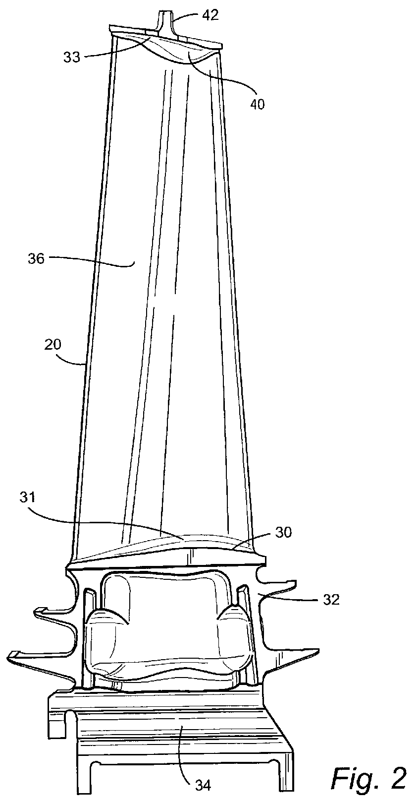
- Each bucket 20 of the second stage is provided with a platform 30, a shank 32 and a substantially or near axial entry dovetail 34 for connection with a complementary-shaped mating dovetail, not shown, on the rotor wheel 21. It will also be appreciated that each bucket 20 has a bucket airfoil 36, for example, as illustrated in Figure 2. Thus, each of the buckets 20 has a bucket airfoil profile at any cross-section from the airfoil root 31 to the bucket tip 33 in the shape of an airfoil.
- the bucket 20 includes a fillet 40 between the tip of the airfoil 36 and a tip shroud 42.
- the tip shroud 42 includes a seal 44 extending in a circumferential direction and having a cutter tooth 44 for sealing with a fixed shroud.
- the fillet 40 extends about the intersection between the tip of the airfoil and the tip shroud 42.
- the fillet 40 is sized and configured about the intersection of the tip shroud and airfoil tip to minimize creep, as well as the mass of the fillet, as a function of the location of the localized stresses about the intersection. That is, the shape of the fillet is biased toward the tip shroud or the airfoil in accordance with a stress analysis at each location about the intersection such that the high local stresses are accommodated and the mass of the fillet at each such location is minimized.
- the tip shroud fillet 40 is defined by fifteen points P1-P15 ( Figure 9) in an X, Y coordinate system about the intersection of the tip shroud and airfoil tip. At each X, Y location, the configuration of the fillet is determined by three parameters, offset 1 (O1), offset 2 (O2) and Rho. By defining the variable conical fillet 40 using these parameters, tip shroud creep life is optimized, while maintaining the mass of the bucket to a minimum.
- the origin 48 extends along the stacking axis of the airfoil in a radial direction.
- the X, Y coordinates and the origin use the same X, Y coordinates as set forth in co-pending application Serial No. 10/460,205, filed June 13, 2003 (Attorney Dkt. No. 839-1460); (GE Dkt. 134755), the contents of which are incorporated herein by reference.
- FIG 9 Also illustrated in Figure 9 are a plurality of locations about the intersection of the airfoil 36 and the undersurface of the tip shroud 42 and designated by the letter P, followed by a number defining the location, the intersection being designated an apex location in Figure 7 at 52.
- the locations P1-P15 are defined by the X, Y coordinates set forth in the table.
- Offset 1 as illustrated in Figure 7 and designated O1 is a distance in inches along a normal from the airfoil 36 at each X, Y location designated P and projected along the airfoil surface.
- Offset O2 defines in inches a distance along a normal from the tip shroud 42 at each X, Y location P and projected along the undersurface of the tip shroud.
- the offsets O1 and O2 are determined by finite stress analysis in an iterative process at each location about the tip shroud and airfoil tip intersection, resulting in a more even distribution of stresses about the fillet as well as minimization of the bucket mass at the fillet region.
- the offsets O1 and O2 intersect at 54 in Figure 7. Normal projections from the intersection 54 onto the tip shroud and airfoil define edge points 56 and 58, respectively, which, upon connection about the respective tip shroud and airfoil, define edges of the fillet.
- Rho is a non-dimensional shape parameter ratio at each location P. Rho is the ratio of D1 / D1 + D2 wherein, as illustrated in Figure 8, D1 is a distance between a midpoint 59 of a chord 60 extending between edge points 56 and 58 and a shoulder point 62 on the surface of fillet 40 and D2 is a distance between the shoulder point 62 and the apex location 52.
- D1 is a distance between a midpoint 59 of a chord 60 extending between edge points 56 and 58 and a shoulder point 62 on the surface of fillet 40
- D2 is a distance between the shoulder point 62 and the apex location 52.
- the surface shapes of the fillets i.e., the fillet profile section 64 at each location P, are joined smoothly to one another to form the nominal fillet profile about the intersection of the airfoil tip and the tip shroud.
- the shape of the fillet surface 64 may vary dependent on the value of Rho. For example, a small value of Rho produces a very flat conic surface, while a large Rho value produces a very pointed conic.
- Rho value thus determines the shape of the conic having a parabolic shape at Rho equals 0.5, an elliptical shape where Rho is greater than 0.0 and less than 0.5 and a hyperbolic shape where Rho is greater than 0.5 and less than 1.0.
- the values of A and B in Table I are the distances in inches of the edge points to the intersection of offsets O1 and O2.
- the Z value in Table I is the height of the airfoil and Z' is the distance between the axis of rotation and the airfoil tip.
- the location of the radial Z axis extending perpendicular to the X-Y plane, is determined relative to predetermined reference surfaces in the shank 34 of the bucket. With specific reference to Figures 3 and 4, the Z axis is located 1.866 inches from a forward edge 66 of the forward bucket tang 68 ( Figure 3), along the X axis, and 0.517 inches from the outside edge 70 of the seal pin 72 ( Figure 4), in a direction normal to the shank of the bucket.
- the distance between the outside edges of the respective pins 72, 73 is 1.153 inches (Figure 4).
- the diameters of pins 72 and 73 are 0.224 inches.
- the values determining the surface configuration of the fillet 40 given in Table I are for a nominal fillet.
- ⁇ typical manufacturing tolerances i.e., ⁇ values, including any coating thicknesses, are additive to the fillet surface configuration 64 as determined from the Table I.
- a distance of ⁇ 0.160 inches in a direction normal to any surface location along the fillet 40 defines a fillet profile envelope for this particular fillet 40, i.e., a range of variation between an ideal configuration of the fillet as given by the Table I above and a range of variations in the fillet configuration at nominal cold or room temperature.
- the fillet configuration is robust to this range of variation without impairment of mechanical and aerodynamic functions, while retaining the desired even distribution of stresses about the fillet region.
- Table I defines the fillet profile about the intersection of the airfoil tip and the tip shroud. Any number of X, Y locations may be used to define this profile.
- the profiles defined by the values of Table I embrace fillet profiles intermediate the given X, Y locations as well as profiles defined using fewer X, Y locations when the profiles defined by Table I are connected by smooth curves extending between the given locations of Table I.
- the fillet disclosed in the above table may be scaled up or scaled down geometrically for use in other similar fillet designs in other turbines.
- the offsets O1 and O2 as well as the X and Y coordinate values may be scaled upwardly or downwardly by multiplying or dividing those values by a constant number to produce a scaled-up or scaled-down version of the fillet 40.
- the Rho value would not be multiplied or divided by the constant number since it is a non-dimensional value.
- the fillet may be defined in relation to the airfoil since the Cartesian coordinate system used to define the fillet and to define the airfoil identified above are common.
- the fillet may be defined in relation to the airfoil shape of each second stage bucket airfoil 36 at 92% span just radially inwardly of the fillet.
- a Cartesian coordinate system of X, Y and Z values wherein the X, Y coordinate values are given in Table II below define the profile of the bucket airfoil at 92% span.
- the coordinate values for the X and Y coordinates are set forth in inches in Table II although other units of dimensions may be used when the values are appropriately converted.
- the Cartesian coordinate system has orthogonally-related X, Y and Z axes and the X axis lies parallel to the turbine rotor centerline, i.e., the rotary axis and a positive X coordinate value is axial toward the aft, i.e., exhaust end of the turbine.
- the positive Y coordinate value looking aft extends tangentially in the direction of rotation of the rotor and the positive Z coordinate value is radially outwardly toward the bucket tip.
- the profile section 39 at 92% span is fixed.
- the fillet surface configuration is defined in relation to the airfoil profile at 92% span.
- Other percentage spans could be used to define this relationship and the 92% span as used is exemplary only.
- a distance of ⁇ 0.160 inches in a direction normal to any surface location along the airfoil profile at 92% span defines an airfoil profile envelope, i.e., a range of variation between measured points on the actual airfoil surface at nominal cold or room temperature and the ideal position of those points as given in Table II below at the same temperature.
- the bucket airfoil at 92% span is robust to this range of variation without impairment of mechanical and aerodynamic functions.
Landscapes
- Engineering & Computer Science (AREA)
- Mechanical Engineering (AREA)
- General Engineering & Computer Science (AREA)
- Architecture (AREA)
- Turbine Rotor Nozzle Sealing (AREA)
Abstract
Description
- The present invention relates to a variable conical fillet between an airfoil tip of a turbine bucket and a bucket tip shroud and particularly relates to a conical fillet shaped and sized to improve part life, performance and manufacturing of the turbine bucket
- Turbine buckets generally comprise an airfoil, a platform, shank and dovetail along a radial inner end portion of the bucket and often a tip shroud at the tip of the airfoil in mechanical engagement with tip shrouds of adjacent buckets. The tip shroud and airfoil of a conventional turbine bucket are typically provided with a simple fillet shape of a predetermined size and generally of a constant radius about the intersection of the tip shroud and the airfoil tip. That is, a generally uniform radius was applied to the shroud fillet as the fillet was applied about the intersection of the airfoil tip and tip shroud. The fillet lowered the stress concentration between the airfoil and tip shroud.
- While the stresses were reduced by use of constant radius fillets, it was discovered that high stresses in the fillet region were localized at various locations or points in and about the fillet between the airfoil and tip shroud and that such localized stresses lead to significant decreases in bucket life. Thus, while stresses were reduced by the application of fillets of constant radius, the localized high stresses in critical areas were still present. These stresses reduced the creep life of the tip shroud which can lead to premature failure of the bucket. It will also be appreciated that the failure of a single bucket causes the turbine to be taken offline for repair. This is a time-consuming and costly outage, causing the customer as well as the turbine producer to incur higher costs due to unproductivity, labor, part repair, outage time and replacement. Consequently, there has developed a need for a customization of the fillet between the tip of the airfoil and the tip shroud of a bucket to provide a more uniform distribution of stress taking into account the high localized stresses about the fillet as well as reducing the mass of the fillet thereby to extend the creep life of the tip shroud.
- In accordance with the preferred embodiment of the present invention, there is provided a variable conical fillet between the airfoil tip and the tip shroud which minimizes creep as well as the mass of the fillet by varying the fillet size and configuration as a function of the high localized stresses about the intersection of the airfoil tip and tip shroud. The variable conical fillet profile is a function of an
offset 1, anoffset 2, Rho and discrete X, Y apex locations about the intersection of the airfoil and tip shroud.Offset 1 is a distance normal to the airfoil surface at each apex location projected along the airfoil surface andoffset 2 is a distance extending normal to the tip shroud undersurface at each apex location projected along the tip shroud undersurface. Normals projected onto the airfoil surface and tip shroud undersurface from the intersection ofoffsets - Particularly, the optimized conical tip shroud fillet hereof is defined, in a preferred embodiment, by 15 locations or points about the intersection of the tip shroud and airfoil tip with each location having three parameters, i.e.,
offset 1,offset 2 and Rho, which define the extent and shape of the fillet at that location. By varying the fillet in accordance with these parameters about the intersection, tip shroud creep life can be maximized while minimizing the mass of the bucket at the fillet. Particular locations and parameters are set forth in Table I below for the tip shroud/airfoil fillet of a second stage of a three stage turbine having 92 buckets. It will be appreciated that the number of locations at which these parameters are applied may vary while maintaining the shape of the fillet within a robust envelope sufficient to achieve the objectives of maximizing creep life and reducing bucket mass. - In a preferred embodiment according to the present invention, there is provided a turbine bucket having an airfoil, an airfoil tip, a tip shroud, and a fillet about an intersection of said airfoil tip and the tip shroud, the fillet having a fillet profile variable about the intersection as a function of localized stresses about the intersection.
- In a further preferred embodiment according to the present invention, there is provided a turbine bucket having an airfoil, an airfoil tip, a tip shroud and a fillet about an intersection of the airfoil tip and the tip shroud, the fillet having a nominal profile substantially in accordance with coordinate values of X and Y,
offset 1,offset 2 and Rho set forth in Table 1 wherein X and Y define in inches discrete apex locations about the intersection of the airfoil tip and tip shroud,offset 1 andoffset 2 are distances in inches perpendicular to the airfoil surface and tip shroud undersurface, respectively, at each respective X, Y location projected along the airfoil surface and tip shroud undersurface and which offsets intersect with one another such that normal projections from the intersection of the offsets onto the tip shroud undersurface and airfoil surface, respectively, define edge points which, upon connection about the respective tip shroud and airfoil, define edges of the fillet, and Rho is a non-dimensional shape parameter ratio of D1 / D1 + D2 at each apex location, wherein D1 is a distance between a midpoint along a chord between the fillet edge points and a shoulder point on a surface of the fillet and D2 is a distance between the shoulder point and the apex location, the fillet edge points on the tip shroud and the airfoil at each X, Y location being connected by a smooth continuing arc passing through the shoulder point in accordance with the shape parameter Rho to define a profile section at each apex location, the profile sections at each apex location being joined smoothly with one another to form the nominal fillet profile. - The invention will now be described in greater detail, by way of example, with reference to the drawings, in which:-
- FIGURE 1 is a schematic representation of a hot gas path through multiple stages of a gas turbine and illustrates a second stage bucket airfoil having a conical tip shroud fillet according to a preferred embodiment of the present invention;
- FIGURES 2 and 3 are opposite side elevational views of the second stage bucket of Figure 1 as viewed in a generally circumferential direction;
- FIGURE 4 is a partial enlarged front elevation of the bucket illustrated in Figure 3;
- FIGURE 5 is a cross-sectional view of the airfoil and tip shroud taken generally about on line 5-5 in Figure 3;
- FIGURE 6 is an enlarged side elevational view of the conical tip shroud fillet at the bucket tip;
- FIGURES 7 and 8 are cross-sectional views thereof taken through the airfoil and tip shroud generally about on line 7-7 in Figure 5; and
- FIGURE 9 is an end view of the tip shroud looking radially inwardly illustrating the locations of the X, Y and Z coordinates set forth in Table 1 below.
-
- Referring now to the drawings, particularly to Figure 1, there is illustrated a hot gas path, generally designated 10, of a
gas turbine 12 including a plurality of turbine stages. Three stages are illustrated. For example, the first stage comprises a plurality of circumferentially spacednozzles 14 andbuckets 16. The nozzles are circumferentially spaced one from the other and fixed about the axis of the rotor. Thefirst stage buckets 16, of course, are mounted on theturbine rotor 17 via arotor wheel 19. A second stage of theturbine 12 is also illustrated, including a plurality of circumferentially spacednozzles 18 and a plurality of circumferentially spacedbuckets 20 mounted on therotor 17 via arotor wheel 21. The third stage is also illustrated including a plurality of circumferentially spacednozzles 22 andbuckets 24 mounted onrotor 17 via arotor wheel 23. It will be appreciated that the nozzles and buckets lie in thehot gas path 10 of the turbine, the direction of flow of the hot gas through thehot gas path 10 being indicated by thearrow 26. - Each
bucket 20 of the second stage is provided with aplatform 30, ashank 32 and a substantially or nearaxial entry dovetail 34 for connection with a complementary-shaped mating dovetail, not shown, on therotor wheel 21. It will also be appreciated that eachbucket 20 has abucket airfoil 36, for example, as illustrated in Figure 2. Thus, each of thebuckets 20 has a bucket airfoil profile at any cross-section from theairfoil root 31 to thebucket tip 33 in the shape of an airfoil. - Referring now to Figures 2-6, the
bucket 20 includes afillet 40 between the tip of theairfoil 36 and atip shroud 42. As illustrated in Figures 2, 3 and 8, thetip shroud 42 includes aseal 44 extending in a circumferential direction and having acutter tooth 44 for sealing with a fixed shroud. Thefillet 40 extends about the intersection between the tip of the airfoil and thetip shroud 42. In accordance with the present invention, thefillet 40 is sized and configured about the intersection of the tip shroud and airfoil tip to minimize creep, as well as the mass of the fillet, as a function of the location of the localized stresses about the intersection. That is, the shape of the fillet is biased toward the tip shroud or the airfoil in accordance with a stress analysis at each location about the intersection such that the high local stresses are accommodated and the mass of the fillet at each such location is minimized. - In a preferred embodiment of the present invention, the
tip shroud fillet 40 is defined by fifteen points P1-P15 (Figure 9) in an X, Y coordinate system about the intersection of the tip shroud and airfoil tip. At each X, Y location, the configuration of the fillet is determined by three parameters, offset 1 (O1), offset 2 (O2) and Rho. By defining the variableconical fillet 40 using these parameters, tip shroud creep life is optimized, while maintaining the mass of the bucket to a minimum. - Particularly, and referring to Figure 9, there is illustrated an X, Y coordinate system with the X axis in Figure 9 extending horizontally at Y=0 and the Y axis extending vertically at X=0, the axes intersecting at an
origin 48. Theorigin 48 extends along the stacking axis of the airfoil in a radial direction. The X, Y coordinates and the origin use the same X, Y coordinates as set forth in co-pending application Serial No. 10/460,205, filed June 13, 2003 (Attorney Dkt. No. 839-1460); (GE Dkt. 134755), the contents of which are incorporated herein by reference. Also illustrated in Figure 9 are a plurality of locations about the intersection of theairfoil 36 and the undersurface of thetip shroud 42 and designated by the letter P, followed by a number defining the location, the intersection being designated an apex location in Figure 7 at 52. In Table I below, the locations P1-P15 are defined by the X, Y coordinates set forth in the table. - The configuration of the
conical fillet 40 is dependent at each X, Y location upon three parameters:offset 1,offset 2 and Rho.Offset 1 as illustrated in Figure 7 and designated O1 is a distance in inches along a normal from theairfoil 36 at each X, Y location designated P and projected along the airfoil surface. Offset O2 defines in inches a distance along a normal from thetip shroud 42 at each X, Y location P and projected along the undersurface of the tip shroud. The offsets O1 and O2 are determined by finite stress analysis in an iterative process at each location about the tip shroud and airfoil tip intersection, resulting in a more even distribution of stresses about the fillet as well as minimization of the bucket mass at the fillet region. The offsets O1 and O2 intersect at 54 in Figure 7. Normal projections from theintersection 54 onto the tip shroud and airfoil defineedge points - Rho is a non-dimensional shape parameter ratio at each location P. Rho is the ratio of D1 / D1 + D2 wherein, as illustrated in Figure 8, D1 is a distance between a
midpoint 59 of achord 60 extending betweenedge points shoulder point 62 on the surface offillet 40 and D2 is a distance between theshoulder point 62 and theapex location 52. Thus, by connecting the edge points 56 and 58 determined byoffsets shoulder point 62 in accordance with the shape parameter Rho, there is defined a fillet profile section at each apex location P which minimizes the stress. It will be appreciated that the surface shapes of the fillets, i.e., thefillet profile section 64 at each location P, are joined smoothly to one another to form the nominal fillet profile about the intersection of the airfoil tip and the tip shroud. It will be appreciated from a review of Figure 8 that the shape of thefillet surface 64 may vary dependent on the value of Rho. For example, a small value of Rho produces a very flat conic surface, while a large Rho value produces a very pointed conic. The Rho value thus determines the shape of the conic having a parabolic shape at Rho equals 0.5, an elliptical shape where Rho is greater than 0.0 and less than 0.5 and a hyperbolic shape where Rho is greater than 0.5 and less than 1.0. - The X, Y coordinate values, as well as the parameters offset 1 (O1), offset 2 (O2), D1, D2 and Rho are given in Table I as follows:
Point X Y Z Z' Centerline Offset 1 From the Airfloil Offset 2 from the tip Shroud A B D1 D2 Rho P1 -0.793 1.272 10.669 34.769 0.070 0.070 0.085 0.083 0.031 0.031 0.50 P2 -0.548 1.101 10.725 34.825 0.150 0.100 0.191 0.133 0.063 0.063 0.50 P3 -0.349 0.907 10.769 34.869 0.200 0.175 0.238 0.220 0.088 0.088 0.50 P4 -0.089 0.527 10.831 34.931 0.310 0.325 0.368 0.371 0.113 0.169 0.40 P5 0.135 0.157 10.882 34.982 0.575 0.375 0.640 0.465 0.170 0.255 0.40 P6 0.334 -0.178 10.924 35.024 0.475 0.340 0.522 0.411 0.160 0.195 0.45 P7 0.459 -0.387 10.949 35.049 0.325 0.285 0.357 0.331 0.130 0.130 0.50 P8 0.546 -0.522 10.965 35.065 0.225 0.230 0.243 0.250 0.095 0.095 0.50 P9 0.717 -0.721 10.998 35.098 0.070 0.070 0.068 0.066 0.025 0.025 0.50 P10 -0.595 1.346 10.705 34.805 0.400 0.275 0.370 0.225 0.090 0.110 0.45 P11 -0.312 1.179 10.769 34.869 0.600 0.450 0.527 0.349 0.115 0.170 0.40 P12 -0.074 0.875 10.828 34.928 0.500 0.400 0.448 0.330 0.103 0.155 0.40 P13 0.140 0.541 10.880 34.980 0.250 0.300 0.213 0.267 0.070 0.085 0.45 P14 0.345 0.164 10.927 35.027 0.150 0.175 0.122 0.157 0.045 0.045 0.50 P15 0.646 -0.466 10.990 35.090 0.100 0.100 0.085 0.091 0.028 0.028 0.50 - The values of A and B in Table I are the distances in inches of the edge points to the intersection of offsets O1 and O2. The Z value in Table I is the height of the airfoil and Z' is the distance between the axis of rotation and the airfoil tip. The location of the radial Z axis extending perpendicular to the X-Y plane, is determined relative to predetermined reference surfaces in the
shank 34 of the bucket. With specific reference to Figures 3 and 4, the Z axis is located 1.866 inches from aforward edge 66 of the forward bucket tang 68 (Figure 3), along the X axis, and 0.517 inches from theoutside edge 70 of the seal pin 72 (Figure 4), in a direction normal to the shank of the bucket. Note that the distance between the outside edges of therespective pins pins - It will also be appreciated that the values determining the surface configuration of the
fillet 40 given in Table I are for a nominal fillet. Thus, ± typical manufacturing tolerances, i.e., ± values, including any coating thicknesses, are additive to thefillet surface configuration 64 as determined from the Table I. Accordingly, a distance of ±0.160 inches in a direction normal to any surface location along thefillet 40 defines a fillet profile envelope for thisparticular fillet 40, i.e., a range of variation between an ideal configuration of the fillet as given by the Table I above and a range of variations in the fillet configuration at nominal cold or room temperature. The fillet configuration is robust to this range of variation without impairment of mechanical and aerodynamic functions, while retaining the desired even distribution of stresses about the fillet region. - Further, Table I defines the fillet profile about the intersection of the airfoil tip and the tip shroud. Any number of X, Y locations may be used to define this profile. Thus, the profiles defined by the values of Table I embrace fillet profiles intermediate the given X, Y locations as well as profiles defined using fewer X, Y locations when the profiles defined by Table I are connected by smooth curves extending between the given locations of Table I.
- Also, it will be appreciated that the fillet disclosed in the above table may be scaled up or scaled down geometrically for use in other similar fillet designs in other turbines. For example, the offsets O1 and O2, as well as the X and Y coordinate values may be scaled upwardly or downwardly by multiplying or dividing those values by a constant number to produce a scaled-up or scaled-down version of the
fillet 40. The Rho value would not be multiplied or divided by the constant number since it is a non-dimensional value. - It will also be appreciated that the fillet may be defined in relation to the airfoil since the Cartesian coordinate system used to define the fillet and to define the airfoil identified above are common. Thus, the fillet may be defined in relation to the airfoil shape of each second
stage bucket airfoil 36 at 92% span just radially inwardly of the fillet. A Cartesian coordinate system of X, Y and Z values wherein the X, Y coordinate values are given in Table II below define the profile of the bucket airfoil at 92% span. The Z coordinate value at 92% span is preferably 10.410 inches, the Z=0 value being preferably at 24.1 inches along the radial Z axis from the rotor centerline. The coordinate values for the X and Y coordinates are set forth in inches in Table II although other units of dimensions may be used when the values are appropriately converted. The Cartesian coordinate system has orthogonally-related X, Y and Z axes and the X axis lies parallel to the turbine rotor centerline, i.e., the rotary axis and a positive X coordinate value is axial toward the aft, i.e., exhaust end of the turbine. The positive Y coordinate value looking aft extends tangentially in the direction of rotation of the rotor and the positive Z coordinate value is radially outwardly toward the bucket tip. - By connecting the X and Y values with smooth continuing arcs, the
profile section 39 at 92% span is fixed. By using a common Z-axis origin for the X, Y coordinate systems for the fillet points and the points defining the airfoil profile at 92% span, the fillet surface configuration is defined in relation to the airfoil profile at 92% span. Other percentage spans could be used to define this relationship and the 92% span as used is exemplary only. These values represent the fillet and the airfoil profile at 92% span are at ambient, non-operating or non-hot conditions and are for an uncoated surface. - Like
fillet 40, there are typical manufacturing tolerances as well as coatings which must be accounted for in the actual profile of the airfoil. Accordingly, the values for the profile at 92% span given in Table II are for a nominal airfoil. It will therefore be appreciated that ± typical manufacturing tolerances, i.e., ± values, including any coating thicknesses, are additive to the X and Y values given in Table II below. Accordingly, a distance of ± 0.160 inches in a direction normal to any surface location along the airfoil profile at 92% span defines an airfoil profile envelope, i.e., a range of variation between measured points on the actual airfoil surface at nominal cold or room temperature and the ideal position of those points as given in Table II below at the same temperature. The bucket airfoil at 92% span is robust to this range of variation without impairment of mechanical and aerodynamic functions.X Y Z' X Y Z' X Y Z' -0.815 1.203 10.41 0.308 -0.119 10.410 0.367 0.129 10.410 -0.812 1.158 10.41 0.331 -0.157 10.410 0.346 0.168 10.410 -0.783 1.126 10.41 0.354 -0.196 10.410 0.325 0.208 10.410 -0.740 1.112 10.41 0.377 -0.234 10.410 0.304 0.247 10.410 -0.697 1.100 10.41 0.400 -0.273 10.410 0.282 0.287 10.410 -0.655 1.086 10.41 0424 -0.311 10.410 0.260 0.326 10.410 -0.613 1.070 10.41 0.447 -0.349 10.410 0.239 0.365 10.410 -0.573 1.050 10.41 0.470 -0.387 10.410 0.216 0.404 10.410 -0.534 1.028 10.41 0.494 -0.425 10.410 0.194 0.442 10.410 -0.497 1.003 10.41 0.517 -0.463 10.410 0.171 0.481 10.410 -0.462 0.975 10.41 0.541 -0.501 10.410 0.148 0.519 10,410 -0.428 0.946 10.41 0.565 -0.539 10.410 0.125 0.558 10.410 -0.396 0.915 10.41 0.589 -0.577 10.410 0.101 0.596 10,410 - 0.365 0.883 10.41 0.613 -0.614 10.410 0.077 0.633 10,410 -0.335 0.849 10.41 0.637 -0.652 10.410 0.053 0.671 10.410 -0.305 0.815 10.41 0.661 -0.690 10.410 0.028 0.708 10.410 -0.277 0.781 10.41 0.685 -0.728 10.410 0.003 0.745 10.410 -0.249 0.746 10.41 0.715 -0.761 10.410 -0.022 0.782 10.410 -0.222 0.710 10.41 0.757 -0.757 10.410 -0.048 0.819 10.410 -0.195 0.674 10.41 0.774 -0.718 10.410 -0.075 0.855 10.410 -0.169 0.638 10.41 0.758 -0.676 10.410 -0.102 0.891 10.410 -0.143 0.602 10.41 0.739 -0.636 10.410 -0.129 0.926 10.410 -0.118 0.565 10.41 0.720 -0.595 10.410 -0.157 0.961 10.410 -0.093 0.528 10.41 0.701 -0.554 10.410 -0.186 0.995 10.410 -0.068 0.490 10.41 0.683 -0.514 10.410 -0.216 1.028 10.410 -0.044 0.453 10.41 0.664 -0.473 10.410 -0.247 1.061 10.410 -0.019 0.415 10.41 0.645 -0.433 10.410 -0.278 1.092 10.410 0.005 0.377 10.41 0.626 -0.392 10.410 -0.311 1.123 10.410 0.029 0.340 10.41 0.607 -0.352 10.410 -0.345 1.152 10.410 0.052 0.302 10.41 0.587 -0.311 10.410 -0.380 1.179 10.410 0.076 0.264 10.41 0.568 -0.271 10.410 -0.417 1.204 10.410 0.099 0.226 10.41 0.548 -0.231 10.410 -0.456 1.227 10.410 0.123 0.187 10.41 0.529 -0.191 10.410 -0.496 1.247 10.410 0.146 0.149 10.41 0.509 -0.151 10.410 -0.538 1.263 10.410 0.169 0.111 10.41 0.489 -0.110 10.410 -0.581 1.276 10.410 0.193 0.073 10.41 0.469 -0.070 10.410 -0.625 1.284 10.410 0.216 0.034 10.41 0.449 -0.030 10.410 -0.669 1.286 10.410 0.239 -0.004 10.41 0.428 0.010 10.410 -0.714 1.281 10.410 0.262 -0.042 10.41 0.408 0.049 10.410 -0.756 1.266 10.410 0.285 -0.081 10.41 0.387 0.089 10.410 -0.792 1.240 10.410 - Thus, by defining the airfoil profile at 92% span, the same Cartesian coordinate system as used to define the
fillet 40, the relationship between the fillet and airfoil is established. - For the sake of good order, various aspects of the invention are set out in the following clauses:-
- 1. A turbine bucket having an airfoil, an airfoil tip, a tip shroud, and a fillet about an intersection of said airfoil tip and said tip shroud, said fillet having a fillet profile variable about said intersection as a function of localized stresses about said intersection.
- 2. A turbine bucket according to
Clause 1 wherein the fillet profile at one point of intersection is one of a parabola, an ellipse and a hyperbola. - 3. A turbine bucket according to
Clause 2 wherein the fillet profile at another point of intersection is a curve different from said one parabola, an ellipse and hyperbola at said one point of intersection. - 4. A turbine bucket having an airfoil, an airfoil tip, a tip shroud and a fillet about an intersection of said airfoil tip and said tip shroud, said fillet having a nominal profile substantially in accordance with coordinate values of X and Y, offset 1, offset 2 and Rho set forth in Table 1 wherein X and Y define in inches discrete apex locations about the intersection of the airfoil tip and tip shroud, offset 1 and offset 2 are distances in inches perpendicular to the airfoil surface and tip shroud undersurface, respectively, at each respective X, Y location projected along the airfoil surface and tip shroud undersurface and which offsets intersect with one another such that normal projections from the intersection of said offsets onto the tip shroud undersurface and airfoil surface, respectively, define edge points which, upon connection about the respective tip shroud and airfoil, define edges of the fillet, and Rho is a non-dimensional shape parameter ratio of D1 / D1 + D2 at each apex location, wherein D1 is a distance between a midpoint along a chord between said fillet edge points and a shoulder point on a surface of said fillet and D2 is a distance between the shoulder point and the apex location, said fillet edge points on said tip shroud and said airfoil at each X, Y location being connected by a smooth continuing arc passing through the shoulder point in accordance with the shape parameter Rho to define a profile section at each apex location, the profile sections at each apex location being joined smoothly with one another to form the nominal fillet profile.
- 5. A turbine bucket according to Clause 4 wherein said fillet includes linear distances of A and B in inches set forth in Table I from each corresponding apex location to said edge points along the tip shroud and airfoil, respectively.
- 6. A bucket according to Clause 4 forming part of a second stage of a turbine.
- 7. A bucket according to Clause 4 wherein said fillet profile lies in an envelope within +/- 0.160 inches in a direction normal to any fillet surface location.
- 8. A bucket according to Clause 4 wherein the X and Y distances and the
offsets - 9. A turbine bucket according to Clause 4 wherein said fillet includes linear distances of A and B in inches set forth in Table I from each corresponding apex location to said edge points along the tip shroud and airfoil, respectively, said fillet profile lying in an envelope within +/- 0.160 inches in a direction normal to any fillet surface location.
- 10. A turbine bucket according to Clause 4 wherein said X and Y values form a Cartesian coordinate system having a Z axis, said bucket airfoil having an airfoil shape, the airfoil having a nominal profile substantially in accordance with Cartesian coordinate values of X, Y and Z are set forth in Table II wherein the Z value is at 92% span of the airfoil and wherein X and Y values in Table II are distances in inches which, when connected by smooth continuing arcs, define an airfoil profile section at 92% span, the X, Y and Z Cartesian coordinate systems for the fillet and airfoil profile being coincident.
- 11. A turbine bucket according to
Clause 10 forming part of a second stage of a turbine. - 12. A turbine bucket according to
Clause 10 wherein said airfoil shape lies in an envelope within ±0.160 inches in a direction normal to any airfoil surface location. -
Claims (10)
- A turbine bucket (20) having an airfoil (36), an airfoil tip (33), a tip shroud (42), and a fillet (40) about an intersection of said airfoil tip and said tip shroud, said fillet having a fillet profile variable about said intersection as a function of localized stresses about said intersection.
- A turbine bucket according to Claim 1 wherein the fillet profile at one point of intersection is one of a parabola, an ellipse and a hyperbola.
- A turbine bucket according to Claim 2 wherein the fillet profile at another point of intersection is a curve different from said one parabola, an ellipse and hyperbola at said one point of intersection.
- A turbine bucket (20) having an airfoil (36), an airfoil tip (33), a tip shroud (42) and a fillet (40) about an intersection of said airfoil tip and said tip shroud, said fillet having a nominal profile substantially in accordance with coordinate values of X and Y, offset 1, offset 2 and Rho set forth in Table 1 wherein X and Y define in inches discrete apex locations about the intersection of the airfoil tip and tip shroud, offset 1 and offset 2 are distances in inches perpendicular to the airfoil surface and tip shroud undersurface, respectively, at each respective X, Y location projected along the airfoil surface and tip shroud undersurface and which offsets intersect (54) with one another such that normal projections from the intersection of said offsets onto the tip shroud undersurface and airfoil surface, respectively, define edge points (56, 58) which, upon connection about the respective tip shroud and airfoil, define edges of the fillet, and Rho is a non-dimensional shape parameter ratio of D1 / D1 + D2 at each apex location (52), wherein D1 is a distance between a midpoint (59) along a chord (60) between said fillet edge points (56, 58) and a shoulder point (60) on a surface of said fillet and D2 is a distance between the shoulder point and the apex location, said fillet edge points on said tip shroud and said airfoil at each X, Y location being connected by a smooth continuing arc passing through the shoulder point in accordance with the shape parameter Rho to define a profile section at each apex location, the profile sections at each apex location being joined smoothly with one another to form the nominal fillet profile.
- A turbine bucket according to Claim 4 wherein said fillet (40) includes linear distances of A and B in inches set forth in Table I from each corresponding apex location (52) to said edge points (56, 58) along the tip shroud and airfoil, respectively.
- A bucket according to Claim 4 forming part of a second stage of a turbine.
- A bucket according to Claim 4 wherein said fillet profile lies in an envelope within +/- 0.160 inches in a direction normal to any fillet surface location.
- A bucket according to Claim 4 wherein the X and Y distances and the offsets 1 and 2 are scalable as a function of the same constant or number to provide a scaled up or scaled down fillet profile.
- A turbine bucket according to Claim 4 wherein said fillet includes linear distances of A and B in inches set forth in Table I from each corresponding apex location to said edge points along the tip shroud and airfoil, respectively, said fillet profile lying in an envelope within +/- 0.160 inches in a direction normal to any fillet surface location.
- A turbine bucket according to Claim 4 wherein said X and Y values form a Cartesian coordinate system having a Z axis, said bucket airfoil having an airfoil shape, the airfoil having a nominal profile substantially in accordance with Cartesian coordinate values of X, Y and Z are set forth in Table II wherein the Z value is at 92% span of the airfoil and wherein X and Y values in Table II are distances in inches which, when connected by smooth continuing arcs, define an airfoil profile section (39) at 92% span, the X, Y and Z Cartesian coordinate systems for the fillet and airfoil profile being coincident.
Applications Claiming Priority (2)
| Application Number | Priority Date | Filing Date | Title |
|---|---|---|---|
| US639473 | 2003-08-13 | ||
| US10/639,473 US6857853B1 (en) | 2003-08-13 | 2003-08-13 | Conical tip shroud fillet for a turbine bucket |
Publications (3)
| Publication Number | Publication Date |
|---|---|
| EP1507064A2 true EP1507064A2 (en) | 2005-02-16 |
| EP1507064A3 EP1507064A3 (en) | 2008-12-31 |
| EP1507064B1 EP1507064B1 (en) | 2016-05-04 |
Family
ID=33565237
Family Applications (1)
| Application Number | Title | Priority Date | Filing Date |
|---|---|---|---|
| EP04254593.9A Expired - Lifetime EP1507064B1 (en) | 2003-08-13 | 2004-07-30 | Shaped tip shroud fillet for a turbine bucket |
Country Status (4)
| Country | Link |
|---|---|
| US (1) | US6857853B1 (en) |
| EP (1) | EP1507064B1 (en) |
| JP (1) | JP2005061414A (en) |
| CN (1) | CN100406680C (en) |
Cited By (10)
| Publication number | Priority date | Publication date | Assignee | Title |
|---|---|---|---|---|
| EP1731712A1 (en) * | 2005-06-06 | 2006-12-13 | General Electric Company | Tubine airfoil with variable and compound fillet |
| EP1559869A3 (en) * | 2004-01-31 | 2008-12-31 | United Technologies Corporation | Rotor blade for a turbomachine |
| EP1559871A3 (en) * | 2004-01-31 | 2009-01-07 | United Technologies Corporation | Rotor blade for a turbomachine |
| EP2372093A1 (en) * | 2010-03-31 | 2011-10-05 | Alstom Technology Ltd | Seal design on a shroud of a turbine blade |
| EP2738352A1 (en) * | 2012-11-30 | 2014-06-04 | General Electric Company | Fillet for use with a turbine rotor blade tip shroud |
| WO2017018981A1 (en) * | 2015-07-24 | 2017-02-02 | Siemens Aktiengesellschaft | Turbine blade with contoured tip shroud |
| EP3315720A3 (en) * | 2016-10-25 | 2018-06-06 | Rolls-Royce Deutschland Ltd & Co KG | Compressor rotor of a fluid flow machine |
| US10400610B2 (en) | 2017-02-14 | 2019-09-03 | General Electric Company | Turbine blade having a tip shroud notch |
| EP3623576A1 (en) * | 2018-09-17 | 2020-03-18 | MTU Aero Engines GmbH | Gas turbine rotor blade |
| US11125088B2 (en) | 2015-12-03 | 2021-09-21 | MTU Aero Engines AG | Stacking of rotor blades on centroids |
Families Citing this family (52)
| Publication number | Priority date | Publication date | Assignee | Title |
|---|---|---|---|---|
| JP4254352B2 (en) * | 2003-06-04 | 2009-04-15 | 株式会社Ihi | Turbine blade |
| JP2005214205A (en) * | 2004-01-31 | 2005-08-11 | United Technol Corp <Utc> | Rotor blade for rotary machine |
| US7134838B2 (en) * | 2004-01-31 | 2006-11-14 | United Technologies Corporation | Rotor blade for a rotary machine |
| US7094032B2 (en) * | 2004-02-26 | 2006-08-22 | Richard Seleski | Turbine blade shroud cutter tip |
| ITMI20060340A1 (en) * | 2006-02-27 | 2007-08-28 | Nuovo Pignone Spa | SHOVEL OF A ROTOR OF A SECOND STAGE OF A COMPRESSOR |
| ITMI20060341A1 (en) * | 2006-02-27 | 2007-08-28 | Nuovo Pignone Spa | SHOVEL OF A ROTOR OF A NON-STAGE OF A COMPRESSOR |
| US7887295B2 (en) * | 2007-11-08 | 2011-02-15 | General Electric Company | Z-Notch shape for a turbine blade |
| US7976280B2 (en) * | 2007-11-28 | 2011-07-12 | General Electric Company | Turbine bucket shroud internal core profile |
| US8057186B2 (en) * | 2008-04-22 | 2011-11-15 | General Electric Company | Shape for a turbine bucket tip shroud |
| JP5308077B2 (en) * | 2008-06-10 | 2013-10-09 | 三菱重工業株式会社 | Turbine and turbine blade |
| US8206095B2 (en) * | 2008-11-19 | 2012-06-26 | Alstom Technology Ltd | Compound variable elliptical airfoil fillet |
| US20110097205A1 (en) * | 2009-10-28 | 2011-04-28 | General Electric Company | Turbine airfoil-sidewall integration |
| WO2011070636A1 (en) * | 2009-12-07 | 2011-06-16 | 三菱重工業株式会社 | Turbine and turbine rotor blade |
| KR101305575B1 (en) | 2010-01-20 | 2013-09-09 | 미츠비시 쥬고교 가부시키가이샤 | Turbine rotor blade and turbo machine |
| US8641381B2 (en) * | 2010-04-14 | 2014-02-04 | General Electric Company | System and method for reducing grain boundaries in shrouded airfoils |
| GB2486488A (en) | 2010-12-17 | 2012-06-20 | Ge Aviat Systems Ltd | Testing a transient voltage protection device |
| WO2012095851A2 (en) | 2011-01-13 | 2012-07-19 | Cadent Ltd. | Methods, systems and accessories useful for procedures relating to dental implants |
| US8905715B2 (en) | 2011-03-17 | 2014-12-09 | General Electric Company | Damper and seal pin arrangement for a turbine blade |
| US8807928B2 (en) | 2011-10-04 | 2014-08-19 | General Electric Company | Tip shroud assembly with contoured seal rail fillet |
| US20130104397A1 (en) * | 2011-10-28 | 2013-05-02 | General Electric Company | Methods for repairing turbine blade tips |
| US9039382B2 (en) * | 2011-11-29 | 2015-05-26 | General Electric Company | Blade skirt |
| US9267386B2 (en) | 2012-06-29 | 2016-02-23 | United Technologies Corporation | Fairing assembly |
| US10344601B2 (en) | 2012-08-17 | 2019-07-09 | United Technologies Corporation | Contoured flowpath surface |
| US9932834B2 (en) | 2013-03-13 | 2018-04-03 | United Technologies Corporation | Rotor blade with a conic spline fillet at an intersection between a platform and a neck |
| EP2971565B1 (en) * | 2013-03-15 | 2024-09-04 | RTX Corporation | Airfoil with thickened root and fan and engine incorporating same |
| JP6604939B2 (en) | 2013-03-15 | 2019-11-13 | ユナイテッド テクノロジーズ コーポレイション | Control system, control method and gas turbine engine |
| US9828858B2 (en) | 2013-05-21 | 2017-11-28 | Siemens Energy, Inc. | Turbine blade airfoil and tip shroud |
| WO2014189875A1 (en) * | 2013-05-21 | 2014-11-27 | Siemens Energy, Inc. | Turbine blade tip shroud |
| US10233758B2 (en) | 2013-10-08 | 2019-03-19 | United Technologies Corporation | Detuning trailing edge compound lean contour |
| FR3014941B1 (en) * | 2013-12-18 | 2016-01-08 | Snecma | AUB FOR TURBOMACHINE WHEEL WHEEL AND METHOD OF MODELING THE SAME |
| US9879550B2 (en) | 2014-07-31 | 2018-01-30 | Pratt & Whitney Canada Corp. | Outer shroud with gusset |
| EP2987956A1 (en) * | 2014-08-18 | 2016-02-24 | Siemens Aktiengesellschaft | Compressor aerofoil |
| EP3034798B1 (en) * | 2014-12-18 | 2018-03-07 | Ansaldo Energia Switzerland AG | Gas turbine vane |
| US9920633B2 (en) | 2015-03-02 | 2018-03-20 | United Technologies Corporation | Compound fillet for a gas turbine airfoil |
| US10301945B2 (en) * | 2015-12-18 | 2019-05-28 | General Electric Company | Interior cooling configurations in turbine rotor blades |
| US10190421B2 (en) * | 2016-02-09 | 2019-01-29 | General Electric Company | Turbine bucket having tip shroud fillet, tip shroud cross-drilled apertures and profile |
| US10190417B2 (en) | 2016-02-09 | 2019-01-29 | General Electric Company | Turbine bucket having non-axisymmetric endwall contour and profile |
| US10001014B2 (en) | 2016-02-09 | 2018-06-19 | General Electric Company | Turbine bucket profile |
| US10161255B2 (en) | 2016-02-09 | 2018-12-25 | General Electric Company | Turbine nozzle having non-axisymmetric endwall contour (EWC) |
| US10196908B2 (en) | 2016-02-09 | 2019-02-05 | General Electric Company | Turbine bucket having part-span connector and profile |
| US10221710B2 (en) | 2016-02-09 | 2019-03-05 | General Electric Company | Turbine nozzle having non-axisymmetric endwall contour (EWC) and profile |
| US10125623B2 (en) | 2016-02-09 | 2018-11-13 | General Electric Company | Turbine nozzle profile |
| US10156149B2 (en) | 2016-02-09 | 2018-12-18 | General Electric Company | Turbine nozzle having fillet, pinbank, throat region and profile |
| US10526899B2 (en) * | 2017-02-14 | 2020-01-07 | General Electric Company | Turbine blade having a tip shroud |
| JP6982482B2 (en) * | 2017-12-11 | 2021-12-17 | 三菱パワー株式会社 | Variable vane and compressor |
| US10704392B2 (en) * | 2018-03-23 | 2020-07-07 | General Electric Company | Tip shroud fillets for turbine rotor blades |
| JP2021110291A (en) * | 2020-01-10 | 2021-08-02 | 三菱重工業株式会社 | Rotor blade and axial flow rotary machine |
| CN112282864A (en) * | 2020-11-16 | 2021-01-29 | 兰州长城机械工程有限公司 | Root protection technology for long-handled moving blades of flue gas turbine rotors |
| US11578607B2 (en) | 2020-12-15 | 2023-02-14 | Pratt & Whitney Canada Corp. | Airfoil having a spline fillet |
| US11236628B1 (en) * | 2020-12-16 | 2022-02-01 | General Electric Company | Turbine nozzle airfoil profile |
| US11459892B1 (en) * | 2021-04-30 | 2022-10-04 | General Electric Company | Compressor stator vane airfoils |
| US12546223B2 (en) | 2023-12-14 | 2026-02-10 | Pratt & Whitney Canada Corp. | Variable rim width turbine blade attachment |
Citations (2)
| Publication number | Priority date | Publication date | Assignee | Title |
|---|---|---|---|---|
| US5154581A (en) | 1990-05-11 | 1992-10-13 | Mtu Motoren- Und Turbinen- Union Munchen Gmbh | Shroud band for a rotor wheel having integral rotor blades |
| JPH07233703A (en) | 1994-02-23 | 1995-09-05 | Mitsubishi Heavy Ind Ltd | Shroud for gas turbine moving blade |
Family Cites Families (9)
| Publication number | Priority date | Publication date | Assignee | Title |
|---|---|---|---|---|
| GB1605335A (en) * | 1975-08-23 | 1991-12-18 | Rolls Royce | A rotor blade for a gas turbine engine |
| US4156582A (en) * | 1976-12-13 | 1979-05-29 | General Electric Company | Liquid cooled gas turbine buckets |
| US4259037A (en) * | 1976-12-13 | 1981-03-31 | General Electric Company | Liquid cooled gas turbine buckets |
| JPS61149504A (en) * | 1984-12-21 | 1986-07-08 | Nissan Motor Co Ltd | Turbine rotor structure in pneumatic machine |
| GB2251897B (en) * | 1991-01-15 | 1994-11-30 | Rolls Royce Plc | A rotor |
| US5397215A (en) * | 1993-06-14 | 1995-03-14 | United Technologies Corporation | Flow directing assembly for the compression section of a rotary machine |
| DE19650656C1 (en) * | 1996-12-06 | 1998-06-10 | Mtu Muenchen Gmbh | Turbo machine with transonic compressor stage |
| GB9823840D0 (en) * | 1998-10-30 | 1998-12-23 | Rolls Royce Plc | Bladed ducting for turbomachinery |
| US6524070B1 (en) * | 2000-08-21 | 2003-02-25 | General Electric Company | Method and apparatus for reducing rotor assembly circumferential rim stress |
-
2003
- 2003-08-13 US US10/639,473 patent/US6857853B1/en not_active Expired - Lifetime
-
2004
- 2004-07-30 EP EP04254593.9A patent/EP1507064B1/en not_active Expired - Lifetime
- 2004-08-12 JP JP2004234995A patent/JP2005061414A/en active Pending
- 2004-08-13 CN CNB2004100566720A patent/CN100406680C/en not_active Expired - Fee Related
Patent Citations (2)
| Publication number | Priority date | Publication date | Assignee | Title |
|---|---|---|---|---|
| US5154581A (en) | 1990-05-11 | 1992-10-13 | Mtu Motoren- Und Turbinen- Union Munchen Gmbh | Shroud band for a rotor wheel having integral rotor blades |
| JPH07233703A (en) | 1994-02-23 | 1995-09-05 | Mitsubishi Heavy Ind Ltd | Shroud for gas turbine moving blade |
Cited By (18)
| Publication number | Priority date | Publication date | Assignee | Title |
|---|---|---|---|---|
| EP1559869A3 (en) * | 2004-01-31 | 2008-12-31 | United Technologies Corporation | Rotor blade for a turbomachine |
| EP1559871A3 (en) * | 2004-01-31 | 2009-01-07 | United Technologies Corporation | Rotor blade for a turbomachine |
| EP1731712A1 (en) * | 2005-06-06 | 2006-12-13 | General Electric Company | Tubine airfoil with variable and compound fillet |
| US7371046B2 (en) | 2005-06-06 | 2008-05-13 | General Electric Company | Turbine airfoil with variable and compound fillet |
| US9441489B2 (en) | 2010-03-31 | 2016-09-13 | General Electric Technology Gmbh | Sealing structure on a shroud of a turbine blade |
| EP2372093A1 (en) * | 2010-03-31 | 2011-10-05 | Alstom Technology Ltd | Seal design on a shroud of a turbine blade |
| CH702980A1 (en) * | 2010-03-31 | 2011-10-14 | Alstom Technology Ltd | A seal structure of a shroud of a turbine blade. |
| EP2738352A1 (en) * | 2012-11-30 | 2014-06-04 | General Electric Company | Fillet for use with a turbine rotor blade tip shroud |
| US9322282B2 (en) | 2012-11-30 | 2016-04-26 | General Electric Company | Fillet for use with a turbine rotor blade tip shroud |
| WO2017018981A1 (en) * | 2015-07-24 | 2017-02-02 | Siemens Aktiengesellschaft | Turbine blade with contoured tip shroud |
| CN107849926A (en) * | 2015-07-24 | 2018-03-27 | 西门子公司 | Turbine moving blade with profile tip shroud |
| US11125088B2 (en) | 2015-12-03 | 2021-09-21 | MTU Aero Engines AG | Stacking of rotor blades on centroids |
| EP3181813B1 (en) * | 2015-12-03 | 2022-01-05 | MTU Aero Engines AG | Center-of-gravity threading of rotor blades |
| EP3315720A3 (en) * | 2016-10-25 | 2018-06-06 | Rolls-Royce Deutschland Ltd & Co KG | Compressor rotor of a fluid flow machine |
| US10995768B2 (en) | 2016-10-25 | 2021-05-04 | Rolls-Royce Deutschland Ltd & Co Kg | Compressor rotor of a fluid flow machine |
| US10400610B2 (en) | 2017-02-14 | 2019-09-03 | General Electric Company | Turbine blade having a tip shroud notch |
| EP3623576A1 (en) * | 2018-09-17 | 2020-03-18 | MTU Aero Engines GmbH | Gas turbine rotor blade |
| US11377966B2 (en) | 2018-09-17 | 2022-07-05 | MTU Aero Engines AG | Gas turbine moving blade |
Also Published As
| Publication number | Publication date |
|---|---|
| US6857853B1 (en) | 2005-02-22 |
| EP1507064A3 (en) | 2008-12-31 |
| JP2005061414A (en) | 2005-03-10 |
| CN1580496A (en) | 2005-02-16 |
| EP1507064B1 (en) | 2016-05-04 |
| US20050036890A1 (en) | 2005-02-17 |
| CN100406680C (en) | 2008-07-30 |
Similar Documents
| Publication | Publication Date | Title |
|---|---|---|
| EP1507064A2 (en) | Shaped tip shroud fillet for a turbine bucket | |
| US7063509B2 (en) | Conical tip shroud fillet for a turbine bucket | |
| US7396211B2 (en) | Stator blade airfoil profile for a compressor | |
| US6851931B1 (en) | Turbine bucket tip shroud edge profile | |
| US6685434B1 (en) | Second stage turbine bucket airfoil | |
| US6450770B1 (en) | Second-stage turbine bucket airfoil | |
| EP1498578A1 (en) | Turbine bucket tip shroud edge profile | |
| US6857855B1 (en) | Airfoil shape for a turbine bucket | |
| US6832897B2 (en) | Second stage turbine bucket airfoil | |
| EP2738352A1 (en) | Fillet for use with a turbine rotor blade tip shroud | |
| US6722852B1 (en) | Third stage turbine bucket airfoil | |
| US6474948B1 (en) | Third-stage turbine bucket airfoil | |
| US8038411B2 (en) | Compressor turbine blade airfoil profile | |
| US20050169761A1 (en) | Rotor blade for a rotary machine | |
| EP1482125A2 (en) | Airfoil shape for a turbine bucket | |
| EP1496202A1 (en) | Airfoil shape for a turbine bucket | |
| EP1505255A2 (en) | Cooling hole configuration for a perimeter-cooled turbine bucket airfoil | |
| EP1400657A2 (en) | First stage turbine bucket airfoil | |
| EP1559869B1 (en) | Rotor blade for a turbomachine | |
| US20110076150A1 (en) | Airfoil shape | |
| US10704392B2 (en) | Tip shroud fillets for turbine rotor blades | |
| US20200157956A1 (en) | Airfoil shape for turbine nozzles | |
| US10808538B2 (en) | Airfoil shape for turbine rotor blades | |
| US11384640B2 (en) | Airfoil shape and platform contour for turbine rotor blades | |
| US7134838B2 (en) | Rotor blade for a rotary machine |
Legal Events
| Date | Code | Title | Description |
|---|---|---|---|
| PUAI | Public reference made under article 153(3) epc to a published international application that has entered the european phase |
Free format text: ORIGINAL CODE: 0009012 |
|
| AK | Designated contracting states |
Kind code of ref document: A2 Designated state(s): AT BE BG CH CY CZ DE DK EE ES FI FR GB GR HU IE IT LI LU MC NL PL PT RO SE SI SK TR |
|
| AX | Request for extension of the european patent |
Extension state: AL HR LT LV MK |
|
| PUAL | Search report despatched |
Free format text: ORIGINAL CODE: 0009013 |
|
| AK | Designated contracting states |
Kind code of ref document: A3 Designated state(s): AT BE BG CH CY CZ DE DK EE ES FI FR GB GR HU IE IT LI LU MC NL PL PT RO SE SI SK TR |
|
| AX | Request for extension of the european patent |
Extension state: AL HR LT LV MK |
|
| 17P | Request for examination filed |
Effective date: 20090630 |
|
| AKX | Designation fees paid |
Designated state(s): DE FR GB IT |
|
| 17Q | First examination report despatched |
Effective date: 20091211 |
|
| GRAP | Despatch of communication of intention to grant a patent |
Free format text: ORIGINAL CODE: EPIDOSNIGR1 |
|
| INTG | Intention to grant announced |
Effective date: 20151208 |
|
| GRAS | Grant fee paid |
Free format text: ORIGINAL CODE: EPIDOSNIGR3 |
|
| GRAA | (expected) grant |
Free format text: ORIGINAL CODE: 0009210 |
|
| AK | Designated contracting states |
Kind code of ref document: B1 Designated state(s): DE FR GB IT |
|
| REG | Reference to a national code |
Ref country code: GB Ref legal event code: FG4D |
|
| REG | Reference to a national code |
Ref country code: DE Ref legal event code: R096 Ref document number: 602004049229 Country of ref document: DE |
|
| REG | Reference to a national code |
Ref country code: FR Ref legal event code: PLFP Year of fee payment: 13 |
|
| REG | Reference to a national code |
Ref country code: DE Ref legal event code: R097 Ref document number: 602004049229 Country of ref document: DE |
|
| PLBE | No opposition filed within time limit |
Free format text: ORIGINAL CODE: 0009261 |
|
| STAA | Information on the status of an ep patent application or granted ep patent |
Free format text: STATUS: NO OPPOSITION FILED WITHIN TIME LIMIT |
|
| 26N | No opposition filed |
Effective date: 20170207 |
|
| REG | Reference to a national code |
Ref country code: FR Ref legal event code: PLFP Year of fee payment: 14 |
|
| REG | Reference to a national code |
Ref country code: FR Ref legal event code: PLFP Year of fee payment: 15 |
|
| PGFP | Annual fee paid to national office [announced via postgrant information from national office to epo] |
Ref country code: IT Payment date: 20190624 Year of fee payment: 16 |
|
| PGFP | Annual fee paid to national office [announced via postgrant information from national office to epo] |
Ref country code: FR Payment date: 20190621 Year of fee payment: 16 |
|
| PGFP | Annual fee paid to national office [announced via postgrant information from national office to epo] |
Ref country code: GB Payment date: 20190624 Year of fee payment: 16 Ref country code: DE Payment date: 20190620 Year of fee payment: 16 |
|
| REG | Reference to a national code |
Ref country code: DE Ref legal event code: R119 Ref document number: 602004049229 Country of ref document: DE |
|
| GBPC | Gb: european patent ceased through non-payment of renewal fee |
Effective date: 20200730 |
|
| PG25 | Lapsed in a contracting state [announced via postgrant information from national office to epo] |
Ref country code: FR Free format text: LAPSE BECAUSE OF NON-PAYMENT OF DUE FEES Effective date: 20200731 Ref country code: GB Free format text: LAPSE BECAUSE OF NON-PAYMENT OF DUE FEES Effective date: 20200730 |
|
| PG25 | Lapsed in a contracting state [announced via postgrant information from national office to epo] |
Ref country code: DE Free format text: LAPSE BECAUSE OF NON-PAYMENT OF DUE FEES Effective date: 20210202 |
|
| PG25 | Lapsed in a contracting state [announced via postgrant information from national office to epo] |
Ref country code: IT Free format text: LAPSE BECAUSE OF NON-PAYMENT OF DUE FEES Effective date: 20200730 |