EP1506742A1 - Fusion of structural images in PET-computer tomography - Google Patents
Fusion of structural images in PET-computer tomography Download PDFInfo
- Publication number
- EP1506742A1 EP1506742A1 EP04019058A EP04019058A EP1506742A1 EP 1506742 A1 EP1506742 A1 EP 1506742A1 EP 04019058 A EP04019058 A EP 04019058A EP 04019058 A EP04019058 A EP 04019058A EP 1506742 A1 EP1506742 A1 EP 1506742A1
- Authority
- EP
- European Patent Office
- Prior art keywords
- ray
- image
- examination apparatus
- biological
- biological structure
- Prior art date
- Legal status (The legal status is an assumption and is not a legal conclusion. Google has not performed a legal analysis and makes no representation as to the accuracy of the status listed.)
- Withdrawn
Links
Images




Classifications
-
- G—PHYSICS
- G06—COMPUTING OR CALCULATING; COUNTING
- G06T—IMAGE DATA PROCESSING OR GENERATION, IN GENERAL
- G06T3/00—Geometric image transformations in the plane of the image
- G06T3/40—Scaling of whole images or parts thereof, e.g. expanding or contracting
- G06T3/4007—Scaling of whole images or parts thereof, e.g. expanding or contracting based on interpolation, e.g. bilinear interpolation
-
- A—HUMAN NECESSITIES
- A61—MEDICAL OR VETERINARY SCIENCE; HYGIENE
- A61B—DIAGNOSIS; SURGERY; IDENTIFICATION
- A61B6/00—Apparatus or devices for radiation diagnosis; Apparatus or devices for radiation diagnosis combined with radiation therapy equipment
- A61B6/02—Arrangements for diagnosis sequentially in different planes; Stereoscopic radiation diagnosis
- A61B6/03—Computed tomography [CT]
- A61B6/032—Transmission computed tomography [CT]
-
- A—HUMAN NECESSITIES
- A61—MEDICAL OR VETERINARY SCIENCE; HYGIENE
- A61B—DIAGNOSIS; SURGERY; IDENTIFICATION
- A61B6/00—Apparatus or devices for radiation diagnosis; Apparatus or devices for radiation diagnosis combined with radiation therapy equipment
- A61B6/02—Arrangements for diagnosis sequentially in different planes; Stereoscopic radiation diagnosis
- A61B6/03—Computed tomography [CT]
- A61B6/037—Emission tomography
-
- A—HUMAN NECESSITIES
- A61—MEDICAL OR VETERINARY SCIENCE; HYGIENE
- A61B—DIAGNOSIS; SURGERY; IDENTIFICATION
- A61B6/00—Apparatus or devices for radiation diagnosis; Apparatus or devices for radiation diagnosis combined with radiation therapy equipment
- A61B6/46—Arrangements for interfacing with the operator or the patient
- A61B6/461—Displaying means of special interest
- A61B6/463—Displaying means of special interest characterised by displaying multiple images or images and diagnostic data on one display
-
- A—HUMAN NECESSITIES
- A61—MEDICAL OR VETERINARY SCIENCE; HYGIENE
- A61B—DIAGNOSIS; SURGERY; IDENTIFICATION
- A61B6/00—Apparatus or devices for radiation diagnosis; Apparatus or devices for radiation diagnosis combined with radiation therapy equipment
- A61B6/52—Devices using data or image processing specially adapted for radiation diagnosis
- A61B6/5211—Devices using data or image processing specially adapted for radiation diagnosis involving processing of medical diagnostic data
- A61B6/5229—Devices using data or image processing specially adapted for radiation diagnosis involving processing of medical diagnostic data combining image data of a patient, e.g. combining a functional image with an anatomical image
- A61B6/5235—Devices using data or image processing specially adapted for radiation diagnosis involving processing of medical diagnostic data combining image data of a patient, e.g. combining a functional image with an anatomical image combining images from the same or different ionising radiation imaging techniques, e.g. PET and CT
-
- G—PHYSICS
- G06—COMPUTING OR CALCULATING; COUNTING
- G06T—IMAGE DATA PROCESSING OR GENERATION, IN GENERAL
- G06T7/00—Image analysis
- G06T7/30—Determination of transform parameters for the alignment of images, i.e. image registration
- G06T7/33—Determination of transform parameters for the alignment of images, i.e. image registration using feature-based methods
-
- G—PHYSICS
- G06—COMPUTING OR CALCULATING; COUNTING
- G06T—IMAGE DATA PROCESSING OR GENERATION, IN GENERAL
- G06T2207/00—Indexing scheme for image analysis or image enhancement
- G06T2207/10—Image acquisition modality
- G06T2207/10072—Tomographic images
- G06T2207/10081—Computed x-ray tomography [CT]
-
- G—PHYSICS
- G06—COMPUTING OR CALCULATING; COUNTING
- G06T—IMAGE DATA PROCESSING OR GENERATION, IN GENERAL
- G06T2207/00—Indexing scheme for image analysis or image enhancement
- G06T2207/10—Image acquisition modality
- G06T2207/10072—Tomographic images
- G06T2207/10104—Positron emission tomography [PET]
-
- G—PHYSICS
- G06—COMPUTING OR CALCULATING; COUNTING
- G06T—IMAGE DATA PROCESSING OR GENERATION, IN GENERAL
- G06T2207/00—Indexing scheme for image analysis or image enhancement
- G06T2207/30—Subject of image; Context of image processing
- G06T2207/30004—Biomedical image processing
Definitions
- the present invention is related to a nidus position specifying system and a radiation examination apparatus with employment of an X-ray CT examination apparatus, a PET examination apparatus, a SPECT examination apparatus, and the like.
- X-ray CT, MRI, PET, SPECT examination apparatuses are available as a typical radiation examination apparatus.
- An X-ray CT (Computerized Tomography) imaging method corresponds to such a method that radiation emitted from an X-ray source is irradiated to an examinee, and a biological structure of an interior portion of this examinee is imaged based upon transmission of the radiation penetrated through the interior portion of the examinee. Since intensity of X-rays which have passed through the interior portion is detected by a radiation detecting element, a linear attenuation coefficient between the X-ray source and the radiation detecting element may be acquired.
- This linear attenuation coefficient is processed by employing a Filtered Back Projection Method described in a non-patent publication 1 so as to calculate a linear attenuation coefficient of each of voxels, and then, this calculated linear attenuation coefficient is converted into a CT value.
- a radiation source which is usually employed in an X-ray CT is approximated to maximum 140 keV, average 80 keV.
- An MRI (Magnetic Resonance Imaging) method corresponds to such a method for imaging a biological structure of an interior portion of an examinee by utilizing radio waves and magnets such as a permanent magnet and an electromagnetic magnet. Elements whose proton numbers, or neutron numbers are odd numbers own inherent magnetic moment, and may induce resonant phenomena caused by external static magnetic fields. While an atom which may represent a maximum sensitivity with respect to an external magnetic field is a hydrogen atom, a large number of hydrogen molecules such as organic molecules having water and hydrogen atoms are present in an interior body of a human.
- an examinee is arranged in a strong magnetic field, and then, radio waves having a specific frequency are irradiated to the examinee under such a condition that spin directions of hydrogen elements are made coincident with a constant direction.
- the radio waves and the hydrogen elements induce a resonant phenomenon, so that electromagnetic waves are generated. Since the electromagnetic waves are received by a coil so as to be processed by a computer, an interior distribution image of the hydrogen atoms may be acquired. This interior distribution image is referred to as an MRI image.
- a PET examination corresponds to such an examination method that while a positron emitting nuclide is applied to a chemical drug and this chemical drug is injected to an examinee, a check is made that a large amount of the chemical drugs are consumed by which portion of this examinee.
- Positrons emitted from a chemical PET drug are coupled to electrons located in the vicinity of these positrons and then are annihilated, so that one pair of gamma rays having energy of 511 KeV are irradiated.
- these gamma rays are projected along directions completely opposite to each other, if these paired gamma rays are detected by a gamma ray detector, then it can be grasped that the positrons are emitted between which pair of detecting elements. Since the large number of these paired gamma rays are detected, it is possible to grasp such a place where a large amount of the chemical PET drugs have been consumed. Then, for example, in the case that sugar is employed as a chemical drug, it is possible to discover a cancer nidus where sugar metabolism strongly occurs. It should be noted that the acquired data is transformed to data of each voxel by using the above-described filtered back projection method, or the like.
- An SPECT examination method corresponds to such a method that while a radiopharmaceutical containing a single photon emitting nuclide is injected into an examinee, a gamma ray emitted from the nuclide is detected by a gamma ray detector.
- Energy of a gamma ray is nearly equal to several hundreds KeV, which is emitted from such a single photon emitting nuclide which is usually employed in an SPECT examination.
- an angle of this single gamma ray entered to a detecting element cannot be acquired.
- the SPECT examination method corresponds to such an examination method that while a radiopharmaceutical containing both a substance having a nature of being accumulated to a specific tumor and a specific molecule, and a single photon emitting nuclide ( 99 Tc, 67 Ga, 201 Tl etc.) is injected to an examinee, a gamma ray emitted from the radiopharmaceutical is detected so as to specify a place where a large amount of the radiopharmaceuticals are consumed.
- acquired data is transformed into data of each voxel by way of a filtered back projection method, or the like.
- transmission images are occasionally photographed even in an SPECT.
- the half-value periods as to 99 Tc, 67 Ga, 201 Tl, which are employed in the SPECT, are longer than those of radioisotopes employed in the PET, namely 6 hours up to 3 days.
- JP-A-9-133771 paragraph numbers 0011 to 0012 and Fig. 2 to Fig. 5
- a biological function image such as a PET image and a SPECT image
- a SPTCT image which are capable of judging a biological structure such as a bone scintillation
- a calculation amount becomes very large. Firstly, a biological function image is matched with a biological structure image. Next, the biological structure image which has been matched with this biological function image is matched with another biological structure image among different biological structure images from the first-mentioned matched biological structure image. Thereafter, a matching operation is carried out between the biological structure images different from the biological function images from the matching operation of these biological structure images. This calculating operation becomes very cumbersome, since the respective matching operations are normally non-linear transformation. Accordingly, there is the first problem that very lengthy time is necessarily required so as to execute the above-described calculation.
- an amount of data is increased. That is, in such a case that a user need not require images having such spatial resolution substantially equivalent to spatial resolution of images to be combined, the image data may become redundant to therefore give pressure to a storage medium such as an HDD (hard disk drive).
- HDD hard disk drive
- the present invention has been made to solve the above-described problems of the conventional techniques, and therefore, has an object to provide both a nidus position specifying system and a radiation examination apparatus, capable of obtaining necessary spatial resolution in the case that spatial resolution of a biological structure image is deteriorated.
- X-ray CT data and/or MRI data as to patients are present, while these X-ray CT data and/or MRI data were acquired in the past, or have been acquired in separate manners. Also, in the case of the same modality, positional relationships among these medical data can be very easily grasped. While an attention has been paid to these technical points, according to the present invention, an X-ray CT image and an MRI image which have been simultaneously imaged are corrected by employing such an information acquired in X-ray CT and MRI examinations as to an examinee, which have been executed in a separate manner. In other words, since the same modality is employed, if a positional alignment is surely carried out, then the presently acquired information can be readily corrected by employing the past-acquired information.
- another object of the present invention is to provide a method capable of executing a positional aligning operation of images in a higher speed as well as in a higher function.
- a biological function image such as the PET image and the SPECT image, and either the SPCT image or the SPTCH image which are capable of judging the biological structure such as the bone scintillation are acquired at the same time
- this method owns the above-explained two problems.
- a positional aligning method of images has also be invented in accordance with a technical idea of the present invention.
- the positional aligning operation is carried out. That is to say, such a mapping transformation from a biological function image into another biological structure image which has been separately imaged is not required in this inventive positional alignment.
- a positional aligning operation is carried out based upon both a stage for executing an image synthesizing operation between a biological function image and a biological structure image which has been acquired at the same time, and also, another stage for correcting the biological structure images by way of an interpolation work.
- This positional aligning method owns two merits. As a first merit, since there is no need to match the biological structure images different from the biological function image, such a cumbersome calculation for coupling the non-linear transformations with each other is no longer required. Furthermore, in the stage of the interpolation work between the biological structural images, the interpolation portion between the biological structure images, and the spatial resolution of the interpolated image can be changed.
- an interpolating operation is carried out by employing a high precision image and a low precision image
- such an image having intermediate spatial resolution may also be acquired.
- this interpolating operation may be applied to an entire image, and also, to only a partial image thereof. This may cause a merit capable of reducing an image size.
- an X-ray CT image acquired from the X-ray CT examination apparatus is compared with another X-ray CT image acquired from the simultaneous X-ray CT-PET imaging apparatus by a computer designed for an X-ray CT image positional alignment in order to clarify a positional relationship between both the X-ray CT images.
- a non-linear transformation is carried out, if required.
- the simultaneously-imaged X-ray CT image is corrected by employing the high resolution X-ray CT image. This correction may be realized in such a manner that data as to such a portion required for the voxel size of the high resolution X-ray CT image is transformed by employing the previously acquired positional relationship.
- both the X-ray CT corrected image and the PET image which have been acquired are displayed on a display unit.
- both the PET image and the X-ray CT image may be alternatively displayed in an overlapping mode, or may be alternatively arrayed side by side from which the positional relationship between these images may be grasped.
- the precision of the biological structure image which is required so as to grasp a nidus position of the biological function image can be obtained based upon a small amount of data, so that a precise position of a region of interest as to the biological function image can be readily specified.
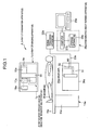
- Fig. 1 is an X-ray CT examination apparatus
- Fig. 2 is a sectional view of the X-ray CT examination apparatus
- Fig. 3 and Fig. 4 represent PET-X-ray CT examination apparatus.
- a nidus position specifying system for specifying a nidus position of an examinee 35 is constituted by a PET-X-ray CT examination apparatus "B" (see Fig. 3) and an X-ray CT examination apparatus "A" (see Fig. 1).
- the PET-X-ray CT examination apparatus B corresponds to a biological function examination apparatus and a first biological structure examination apparatus.
- the X-ray CT examination apparatus A corresponds to a second biological structure examination apparatus.
- the X-ray CT examination apparatus A contains an X-ray CT imaging apparatus 1a, an examinee holding apparatus 14a, a tomographic image forming apparatus 38a, and a display apparatus 29a.
- the tomographic image forming apparatus 38a contains a computer 27a (for example, workstation), and a storage apparatus 28a.
- the examinee holding apparatus 14a contains a supporting member 15a, and a bed 16a which is mounted on an upper edge portion of the supporting member 15a in such a manner that the bed 16a can be moved along a longitudinal direction thereof.
- the examinee 35 is laid on the bed 16a.
- this X-ray CT imaging apparatus 1a While the X-ray CT imaging apparatus 1a is installed along a direction perpendicular to the longitudinal direction of the bed 16a, this X-ray CT imaging apparatus 1a contains a radiation detector 80 (see Fig. 2), an X-ray source circumferential direction transporting apparatus 7a, a driving apparatus control apparatus 17a, an X-ray source control apparatus 18a, and a casing 36a (see Fig. 2). Also, the X-ray source circumferential direction transporting apparatus 7a is equipped with a disk-shaped holding apparatus 34, an X-ray source 9a, and an X-ray source apparatus holding unit 13a.
- the X-ray source apparatus holding unit 13a is mounted on an outer surface of the disk-shaped holding unit 34 at one edge portion of the disk-shaped holding unit 34.
- the X-ray source 9a is mounted on the other edge portion of the X-ray source apparatus holding unit 13a.
- the radiation detector 80, the X-ray source circumferential direction transporting apparatus 7a, the driving apparatus control apparatus 17a, and the X-ray source control apparatus 18a are installed in the casing 36a.
- the radiation detector 80 is arranged at a position where the radiation detector 80 can detect X-ray which has penetrated from the X-ray source 9a through the examinee 35.
- a plurality (approximately 100 pieces) of radiation detectors 80 are arrayed from the disk-shaped holding unit 34 via the detector holding unit 31, and are rotated around both the examinee holding apparatus 14a and the examinee 35 in conjunction with the X-ray source circumferential direction transporting apparatus 7a.
- a collimator 32 is mounted on the radiation detectors 80. Only X-rays generated from the X-ray source 9a are entered into the radiation detectors 80.
- the radiation detector 80 corresponds to a scintillation detector.
- the X-ray source 9a contains an X-ray tube which is not shown in the drawing, and is known in the field.
- an anode, a cathode, a current source of the cathode, and a voltage source which applies a voltage between the anode and the cathode are provided in an outer tube thereof.
- the cathode corresponds to a filament made of tungsten. Since a current is supplied from the current source to the cathode, electrons are emitted from the cathode.
- the electrons are accelerated by a voltage (140 KV) which is applied from the voltage source between the cathode and the anode, and then, the accelerated electrons impinge on the anode (made of W, Mo, and the like) corresponding to a target.
- a voltage 140 KV
- X-rays lower than, or equal to 140 KeV are generated by bombardments to the anode, and then, are emitted from the X-ray source 9a.
- the X-ray source control apparatus 18a controls emission time of X-rays emitted from the X-ray source 9a.
- the X-ray source control apparatus 18a repeatedly carries out such a control operation that during an X-ray CT examination, this X-ray source control apparatus 18a outputs an X-ray generating signal so as to close a switching device (will be referred to as "X-ray source switching device" hereinafter, and is not shown in this drawing) which is provided between the power supply and the anode (otherwise cathode) of the X-ray tube employed in the X-ray source 9a; when a first setting time has elapsed, the X-ray source control apparatus 18a outputs an X-ray stop signal so as to open the X-ray source switching device; and then, when a second setting time has elapsed, the X-ray source control apparatus 18a closes the X-ray source switching device.
- the voltage is applied between the anode and the cathode during the first setting time, whereas no voltage is applied between them during the second setting time. Since this control operation is carried out, the X-rays are emitted in a pulse shape from the X-ray tube.
- the driving apparatus control apparatus 17a When an X-ray CT examination is commenced, the driving apparatus control apparatus 17a outputs a drive starting signal so as to close a switching device (will be referred to as "first motor switching device” hereinafter) which is connected to the power supply. Since a current is supplied, a first motor is rotated, rotation force of this first motor is transferred via a driving force transferring mechanism to a pinion, and thus, this pinion is rotated. Since the pinion is rotated, the disk-shaped holding unit 34, namely the X-ray source 9a is transported around the examinee 35 at a setting speed. When the X-ray CT examination is ended, the driving apparatus control apparatus 17a outputs a drive stop signal so as to open the first motor switching device.
- a switching device (will be referred to as "first motor switching device” hereinafter) which is connected to the power supply. Since a current is supplied, a first motor is rotated, rotation force of this first motor is transferred via a driving force transferring mechanism to a pinion
- the transporting operation of the X-ray source 9a along the circumferential direction is stopped.
- the radiation detectors 80 are also fixed via the detector holding unit 31 to the disk-shaped holding unit 34, these radiation detectors 80 are rotated in combination with the X-ray source 9a.
- the X-rays are irradiated from the X-ray source 9a, it is so arranged that X-rays which have penetrated the examinee 35 can be measured by the radiation detectors 80.
- the supporting member 6a is installed on a floor of an examination room.
- the drive starting signal outputted from the drive apparatus control apparatus 17a is entered to the X-ray source control apparatus 18a.
- the X-ray source control apparatus 18a In response to the input of the drive starting signal, the X-ray source control apparatus 18a outputs an X-ray generating signal. Thereafter, the X-ray source control apparatus 18a repeatedly outputs both the X-ray stop signal and the X-ray generating signal. Since the X-ray stop signal and the X-ray generating signal are repeatedly outputted, the X-ray source 9a emits X-rays during a setting time (for example, 1 ⁇ sec.), and thereafter, stops the emission of the X-rays.
- a setting time for example, 1 ⁇ sec.
- Both the emitting operation and the stopping operation of the X-rays are repeatedly carried out during transporting time period of the X-ray source 9a along the circumferential direction.
- the X-rays emitted from the X-ray source 9a are irradiated to the examinee 35 located in a hole unit 30a in a fan-beam shape. Since the X-ray source 9a is transported along the circumferential direction, the examinee 35 on the bed 16 is irradiated by the X-rays from the peripheral portion thereof.
- the X-rays which has passed through the examinee 35 are detected by the radiation detector 80 which is located at a position opposite to the X-ray source 9a at an angle of 180 degrees along the opposite direction while an axial center of the hole unit 30a is set as a base point, and is rotated in a similar manner to the X-ray source 9a.
- These radiation detectors 80 output detection signals of the X-rays (will be referred to as "X-ray detection signals" hereinafter).
- the X-ray detection signals are transferred via relevant wiring lines 23a to the signal processing apparatus 22a corresponding thereto.
- the signal processing apparatus 22a calculates intensity of the X-ray detection signals based upon the entered X-ray detection signals, and then, outputs the intensity information.
- the intensity information of the X-ray detection signals outputted from the signal processing apparatus 22a is stored via the computer 27a to the storage apparatus 28a.
- the PET-X-ray CT examination apparatus B is equipped with an imaging apparatus 1, an examinee holding apparatus 14, a signal processing apparatus 37, a tomographic image forming apparatus 38, and a display apparatus 29.
- the signal processing apparatus 37 contains a signal discriminating apparatus 19 and a simultaneous counting apparatus 26.
- the tomographic image forming apparatus 38 contains a computer 27 (for instance, workstation) and a storage apparatus 28.
- the examinee holding apparatus 14 contains a supporting member 15, and a bed 16 which is mounted on an upper edge portion of the supporting member 15 in such a manner that the bed 16 can be moved along a longitudinal direction thereof.
- this imaging apparatus 1 While the imaging apparatus 1 is installed along a direction perpendicular to the longitudinal direction of the bed 16, this imaging apparatus 1 contains a radiation detector ring-shaped member 3, an X-ray source circumferential direction transporting apparatus 7, a driving apparatus control apparatus 17, an X-ray source control apparatus 18, and a casing 36.
- the radiation detector ring-shaped member 3, the X-ray source circumferential direction transporting apparatus 7, the driving apparatus control apparatus 17, and the X-ray source control apparatus 18 are installed inside the casing 36.
- the radiation detector ring-shaped member 3 contains a ring-shaped holding unit 5, and a large number of radiation detectors 4 which are installed in a ring shape inside the ring-shaped holding unit 5.
- a hole unit 30 is formed inside the radiation detectors 4 of the radiation detector ring-shaped member 3.
- the hole unit 30 is made of a through hole, and corresponds to an observation region into which the bed 16 is inserted.
- a large number of radiation detectors 4 (approximately 10,000 pieces in total) are arranged in the form of plural arrays in such a manner that these radiation detectors 4 are installed on the ring-shaped holding unit 5 not only along the circumferential direction, but also along the axial direction of the hole unit 30.
- the radiation detector 4 corresponds to a semiconductor radiation detector, while a semiconductor element portion thereof is constructed of CdTe (cadmium tellurium) which is made of a cube sized by 5 mm X 5 mm and corresponds to a detecting portion thereof.
- this element portion may be constituted by either GaAs (gallium arsenide) or CZT (cadmium zinc tellurium).
- the ring-shaped holding unit 5 is installed on the supporting member 6.
- the supporting members 6 and 15 are installed on a floor of an examination room.
- Both the driving apparatus control apparatus 17 and the X-ray source control apparatus 18 are installed inside the casing 36 in combination with the ring-shaped holding unit 5.
- a guide rail 12 is formed in the form of a concave in one edge surface of the casing 36.
- the guide rail 12 has a ring shape and surrounds a peripheral portion of the hole unit 30.
- the X-ray source apparatus 8 contains an X-ray source 9, the X-ray source driving apparatus 10, and an axial direction transporting arm 11.
- the X-ray source driving apparatus 10 is equipped with a first motor and a power transferring mechanism (none of them is shown) within the casing 10A.
- the power transferring mechanism is coupled to a rotation shaft of the first motor.
- the telescopically-drivable axial direction transporting arm 11 is mounted on the casing 10A of the X-ray source driving apparatus 10, and is extended to the inside portion of the hole unit 30.
- the X-ray source 9 is mounted on the axial direction transporting arm 11.
- the axial direction transporting arm 11 is telescopically driven by a second motor (not shown) installed in the X-ray source driving apparatus 10.
- the X-ray source driving apparatus 10 is mounted on the guide rail 12 in such a manner that this X-ray source driving apparatus 10 is not dropped, but can be transported along the guide rail 12.
- the X-ray source driving apparatus 10 owns a pinion. This pinion is meshed with a rack provided on the guide rail 12 so as to receive rotation force from the power transferring mechanism.
- the X-ray source 9 contains an X-ray tube which is known in this field.
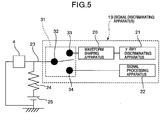
- the respective radiation detectors 4 are connected by respective wiring lines 23 to movable terminals 32 (see Fig. 5) of the corresponding signal discriminating apparatus 19.
- the signal discriminating apparatus 19 are provided with the respective radiation detectors 4 one by one.
- a detailed structure of one signal discriminating apparatus 19 is indicated in Fig. 5.
- This signal discriminating apparatus 19 is equipped with a switch 31, a waveform shaping apparatus 20, a ⁇ -ray discriminating apparatus 21, and a signal processing apparatus 22 for acquiring intensity of X-rays.
- the switch 31 contains the movable terminal 32, and two fixed terminals 33 and 34.
- the waveform shaping apparatus 20 is connected to both the fixed terminal 33 and the ⁇ -ray discriminating apparatus 21.
- the signal processing apparatus 22 is connected to the fixed terminal 34.
- a power supply 25 is connected to the wiring line 23 and the radiation detector 4.
- the ⁇ -ray discriminating apparatus 21 is connected via a simultaneous counting apparatus 26 to a computer 27.
- a total number of the simultaneous counting apparatus 26 is 1, and is connected to all of the ⁇ -ray discriminating apparatuses 21.
- Each of the signal processing apparatus 22 is connected to the computer 27.
- Both the storage apparatus 28 and the display apparatus 29 are connected to the computer 27.
- the signal discriminating apparatus 19 is equipped with an X-ray detection signal processing apparatus containing the signal processing apparatus 22, and a ⁇ -ray detection signal processing apparatus containing both the waveform shaping apparatus 20 and the ⁇ -ray discriminating apparatus 21.
- a concrete X-ray CT examination and a concrete PET examination, which are executed by the imaging apparatus 1, will now be described.
- a chemical PET drug is injected into the examinee 35 in order that injected body interior radiation becomes equal to 370 MBq.
- the chemical PET drug is selected in accordance with a purpose of examination (place of cancer is grasped, cardiac arteria stream is examined, etc.). After the chemical PET drug has been injected and a predetermine time period has elapsed, while the examinee 35 is laid on the bed 16, this examinee 35 is inserted into the hole unit 30.
- the X-ray source control apparatus 18 controls emission time of X-rays emitted from the X-ray source 9.
- this X-ray source control apparatus 18 repeatedly carries out such a control operation that during an X-ray CT examination, this X-ray source control apparatus 18 outputs an X-ray generating signal so as to close a switching device (will be referred to as "X-ray source switching device" hereinafter, and is in drawing) which is provided between the power supply and the anode (otherwise cathode) of the X-ray tube employed in the X-ray source 9; when a first setting time has elapsed, the X-ray source control apparatus 18 outputs an X-ray stop signal so as to open the X-ray source switching device; and then, when a second setting time has elapsed, the X-ray source control apparatus 18 closes the X-ray source switching device.
- the voltage is applied between the anode and the cathode during the first setting time, whereas no voltage is applied between them during the second setting time. Since this control operation is carried out, the X-rays are emitted in a pulse shape from the X-ray tube.
- An irradiation time "T" corresponding to the first setting time is set to be, for example, 1 ⁇ sec in order that detection probability of ⁇ rays (gamma rays) on the radiation detectors 4 can be neglected.
- the second setting time corresponds to such a time that the X-ray source 9 is moved between one radiation detector 4 and another radiation detector 4 which is located adjacent to the first-mentioned radiation detector 4 along the circumferential direction. This second setting time is determined based upon a moving speed of the X-ray source 9 along the circumferential direction of the guide rail 12. Both the first setting time and the second setting time have been stored in the X-ray source control apparatus 18.
- the driving apparatus control apparatus 17 When an X-ray CT examination is commenced, the driving apparatus control apparatus 17 outputs a drive starting signal so as to close a switching device which is connected to the first motor of the X-ray source driving apparatus 10 so a to be connected to the power supply. Since a current is supplied, the first motor is rotated, rotation force of this first motor is transferred via a driving force transferring mechanism to a pinion, and thus, this pinion is rotated. Since the pinion is rotated, the X-ray source apparatus 8, namely the X-ray source 9 is transported around the peripheral area of the examinee 35 at a setting speed along the guide rail 12. When the X-ray CT examination is ended, the driving apparatus control apparatus 17 outputs a drive stop signal so as to open the above-described switching device. As a result, the transporting operation of the X-ray source 9 along the circumferential direction is stopped.
- all of the radiation detectors 4 which are arranged in the ring shape along the circumferential direction are not moved along the circumferential direction thereof, but also, are not moved along the axial direction of the hole unit 30.
- the control signal is transferred from both the X-ray source control apparatus and the driving apparatus control apparatus, which are not moved, to the X-ray source apparatus which is moved. This technical idea never disturbs the transportation of the X-ray source apparatus.
- a drive starting signal outputted from the drive apparatus control apparatus 17 is entered to the X-ray source control apparatus 18.
- the X-ray source control apparatus 18 In response to the input of the drive starting signal, the X-ray source control apparatus 18 outputs an X-ray generating signal. Thereafter, the X-ray source control apparatus 18 repeatedly outputs both the X-ray stop signal and the X-ray generating signal. Since the X-ray stop signal and the X-ray generating signal are repeatedly outputted, the X-ray source 9 emits X-rays during the first setting time (for example, 1 ⁇ sec.), and thereafter, stops the emission of the X-rays during the second setting time.
- the first setting time for example, 1 ⁇ sec.
- Both the emitting operation and the stopping operation of the X-rays are repeatedly carried out during transporting time period of the X-ray source 9 along the circumferential direction.
- the X-rays emitted from the X-ray source 9 are irradiated to the examinee 35 located in the hole unit 30 in a fan-beam shape. Since the X-ray source 9 is transported along the circumferential direction, the examinee 35 on the bed 16 is irradiated by the X-rays from the peripheral portion thereof.
- the X-rays which has passed through the examinee 35 are detected by a plurality of radiation detectors 4 which are located at positions opposite to the X-ray source 9 at an angle of 180 degrees along the opposite direction while these plural radiation detectors 4 are positioned at a center in the circumferential direction.
- These radiation detectors 4 output detection signals of the X-rays (will be referred to as "X-ray detection signals” hereinafter).
- the X-ray detection signals are transferred via relevant wiring lines 23a to the signal discriminating apparatuses 19 corresponding thereto. It should be noted that these radiation detectors 4 which detect the above-explained X-rays will be referred to as "first radiation detectors 4" for the sake of convenience.
- Gamma ( ⁇ ) rays of 511 KeV which are caused by the chemical PET drug are being emitted from the examinee 35 located inside the hole unit 30.
- the radiation detectors 4 other than the first radiation detectors 4 detect the ⁇ rays, and then, outputs detection signals of these ⁇ rays (will be referred to as " ⁇ -rays detection signals” hereinafter).
- the ⁇ -rays detection signals are entered via the relevant wiring lines 23 to the respective signals discriminating apparatus 19.
- Such radiation detectors 4 which are detecting the ⁇ rays will be referred to as "second radiation detectors 4" for the sake of convenience.
- the ⁇ -rays detection signals outputted from the second radiation detectors 4 are transferred to the ⁇ -rays discriminating apparatus 21, and the X-ray detection signals outputted from the first radiation detectors 4 are transferred to the signal processing apparatus 22 within the signal discriminating apparatus 19.
- Such a transfer operation of the respective detection signals is carried out by selectively switching the switch 31 of the signal discriminating apparatus 19.
- a switching operation for connecting the movable terminal 32 of the switch 31 to either the fixed terminal 33 or the fixed terminal 34 is carried out in response to a switching control signal which corresponds to the output signal of the driving apparatus control apparatus 17.
- the driving apparatus control apparatus 17 controls the transporting operation of the X-ray source apparatus 10.
- this driving apparatus control apparatus 17 selects the first radiation detectors 4, and connects the movable terminal 32 of the switch 31 to the fixed terminal 34 thereof in the signal discriminating apparatus 19 which is connected to this first radiation detector 4.
- An encoder (not shown) is coupled to the first motor provided in the X-ray source driving apparatus 10.
- the driving apparatus control apparatus 17 inputs thereinto a detection signal of the encoder so as to acquire a position of the X-ray source driving apparatus 10, namely, a position of the X-ray source 9 along the circumferential direction, and selects such a radiation detector 4 which is located at a position opposite to this acquired position of the X-ray source 9 at an angle of 180 degrees by employing the positional data of the respective radiation detectors 4 which have been stored.
- the driving apparatus control apparatus 17 selects these plural pieces of the radiation detectors 4. These radiation detectors 4 correspond to the first radiation detectors.
- the first radiation detectors 4 are also different from each other in connection with the transportation of the X-ray source 9 along the circumferential direction. It is so observed that the first radiation detectors 4 are also moved along the circumferential direction in a quasi-manner in connection with the transportation of the X-ray source 9 along the circumferential direction.
- movable terminals 32 connected to such radiation detectors 4 which newly become the first radiation detectors 4 are connected to the fixed terminals 34.
- the movable terminals 32 which are connected to the radiation detectors 4 which have not become the first radiation detectors 4 in connection with the transportation of the X-ray source 9 along the circumferential direction are connected to the fixed terminals 33 by the driving apparatus control apparatus 17.
- the first radiation detectors 4 may correspond to such radiation detectors 4 which are connected to the signal processing apparatus 22 by the switch 31.
- the second radiation detectors 4 may correspond to such radiation detectors 4 which are connected to the ⁇ -ray discriminating apparatus 21 by the switch 31.
- the respective radiation detectors 4 which are installed in the ring-shaped holding unit 5 may constitute the first radiation detectors 4 in one case, and may constitute the second radiation detectors 4 in another case, depending upon a positional relationship with respect to the X-ray source 9.
- one radiation detector 4 may output both an X-ray detection signal and a ⁇ -ray detection signal, although these X-ray detection signal and ⁇ -ray detection signal are temporally separately outputted.
- the first radiation detectors 4 detect such X-rays which have been irradiated from the X-ray source 9 and then have penetrated through the examinee 35 during 1 ⁇ sec equal to the first setting time. The probability is negligibly small at which the first radiation detectors 4 detect ⁇ rays emitted from the examinee 35 during 1 ⁇ sec. A large number of ⁇ rays which have been generated within the interior portion of the examinee 35 due to the chemical PET drug are not emitted along a specific direction, but are emitted along a universal direction.
- these ⁇ rays are emitted in such a condition that these ⁇ rays constitute paired ⁇ rays, and the paired ⁇ rays are emitted along directions substantially opposite to each other (180 degrees ⁇ 0.6 degrees), and then, are detected by way of the second radiation detectors 4 of the radiation detector ring-shaped member 4.
- the X-ray detection signal outputted from the first radiation detector 4 is inputted into the signal processing apparatus 22 by way of the switch 31.
- the signal processing apparatus 22 calculates intensity of the X-ray detection signal based upon the inputted X-ray detection signal, and then, outputs this calculated intensity information.
- the ⁇ -ray detection signal outputted from the second radiation detector 4 is inputted to the waveform shaping apparatus 20 by way of the switch 31.
- the waveform shaping apparatus 20 converts the inputted ⁇ -ray detection signal into such a ⁇ -ray detection signal having a Gaussian distribution waveform, and then, outputs this converted ⁇ -ray detection signal.
- energy of such ⁇ rays is equal to 511 KeV, which are produced in the interior body of the examinee 35, since positrons emitted from the chemical PET drug are annihilated.
- all of the energy of the ⁇ rays within the semiconductor element portion are not always changed into electrons.
- the ⁇ -ray discriminating apparatus 21 defines energy of e.g., 450 KeV lower than 511 KeV as an energy setting value, when an imaging signal having energy higher than, equal to this energy setting value (will be referred to as "first energy setting value") is inputted into the ⁇ -ray discriminating apparatus 21, this ⁇ -ray discriminating apparatus 21 generates a pulse signal having predetermined energy.
- the ⁇ -ray discriminating apparatus 21 corresponds to such an apparatus for generating the pulse signal having the above-described energy when such an imaging signal (namely, ⁇ -ray detection signal) having energy higher than, or equal to the first energy setting value is inputted thereinto.
- a filter capable of penetrating therethrough imaging signals having a predetermined energy range may be alternatively provided within the ⁇ -ray discriminating apparatus 21 (otherwise, prestage of ⁇ -ray discriminating apparatus 21).
- the ⁇ -ray discriminating apparatus 21 generates a pulse signal with respect to an imaging signal which has passed a first filter.
- the simultaneous counting apparatus 26 performs a simultaneous counting operation every ⁇ -ray pair in such a manner that the pulse signals outputted from the ⁇ -ray discriminating apparatuses 21 of the respective signal discriminating apparatuses 19 are entered into this simultaneous counting apparatus 26, and these inputted pulse signals are employed, and then, calculate a count value with respect to the ⁇ -ray detection signal. Furthermore, the simultaneous counting apparatus 26 processes two detection points where each of ⁇ rays of a ⁇ -ray pair have been detected based upon one pair of pulse signals with respect to the ⁇ -ray pair so as to produce data as the ⁇ -ray detection positional information. It should be understood that the above-described two detection points imply such positions of one paired radiation detectors 4 whose directions are different from each other at an angle of approximately 180 degrees while the axial center of the hole unit 30 is set as the center.
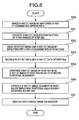
- an X-ray CT image of the examinee 35 is imaged by employing the X-ray CT examination apparatus A (step S50), and then an image reconstructing operation of the data acquired by the X-ray CT examination apparatus A is carried out (step S51).
- both a PET image and an X-ray CT image as to the examinee 35 are imaged by employing the PET-X-ray CT examination apparatus B (step S52), and then, both the PET data and the X-ray CT data acquired by the PET-X-ray CT examination apparatus B are image-reconstructed so as to acquire both a PET image and an X-ray CT image (step S53).
- the image reconstructing operation of this X-ray CT image is identical to that of the above-described step S51.
- a PET image reconstructing method in the case of a two-dimensional imaging operation, for example, the above-explained Filtered Back Projection Method may be employed.
- an image reconstructing operation is carried out by employing, for example, "Fourier ---???" method which is described in IEEE Transactions on Medical Imaging, volume No. 16, page 145, in 1997.
- a PET image is acquired.
- generation density information of gamma ray pairs is acquired.
- the imaging operation by the X-ray CT examination apparatus A has been first of all carried out in this first embodiment.
- the imaging operation (step S52) by the PET-X-ray CT examination apparatus B may be executed in advance, and thereafter, the image reconstructing operations may be carried out in this order of the steps S53, S50, S51.
- the process operations defined in the steps S51 and S53 are carried out by the computer, the process operations defined in the steps S51 and S53 may be alternatively carried out in a parallel manner.
- the process operations defined in the steps S50 and S53 may be carried out in a parallel manner. Also, after both the imaging operations have been accomplished, image reconstructing operations (namely, steps S51 and S53) may be simultaneously carried out, or may be sequentially carried out.
- the X-ray CT image acquired from the X-ray CT examination apparatus A is compared with the X-ray CT image acquired from the PET-X-ray CT image by an X-ray CT image positional alignment computer so as to clarify a positional relationship between both these X-ray CT images (step S54).
- both the X-ray CT image acquired in the step S51 and an X-ray CT image which is positionally aligned must be entered into the X-ray CT image positional alignment computer.
- These X-ray images are inputted by employing, for instance, an internal hospital network so as to transfer data files, or employing a storage medium such as an MO disk.
- an image comparing operation may be carried out by employing such shapes which are clearly present in X-ray CT images. For instance, a bone is clearly imaged in an X-ray CT image.
- X-ray CT images of the lung fields are not matched with each other by merely moving, rotating, enlarging, and compressing these X-ray CT images.
- a non-linear transformation is employed.
- this non-linear transformation there is a deformable model.
- the free form deformations may be employed which is described in IEEE Transactions of Medical Imaging, volume No. 18, page 712.
- This method corresponds to such a method for using a deformable model in which a large movement of an examinee is expressed by employing an affine transformation (transformation by rotation, parallel movement, and enlarge/compression), whereas a local movement is expressed by employing a beta spline function.
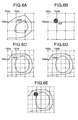
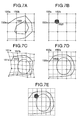
- FIG. 6A-6E A correcting method is represented by employing Figs. 6A-6E.
- Figs. 6A-6E it is so assumed that a positional relationship between Fig. 6A and Fig. 6C can be grasped since the process operation of the step S54 of Fig. 8 is executed, and furthermore, a positional relationship between Fig. 6A and Fig. 6B can be obtained since the same imaging operation is carried out.
- such an assumption is established: points 151a, 151b, 151e, and 151f of an image shown in Fig.
- FIG. 6C correspond to points 150a, 150b, 150e, and 150f of an image shown in Fig. 6A, respectively, and furthermore, since the simultaneous imaging operations are carried out, points 152a, 152b, 152e, and 152f of an image indicated in Fig. 6B correspond to the points 150a, 150b, 150e, and 150f of the image shown in Fig. 6A, respectively. Also, it is so assumed that resolution of the image shown in Fig. 6C is higher than that of the image shown in Fig. 6A.
- both the PET image and the X-ray CT image may be displayed in a simultaneous manner, or may be alternatively displayed side by side. As a result, the below-mentioned effect may be achieved.
- the precision of the biological structure image which is required so as to grasp the nidus position of the PET image can be obtained by a small amount of data.
- the simultaneous imaging operation capable apparatus PET-X-ray CT examination apparatus B
- PET-X-ray CT examination apparatus B the simultaneous imaging operation capable apparatus of both the PET examination apparatus and the X-ray CT examination apparatus.
- simultaneous imaging operations are not necessarily required.
- a second embodiment of the present invention in such a case that both a PET examination apparatus and an X-ray CT examination apparatus are arrayed so as to acquire a positional relationship will now be described with reference to Fig. 9 to Fig. 11.
- An imaging sequential operation of the second embodiment is not basically different from the imaging sequential operation shown in Fig. 8 of the first embodiment.
- an imaging operation is carried out in a parallel PET-X-ray CT examination apparatus "C" capable of grasping a positional relationship.
- a flow chart in which this step S52 has been changed into a step S552 is indicated in Fig. 10.
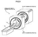
- the parallel PET-X-ray CT examination apparatus "C” used in the step S552 is explained with reference to Fig. 9.
- both an X-ray CT examination apparatus 100 and a PET examination apparatus 101 are arranged in a parallel manner.
- a positional relationship between the X-ray CT examination apparatus 100 and the PET examination apparatus 101 is known, and a positional alignment between these examination apparatuses 100 and 101 can be readily performed.
- An imaging method of the X-ray CT examination apparatus 100 is similar to that of the X-ray CT examination apparatus "A" described in the first embodiment.
- a radiation detector ring-shaped member 3 is installed in a casing 36.
- the radiation detector ring-shaped member 3 contains a ring-shaped holding unit 5, and a large number of radiation detectors 4 which are installed in a ring shape inside the ring-shaped holding unit 5.
- a hole unit 30 is formed inside the radiation detectors 4 of the radiation detector ring-shaped member 3.
- the hole unit 30 is made of a through hole, and corresponds to an observation region into which the bed 16 is inserted.
- a large number of radiation detectors 4 are arranged in the form of plural arrays in such a manner that these radiation detectors 4 are installed on the ring-shaped holding unit 5 not only along the circumferential direction, but also along the axial direction of the hole unit 30.
- the radiation detector 4 corresponds to a semiconductor radiation detector, while a semiconductor element portion thereof is constructed of CdTe (cadmium tellurium) which is made of a cube sized by 5 mm X 5 mm and corresponds to a detecting portion thereof.
- this element portion may be constituted by either GaAs (gallium arsenide) or CZT (cadmium zinc tellurium).
- the respective radiation detectors 4 are connected to respective waveform shaping apparatuses 20 corresponding thereto. These waveform shaping apparatuses 20 are provided one by one with respect to each of the radiation detectors 4.
- the waveform shaping apparatuses 20 are connected to the respective radiation detectors 4 and ⁇ -ray discriminating apparatuses 21.
- the ⁇ -ray discriminating apparatus 21 is connected via a simultaneous counting apparatus 26 to a computer 27. A total number of the simultaneous counting apparatus 26 is 1, and is connected to all of the ⁇ -ray discriminating apparatuses 21.
- Both a storage apparatus 28 and a display apparatus 29 are connected to the computer 27.
- a chemical PET drug is injected into the examinee 35 in order that injected body interior radiation becomes equal to 370 MBq.
- the chemical PET drug is selected in accordance with a purpose of examination (place of cancer is grasped, cardiac arteria stream is examined, etc.). After the chemical PET drug has been injected and a predetermine time period has elapsed, while the examinee 35 is laid on the bed 16, this examinee 35 is inserted into the hole unit 30.
- Gamma rays of 511 KeV which are caused by the chemical PET drug are being emitted from the examinee 35 located within the hole unit 30.
- the radiation detectors 4 other than the first radiation detectors 4 detect these gamma rays emitted from the examinee 35, and output detection signals of these gamma rays (will be referred to as " ⁇ -ray detection signals" hereinafter).
- the ⁇ -ray detection signals are transferred via the relevant wiring lines 23 and the corresponding waveform shaping apparatuses 20 to the ⁇ -ray discriminating apparatuses 21.
- a large number of ⁇ rays which have been generated within the interior portion of the examinee 35 due to the chemical PET drug are not emitted along a specific direction, but are emitted along a universal direction.
- these ⁇ rays are emitted in such a condition that these ⁇ rays constitute paired ⁇ rays, and the paired ⁇ rays are emitted along directions substantially opposite to each other (180 degrees ⁇ 0.6 degrees), and then, are detected by any of the radiation detectors 4 of the radiation detector ring-shaped member 3.
- the ⁇ -ray detection signals detectors 4 are entered into the waveform shaping apparatuses 20.
- the waveform shaping apparatuses 20 shape the waveforms obtained in the radiation detectors 4 so as to produce such waveforms which can be read by the ⁇ -ray discriminating apparatus 21.
- the output signals of the waveform shaping apparatus 20 are supplied to the ⁇ -ray discriminating apparatuses 21.
- a role of this ⁇ -ray discriminating apparatus 21 will now be described.
- energy of such ⁇ rays is equal to 511 KeV, which are produced in the interior body of the examinee 35, since positrons emitted from the chemical PET drug are annihilated.
- all of the energy of the ⁇ rays within the semiconductor element portion are not always changed into electrons.
- the ⁇ -ray discriminating apparatus 21 defines energy of e.g., 450 KeV lower than 511 KeV as an energy setting value, when an imaging signal having energy higher than, equal to this energy setting value (will be referred to as "first energy setting value") is inputted into the ⁇ -ray discriminating apparatus 21, this ⁇ -rays discriminating apparatus 21 generates a pulse signal having predetermined energy.
- the ⁇ -ray discriminating apparatus 21 corresponds to such an apparatus for generating the pulse signal having the above-described energy when such an imaging signal (namely, ⁇ -ray detection signal) having energy higher than, or equal to the first energy setting value is inputted thereinto.
- a filter capable of penetrating therethrough imaging signals having a predetermined energy range may be alternatively provided within the ⁇ -ray discriminating apparatus 21 (otherwise, prestage of ⁇ -ray discriminating apparatus 21).
- the ⁇ -ray discriminating apparatus 21 generates a pulse signal with respect to an imaging signal which has passed a first filter.
- the simultaneous counting apparatus 26 performs a simultaneous counting operation every ⁇ -ray pair in such a manner that the pulse signals outputted from the ⁇ -ray discriminating apparatuses 21 are entered into this simultaneous counting apparatus 26, and these inputted pulse signals are employed, and then, calculates a count value with respect to the ⁇ -ray detection signal. Furthermore, the simultaneous counting apparatus 26 processes two detection points where each of ⁇ -rays of a ⁇ -ray pair have been detected based upon one pair of pulse signals with respect to the ⁇ -ray pair so as to produce data as the ⁇ -ray detection positional information.
- the above-described two detection points imply such positions of one paired radiation detectors 4 whose directions are different from each other at an angle of approximately 180 degrees while the axial center of the hole unit 30 is set as the center.
- the positional information outputted from the simultaneous counting apparatus 26 is stored in the storage apparatus 28.
- both a PET image and an X-ray CT image are acquired in a step S552.
- the data obtained in the parallel PET-X-ray CT examination apparatus C is image-reconstructed so as to obtain a PET image and a CT image (step S53).
- the image reconstructing operation of this second embodiment is identical to that of the first embodiment.
- a positional alignment may be carried out in a similar manner to that of the first embodiment.
- a positional relationship between the PET examination apparatus and the X-ray CT examination apparatus cannot be completely grasped.
- a positional relationship between the PET examination apparatus and the X-ray CT examination apparatus cannot be completely grasped.
- a positional relationship between the PET image and the X-ray CT image is acquired from the positional relationship between the PET examination apparatus and the X-ray CT examination apparatus. For instance, assuming now that centers of these PET and X-ray CT examination apparatus are separated by an X cm, when the bed 16 is moved over a distance of X cm, the positions are matched with each other.
- the positional alignment is carried out by utilizing this technical idea. If only the positional relationship between the PET image and the X-ray CT image can be grasped, then the succeeding process operation may be carried out in a similar manner to that of the first embodiment.
- the below-mentioned effect may be furthermore achieved.
- the positional alignment can be carried out with respect to an X-ray CT examination apparatus having high spatial resolution.
- this third embodiment describes such a method for synthesizing sinogram data preceding to the above-explained images, and images in a frequency space.
- These positional alignments may become very effective in the case that there are different filters when image reconstructing operations of apparatus are carried out. This is because images themselves are different from each other in such a case that various sorts of filters are employed when an image reconstructing operation is carried out, and/or in such a case that different image reconstructing methods are employed. As a consequence, it is very important that a positional alignment is carried out by employing a sinogram.
- This third embodiment will be described as follows:
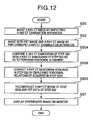
- the X-ray CT sinogram acquired in the step S50 is compared with the X-ray CT sinogram acquired in the step S52 so as to perform a positional alignment (step S554).
- Data acquired before an image reconstructing operation is referred to as a sinogram, and corresponds to data in an r- ⁇ space. Since information as to each voxel in a sinogram is expressed by a curve, both a featured curve contained in the X-ray CT data acquired in the step S50 and a featured curve contained in the X-ray CT data acquired in the step S52 are extracted, and then, a positional alignment is carried out in such a manner that the positions of these featured curves are overlapped to each other.
- step S556 data of low resolution CT is corrected based upon data of high resolution CT.
- step S553 the corrected X-ray CT data of the PET-X-ray CT and the PET data thereof are image-reconstructed.
- the positional relationship between these X-ray CT and PET data obtained after the image reconstruction is already known since the simultaneous imaging operation is carried out, so that this positional relationship has been obtained. Accordingly, an image synthesizing operation is carried out by employing the known positional relationship (step S57).
- the positional aligning method on the sinogram has been disclosed.
- the positional aligning method may be carried out even in such a frequency space that the sinogram data is Fourier-transformed.
- the below-mentioned merit can be obtained in addition to the merits achieved in the first embodiment and the second embodiment.
- the interpolating operations have been carried out in all of the regions.
- a region of interest is present only in a portion of an image.
- the image may be compressed.
- this technical idea is utilized, such a method for processing only a necessary image portion in high precision is represented.
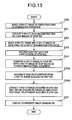
- Fig. 13 is a flow chart for describing an imaging operation of this fourth embodiment.
- steps defined from S50 to S53 are similar to those of the first embodiment.
- a region of interest by a user is set by employing the X-ray CT image acquired in the step S53 (step S555).
- the following methods may be conceived: a manual extracting method, an automatic extracting method, and a semi-automatic extracting method.
- the user performs a marking operation on the region of interest of the X-ray CT image.
- the user surrounds the region of interest on a console screen by operating an input apparatus such as a mouse.
- a computer determines the region of interest based upon the input data from the user.
- the user selects the region of interest, or previously informs the region of interest to the computer.
- the computer extracts a liver region.
- an extracting method there is the following extracting method. That is, for example, since a range of CT values of a liver has been previously determined, the computer applies a threshold value to an X-ray CT image so as to extract the liver. Also, as the semi-automatic extracting method, there is a region growing method.
- the computer automatically calculates such a region which is approximated to the marking CT value so as to determine the region of interest.
- the computer requests the user to confirm as to whether or not the region is correctly extracted in order to avoid a misdiagnosis.
- step S56 of the first embodiment the correcting operation executed in the step S56 of the first embodiment is carried out as to only the extracted portion (step S566). Since the correcting method is similar to that of the first embodiment, explanations thereof are omitted. Then, thereafter, an image is displayed in a step S57. As a result, the below-mentioned effect can be furthermore achieved in addition to the effects obtained in the first to third embodiments.
Landscapes
- Engineering & Computer Science (AREA)
- Health & Medical Sciences (AREA)
- Life Sciences & Earth Sciences (AREA)
- Medical Informatics (AREA)
- Physics & Mathematics (AREA)
- Biomedical Technology (AREA)
- Animal Behavior & Ethology (AREA)
- Biophysics (AREA)
- High Energy & Nuclear Physics (AREA)
- Veterinary Medicine (AREA)
- Nuclear Medicine, Radiotherapy & Molecular Imaging (AREA)
- Optics & Photonics (AREA)
- Pathology (AREA)
- Radiology & Medical Imaging (AREA)
- Public Health (AREA)
- Heart & Thoracic Surgery (AREA)
- Molecular Biology (AREA)
- Surgery (AREA)
- General Health & Medical Sciences (AREA)
- Theoretical Computer Science (AREA)
- Computer Vision & Pattern Recognition (AREA)
- General Physics & Mathematics (AREA)
- Human Computer Interaction (AREA)
- Pulmonology (AREA)
- Apparatus For Radiation Diagnosis (AREA)
- Nuclear Medicine (AREA)
- Magnetic Resonance Imaging Apparatus (AREA)
- Measuring And Recording Apparatus For Diagnosis (AREA)
- Image Processing (AREA)
- Image Analysis (AREA)
Abstract
An X-ray CT image (FIG. 6A) of a low spatial resolution image is acquired by employing a PET-X-ray CT examination apparatus "B." Also, a PET image (FIG. 6B) is acquired by employing the PET-X-ray CT examination apparatus "B." Furthermore, an X-ray CT image (FIG. 6C) of a high spatial resolution image is acquired by employing another X-ray CT examination apparatus "A." Then, the X-ray CT image (FIG. 6A) equal to the low spatial resolution image is corrected by employing the X-ray CT image (FIG. 6C), so that an X-ray CT image (FIG. 6D) equal to a high spatial resolution image is obtained. Since a positional relationship of the resulting X-ray CT image (FIG. 6D) with respect to the PET image (FIG. 6B) can be grasped, this PET image (FIG. 6B) can be simply synthesized with the X-ray CT image (FIG. 6D) like an image (FIG. 6E). <IMAGE>
Description
The present invention is related to a nidus
position specifying system and a radiation examination
apparatus with employment of an X-ray CT examination
apparatus, a PET examination apparatus, a SPECT
examination apparatus, and the like.
As techniques capable of imaging biological
functions and biological structures of interior
portions of examinees in a non-invasive manner, there
are examinations using radiation. X-ray CT, MRI, PET,
SPECT examination apparatuses are available as a
typical radiation examination apparatus.
An X-ray CT (Computerized Tomography) imaging
method corresponds to such a method that radiation
emitted from an X-ray source is irradiated to an
examinee, and a biological structure of an interior
portion of this examinee is imaged based upon
transmission of the radiation penetrated through the
interior portion of the examinee. Since intensity of
X-rays which have passed through the interior portion
is detected by a radiation detecting element, a linear
attenuation coefficient between the X-ray source and
the radiation detecting element may be acquired. This
linear attenuation coefficient is processed by
employing a Filtered Back Projection Method described
in a non-patent publication 1 so as to calculate a
linear attenuation coefficient of each of voxels, and
then, this calculated linear attenuation coefficient is
converted into a CT value. In medical activities, a
radiation source which is usually employed in an X-ray
CT is approximated to maximum 140 keV, average 80 keV.
An MRI (Magnetic Resonance Imaging) method
corresponds to such a method for imaging a biological
structure of an interior portion of an examinee by
utilizing radio waves and magnets such as a permanent
magnet and an electromagnetic magnet. Elements whose
proton numbers, or neutron numbers are odd numbers own
inherent magnetic moment, and may induce resonant
phenomena caused by external static magnetic fields.
While an atom which may represent a maximum sensitivity
with respect to an external magnetic field is a
hydrogen atom, a large number of hydrogen molecules
such as organic molecules having water and hydrogen
atoms are present in an interior body of a human.
Under such a circumstance, an examinee is arranged in a
strong magnetic field, and then, radio waves having a
specific frequency are irradiated to the examinee under
such a condition that spin directions of hydrogen
elements are made coincident with a constant direction.
As a result, the radio waves and the hydrogen elements
induce a resonant phenomenon, so that electromagnetic
waves are generated. Since the electromagnetic waves
are received by a coil so as to be processed by a
computer, an interior distribution image of the
hydrogen atoms may be acquired. This interior
distribution image is referred to as an MRI image.
A PET examination corresponds to such an
examination method that while a positron emitting
nuclide is applied to a chemical drug and this chemical
drug is injected to an examinee, a check is made that a
large amount of the chemical drugs are consumed by
which portion of this examinee. Positrons emitted from
a chemical PET drug are coupled to electrons located in
the vicinity of these positrons and then are
annihilated, so that one pair of gamma rays having
energy of 511 KeV are irradiated. Since these gamma
rays are projected along directions completely opposite
to each other, if these paired gamma rays are detected
by a gamma ray detector, then it can be grasped that
the positrons are emitted between which pair of
detecting elements. Since the large number of these
paired gamma rays are detected, it is possible to grasp
such a place where a large amount of the chemical PET
drugs have been consumed. Then, for example, in the
case that sugar is employed as a chemical drug, it is
possible to discover a cancer nidus where sugar
metabolism strongly occurs. It should be noted that
the acquired data is transformed to data of each voxel
by using the above-described filtered back projection
method, or the like.
An SPECT examination method corresponds to
such a method that while a radiopharmaceutical
containing a single photon emitting nuclide is injected
into an examinee, a gamma ray emitted from the nuclide
is detected by a gamma ray detector. Energy of a gamma
ray is nearly equal to several hundreds KeV, which is
emitted from such a single photon emitting nuclide
which is usually employed in an SPECT examination. In
the case of SPECT, since a single gamma ray is emitted,
an angle of this single gamma ray entered to a
detecting element cannot be acquired. As a consequence,
only such a gamma ray which is entered to the detecting
element from a specific angle is detected by employing
a collimator, so that angular information is obtained.
The SPECT examination method corresponds to such an
examination method that while a radiopharmaceutical
containing both a substance having a nature of being
accumulated to a specific tumor and a specific molecule,
and a single photon emitting nuclide (99Tc, 67Ga, 201Tl
etc.) is injected to an examinee, a gamma ray emitted
from the radiopharmaceutical is detected so as to
specify a place where a large amount of the
radiopharmaceuticals are consumed. Also, in the case
of SPECT, acquired data is transformed into data of
each voxel by way of a filtered back projection method,
or the like. It should also be noted that transmission
images are occasionally photographed even in an SPECT.
The half-value periods as to 99Tc, 67Ga, 201Tl, which are
employed in the SPECT, are longer than those of
radioisotopes employed in the PET, namely 6 hours up to
3 days.
Conventionally, the respective examinations
such as X-ray CT and SPECT examinations have been
carried out in an independent mode. However, very
recently, examination apparatuses capable of
continuously executing both X-ray CT examinations and
PET examinations have been commercially available, for
example, as described in JP-A-2003-79614 (paragraph
numbers 0027 to 0028, and Fig. 1).
Also, as disclosed in JP-A-9-133771
(paragraph numbers 0011 to 0012 and Fig. 2 to Fig. 5),
when a biological function image such as a PET image
and a SPECT image, and either a SPECT image or a SPTCT
image which are capable of judging a biological
structure such as a bone scintillation are acquired at
the same time, such a method for combining these images
with other images has been considered.
In the present stage, there are many cases
that X-ray CT examinations and PET examinations are
mostly carried out in a separate manner. On the other
hand, as previously explained, the examination
apparatus for performing the X-ray CT examination and
the PET examination in the continuous mode has been
marketed, and also, the apparatus capable of
simultaneously imaging both the biological structure
image and the biological function image has been
marketed, as described in the above-explained JP-A-2003-79614.
However, depending upon the apparatus,
there is a problem. That is, spatial resolution of a
biological structure image is deteriorated due to a
constructual aspect of this apparatus, as compared with
necessary spatial resolution.
Also, there are two other problems. That is,
as explained in the above-mentioned JP-A-9-133771
(paragraph numbers 0011 to 0012, and Fig. 2 to Fig. 5),
when the biological function image such as the PET
image and the SPECT image, and either the SPECT image
or the SPTCT image which are capable of judging the
biological structure such as the bone scintillation are
acquired at the same time, the below-mentioned two
problems may occur in the case that these acquired
images are combined with other images.
As a first problem, a calculation amount
becomes very large. Firstly, a biological function
image is matched with a biological structure image.
Next, the biological structure image which has been
matched with this biological function image is matched
with another biological structure image among different
biological structure images from the first-mentioned
matched biological structure image. Thereafter, a
matching operation is carried out between the
biological structure images different from the
biological function images from the matching operation
of these biological structure images. This calculating
operation becomes very cumbersome, since the respective
matching operations are normally non-linear
transformation. Accordingly, there is the first
problem that very lengthy time is necessarily required
so as to execute the above-described calculation.
As a second problem, an amount of data is
increased. That is, in such a case that a user need
not require images having such spatial resolution
substantially equivalent to spatial resolution of
images to be combined, the image data may become
redundant to therefore give pressure to a storage
medium such as an HDD (hard disk drive).
The present invention has been made to solve
the above-described problems of the conventional
techniques, and therefore, has an object to provide
both a nidus position specifying system and a radiation
examination apparatus, capable of obtaining necessary
spatial resolution in the case that spatial resolution
of a biological structure image is deteriorated.
Since examinations based upon a plurality of
modalities are carried out in most hospitals, X-ray CT
data and/or MRI data as to patients are present, while
these X-ray CT data and/or MRI data were acquired in
the past, or have been acquired in separate manners.
Also, in the case of the same modality, positional
relationships among these medical data can be very
easily grasped. While an attention has been paid to
these technical points, according to the present
invention, an X-ray CT image and an MRI image which
have been simultaneously imaged are corrected by
employing such an information acquired in X-ray CT and
MRI examinations as to an examinee, which have been
executed in a separate manner. In other words, since
the same modality is employed, if a positional
alignment is surely carried out, then the presently
acquired information can be readily corrected by
employing the past-acquired information.
Moreover, another object of the present
invention is to provide a method capable of executing a
positional aligning operation of images in a higher
speed as well as in a higher function. For instance,
as explained in the above-mentioned JP-A-9-133771
(paragraph numbers 0011 to 0012, and Fig. 2 to Fig. 5),
when the biological function image such as the PET
image and the SPECT image, and either the SPCT image or
the SPTCH image which are capable of judging the
biological structure such as the bone scintillation are
acquired at the same time, there is the method for
combining the acquired images with other images.
However, this method owns the above-explained two
problems.
As a consequence, a positional aligning
method of images has also be invented in accordance
with a technical idea of the present invention. In a
positional alignment of images in accordance with the
present invention, while images which have been
acquired either at the same time or in a continuous
mode are employed as reference images, the positional
aligning operation is carried out. That is to say,
such a mapping transformation from a biological
function image into another biological structure image
which has been separately imaged is not required in
this inventive positional alignment. Instead of this
mapping transformation, according to the present
invention, a positional aligning operation is carried
out based upon both a stage for executing an image
synthesizing operation between a biological function
image and a biological structure image which has been
acquired at the same time, and also, another stage for
correcting the biological structure images by way of an
interpolation work. This positional aligning method
owns two merits. As a first merit, since there is no
need to match the biological structure images different
from the biological function image, such a cumbersome
calculation for coupling the non-linear transformations
with each other is no longer required. Furthermore, in
the stage of the interpolation work between the
biological structural images, the interpolation portion
between the biological structure images, and the
spatial resolution of the interpolated image can be
changed. In other words, in such a case that an
interpolating operation is carried out by employing a
high precision image and a low precision image, such an
image having intermediate spatial resolution may also
be acquired. Moreover, this interpolating operation
may be applied to an entire image, and also, to only a
partial image thereof. This may cause a merit capable
of reducing an image size.
Next, a description is made of a simple
sequential operation, assuming now that a biological
structure image, an image acquired by simultaneously
imaging a biological function image, and another
biological structure image which has been separately
imaged are obtained. In this case, it is so assumed
that while the biological structure image corresponds
to an X-ray CT image and the biological function image
corresponds to a PET image, both a high resolution X-ray
CT examination apparatus and a simultaneous PET-X-ray
CT imaging apparatus are provided; and both
simultaneous imaging results of X-ray CT and PET
imaging operations, and a high resolution X-ray CT
image which has been separately images are acquired.
First, an X-ray CT image acquired from the X-ray
CT examination apparatus is compared with another
X-ray CT image acquired from the simultaneous X-ray CT-PET
imaging apparatus by a computer designed for an X-ray
CT image positional alignment in order to clarify a
positional relationship between both the X-ray CT
images. At this time, a non-linear transformation is
carried out, if required. Next, the simultaneously-imaged
X-ray CT image is corrected by employing the
high resolution X-ray CT image. This correction may be
realized in such a manner that data as to such a
portion required for the voxel size of the high
resolution X-ray CT image is transformed by employing
the previously acquired positional relationship.
Finally, both the X-ray CT corrected image and the PET
image which have been acquired are displayed on a
display unit. At this time, while the positional
relationship which is known by executing the
simultaneous imaging operations is used, both the PET
image and the X-ray CT image may be alternatively
displayed in an overlapping mode, or may be
alternatively arrayed side by side from which the
positional relationship between these images may be
grasped.
In accordance with the present invention, the
precision of the biological structure image which is
required so as to grasp a nidus position of the
biological function image can be obtained based upon a
small amount of data, so that a precise position of a
region of interest as to the biological function image
can be readily specified.
Other objects, features and advantages of the
invention will become apparent from the following
description of the embodiments of the invention taken
in conjunction with the accompanying drawings.
A first embodiment of the present invention
will now be described with reference to Fig. 1 to Fig.
8. Fig. 1 is an X-ray CT examination apparatus, and
Fig. 2 is a sectional view of the X-ray CT examination
apparatus. Fig. 3 and Fig. 4 represent PET-X-ray CT
examination apparatus.
In this first embodiment, a nidus position
specifying system for specifying a nidus position of an
examinee 35 is constituted by a PET-X-ray CT
examination apparatus "B" (see Fig. 3) and an X-ray CT
examination apparatus "A" (see Fig. 1). The PET-X-ray
CT examination apparatus B corresponds to a biological
function examination apparatus and a first biological
structure examination apparatus. The X-ray CT
examination apparatus A corresponds to a second
biological structure examination apparatus.
First, as shown in Fig. 1, the X-ray CT
examination apparatus A, according to this first
embodiment, contains an X-ray CT imaging apparatus 1a,
an examinee holding apparatus 14a, a tomographic image
forming apparatus 38a, and a display apparatus 29a.
The tomographic image forming apparatus 38a contains a
computer 27a (for example, workstation), and a storage
apparatus 28a. The examinee holding apparatus 14a
contains a supporting member 15a, and a bed 16a which
is mounted on an upper edge portion of the supporting
member 15a in such a manner that the bed 16a can be
moved along a longitudinal direction thereof. The
examinee 35 is laid on the bed 16a.
While the X-ray CT imaging apparatus 1a is
installed along a direction perpendicular to the
longitudinal direction of the bed 16a, this X-ray CT
imaging apparatus 1a contains a radiation detector 80
(see Fig. 2), an X-ray source circumferential direction
transporting apparatus 7a, a driving apparatus control
apparatus 17a, an X-ray source control apparatus 18a,
and a casing 36a (see Fig. 2). Also, the X-ray source
circumferential direction transporting apparatus 7a is
equipped with a disk-shaped holding apparatus 34, an X-ray
source 9a, and an X-ray source apparatus holding
unit 13a. The X-ray source apparatus holding unit 13a
is mounted on an outer surface of the disk-shaped
holding unit 34 at one edge portion of the disk-shaped
holding unit 34. The X-ray source 9a is mounted on the
other edge portion of the X-ray source apparatus
holding unit 13a.
The radiation detector 80, the X-ray source
circumferential direction transporting apparatus 7a,
the driving apparatus control apparatus 17a, and the X-ray
source control apparatus 18a are installed in the
casing 36a. The radiation detector 80 is arranged at a
position where the radiation detector 80 can detect X-ray
which has penetrated from the X-ray source 9a
through the examinee 35. A plurality (approximately
100 pieces) of radiation detectors 80 are arrayed from
the disk-shaped holding unit 34 via the detector
holding unit 31, and are rotated around both the
examinee holding apparatus 14a and the examinee 35 in
conjunction with the X-ray source circumferential
direction transporting apparatus 7a. A collimator 32
is mounted on the radiation detectors 80. Only X-rays
generated from the X-ray source 9a are entered into the
radiation detectors 80. The radiation detector 80
corresponds to a scintillation detector.
The X-ray source 9a contains an X-ray tube
which is not shown in the drawing, and is known in the
field. As to this X-ray tube, an anode, a cathode, a
current source of the cathode, and a voltage source
which applies a voltage between the anode and the
cathode are provided in an outer tube thereof. The
cathode corresponds to a filament made of tungsten.
Since a current is supplied from the current source to
the cathode, electrons are emitted from the cathode.
The electrons are accelerated by a voltage (140 KV)
which is applied from the voltage source between the
cathode and the anode, and then, the accelerated
electrons impinge on the anode (made of W, Mo, and the
like) corresponding to a target. X-rays lower than, or
equal to 140 KeV are generated by bombardments to the
anode, and then, are emitted from the X-ray source 9a.
The X-ray source control apparatus 18a
controls emission time of X-rays emitted from the X-ray
source 9a. In other words, the X-ray source control
apparatus 18a repeatedly carries out such a control
operation that during an X-ray CT examination, this X-ray
source control apparatus 18a outputs an X-ray
generating signal so as to close a switching device
(will be referred to as "X-ray source switching device"
hereinafter, and is not shown in this drawing) which is
provided between the power supply and the anode
(otherwise cathode) of the X-ray tube employed in the
X-ray source 9a; when a first setting time has elapsed,
the X-ray source control apparatus 18a outputs an X-ray
stop signal so as to open the X-ray source switching
device; and then, when a second setting time has
elapsed, the X-ray source control apparatus 18a closes
the X-ray source switching device. The voltage is
applied between the anode and the cathode during the
first setting time, whereas no voltage is applied
between them during the second setting time. Since
this control operation is carried out, the X-rays are
emitted in a pulse shape from the X-ray tube.
When an X-ray CT examination is commenced,
the driving apparatus control apparatus 17a outputs a
drive starting signal so as to close a switching device
(will be referred to as "first motor switching device"
hereinafter) which is connected to the power supply.
Since a current is supplied, a first motor is rotated,
rotation force of this first motor is transferred via a
driving force transferring mechanism to a pinion, and
thus, this pinion is rotated. Since the pinion is
rotated, the disk-shaped holding unit 34, namely the X-ray
source 9a is transported around the examinee 35 at
a setting speed. When the X-ray CT examination is
ended, the driving apparatus control apparatus 17a
outputs a drive stop signal so as to open the first
motor switching device. As a result, the transporting
operation of the X-ray source 9a along the
circumferential direction is stopped. Also, since the
radiation detectors 80 are also fixed via the detector
holding unit 31 to the disk-shaped holding unit 34,
these radiation detectors 80 are rotated in combination
with the X-ray source 9a. As a consequence, when the
X-rays are irradiated from the X-ray source 9a, it is
so arranged that X-rays which have penetrated the
examinee 35 can be measured by the radiation detectors
80. The supporting member 6a is installed on a floor
of an examination room.
When the X-ray CT examination is commenced,
the drive starting signal outputted from the drive
apparatus control apparatus 17a is entered to the X-ray
source control apparatus 18a. In response to the input
of the drive starting signal, the X-ray source control
apparatus 18a outputs an X-ray generating signal.
Thereafter, the X-ray source control apparatus 18a
repeatedly outputs both the X-ray stop signal and the
X-ray generating signal. Since the X-ray stop signal
and the X-ray generating signal are repeatedly
outputted, the X-ray source 9a emits X-rays during a
setting time (for example, 1 µsec.), and thereafter,
stops the emission of the X-rays. Both the emitting
operation and the stopping operation of the X-rays are
repeatedly carried out during transporting time period
of the X-ray source 9a along the circumferential
direction. The X-rays emitted from the X-ray source 9a
are irradiated to the examinee 35 located in a hole
unit 30a in a fan-beam shape. Since the X-ray source
9a is transported along the circumferential direction,
the examinee 35 on the bed 16 is irradiated by the X-rays
from the peripheral portion thereof. The X-rays
which has passed through the examinee 35 are detected
by the radiation detector 80 which is located at a
position opposite to the X-ray source 9a at an angle of
180 degrees along the opposite direction while an axial
center of the hole unit 30a is set as a base point, and
is rotated in a similar manner to the X-ray source 9a.
These radiation detectors 80 output detection signals
of the X-rays (will be referred to as "X-ray detection
signals" hereinafter). The X-ray detection signals are
transferred via relevant wiring lines 23a to the signal
processing apparatus 22a corresponding thereto. The
signal processing apparatus 22a calculates intensity of
the X-ray detection signals based upon the entered X-ray
detection signals, and then, outputs the intensity
information. The intensity information of the X-ray
detection signals outputted from the signal processing
apparatus 22a is stored via the computer 27a to the
storage apparatus 28a.
Next, a description is made of a method for
reconstructing images of X-ray CT data which have been
acquired by the X-ray CT examinating apparatus A
constructed as explained above. As the image
reconstructing method of the X-ray CT data, for
instance, the image reconstructing operation is carried
out by employing the Filtered Back Projection Method
which is described in IEEE Transaction on Nuclear
Science, NS-21 volume, page 21. An acquired image
corresponds to a CT value in either a rectangular
parallelepiped voxel or a cube voxel, in which an
interior body is segmented in an equi-interval along an
x direction, a y direction, and a z direction,
respectively. The CT value may be expressed by the
following equation (1), while employing a linear
attenuation coefficient "µ" of each of the positions,
and a linear attenuation coefficient "µw":
CT value = k(µ-µw)/µw
In this equation, as a value of "k", either
500 or 1000 is employed. In this description, in such
a case that the CT value is observed, it is so set that
k=1000.
Next, a PET-X-ray CT examination apparatus B
corresponding to the radiation examination apparatus
will now be explained with reference to Fig. 3 to Fig.
5. The PET-X-ray CT examination apparatus B is
equipped with an imaging apparatus 1, an examinee
holding apparatus 14, a signal processing apparatus 37,
a tomographic image forming apparatus 38, and a display
apparatus 29. The signal processing apparatus 37
contains a signal discriminating apparatus 19 and a
simultaneous counting apparatus 26. The tomographic
image forming apparatus 38 contains a computer 27 (for
instance, workstation) and a storage apparatus 28. The
examinee holding apparatus 14 contains a supporting
member 15, and a bed 16 which is mounted on an upper
edge portion of the supporting member 15 in such a
manner that the bed 16 can be moved along a
longitudinal direction thereof.
While the imaging apparatus 1 is installed
along a direction perpendicular to the longitudinal
direction of the bed 16, this imaging apparatus 1
contains a radiation detector ring-shaped member 3, an
X-ray source circumferential direction transporting
apparatus 7, a driving apparatus control apparatus 17,
an X-ray source control apparatus 18, and a casing 36.
The radiation detector ring-shaped member 3, the X-ray
source circumferential direction transporting apparatus
7, the driving apparatus control apparatus 17, and the
X-ray source control apparatus 18 are installed inside
the casing 36. The radiation detector ring-shaped
member 3 contains a ring-shaped holding unit 5, and a
large number of radiation detectors 4 which are
installed in a ring shape inside the ring-shaped
holding unit 5. A hole unit 30 is formed inside the
radiation detectors 4 of the radiation detector ring-shaped
member 3. The hole unit 30 is made of a through
hole, and corresponds to an observation region into
which the bed 16 is inserted. A large number of
radiation detectors 4 (approximately 10,000 pieces in
total) are arranged in the form of plural arrays in
such a manner that these radiation detectors 4 are
installed on the ring-shaped holding unit 5 not only
along the circumferential direction, but also along the
axial direction of the hole unit 30. The radiation
detector 4 corresponds to a semiconductor radiation
detector, while a semiconductor element portion thereof
is constructed of CdTe (cadmium tellurium) which is
made of a cube sized by 5 mm X 5 mm and corresponds to
a detecting portion thereof. Alternatively, this
element portion may be constituted by either GaAs
(gallium arsenide) or CZT (cadmium zinc tellurium).
The ring-shaped holding unit 5 is installed on the
supporting member 6. The supporting members 6 and 15
are installed on a floor of an examination room. Both
the driving apparatus control apparatus 17 and the X-ray
source control apparatus 18 are installed inside
the casing 36 in combination with the ring-shaped
holding unit 5. A guide rail 12 is formed in the form
of a concave in one edge surface of the casing 36. The
guide rail 12 has a ring shape and surrounds a
peripheral portion of the hole unit 30. The X-ray
source apparatus 8 contains an X-ray source 9, the X-ray
source driving apparatus 10, and an axial direction
transporting arm 11.
The X-ray source driving apparatus 10 is
equipped with a first motor and a power transferring
mechanism (none of them is shown) within the casing 10A.
The power transferring mechanism is coupled to a
rotation shaft of the first motor. The telescopically-drivable
axial direction transporting arm 11 is mounted
on the casing 10A of the X-ray source driving apparatus
10, and is extended to the inside portion of the hole
unit 30. The X-ray source 9 is mounted on the axial
direction transporting arm 11. The axial direction
transporting arm 11 is telescopically driven by a
second motor (not shown) installed in the X-ray source
driving apparatus 10. The X-ray source driving
apparatus 10 is mounted on the guide rail 12 in such a
manner that this X-ray source driving apparatus 10 is
not dropped, but can be transported along the guide
rail 12. Although not shown in the drawing, the X-ray
source driving apparatus 10 owns a pinion. This pinion
is meshed with a rack provided on the guide rail 12 so
as to receive rotation force from the power
transferring mechanism.
Although not shown in the drawing, the X-ray
source 9 contains an X-ray tube which is known in this
field. The respective radiation detectors 4 are
connected by respective wiring lines 23 to movable
terminals 32 (see Fig. 5) of the corresponding signal
discriminating apparatus 19. The signal discriminating
apparatus 19 are provided with the respective radiation
detectors 4 one by one. A detailed structure of one
signal discriminating apparatus 19 is indicated in Fig.
5. This signal discriminating apparatus 19 is equipped
with a switch 31, a waveform shaping apparatus 20, a
γ-ray discriminating apparatus 21, and a signal
processing apparatus 22 for acquiring intensity of X-rays.
The switch 31 contains the movable terminal 32,
and two fixed terminals 33 and 34. The waveform
shaping apparatus 20 is connected to both the fixed
terminal 33 and the γ-ray discriminating apparatus 21.
The signal processing apparatus 22 is connected to the
fixed terminal 34. A power supply 25 is connected to
the wiring line 23 and the radiation detector 4. The
γ-ray discriminating apparatus 21 is connected via a
simultaneous counting apparatus 26 to a computer 27. A
total number of the simultaneous counting apparatus 26
is 1, and is connected to all of the γ-ray
discriminating apparatuses 21. Each of the signal
processing apparatus 22 is connected to the computer 27.
Both the storage apparatus 28 and the display apparatus
29 are connected to the computer 27. The signal
discriminating apparatus 19 is equipped with an X-ray
detection signal processing apparatus containing the
signal processing apparatus 22, and a γ-ray detection
signal processing apparatus containing both the
waveform shaping apparatus 20 and the γ-ray
discriminating apparatus 21.
A concrete X-ray CT examination and a
concrete PET examination, which are executed by the
imaging apparatus 1, will now be described. First, a
chemical PET drug is injected into the examinee 35 in
order that injected body interior radiation becomes
equal to 370 MBq. The chemical PET drug is selected in
accordance with a purpose of examination (place of
cancer is grasped, cardiac arteria stream is examined,
etc.). After the chemical PET drug has been injected
and a predetermine time period has elapsed, while the
examinee 35 is laid on the bed 16, this examinee 35 is
inserted into the hole unit 30.
The X-ray source control apparatus 18
controls emission time of X-rays emitted from the X-ray
source 9. In other words, the X-ray source control
apparatus 18 repeatedly carries out such a control
operation that during an X-ray CT examination, this X-ray
source control apparatus 18 outputs an X-ray
generating signal so as to close a switching device
(will be referred to as "X-ray source switching device"
hereinafter, and is in drawing) which is provided
between the power supply and the anode (otherwise
cathode) of the X-ray tube employed in the X-ray source
9; when a first setting time has elapsed, the X-ray
source control apparatus 18 outputs an X-ray stop
signal so as to open the X-ray source switching device;
and then, when a second setting time has elapsed, the
X-ray source control apparatus 18 closes the X-ray
source switching device. The voltage is applied
between the anode and the cathode during the first
setting time, whereas no voltage is applied between
them during the second setting time. Since this
control operation is carried out, the X-rays are
emitted in a pulse shape from the X-ray tube. An
irradiation time "T" corresponding to the first setting
time is set to be, for example, 1 µsec in order that
detection probability of γ rays (gamma rays) on the
radiation detectors 4 can be neglected. The second
setting time corresponds to such a time that the X-ray
source 9 is moved between one radiation detector 4 and
another radiation detector 4 which is located adjacent
to the first-mentioned radiation detector 4 along the
circumferential direction. This second setting time is
determined based upon a moving speed of the X-ray
source 9 along the circumferential direction of the
guide rail 12. Both the first setting time and the
second setting time have been stored in the X-ray
source control apparatus 18.
When an X-ray CT examination is commenced,
the driving apparatus control apparatus 17 outputs a
drive starting signal so as to close a switching device
which is connected to the first motor of the X-ray
source driving apparatus 10 so a to be connected to the
power supply. Since a current is supplied, the first
motor is rotated, rotation force of this first motor is
transferred via a driving force transferring mechanism
to a pinion, and thus, this pinion is rotated. Since
the pinion is rotated, the X-ray source apparatus 8,
namely the X-ray source 9 is transported around the
peripheral area of the examinee 35 at a setting speed
along the guide rail 12. When the X-ray CT examination
is ended, the driving apparatus control apparatus 17
outputs a drive stop signal so as to open the above-described
switching device. As a result, the
transporting operation of the X-ray source 9 along the
circumferential direction is stopped.
In this first embodiment, all of the
radiation detectors 4 which are arranged in the ring
shape along the circumferential direction are not moved
along the circumferential direction thereof, but also,
are not moved along the axial direction of the hole
unit 30. In order that the control signal is
transferred from both the X-ray source control
apparatus and the driving apparatus control apparatus,
which are not moved, to the X-ray source apparatus
which is moved, the technical idea which is known in
the field is applied. This technical idea never
disturbs the transportation of the X-ray source
apparatus.
When the X-ray CT examination is commenced, a
drive starting signal outputted from the drive
apparatus control apparatus 17 is entered to the X-ray
source control apparatus 18. In response to the input
of the drive starting signal, the X-ray source control
apparatus 18 outputs an X-ray generating signal.
Thereafter, the X-ray source control apparatus 18
repeatedly outputs both the X-ray stop signal and the
X-ray generating signal. Since the X-ray stop signal
and the X-ray generating signal are repeatedly
outputted, the X-ray source 9 emits X-rays during the
first setting time (for example, 1 µsec.), and
thereafter, stops the emission of the X-rays during the
second setting time. Both the emitting operation and
the stopping operation of the X-rays are repeatedly
carried out during transporting time period of the X-ray
source 9 along the circumferential direction. The
X-rays emitted from the X-ray source 9 are irradiated
to the examinee 35 located in the hole unit 30 in a
fan-beam shape. Since the X-ray source 9 is
transported along the circumferential direction, the
examinee 35 on the bed 16 is irradiated by the X-rays
from the peripheral portion thereof. The X-rays which
has passed through the examinee 35 are detected by a
plurality of radiation detectors 4 which are located at
positions opposite to the X-ray source 9 at an angle of
180 degrees along the opposite direction while these
plural radiation detectors 4 are positioned at a center
in the circumferential direction. These radiation
detectors 4 output detection signals of the X-rays
(will be referred to as "X-ray detection signals"
hereinafter). The X-ray detection signals are
transferred via relevant wiring lines 23a to the signal
discriminating apparatuses 19 corresponding thereto.
It should be noted that these radiation detectors 4
which detect the above-explained X-rays will be
referred to as "first radiation detectors 4" for the
sake of convenience.
Gamma (γ) rays of 511 KeV which are caused by
the chemical PET drug are being emitted from the
examinee 35 located inside the hole unit 30. The
radiation detectors 4 other than the first radiation
detectors 4 detect the γ rays, and then, outputs
detection signals of these γ rays (will be referred to
as "γ-rays detection signals" hereinafter). The γ-rays
detection signals are entered via the relevant wiring
lines 23 to the respective signals discriminating
apparatus 19. Such radiation detectors 4 which are
detecting the γ rays will be referred to as "second
radiation detectors 4" for the sake of convenience.
The γ-rays detection signals outputted from
the second radiation detectors 4 are transferred to the
γ-rays discriminating apparatus 21, and the X-ray
detection signals outputted from the first radiation
detectors 4 are transferred to the signal processing
apparatus 22 within the signal discriminating apparatus
19. Such a transfer operation of the respective
detection signals is carried out by selectively
switching the switch 31 of the signal discriminating
apparatus 19. A switching operation for connecting the
movable terminal 32 of the switch 31 to either the
fixed terminal 33 or the fixed terminal 34 is carried
out in response to a switching control signal which
corresponds to the output signal of the driving
apparatus control apparatus 17. As previously
explained, the driving apparatus control apparatus 17
controls the transporting operation of the X-ray source
apparatus 10. At the same time, this driving apparatus
control apparatus 17 selects the first radiation
detectors 4, and connects the movable terminal 32 of
the switch 31 to the fixed terminal 34 thereof in the
signal discriminating apparatus 19 which is connected
to this first radiation detector 4.
A description is made of a selecting
operation as to the first radiation detectors 4. An
encoder (not shown) is coupled to the first motor
provided in the X-ray source driving apparatus 10. The
driving apparatus control apparatus 17 inputs thereinto
a detection signal of the encoder so as to acquire a
position of the X-ray source driving apparatus 10,
namely, a position of the X-ray source 9 along the
circumferential direction, and selects such a radiation
detector 4 which is located at a position opposite to
this acquired position of the X-ray source 9 at an
angle of 180 degrees by employing the positional data
of the respective radiation detectors 4 which have been
stored. Since X-rays emitted from the X-ray source 9
own certain widths in the circumferential direction of
the guide rail 12, there are provided plural pieces of
radiation detectors 4 for detecting such X-rays which
have penetrated through an interior portion of the
examinee 35 along the circumferential direction other
than this selected radiation detector 4. The driving
apparatus control apparatus 17 also selects these
plural pieces of the radiation detectors 4. These
radiation detectors 4 correspond to the first radiation
detectors. The first radiation detectors 4 are also
different from each other in connection with the
transportation of the X-ray source 9 along the
circumferential direction. It is so observed that the
first radiation detectors 4 are also moved along the
circumferential direction in a quasi-manner in
connection with the transportation of the X-ray source
9 along the circumferential direction. When the
driving apparatus control apparatus 17 selects other
radiation detectors 4 in connection with the
transportation of the X-ray source 9 along the
circumferential direction, movable terminals 32
connected to such radiation detectors 4 which newly
become the first radiation detectors 4 are connected to
the fixed terminals 34. The movable terminals 32 which
are connected to the radiation detectors 4 which have
not become the first radiation detectors 4 in
connection with the transportation of the X-ray source
9 along the circumferential direction are connected to
the fixed terminals 33 by the driving apparatus control
apparatus 17.
It is also possible to say that the first
radiation detectors 4 may correspond to such radiation
detectors 4 which are connected to the signal
processing apparatus 22 by the switch 31. Further, it
is also possible to say that the second radiation
detectors 4 may correspond to such radiation detectors
4 which are connected to the γ-ray discriminating
apparatus 21 by the switch 31. The respective
radiation detectors 4 which are installed in the ring-shaped
holding unit 5 may constitute the first
radiation detectors 4 in one case, and may constitute
the second radiation detectors 4 in another case,
depending upon a positional relationship with respect
to the X-ray source 9. As a consequence, one radiation
detector 4 may output both an X-ray detection signal
and a γ-ray detection signal, although these X-ray
detection signal and γ-ray detection signal are
temporally separately outputted.
The first radiation detectors 4 detect such
X-rays which have been irradiated from the X-ray source
9 and then have penetrated through the examinee 35
during 1 µsec equal to the first setting time. The
probability is negligibly small at which the first
radiation detectors 4 detect γ rays emitted from the
examinee 35 during 1 µsec. A large number of γ rays
which have been generated within the interior portion
of the examinee 35 due to the chemical PET drug are not
emitted along a specific direction, but are emitted
along a universal direction. As previously explained,
these γ rays are emitted in such a condition that these
γ rays constitute paired γ rays, and the paired γ rays
are emitted along directions substantially opposite to
each other (180 degrees ± 0.6 degrees), and then, are
detected by way of the second radiation detectors 4 of
the radiation detector ring-shaped member 4.
A description is made of a signal process
operation executed by the signal discriminating
apparatus 19 when both an X-ray detection signal and a
γ-ray detection signal which are outputted from a
radiation detector 4 are entered into this signal
discriminating apparatus 19. As previously explained,
the X-ray detection signal outputted from the first
radiation detector 4 is inputted into the signal
processing apparatus 22 by way of the switch 31. The
signal processing apparatus 22 calculates intensity of
the X-ray detection signal based upon the inputted X-ray
detection signal, and then, outputs this calculated
intensity information.
The γ-ray detection signal outputted from the
second radiation detector 4 is inputted to the waveform
shaping apparatus 20 by way of the switch 31. The
waveform shaping apparatus 20 converts the inputted γ-ray
detection signal into such a γ-ray detection signal
having a Gaussian distribution waveform, and then,
outputs this converted γ-ray detection signal. As
previously explained, energy of such γ rays is equal to
511 KeV, which are produced in the interior body of the
examinee 35, since positrons emitted from the chemical
PET drug are annihilated. However, all of the energy
of the γ rays within the semiconductor element portion
are not always changed into electrons. On the other
hand, in order to eliminate noise which is caused by
low energy gamma rays which have been scattered in the
interior body of the examinee 35, only such γ-ray
detection signals which are approximated to 511 KeV are
required as data. As a consequence, while the γ-ray
discriminating apparatus 21 defines energy of e.g., 450
KeV lower than 511 KeV as an energy setting value, when
an imaging signal having energy higher than, equal to
this energy setting value (will be referred to as
"first energy setting value") is inputted into the γ-ray
discriminating apparatus 21, this γ-ray
discriminating apparatus 21 generates a pulse signal
having predetermined energy. In other words, the γ-ray
discriminating apparatus 21 corresponds to such an
apparatus for generating the pulse signal having the
above-described energy when such an imaging signal
(namely, γ-ray detection signal) having energy higher
than, or equal to the first energy setting value is
inputted thereinto.
As previously explained, in order that a γ-ray
detection signal having specific energy is
processed in the γ-ray discriminating apparatus 21,
such a filter capable of penetrating therethrough
imaging signals having a predetermined energy range may
be alternatively provided within the γ-ray
discriminating apparatus 21 (otherwise, prestage of γ-ray
discriminating apparatus 21). The γ-ray
discriminating apparatus 21 generates a pulse signal
with respect to an imaging signal which has passed a
first filter.
The simultaneous counting apparatus 26
performs a simultaneous counting operation every γ-ray
pair in such a manner that the pulse signals outputted
from the γ-ray discriminating apparatuses 21 of the
respective signal discriminating apparatuses 19 are
entered into this simultaneous counting apparatus 26,
and these inputted pulse signals are employed, and then,
calculate a count value with respect to the γ-ray
detection signal. Furthermore, the simultaneous
counting apparatus 26 processes two detection points
where each of γ rays of a γ-ray pair have been detected
based upon one pair of pulse signals with respect to
the γ-ray pair so as to produce data as the γ-ray
detection positional information. It should be
understood that the above-described two detection
points imply such positions of one paired radiation
detectors 4 whose directions are different from each
other at an angle of approximately 180 degrees while
the axial center of the hole unit 30 is set as the
center.
Next, a description is made of imaging
sequential operations executed by both the X-ray CT
examination apparatus and the PET-X-ray CT examination
apparatus, which are constructed in the above-described
manner, with reference to a flow chart of Fig. 8.
First, an X-ray CT image of the examinee 35
is imaged by employing the X-ray CT examination
apparatus A (step S50), and then an image
reconstructing operation of the data acquired by the X-ray
CT examination apparatus A is carried out (step
S51). Next, both a PET image and an X-ray CT image as
to the examinee 35 are imaged by employing the PET-X-ray
CT examination apparatus B (step S52), and then,
both the PET data and the X-ray CT data acquired by the
PET-X-ray CT examination apparatus B are image-reconstructed
so as to acquire both a PET image and an
X-ray CT image (step S53). The image reconstructing
operation of this X-ray CT image is identical to that
of the above-described step S51. As a PET image
reconstructing method, in the case of a two-dimensional
imaging operation, for example, the above-explained
Filtered Back Projection Method may be employed. In
the case that a three-dimensional imaging operation is
executed, for instance, an image reconstructing
operation is carried out by employing, for example,
"Fourier ---???" method which is described in IEEE
Transactions on Medical Imaging, volume No. 16, page
145, in 1997. As a result, a PET image is acquired.
As to the PET image, generation density information of
gamma ray pairs is acquired.
It should be understood that the imaging
operation by the X-ray CT examination apparatus A has
been first of all carried out in this first embodiment.
Alternatively, the imaging operation (step S52) by the
PET-X-ray CT examination apparatus B may be executed in
advance, and thereafter, the image reconstructing
operations may be carried out in this order of the
steps S53, S50, S51. Also, since the process
operations defined in the steps S51 and S53 are carried
out by the computer, the process operations defined in
the steps S51 and S53 may be alternatively carried out
in a parallel manner. Also, as to the imaging order,
in such a case that the imaging operation by the PET-X-ray
CT examination apparatus B is executed prior to the
imaging operation by the X-ray CT examination apparatus
A, the process operations defined in the steps S50 and
S53 may be carried out in a parallel manner. Also,
after both the imaging operations have been
accomplished, image reconstructing operations (namely,
steps S51 and S53) may be simultaneously carried out,
or may be sequentially carried out.
Next, the X-ray CT image acquired from the X-ray
CT examination apparatus A is compared with the X-ray
CT image acquired from the PET-X-ray CT image by an
X-ray CT image positional alignment computer so as to
clarify a positional relationship between both these X-ray
CT images (step S54).
At this time, both the X-ray CT image
acquired in the step S51 and an X-ray CT image which is
positionally aligned must be entered into the X-ray CT
image positional alignment computer. These X-ray
images are inputted by employing, for instance, an
internal hospital network so as to transfer data files,
or employing a storage medium such as an MO disk. As
one example of a method for clarifying a positional
relationship between both X-ray CT images, such an
image comparing operation may be carried out by
employing such shapes which are clearly present in X-ray
CT images. For instance, a bone is clearly imaged
in an X-ray CT image. As a result, while a position of
the bone is employed as a reference, such information
as respective directions of both the X-ray CT images,
and rotations and compression/expansion as to the X-ray
CT images is acquired. A human body owns various
biological portions, for example, from a lung field and
the like whose sizes are changed by recipiration, up to
a place such as a head portion which does not
substantially move. As a consequence, positional
relationship clarifying methods must be employed in
correspondence with biological portions. For example,
in the case of a head portion, since this head portion
is not substantially expanded/compressed, such a method
for simply rotating, expanding, and compressing images
may be satisfactorily employed. In the case of lung
fields, there are,personal differences in move
directions thereof and move distances thereof.
Therefor, there are some cases that X-ray CT images of
the lung fields are not matched with each other by
merely moving, rotating, enlarging, and compressing
these X-ray CT images. In such a case, a non-linear
transformation is employed. As an example of this non-linear
transformation, there is a deformable model. As
an example of the positional alignment by employing the
deformable module, the free form deformations may be
employed which is described in IEEE Transactions of
Medical Imaging, volume No. 18, page 712. This method
corresponds to such a method for using a deformable
model in which a large movement of an examinee is
expressed by employing an affine transformation
(transformation by rotation, parallel movement, and
enlarge/compression), whereas a local movement is
expressed by employing a beta spline function.
Next, while the biological structure image
(X-ray CT image acquired by X-ray CT examination
apparatus A) is employed which has been positionally
aligned, a correcting operation is carried out as to
the biological structure image (X-ray CT image acquired
by PET-X-ray CT examination apparatus B), the
positional relationship of which is known with respect
to the biological function image (PET image acquired by
PET-X-ray CT examination apparatus B) (step S56).
At this time, in such a case that a
coordinate system like a head portion is fixed, a
simple interpolation may be carried out. A correcting
method is represented by employing Figs. 6A-6E. In
Figs. 6A-6E, it is so assumed that a positional
relationship between Fig. 6A and Fig. 6C can be grasped
since the process operation of the step S54 of Fig. 8
is executed, and furthermore, a positional relationship
between Fig. 6A and Fig. 6B can be obtained since the
same imaging operation is carried out. In other words,
such an assumption is established: points 151a, 151b,
151e, and 151f of an image shown in Fig. 6C correspond
to points 150a, 150b, 150e, and 150f of an image shown
in Fig. 6A, respectively, and furthermore, since the
simultaneous imaging operations are carried out, points
152a, 152b, 152e, and 152f of an image indicated in Fig.
6B correspond to the points 150a, 150b, 150e, and 150f
of the image shown in Fig. 6A, respectively. Also, it
is so assumed that resolution of the image shown in Fig.
6C is higher than that of the image shown in Fig. 6A.
In this case, for instance, since data of a
rectangular shape defined by the points 151a, 151b,
151e, 151f shown in Fig. 6C are incorporated into
another rectangular shape defined by the points 150a,
150b, 150e, 150f shown in Fig. 6A, the image can be
corrected. This work can be simply carried out by
executing an interpolation, even when grids are not
matched with each other. The positional relationship
between the image of Fig. 6B and the image of Fig. 6D
corresponding to the high spatial resolution image of
Fig. 6A which has been acquired in the above-described
manner can be grasped, so that an image synthesizing
operation can be simply carried out. The image of Fig.
6D is synthesized with the image of Fig. 6B by
employing this positional relationship, so that an
image shown in Fig. 6E can be obtained.
On the other hand, in the case that the non-linear
transformation such as a deformable model is
employed, mesh sizes do not correspond to each other in
such two images as points 150a, 150b, 150e, 150f of Fig.
7A, and points 151a, 151b, 151e, 151f of Fig. 7C. Even
in such a case, for example, in accordance with an
interpolation method, center points of respective edges
are connected to each other, and then, meshes are
interpolated in accordance with this line, so that an
image can be divided. Since the interpolation is
carried out in this manner, an image having high
precision can be obtained. As a result, since a
process operation similar to that of Fig. 6 is carried
out, after a positional relationship between the points
150a, 150b, 150e, 150f of Fig. 7A and the points 151a,
151b, 151e, 151f of Fig. 7C has been obtained, the
image shown in Fig. 7A is corrected so as to acquire an
image indicated in Fig. 7D. Thereafter, this image of
Fig. 7D is synthesized with an image of Fig. 7B, so
that such an image indicated in Fig. 7E is obtained.
Then, the acquired images are displayed on a
display unit (step S57). As the display method, both
the PET image and the X-ray CT image may be displayed
in a simultaneous manner, or may be alternatively
displayed side by side. As a result, the below-mentioned
effect may be achieved.
(1). The precision of the biological
structure image which is required so as to grasp the
nidus position of the PET image can be obtained by a
small amount of data.
It should also be noted that even in such a
case that other modalities are employed which indicate
such structures as a PET/MRI image and an MRI image
which has been separately acquired with respect to the
PET/MRI image, these modalities may be alternatively
employed instead of the X-ray CT so as to execute the
steps of Fig. 8. As the modalities indicative of the
structures, there are X-ray CT, MRI, ultrasonic
diagnosis, a transmission image of PET, SPTCT image,
and the like. Conversely, also in such a case that
other biological function diagnostic images such as
SPECT and optical topography are employed instead of
PET, it is readily possible to conceive that these
modalities may be used instead of PET.
In the first embodiment, the simultaneous
imaging operation capable apparatus (PET-X-ray CT
examination apparatus B) of both the PET examination
apparatus and the X-ray CT examination apparatus has
been exemplified. Alternatively, if a positional
relationship can be grasped, then simultaneous imaging
operations are not necessarily required. To this end,
a second embodiment of the present invention in such a
case that both a PET examination apparatus and an X-ray
CT examination apparatus are arrayed so as to acquire a
positional relationship will now be described with
reference to Fig. 9 to Fig. 11.
An imaging sequential operation of the second
embodiment is not basically different from the imaging
sequential operation shown in Fig. 8 of the first
embodiment. Instead of the process operation defined
in the step S52 of the first embodiment in which the
imaging operations by the PET examination apparatus and
the X-ray CT examination apparatus are carried out in
the simultaneous manner, an imaging operation is
carried out in a parallel PET-X-ray CT examination
apparatus "C" capable of grasping a positional
relationship. A flow chart in which this step S52 has
been changed into a step S552 is indicated in Fig. 10.
First, the parallel PET-X-ray CT examination
apparatus "C" used in the step S552 is explained with
reference to Fig. 9. In the parallel PET-X-ray CT
examination apparatus "C", both an X-ray CT examination
apparatus 100 and a PET examination apparatus 101 are
arranged in a parallel manner. A positional
relationship between the X-ray CT examination apparatus
100 and the PET examination apparatus 101 is known, and
a positional alignment between these examination
apparatuses 100 and 101 can be readily performed. An
imaging method of the X-ray CT examination apparatus
100 is similar to that of the X-ray CT examination
apparatus "A" described in the first embodiment.
Thus, the PET examination apparatus 101 will
now be described with reference to Fig. 10. It should
be understood that the same reference numerals shown in
the above-described first embodiment will be employed
as those for denoting the same, or similar structural
elements of the second embodiment, and explanations
thereof are omitted.
While the PET imaging apparatus 101 is
installed along a direction perpendicular to a
longitudinal direction of a bed 16, a radiation
detector ring-shaped member 3 is installed in a casing
36. The radiation detector ring-shaped member 3
contains a ring-shaped holding unit 5, and a large
number of radiation detectors 4 which are installed in
a ring shape inside the ring-shaped holding unit 5. A
hole unit 30 is formed inside the radiation detectors 4
of the radiation detector ring-shaped member 3. The
hole unit 30 is made of a through hole, and corresponds
to an observation region into which the bed 16 is
inserted. A large number of radiation detectors 4
(approximately 10,000 pieces in total) are arranged in
the form of plural arrays in such a manner that these
radiation detectors 4 are installed on the ring-shaped
holding unit 5 not only along the circumferential
direction, but also along the axial direction of the
hole unit 30. The radiation detector 4 corresponds to
a semiconductor radiation detector, while a
semiconductor element portion thereof is constructed of
CdTe (cadmium tellurium) which is made of a cube sized
by 5 mm X 5 mm and corresponds to a detecting portion
thereof. Alternatively, this element portion may be
constituted by either GaAs (gallium arsenide) or CZT
(cadmium zinc tellurium).
The respective radiation detectors 4 are
connected to respective waveform shaping apparatuses 20
corresponding thereto. These waveform shaping
apparatuses 20 are provided one by one with respect to
each of the radiation detectors 4. The waveform
shaping apparatuses 20 are connected to the respective
radiation detectors 4 and γ-ray discriminating
apparatuses 21. The γ-ray discriminating apparatus 21
is connected via a simultaneous counting apparatus 26
to a computer 27. A total number of the simultaneous
counting apparatus 26 is 1, and is connected to all of
the γ-ray discriminating apparatuses 21. Both a
storage apparatus 28 and a display apparatus 29 are
connected to the computer 27.
A concrete PET examination, which is executed
by the PET imaging apparatus 101, will now be described.
First, a chemical PET drug is injected into the
examinee 35 in order that injected body interior
radiation becomes equal to 370 MBq. The chemical PET
drug is selected in accordance with a purpose of
examination (place of cancer is grasped, cardiac
arteria stream is examined, etc.). After the chemical
PET drug has been injected and a predetermine time
period has elapsed, while the examinee 35 is laid on
the bed 16, this examinee 35 is inserted into the hole
unit 30.
Gamma rays of 511 KeV which are caused by the
chemical PET drug are being emitted from the examinee
35 located within the hole unit 30. The radiation
detectors 4 other than the first radiation detectors 4
detect these gamma rays emitted from the examinee 35,
and output detection signals of these gamma rays (will
be referred to as "γ-ray detection signals"
hereinafter). The γ-ray detection signals are
transferred via the relevant wiring lines 23 and the
corresponding waveform shaping apparatuses 20 to the γ-ray
discriminating apparatuses 21. A large number of γ
rays which have been generated within the interior
portion of the examinee 35 due to the chemical PET drug
are not emitted along a specific direction, but are
emitted along a universal direction. As previously
explained, these γ rays are emitted in such a condition
that these γ rays constitute paired γ rays, and the
paired γ rays are emitted along directions
substantially opposite to each other (180 degrees ± 0.6
degrees), and then, are detected by any of the
radiation detectors 4 of the radiation detector ring-shaped
member 3.
The γ-ray detection signals detectors 4 are
entered into the waveform shaping apparatuses 20. The
waveform shaping apparatuses 20 shape the waveforms
obtained in the radiation detectors 4 so as to produce
such waveforms which can be read by the γ-ray
discriminating apparatus 21. The output signals of the
waveform shaping apparatus 20 are supplied to the γ-ray
discriminating apparatuses 21. Next, a role of this γ-ray
discriminating apparatus 21 will now be described.
As previously explained, energy of such γ rays is equal
to 511 KeV, which are produced in the interior body of
the examinee 35, since positrons emitted from the
chemical PET drug are annihilated. However, all of the
energy of the γ rays within the semiconductor element
portion are not always changed into electrons. On the
other hand, in order to eliminate noise which is caused
by low-energy gamma rays which have been scattered in
the interior body of the examinee 35, only such γ-ray
detection signals which are approximated to 511 KeV are
required as data. As a consequence, while the γ-ray
discriminating apparatus 21 defines energy of e.g., 450
KeV lower than 511 KeV as an energy setting value, when
an imaging signal having energy higher than, equal to
this energy setting value (will be referred to as
"first energy setting value") is inputted into the γ-ray
discriminating apparatus 21, this γ-rays
discriminating apparatus 21 generates a pulse signal
having predetermined energy. In other words, the γ-ray
discriminating apparatus 21 corresponds to such an
apparatus for generating the pulse signal having the
above-described energy when such an imaging signal
(namely, γ-ray detection signal) having energy higher
than, or equal to the first energy setting value is
inputted thereinto.
As previously explained, in order that a γ-ray
detection signal having specific energy is
processed in the γ-ray discriminating apparatus 21,
such a filter capable of penetrating therethrough
imaging signals having a predetermined energy range may
be alternatively provided within the γ-ray
discriminating apparatus 21 (otherwise, prestage of γ-ray
discriminating apparatus 21). The γ-ray
discriminating apparatus 21 generates a pulse signal
with respect to an imaging signal which has passed a
first filter.
The simultaneous counting apparatus 26
performs a simultaneous counting operation every γ-ray
pair in such a manner that the pulse signals outputted
from the γ-ray discriminating apparatuses 21 are
entered into this simultaneous counting apparatus 26,
and these inputted pulse signals are employed, and then,
calculates a count value with respect to the γ-ray
detection signal. Furthermore, the simultaneous
counting apparatus 26 processes two detection points
where each of γ-rays of a γ-ray pair have been detected
based upon one pair of pulse signals with respect to
the γ-ray pair so as to produce data as the γ-ray
detection positional information. It should be
understood that the above-described two detection
points imply such positions of one paired radiation
detectors 4 whose directions are different from each
other at an angle of approximately 180 degrees while
the axial center of the hole unit 30 is set as the
center. The positional information outputted from the
simultaneous counting apparatus 26 is stored in the
storage apparatus 28.
In the parallel PET-X-ray CT examination
apparatus C constructed in accordance with the above-described
manner, both a PET image and an X-ray CT
image are acquired in a step S552. Next, the data
obtained in the parallel PET-X-ray CT examination
apparatus C is image-reconstructed so as to obtain a
PET image and a CT image (step S53). The image
reconstructing operation of this second embodiment is
identical to that of the first embodiment.
Subsequently, a positional alignment may be
carried out in a similar manner to that of the first
embodiment. However, a positional relationship between
the PET examination apparatus and the X-ray CT
examination apparatus cannot be completely grasped. As
a consequence, in this second embodiment, in a step S55,
a positional relationship between the PET image and the
X-ray CT image is acquired from the positional
relationship between the PET examination apparatus and
the X-ray CT examination apparatus. For instance,
assuming now that centers of these PET and X-ray CT
examination apparatus are separated by an X cm, when
the bed 16 is moved over a distance of X cm, the
positions are matched with each other. The positional
alignment is carried out by utilizing this technical
idea. If only the positional relationship between the
PET image and the X-ray CT image can be grasped, then
the succeeding process operation may be carried out in
a similar manner to that of the first embodiment.
As a consequence, in addition to the above-described
effect (1) achieved in the first embodiment,
the below-mentioned effect may be furthermore achieved.
(2). Even in such a case that the PET-X-ray
CT examination apparatus B capable of performing the
simultaneous imaging operations, and further, only such
an X-ray CT examination apparatus having low resolution
is located in the vicinity of a PET examination
apparatus, the positional alignment can be carried out
with respect to an X-ray CT examination apparatus
having high spatial resolution.
Although the positional alignments have been
carried out in the images in the first and second
embodiments, this third embodiment describes such a
method for synthesizing sinogram data preceding to the
above-explained images, and images in a frequency space.
These positional alignments may become very effective
in the case that there are different filters when image
reconstructing operations of apparatus are carried out.
This is because images themselves are different from
each other in such a case that various sorts of filters
are employed when an image reconstructing operation is
carried out, and/or in such a case that different image
reconstructing methods are employed. As a consequence,
it is very important that a positional alignment is
carried out by employing a sinogram. This third
embodiment will be described as follows:
Next, the X-ray CT sinogram acquired in the
step S50 is compared with the X-ray CT sinogram
acquired in the step S52 so as to perform a positional
alignment (step S554). Data acquired before an image
reconstructing operation is referred to as a sinogram,
and corresponds to data in an r- space. Since
information as to each voxel in a sinogram is expressed
by a curve, both a featured curve contained in the X-ray
CT data acquired in the step S50 and a featured
curve contained in the X-ray CT data acquired in the
step S52 are extracted, and then, a positional
alignment is carried out in such a manner that the
positions of these featured curves are overlapped to
each other. As to such a sinogram from which a higher
resolution image can be acquired, dividing numbers of
data along the r direction and the direction are
larger, as compared with another sinogram from which a
lower resolution image is acquired. As a result,
similar to Fig. 8 of the first embodiment, data of low
resolution CT is corrected based upon data of high
resolution CT (step S556). Thereafter, the corrected
X-ray CT data of the PET-X-ray CT and the PET data
thereof are image-reconstructed (step S553). The
positional relationship between these X-ray CT and PET
data obtained after the image reconstruction is already
known since the simultaneous imaging operation is
carried out, so that this positional relationship has
been obtained. Accordingly, an image synthesizing
operation is carried out by employing the known
positional relationship (step S57).
In this third embodiment, the positional
aligning method on the sinogram has been disclosed.
Alternatively, the positional aligning method may be
carried out even in such a frequency space that the
sinogram data is Fourier-transformed. As a result, the
below-mentioned merit can be obtained in addition to
the merits achieved in the first embodiment and the
second embodiment.
(3). Since the positional alignment can be
carried out based upon the data which have not been
filtered, these data can be applied even between
apparatuses, the filter functions of which are
different from each other. Since the correction is
performed before the image reconstructing operation is
carried out, the images which have been corrected in
the high precision as the transmission data can be used
when the images are reconstructed in the step S553.
Normally, in a PET examination, an absorption
correction is carried out when an image reconstructing
operation is performed. At this time, since an image
of high resolution CT is used, correction precision may
be improved.
In the first embodiment, the interpolating
operations have been carried out in all of the regions.
However, normally speaking, a region of interest is
present only in a portion of an image. As a
consequence, since only a portion of an image is
processed in high precision and the remaining portion
of this image is processed in low precision, the image
may be compressed. In this fourth embodiment, while
this technical idea is utilized, such a method for
processing only a necessary image portion in high
precision is represented.
Fig. 13 is a flow chart for describing an
imaging operation of this fourth embodiment. In this
flow chart, steps defined from S50 to S53 are similar
to those of the first embodiment. Next, a region of
interest by a user is set by employing the X-ray CT
image acquired in the step S53 (step S555). As a
method for extracting a region of interest, the
following methods may be conceived: a manual extracting
method, an automatic extracting method, and a semi-automatic
extracting method. When a region of interest
is manually extracted, the user performs a marking
operation on the region of interest of the X-ray CT
image. For example, the user surrounds the region of
interest on a console screen by operating an input
apparatus such as a mouse. A computer determines the
region of interest based upon the input data from the
user. On the other hand, in the case that a region of
interest is automatically extracted, the user selects
the region of interest, or previously informs the
region of interest to the computer. For instance, in
such a case that the region of interest selected by the
user is a liver, the computer extracts a liver region.
As an extracting method, there is the following
extracting method. That is, for example, since a range
of CT values of a liver has been previously determined,
the computer applies a threshold value to an X-ray CT
image so as to extract the liver. Also, as the semi-automatic
extracting method, there is a region growing
method. In this region growing method, since the user
marks one point within a region of interest, the
computer automatically calculates such a region which
is approximated to the marking CT value so as to
determine the region of interest. In both the
automatic extracting method and the semi-automatic
extracting method, the computer requests the user to
confirm as to whether or not the region is correctly
extracted in order to avoid a misdiagnosis.
Next, the correcting operation executed in
the step S56 of the first embodiment is carried out as
to only the extracted portion (step S566). Since the
correcting method is similar to that of the first
embodiment, explanations thereof are omitted. Then,
thereafter, an image is displayed in a step S57. As a
result, the below-mentioned effect can be furthermore
achieved in addition to the effects obtained in the
first to third embodiments.
(4). Since the high resolution image of only
the necessary region can be obtained, the file size can
be reduced.
It should be further understood by those
skilled in the art that although the foregoing
description has been made on embodiments of the
invention, the invention is not limited thereto and
various changes and modifications may be made without
departing from the spirit of the invention and the
scope of the appended claims.
Claims (11)
- A nidus position specifying system for specifying a nidus position during a biological function examination, comprising:a biological function examination apparatus (PET-X-ray CT examination apparatus "B");a first biological structure examination apparatus (PET-X-ray CT examination apparatus "B") for imaging a biological structure image, the positional relationship of which is known with respect to a biological function image which has been imaged by said biological function apparatus; anda second biological structure examination apparatus (X-ray CT examination apparatus "A") for imaging another biological structure image different from said biological structure image whose positional relationship is known; wherein:said nidus position specifying system specifies a position of said biological structure image imaged by said second biological structure examination apparatus by employing said known positional relationship and a positional relationship between the biological structure image imaged by said first biological structure examination apparatus, and the biological structure image imaged by said second biological structure examination apparatus.
- A nidus position specifying system for specifying a nidus position during a biological function examination, comprising:a biological function examination apparatus (PET-X-ray CT examination apparatus "B");a first biological structure examination apparatus (PET-X-ray CT examination apparatus "B") for imaging a biological structure image, the positional relationship of which is known with respect to a biological function image which has been imaged by said biological function apparatus; anda second biological structure examination apparatus (X-ray CT examination apparatus "A") for imaging another biological structure image different from said biological structure image whose positional relationship is known; wherein:said nidus position specifying system corrects the biological structure image whose positional relationship is known with respect to the biological function image imaged by said biological function examination apparatus by employing a positional relationship between the biological structure image imaged by said first biological structure examination apparatus, and the biological structure image imaged by said second biological structure examination apparatus.
- A nidus position specifying system for specifying a nidus position during a biological function examination, comprising:a biological function examination apparatus (PET-X-ray CT examination apparatus "B");a first biological structure examination apparatus (PET-X-ray CT examination apparatus "B") for imaging a biological structure image, the positional relationship of which is known with respect to a biological function image which has been imaged by said biological function apparatus; anda second biological structure examination apparatus (X-ray CT examination apparatus "A") for imaging another biological structure image different from said biological structure image whose positional relationship is known; wherein:said nidus position specifying system corrects an arbitrary portion of the biological structure image whose positional relationship is known with respect to the biological function image imaged by said biological function examination apparatus by employing a positional relationship between the biological structure image imaged by said first biological structure examination apparatus, and the biological structure image imaged by said second biological structure examination apparatus.
- A nidus position specifying system as claimed in one of claims 1 to 3, wherein:a stage for correcting said biological structure image corresponds to a real space or a frequency space.
- A nidus position specifying system as claimed in one of claims 1 to 3, wherein:said biological function examination apparatus corresponds to a PET examination apparatus.
- A nidus position specifying system as claimed in one of claims 1 to 3 wherein:said biological function examination apparatus corresponds to a SPECT examination apparatus.
- A nidus position specifying system as claimed in one of claims 1 to 3, wherein:at least any one of said first biological structure examination apparatus and said second biological structure examination apparatus corresponds to an MRI examination apparatus.
- A nidus position specifying system as claimed in one of claims 1 to 3, wherein:at least any one of said first biological structure examination apparatus and said second biological structure examination apparatus corresponds to an X-ray CT examination apparatus.
- A radiation examination apparatus comprising: a nidus position specifying system for specifying a nidus position during a biological function examination, equipped with:a biological function examination apparatus (PET-X-ray CT examination apparatus "B");a first biological structure examination apparatus (PET-X-ray CT examination apparatus "B") for imaging a biological structure image, the positional relationship of which is known with respect to a biological function image which has been imaged by said biological function apparatus; anda second biological structure examination apparatus (X-ray CT examination apparatus "A") for imaging another biological structure image different from said biological structure image whose positional relationship is known; in which said nidus position specifying system specifies a position of said biological structure image imaged by said second biological structure examination apparatus by employing said known positional relationship and a positional relationship between the biological structure image imaged by said first biological structure examination apparatus, and the biological structure image imaged by said second biological structure examination apparatus.
- A radiation examination apparatus comprising:a nidus position specifying system for specifying a nidus position during a biological function examination, equipped with:a biological function examination apparatus (PET-X-ray CT examination apparatus "B");a first biological structure examination apparatus (PET-X-ray CT examination apparatus "B") for imaging a biological structure image, the positional relationship of which is known with respect to a biological function image which has been imaged by said biological function apparatus; anda second biological structure examination apparatus (X-ray CT examination apparatus "A") for imaging another biological structure image different from said biological structure image whose positional relationship is known; in which said nidus position specifying system corrects the biological structure image whose positional relationship is known with respect to the biological function image imaged by said biological function examination apparatus by employing a positional relationship between the biological structure image imaged by said first biological structure examination apparatus, and the biological structure image imaged by said second biological structure examination apparatus.
- A radiation examination apparatus comprising:a nidus position specifying system for specifying a nidus position during a biological function examination, equipped with:a biological function examination apparatus (PET-X-ray CT examination apparatus "B");a first biological structure examination apparatus (PET-X-ray CT examination apparatus "B") for imaging a biological structure image, the positional relationship of which is known with respect to a biological function image which has been imaged by said biological function apparatus; anda second biological structure examination apparatus (X-ray CT examination apparatus "A") for imaging another biological structure image different from said biological structure image whose positional relationship is known; in which said nidus position specifying system corrects an arbitrary portion of the biological structure image whose positional relationship is known with respect to the biological function image imaged by said biological function examination apparatus by employing a positional relationship between the biological structure image imaged by said first biological structure examination apparatus, and the biological structure image imaged by said second biological structure examination apparatus.
Applications Claiming Priority (2)
| Application Number | Priority Date | Filing Date | Title |
|---|---|---|---|
| JP2003291740 | 2003-08-11 | ||
| JP2003291740A JP2005058428A (en) | 2003-08-11 | 2003-08-11 | Lesion location identification system and radiation inspection apparatus |
Publications (1)
| Publication Number | Publication Date |
|---|---|
| EP1506742A1 true EP1506742A1 (en) | 2005-02-16 |
Family
ID=33562769
Family Applications (1)
| Application Number | Title | Priority Date | Filing Date |
|---|---|---|---|
| EP04019058A Withdrawn EP1506742A1 (en) | 2003-08-11 | 2004-08-11 | Fusion of structural images in PET-computer tomography |
Country Status (3)
| Country | Link |
|---|---|
| US (2) | US20050035296A1 (en) |
| EP (1) | EP1506742A1 (en) |
| JP (1) | JP2005058428A (en) |
Cited By (4)
| Publication number | Priority date | Publication date | Assignee | Title |
|---|---|---|---|---|
| DE102006042730A1 (en) * | 2006-09-12 | 2008-03-27 | Siemens Ag | Medical device for treatment of tumor for patient, has imaging system and magnetic system for producing high frequency magnetic alternating field for treatment of tumors, which are marked with ferritic nano-particles |
| US7831293B2 (en) * | 2005-05-10 | 2010-11-09 | Advanced Clinical Solutions, Inc. | Method of defining a biological target for treatment |
| CN102334979A (en) * | 2011-08-03 | 2012-02-01 | 中国科学院自动化研究所 | Bimodal fusion tomography method based on iterative shrinkage |
| CN101278318B (en) * | 2005-10-05 | 2012-05-16 | 皇家飞利浦电子股份有限公司 | Method and system for PET image reconstruction using a surrogate image |
Families Citing this family (21)
| Publication number | Priority date | Publication date | Assignee | Title |
|---|---|---|---|---|
| ES2310744T3 (en) | 2003-06-06 | 2009-01-16 | The General Hospital Corporation | SOURCE OF TUNING LIGHT IN WAVE LENGTHS. |
| US20070127793A1 (en) * | 2005-11-23 | 2007-06-07 | Beckett Bob L | Real-time interactive data analysis management tool |
| US9808262B2 (en) | 2006-02-15 | 2017-11-07 | Howmedica Osteonics Corporation | Arthroplasty devices and related methods |
| US20070223651A1 (en) * | 2006-03-21 | 2007-09-27 | Wagenaar Douglas J | Dual modality mammography device |
| JP4821475B2 (en) * | 2006-07-19 | 2011-11-24 | 株式会社島津製作所 | Diagnostic system |
| US20080135769A1 (en) * | 2006-11-22 | 2008-06-12 | Rosen Bruce R | Attenuation correction of pet image using image data acquired with an mri system |
| US8617171B2 (en) | 2007-12-18 | 2013-12-31 | Otismed Corporation | Preoperatively planning an arthroplasty procedure and generating a corresponding patient specific arthroplasty resection guide |
| RU2010152658A (en) | 2008-05-23 | 2012-06-27 | Те Острейлиан Нэшнл Юниверсити (Au) | PROCESSING IMAGE DATA |
| WO2009146388A1 (en) * | 2008-05-28 | 2009-12-03 | The Trustees Of Columbia University In The City Of New York | Voxel-based methods for assessing subjects using positron emission tomography |
| US8461539B2 (en) * | 2008-08-01 | 2013-06-11 | National Institute Of Radiological Sciences | Combined radiation therapy/pet apparatus |
| EP2413959A4 (en) | 2009-01-29 | 2013-06-19 | British Columbia Cancer Agency | COMPOSITIONS COMPRISING CHLAMYDIA ANTIGENS |
| JP6242786B2 (en) * | 2009-12-14 | 2017-12-06 | 東芝メディカルシステムズ株式会社 | Magnetic resonance imaging system |
| JP2011143236A (en) | 2009-12-14 | 2011-07-28 | Toshiba Corp | Magnetic resonance imaging apparatus and magnetic resonance imaging method |
| JP5598956B2 (en) * | 2010-03-09 | 2014-10-01 | 独立行政法人放射線医学総合研究所 | PET / MRI equipment |
| US10076303B2 (en) * | 2010-09-07 | 2018-09-18 | Insightec, Ltd. | Motion compensation for non-invasive treatment therapies |
| GB201210173D0 (en) * | 2012-06-08 | 2012-07-25 | Siemens Medical Solutions | System for comparison of patient images to reference images |
| EP2708874A1 (en) * | 2012-09-12 | 2014-03-19 | Fei Company | Method of performing tomographic imaging of a sample in a charged-particle microscope |
| WO2014049667A1 (en) * | 2012-09-28 | 2014-04-03 | 株式会社島津製作所 | Digital image processing method and imaging device |
| JP6210841B2 (en) * | 2013-10-29 | 2017-10-11 | 地方独立行政法人東京都立産業技術研究センター | X-ray three-dimensional measuring apparatus and X-ray three-dimensional measuring method |
| CN108271346B (en) * | 2015-10-30 | 2022-04-29 | 皇家飞利浦有限公司 | Imaging Controllers and Imaging Systems |
| CN107705246B (en) * | 2017-10-16 | 2019-08-16 | 苏州微景医学科技有限公司 | Image registration method and image stitching method and device |
Citations (2)
| Publication number | Priority date | Publication date | Assignee | Title |
|---|---|---|---|---|
| US6019724A (en) * | 1995-02-22 | 2000-02-01 | Gronningsaeter; Aage | Method for ultrasound guidance during clinical procedures |
| WO2000067202A1 (en) * | 1999-04-29 | 2000-11-09 | Ge Medical Systems Sa | Ct/mr fused image presentation algorithm |
Family Cites Families (7)
| Publication number | Priority date | Publication date | Assignee | Title |
|---|---|---|---|---|
| US5391877A (en) * | 1994-01-26 | 1995-02-21 | Marks; Michael A. | Combined imaging scanner |
| US5871013A (en) * | 1995-05-31 | 1999-02-16 | Elscint Ltd. | Registration of nuclear medicine images |
| US5672877A (en) * | 1996-03-27 | 1997-09-30 | Adac Laboratories | Coregistration of multi-modality data in a medical imaging system |
| US6368331B1 (en) * | 1999-02-22 | 2002-04-09 | Vtarget Ltd. | Method and system for guiding a diagnostic or therapeutic instrument towards a target region inside the patient's body |
| US6473634B1 (en) * | 2000-11-22 | 2002-10-29 | Koninklijke Philips Electronics N.V. | Medical imaging at two temporal resolutions for tumor treatment planning |
| US20030012331A1 (en) * | 2001-06-19 | 2003-01-16 | Shinichi Kojima | Radiological imaging apparatus |
| JP3800101B2 (en) * | 2002-02-13 | 2006-07-26 | 株式会社日立製作所 | Tomographic image creating apparatus, tomographic image creating method and radiation inspection apparatus |
-
2003
- 2003-08-11 JP JP2003291740A patent/JP2005058428A/en not_active Withdrawn
-
2004
- 2004-08-06 US US10/912,166 patent/US20050035296A1/en not_active Abandoned
- 2004-08-11 EP EP04019058A patent/EP1506742A1/en not_active Withdrawn
-
2006
- 2006-08-08 US US11/500,468 patent/US20060293584A1/en not_active Abandoned
Patent Citations (2)
| Publication number | Priority date | Publication date | Assignee | Title |
|---|---|---|---|---|
| US6019724A (en) * | 1995-02-22 | 2000-02-01 | Gronningsaeter; Aage | Method for ultrasound guidance during clinical procedures |
| WO2000067202A1 (en) * | 1999-04-29 | 2000-11-09 | Ge Medical Systems Sa | Ct/mr fused image presentation algorithm |
Non-Patent Citations (2)
| Title |
|---|
| FÖRSTER G J ET AL.: "SPET/CT image co-registration in the abdomen with a simple and cost-effective tool", EUROPEAN JOURNAL OF NUCLEAR MEDICINE AND MOLECULAR IMAGING, vol. 30, no. 1, 1 January 2003 (2003-01-01), pages 32 - 39, XP002306546 * |
| TARANTOLA G ET AL.: "PET instrumentation and reconstruction algorithms in whole-body applications", THE JOURNAL OF NUCLEAR MEDICINE, vol. 44, no. 5, 1 May 2003 (2003-05-01), pages 756 - 769, XP002306547 * |
Cited By (5)
| Publication number | Priority date | Publication date | Assignee | Title |
|---|---|---|---|---|
| US7831293B2 (en) * | 2005-05-10 | 2010-11-09 | Advanced Clinical Solutions, Inc. | Method of defining a biological target for treatment |
| CN101278318B (en) * | 2005-10-05 | 2012-05-16 | 皇家飞利浦电子股份有限公司 | Method and system for PET image reconstruction using a surrogate image |
| DE102006042730A1 (en) * | 2006-09-12 | 2008-03-27 | Siemens Ag | Medical device for treatment of tumor for patient, has imaging system and magnetic system for producing high frequency magnetic alternating field for treatment of tumors, which are marked with ferritic nano-particles |
| DE102006042730B4 (en) * | 2006-09-12 | 2010-04-22 | Siemens Ag | Medical device |
| CN102334979A (en) * | 2011-08-03 | 2012-02-01 | 中国科学院自动化研究所 | Bimodal fusion tomography method based on iterative shrinkage |
Also Published As
| Publication number | Publication date |
|---|---|
| US20060293584A1 (en) | 2006-12-28 |
| US20050035296A1 (en) | 2005-02-17 |
| JP2005058428A (en) | 2005-03-10 |
Similar Documents
| Publication | Publication Date | Title |
|---|---|---|
| EP1506742A1 (en) | Fusion of structural images in PET-computer tomography | |
| JP3800101B2 (en) | Tomographic image creating apparatus, tomographic image creating method and radiation inspection apparatus | |
| JP5734664B2 (en) | Image Restoration Method Using Dilution Constraint Correction | |
| CN102763138B (en) | Motion correction in radiation therapy | |
| US7652259B2 (en) | Apparatus and methods for imaging and attenuation correction | |
| US9470801B2 (en) | Gating with anatomically varying durations | |
| CN103329168B (en) | Truncation Compensation for Iterative Cone Beam CT Reconstruction for SPECT/CT Systems | |
| US6973159B2 (en) | Radiological imaging apparatus and radiological imaging method and radiological imaging support method | |
| CN107111867B (en) | Multimodal imaging system and method | |
| CN101080746B (en) | Registration of multi-modality images | |
| RU2471204C2 (en) | Local positron emission tomography | |
| US20120068076A1 (en) | Portable pet scanner for imaging of a portion of the body | |
| US9053569B2 (en) | Generating attenuation correction maps for combined modality imaging studies and improving generated attenuation correction maps using MLAA and DCC algorithms | |
| US20080135769A1 (en) | Attenuation correction of pet image using image data acquired with an mri system | |
| US20150065854A1 (en) | Joint estimation of attenuation and activity information using emission data | |
| CN102483852A (en) | Time-of-flight positron emission tomography reconstruction using image content generated event-by-event based on time-of-flight information | |
| Loudos et al. | A 3D high-resolution gamma camera for radiopharmaceutical studies with small animals | |
| JP2008530517A (en) | Reconstruction of 2D planar images of nuclear medicine by iterative constraint deconvolution | |
| EP1971257B1 (en) | Gating with anatomically varying durations | |
| JP6184075B2 (en) | PET-CT apparatus and image processing apparatus | |
| US7890282B2 (en) | Estimation of crystal efficiency with axially compressed sinogram | |
| Ledo | Characterization of dedicated pet equipment with non-conventional geometry | |
| Celler | Nuclear medicine: SPECT and PET imaging principles | |
| Ay et al. | Pet/Ct | |
| Steinberg | MRI-Based Attenuation Correction for PET Reconstruction |
Legal Events
| Date | Code | Title | Description |
|---|---|---|---|
| PUAI | Public reference made under article 153(3) epc to a published international application that has entered the european phase |
Free format text: ORIGINAL CODE: 0009012 |
|
| AK | Designated contracting states |
Kind code of ref document: A1 Designated state(s): AT BE BG CH CY CZ DE DK EE ES FI FR GB GR HU IE IT LI LU MC NL PL PT RO SE SI SK TR |
|
| AX | Request for extension of the european patent |
Extension state: AL HR LT LV MK |
|
| 17P | Request for examination filed |
Effective date: 20050126 |
|
| AKX | Designation fees paid |
Designated state(s): DE GB |
|
| STAA | Information on the status of an ep patent application or granted ep patent |
Free format text: STATUS: THE APPLICATION IS DEEMED TO BE WITHDRAWN |
|
| 18D | Application deemed to be withdrawn |
Effective date: 20080301 |