EP1505896B1 - Self heating or cooling container - Google Patents
Self heating or cooling container Download PDFInfo
- Publication number
- EP1505896B1 EP1505896B1 EP03730018A EP03730018A EP1505896B1 EP 1505896 B1 EP1505896 B1 EP 1505896B1 EP 03730018 A EP03730018 A EP 03730018A EP 03730018 A EP03730018 A EP 03730018A EP 1505896 B1 EP1505896 B1 EP 1505896B1
- Authority
- EP
- European Patent Office
- Prior art keywords
- self
- reservoir
- heating
- container
- container according
- Prior art date
- Legal status (The legal status is an assumption and is not a legal conclusion. Google has not performed a legal analysis and makes no representation as to the accuracy of the status listed.)
- Expired - Lifetime
Links
- 238000010438 heat treatment Methods 0.000 title claims abstract description 31
- 238000001816 cooling Methods 0.000 title claims abstract description 20
- 238000006243 chemical reaction Methods 0.000 claims abstract description 63
- 239000012530 fluid Substances 0.000 claims abstract description 57
- 239000000470 constituent Substances 0.000 claims abstract description 42
- 239000000463 material Substances 0.000 claims description 18
- 230000004044 response Effects 0.000 claims description 17
- 238000011038 discontinuous diafiltration by volume reduction Methods 0.000 claims description 9
- 230000004913 activation Effects 0.000 claims description 8
- 230000000694 effects Effects 0.000 claims description 6
- 239000000446 fuel Substances 0.000 claims description 4
- 239000000155 melt Substances 0.000 claims description 4
- 230000009467 reduction Effects 0.000 claims description 2
- 239000003153 chemical reaction reagent Substances 0.000 abstract description 8
- 239000002904 solvent Substances 0.000 abstract description 4
- 239000000499 gel Substances 0.000 description 6
- 238000002844 melting Methods 0.000 description 6
- 230000008018 melting Effects 0.000 description 6
- 239000001993 wax Substances 0.000 description 5
- 230000008859 change Effects 0.000 description 3
- 239000004519 grease Substances 0.000 description 3
- 239000000017 hydrogel Substances 0.000 description 3
- 238000004891 communication Methods 0.000 description 2
- 238000013461 design Methods 0.000 description 2
- DCAYPVUWAIABOU-UHFFFAOYSA-N hexadecane Chemical compound CCCCCCCCCCCCCCCC DCAYPVUWAIABOU-UHFFFAOYSA-N 0.000 description 2
- 230000000977 initiatory effect Effects 0.000 description 2
- 238000000034 method Methods 0.000 description 2
- 239000012768 molten material Substances 0.000 description 2
- BEKZXQKGTDVSKX-UHFFFAOYSA-N propyl hexadecanoate Chemical compound CCCCCCCCCCCCCCCC(=O)OCCC BEKZXQKGTDVSKX-UHFFFAOYSA-N 0.000 description 2
- 239000007787 solid Substances 0.000 description 2
- 239000000126 substance Substances 0.000 description 2
- 241000237858 Gastropoda Species 0.000 description 1
- 230000008901 benefit Effects 0.000 description 1
- TUMGCEIAYMZKEM-UHFFFAOYSA-N benzyl tetradecanoate Chemical compound CCCCCCCCCCCCCC(=O)OCC1=CC=CC=C1 TUMGCEIAYMZKEM-UHFFFAOYSA-N 0.000 description 1
- 238000010276 construction Methods 0.000 description 1
- 230000008602 contraction Effects 0.000 description 1
- 230000003247 decreasing effect Effects 0.000 description 1
- IPCSVZSSVZVIGE-UHFFFAOYSA-M hexadecanoate Chemical compound CCCCCCCCCCCCCCCC([O-])=O IPCSVZSSVZVIGE-UHFFFAOYSA-M 0.000 description 1
- 238000003780 insertion Methods 0.000 description 1
- 230000037431 insertion Effects 0.000 description 1
- 239000012528 membrane Substances 0.000 description 1
- 239000002184 metal Substances 0.000 description 1
- 229940105132 myristate Drugs 0.000 description 1
- 238000013021 overheating Methods 0.000 description 1
- 239000012188 paraffin wax Substances 0.000 description 1
- 235000019809 paraffin wax Nutrition 0.000 description 1
- 235000019271 petrolatum Nutrition 0.000 description 1
- 238000003825 pressing Methods 0.000 description 1
- 230000000717 retained effect Effects 0.000 description 1
- 238000007789 sealing Methods 0.000 description 1
- TUNFSRHWOTWDNC-UHFFFAOYSA-N tetradecanoic acid Chemical compound CCCCCCCCCCCCCC(O)=O TUNFSRHWOTWDNC-UHFFFAOYSA-N 0.000 description 1
Images
Classifications
-
- B—PERFORMING OPERATIONS; TRANSPORTING
- B65—CONVEYING; PACKING; STORING; HANDLING THIN OR FILAMENTARY MATERIAL
- B65D—CONTAINERS FOR STORAGE OR TRANSPORT OF ARTICLES OR MATERIALS, e.g. BAGS, BARRELS, BOTTLES, BOXES, CANS, CARTONS, CRATES, DRUMS, JARS, TANKS, HOPPERS, FORWARDING CONTAINERS; ACCESSORIES, CLOSURES, OR FITTINGS THEREFOR; PACKAGING ELEMENTS; PACKAGES
- B65D81/00—Containers, packaging elements, or packages, for contents presenting particular transport or storage problems, or adapted to be used for non-packaging purposes after removal of contents
- B65D81/34—Containers, packaging elements, or packages, for contents presenting particular transport or storage problems, or adapted to be used for non-packaging purposes after removal of contents for packaging foodstuffs or other articles intended to be cooked or heated within the package
- B65D81/3484—Packages having self-contained heating means, e.g. heating generated by the reaction of two chemicals
-
- A—HUMAN NECESSITIES
- A47—FURNITURE; DOMESTIC ARTICLES OR APPLIANCES; COFFEE MILLS; SPICE MILLS; SUCTION CLEANERS IN GENERAL
- A47J—KITCHEN EQUIPMENT; COFFEE MILLS; SPICE MILLS; APPARATUS FOR MAKING BEVERAGES
- A47J36/00—Parts, details or accessories of cooking-vessels
- A47J36/24—Warming devices
- A47J36/28—Warming devices generating the heat by exothermic reactions, e.g. heat released by the contact of unslaked lime with water
Definitions
- the present invention relates to self-heating and self-cooling containers, which rely on an exothermic or endothermic chemical reaction respectively, to effect heating or cooling of a product held therein.
- the invention proposes an arrangement to control the degree of heating or cooling produced by the chemical reaction in response to the ambient temperature of the container.
- a self-heating can When the ambient temperature is higher a self-heating can will be required to produce less heat to raise the temperature of the product in the can to a desired temperature. If the exothermic reaction is not controlled, the container may become uncomfortable or dangerous to handle.
- the present invention defined by the features of claim 1, requires the chemical reaction to include at least one fluid constituent, either as a reagent or solvent.
- a temperature control arrangement which is driven by the ambient temperature of the container, acts to control the volume of this fluid constituent added to the reaction.
- the fluid constituent may include substances such as gels, provided they are sufficiently mobile and able to flow.
- the present invention provides a self-heating or self-cooling container which uses an exothermic or endothermic chemical reaction to effect heating or cooling, the container comprising a body for holding a product, a reaction chamber, for holding a primary fuel, a reservoir for holding a fluid constituent, and an activation means for creating a fluid flow path from the reservoir into the reaction chamber, characterised in that, the container further comprises a temperature control means, which responds to the ambient temperature of the container to control the volume of the fluid constituent entering the reaction chamber.
- the self-heating or self-cooling container includes a reservoir (for holding the fluid constituent), whose volume may be reduced by a user of the container. As the volume of the reservoir is reduced, the fluid constituent is forced into the reaction chamber initiating the chemical reaction.
- the container has at least two parts, which are adapted to move relative to one another.
- a first part of the container is coupled to a wall of the reservoir and the volume reduction of the reservoir is achieved by movement of this first part of the container relative to the other (second) part.
- the movement may be achieved by a user simply by pressing on the first part of the container.
- the first and second parts of the container are coupled by a co-operating screw thread arrangement.
- a user of the container simply rotates first part of the container relative to the other part, to cause axial movement of a wall of the reservoir, resulting in a volume reduction thereof.
- Such an arrangement allows controlled addition of the fluid constituent to the reaction chamber because the rate of volume change of the reservoir and hence the rate of addition on the fluid constituent, is controlled somewhat by the pitch of the screw thread.
- the fluid connection between the reservoir and the reaction chamber is provided by a conduit having a normally closed valve therein.
- the fluid constituent is normally prevented from entering the reaction chamber by the valve, particularly during storage or transport of the container.
- the valve opens to allow the fluid constituent to enter the reaction chamber, thereby initiating the chemical reaction.
- the fluid constituent in the reservoir is pressurised upon activation of the container by a user and the increase in pressure opens the valve and thereby the conduit between the reservoir and the reaction chamber. Thereafter, the valve is preferably adapted to close itself, once the pressure in the reservoir is relieved.
- a self-closing valve (well known to those skilled in the art) may be incorporated into the conduit for this purpose.
- the conduit may be normally blocked by a membrane or a "break-out" (connected to the conduit by a weakened section) which has to be pierced before the fluid constituent can enter the reaction chamber.
- the temperature control means takes the form of a "stop", whose position is determined by the ambient temperature, thereby controlling the volume of fluid constituent that can be forced into the reaction chamber.
- the "stop” comprises a physical stop member, which is designed to resist further activation of the container.
- the position of the physical stop member is controlled by a temperature sensitive material.
- the temperature sensitive material changes its volume depending upon the ambient temperature of its surroundings.
- the physical stop member may be supported by the material and its axial position within the reservoir controlled.
- the temperature sensitive material may be chosen such that it expands or contracts significantly in response to a change in the ambient temperature of the surroundings. Suitable materials include certain waxes or greases, which expand in response to increased temperature, or materials such as Hydrogels, which expand in response to a decrease in temperature. Hydrogels are particularly preferred because their volume changes linearly with temperature.
- the exothermic reaction is required to produce less heat. Therefore, the exothermic reaction needs to be stopped before all the reagents have been used up. According to the invention, this is achieved by preventing full volume reduction of the fluid reservoir, thereby halting the addition of fluid reagent to the reaction chamber. Therefore, when the ambient temperature is higher, the stop arrangement needs to be designed such that the physical stop member prevents further actuation of the can by the user.
- the physical stop member needs to be coupled to the moving wall of the reservoir in order to stop movement of the wall earlier than could be achieved at lower temperatures.
- a Hydrogel which expands in response to decreased temperature
- the physical stop member needs to be coupled to the stationary part of the reservoir, to allow the greatest degree of movement of the moving wall of the reservoir, when the temperature is lowest and the least amount of movement when the temperature is higher.
- the "stop” may take the form of a mechanical arrangement, which is designed to amplify the expansion of chosen materials (metal, for example) caused by the change in ambient temperature.
- the "stop” is made from a material which itself undergoes significant expansion or contraction in response to the normal variation expected in the ambient temperature (i.e. 0° - 40°c). Such materials will be well known to those skilled in the art.
- the "stop” must both expand / contract significantly and also act as an effective stop i.e. it must also be able to resist further activation of the can by the user.
- the self-heating or self-cooling container also comprises an auxiliary reservoir, into which any fluid constituent, not required in the reaction is directed.
- one or more conduits are provided to this auxiliary reservoir.
- the or each auxiliary conduit may be blocked by a plug, which melts in response to an increase in the ambient temperature.
- a plurality of conduits are provided, each blocked by a plug, which melts at a different temperature.
- Suitable chemicals for the plugs are taken from the family of paraffin waxes, which have discrete melting points.
- Hexadecane [melting point 18°C] Palmitate (e.g Propylpalmitate [melting point 20°C]) and Myristate (e.g Benzyl Myristate [melting point 21°C]).
- Palmitate e.g Propylpalmitate [melting point 20°C]
- Myristate e.g Benzyl Myristate [melting point 21°C]
- a proportion of the fluid constituent is forced into the reaction chamber but a proportion is also forced into the auxiliary reservoir, where it takes no part in the chemical reaction.
- one or more conduits may be provided between the reservoir and the auxiliary reservoir with a valve located therein which progressively opens in response to an increase in the ambient temperature of the container.
- a plurality of conduits is provided to the auxiliary reservoir, each blocked by a plug, which melts at a different, predetermined temperature. As the ambient temperature increases, so does the number of plugs that melt, opening more of the conduits to the auxiliary reservoir and thereby increasing the volume of fluid directed away from the reaction chamber.
- the advantage of this arrangement is the simplicity of construction.
- the plugs are simply small slugs of material, which melt at a defined temperature.
- the plug material and material used to define the auxiliary conduits have a high surface tension with respect to each other, so that the plugs "cling" to the conduit and can only be removed by melting.
- a step may also be defined in the wall of the auxiliary conduit, to prevent the plug being forced out of its associated conduit by the pressure applied to the fluid constituent.
- the conduits and plugs are designed such that the plug may only be removed from its associated conduit by melting.
- the fluid constituent may be provided in the form of a gel and the reservoir arrangement may be designed such that the fluid constituent itself substantially blocks the one or more auxiliary conduits.
- the gel becomes more mobile and a greater proportion of the gel is forced through the auxiliary conduits to the auxiliary reservoir, rather than to the reaction chamber.
- the diameter and length of the or each auxiliary conduit is critical in determining the volume of fluid constituent entering the auxiliary reservoir, compared to that entering the reaction chamber.
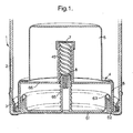
- a self-heating container comprises a can 1 having a body 2, a base 3 and an insert 4.
- the insert 4 defines a reaction chamber 5 for a primary fuel and a reservoir 6 for a fluid constituent.
- the reservoir 6 is adapted to accommodate a reduction in volume on actuation of the can 1 by a user.
- the floor 61 of the reservoir 6 is designed to move axially upon actuation of the can 1 by a user, thereby reducing the volume of the reservoir 6.
- the insert 4 is fixed relative to the body of the can 2 and the floor 61 of the reservoir is rigidly coupled to the base 3.
- the floor 61 of the reservoir 6 and the insert 4 have a co-operating screw thread arrangement 45, 65 to effect axial movement of the floor 61 relative to the insert 4.
- the periphery 62 of the floor 61 is fixed to the base 3. Adjacent to the periphery 62, a flexible diaphragm 63 is provided, to accommodate the axial movement of the floor 61, whilst the overall length of the can 1 remains fixed.
- the user of the can 1 twists the base 3 relative to the body 2, the floor screw thread 65 and the insert screw thread 45 interact to drive the floor 61 of the reservoir axially by the progression of the reservoir thread 65 along the insert thread 45.
- This axial movement is accommodated by the flexible diaphragm 63, which unfolds as the floor 61 moves.
- the movement of the floor 61 reduces the volume of the reservoir 6 and forces the fluid constituent (not shown) held therein along a flow path (not shown) from the reservoir to the reaction, chamber through the reservoir thread 65 and insert thread 45.
- the valve prevents accidental actuation of the can.
- the volume of the reservoir 6 reduces as described above, pressurising the fluid constituent held therein, and driving it through the flow path.
- the valve 7 opens in response to the increased pressure and allows the fluid constituent to enter the reaction chamber 5.
- the temperature control means comprises a "stop" 8, which expands in response to the temperature of the can 1.
- the stop 8 In “normal” conditions the stop 8 is designed to exhibit no or limited expansion and the co-operating screw threads 45, 65 progress relative to one another until the volume of the reservoir 6 is reduced to substantially 0 (i.e. when the floor 61 of the reservoir contacts the opposite boundary 66 of the reservoir 6). In this condition, the total volume of fluid constituent held in the reservoir 6 is transferred to the reaction chamber 5.
- the "stop” expands and limits the progression of the threads 45 and 65 relative to one another. This in turn halts the axial movement of the floor 61 and thereby the volume reduction of the reservoir 6. Thus, in this condition, a certain volume of fluid constituent is retained in the reservoir 6 and only the remainder is transferred to the reaction chamber 5. Thus, the reaction is halted once the "stop” acts to limit the rotation of the base 3 relative to the body 2.
- the "stop" is provided by a wax or grease held in a piston cylinder. As the ambient temperature of the surroundings rises, the wax or grease expands, driving the piston outwardly of the cylinder. The piston acts as a mechanical stop to prevent further movement of the floor 61 of the reservoir.
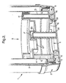
- the can 1 also includes an auxiliary reservoir 9.
- the auxiliary reservoir 9 is connected to the fluid reservoir 6 by a plurality of bypass flow paths 91.
- a meltable wax plug (not shown) is provided in each flow path 91.
- the base of the can 3 is provided with a base screw thread 35, which rotates with the base 3.
- a moveable divider 61' separates the reaction chamber 5 from the reservoir 6 and is provided with a screw thread arrangement 65, arranged to co-operate with the base screw thread 35.
- the divider 61' is prevented from rotating with the base 3 by location rods 10.
- a user of the can 1 rotates the base 3, thereby rotating the base screw thread 35.
- the divider is prevented from rotating with the base 3 by the location rods 10.
- rotation of the base 3 causes axial movement of the divider 61.
- the base screw thread 35 and location rods 10 break the frangible connection of the "break-outs" 7', opening the fluid communication between the reservoir 6 and the reaction chamber 5, Furthermore, as the divider 61 moves axially, the volume of the reservoir 5 is reduced, driving the fluid constituent out of the reservoir 5. In "normal" design conditions, all the fluid constituent is transferred to the reaction chamber 5.
- the plugs in the auxiliary flow paths 91 progressively melt and a proportion of the fluid constituent is bypassed to the auxiliary reservoir 9 and takes no part in the chemical reaction. In this way, the chemical reaction produces less heat, which prevents overheating of the product in the can 1.
- the can 1, shown in Figure 2 also has an arrangement of plates 15, 16, which are designed to accommodate restricted rotational movement.
- the plates 15, 16 are used during the insertion of the plugs and also during transport of the can, when it may encounter temperature condition that are different to those in which the can will be used.
- the plugs are formed by filling the auxiliary flow paths 91 with molten material, which is then allowed to set within the flow paths 91.
- One of the plates 15, 16 is rotated to block one end of the auxiliary flow paths 91 and the molten material is then injected into the other, open end of the flow path 91.
- the other plate 15, 16 is rotated to cover the other end of the auxiliary flow paths 91.
- the initial rotation of the base 3 will move the plates 15, 16 away from the auxiliary flow paths 91 and, depending on the ambient temperature of the container, one or more of the plugs will have melted and be forced into the auxiliary reservoir by the fluid constituent.
- One of the reagents may be a fluid or alternatively, the reagents may be provided in an inert solid form and the fluid constituent may take the form of a solvent, which initiates the chemical reaction by holding one or more of the reagents in solution.
Landscapes
- Engineering & Computer Science (AREA)
- Food Science & Technology (AREA)
- Life Sciences & Earth Sciences (AREA)
- Mechanical Engineering (AREA)
- Chemical & Material Sciences (AREA)
- Chemical Kinetics & Catalysis (AREA)
- Physical Or Chemical Processes And Apparatus (AREA)
- Packages (AREA)
- Thermotherapy And Cooling Therapy Devices (AREA)
- Cookers (AREA)
- Transition And Organic Metals Composition Catalysts For Addition Polymerization (AREA)
- Secondary Cells (AREA)
Abstract
Description
- The present invention relates to self-heating and self-cooling containers, which rely on an exothermic or endothermic chemical reaction respectively, to effect heating or cooling of a product held therein. In particular the invention proposes an arrangement to control the degree of heating or cooling produced by the chemical reaction in response to the ambient temperature of the container.
- When the ambient temperature is higher a self-heating can will be required to produce less heat to raise the temperature of the product in the can to a desired temperature. If the exothermic reaction is not controlled, the container may become uncomfortable or dangerous to handle.
- Conversely, when the ambient temperature is higher, a self-cooling can will be required to produce a greater cooling effect. Thus, the endothermic reaction will be required to absorb more heat.
- Various methods of controlling the heat produced by a self-heating pack in response to the ambient temperature have been suggested in the prior art. For example,
US 5,984,953 describes the use of a "stiffenable gel" to alter the rate of an exothermic chemical reaction, in conjunction with a vaporisable solvent which adjusts the stiffness of the gel, depending upon the ambient temperature conditions in which the "heating pack" is used. Another self-heating and self-cooling container is known fromUS 4 773 389 . - The present invention defined by the features of claim 1, requires the chemical reaction to include at least one fluid constituent, either as a reagent or solvent. A temperature control arrangement, which is driven by the ambient temperature of the container, acts to control the volume of this fluid constituent added to the reaction. The fluid constituent may include substances such as gels, provided they are sufficiently mobile and able to flow.
- Accordingly, the present invention provides a self-heating or self-cooling container which uses an exothermic or endothermic chemical reaction to effect heating or cooling, the container comprising a body for holding a product, a reaction chamber, for holding a primary fuel, a reservoir for holding a fluid constituent, and an activation means for creating a fluid flow path from the reservoir into the reaction chamber, characterised in that, the container further comprises a temperature control means, which responds to the ambient temperature of the container to control the volume of the fluid constituent entering the reaction chamber.
- Preferably the self-heating or self-cooling container includes a reservoir (for holding the fluid constituent), whose volume may be reduced by a user of the container. As the volume of the reservoir is reduced, the fluid constituent is forced into the reaction chamber initiating the chemical reaction.
- Preferably the container has at least two parts, which are adapted to move relative to one another. A first part of the container is coupled to a wall of the reservoir and the volume reduction of the reservoir is achieved by movement of this first part of the container relative to the other (second) part. The movement may be achieved by a user simply by pressing on the first part of the container. However, preferably the first and second parts of the container are coupled by a co-operating screw thread arrangement. A user of the container simply rotates first part of the container relative to the other part, to cause axial movement of a wall of the reservoir, resulting in a volume reduction thereof. Such an arrangement allows controlled addition of the fluid constituent to the reaction chamber because the rate of volume change of the reservoir and hence the rate of addition on the fluid constituent, is controlled somewhat by the pitch of the screw thread.
- Advantageously, the fluid connection between the reservoir and the reaction chamber is provided by a conduit having a normally closed valve therein. The fluid constituent is normally prevented from entering the reaction chamber by the valve, particularly during storage or transport of the container. However, upon activation of the reaction by a user, the valve opens to allow the fluid constituent to enter the reaction chamber, thereby initiating the chemical reaction.
- Advantageously, the fluid constituent in the reservoir is pressurised upon activation of the container by a user and the increase in pressure opens the valve and thereby the conduit between the reservoir and the reaction chamber. Thereafter, the valve is preferably adapted to close itself, once the pressure in the reservoir is relieved. Thus, a self-closing valve (well known to those skilled in the art) may be incorporated into the conduit for this purpose.
- Alternatively, the conduit may be normally blocked by a membrane or a "break-out" (connected to the conduit by a weakened section) which has to be pierced before the fluid constituent can enter the reaction chamber.
- In a first embodiment, the temperature control means takes the form of a "stop", whose position is determined by the ambient temperature, thereby controlling the volume of fluid constituent that can be forced into the reaction chamber. The "stop" comprises a physical stop member, which is designed to resist further activation of the container. The position of the physical stop member is controlled by a temperature sensitive material. Advantageously, the temperature sensitive material changes its volume depending upon the ambient temperature of its surroundings. Thus, if the material is constrained within a tube of constant cross section, for example, the physical stop member may be supported by the material and its axial position within the reservoir controlled. The temperature sensitive material may be chosen such that it expands or contracts significantly in response to a change in the ambient temperature of the surroundings. Suitable materials include certain waxes or greases, which expand in response to increased temperature, or materials such as Hydrogels, which expand in response to a decrease in temperature. Hydrogels are particularly preferred because their volume changes linearly with temperature.
- Taking the example of a self-heating can: At increased ambient temperatures, the exothermic reaction is required to produce less heat. Therefore, the exothermic reaction needs to be stopped before all the reagents have been used up. According to the invention, this is achieved by preventing full volume reduction of the fluid reservoir, thereby halting the addition of fluid reagent to the reaction chamber. Therefore, when the ambient temperature is higher, the stop arrangement needs to be designed such that the physical stop member prevents further actuation of the can by the user.
- Where a wax or grease, which expands in response to increased temperature, is chosen as the temperature sensitive material, the physical stop member needs to be coupled to the moving wall of the reservoir in order to stop movement of the wall earlier than could be achieved at lower temperatures. If a Hydrogel, which expands in response to decreased temperature, is chosen as the temperature sensitive material, the physical stop member needs to be coupled to the stationary part of the reservoir, to allow the greatest degree of movement of the moving wall of the reservoir, when the temperature is lowest and the least amount of movement when the temperature is higher.
- The "stop" may take the form of a mechanical arrangement, which is designed to amplify the expansion of chosen materials (metal, for example) caused by the change in ambient temperature. Preferably, the "stop" is made from a material which itself undergoes significant expansion or contraction in response to the normal variation expected in the ambient temperature (i.e. 0° - 40°c). Such materials will be well known to those skilled in the art. The "stop" must both expand / contract significantly and also act as an effective stop i.e. it must also be able to resist further activation of the can by the user.
- In a second embodiment of the invention, the self-heating or self-cooling container also comprises an auxiliary reservoir, into which any fluid constituent, not required in the reaction is directed. In the case of a self-heating can, one or more conduits are provided to this auxiliary reservoir. The or each auxiliary conduit may be blocked by a plug, which melts in response to an increase in the ambient temperature. Preferably a plurality of conduits are provided, each blocked by a plug, which melts at a different temperature. Suitable chemicals for the plugs are taken from the family of paraffin waxes, which have discrete melting points. For example, Hexadecane [melting point 18°C], Palmitate (e.g Propylpalmitate [melting point 20°C]) and Myristate (e.g Benzyl Myristate [melting point 21°C]). Thus, as the ambient temperature increases one or more plugs melt, opening the associated auxiliary conduit. On actuation of the container by a user, a proportion of the fluid constituent is forced into the reaction chamber but a proportion is also forced into the auxiliary reservoir, where it takes no part in the chemical reaction.
- In this embodiment, one or more conduits may be provided between the reservoir and the auxiliary reservoir with a valve located therein which progressively opens in response to an increase in the ambient temperature of the container. However, preferably a plurality of conduits is provided to the auxiliary reservoir, each blocked by a plug, which melts at a different, predetermined temperature. As the ambient temperature increases, so does the number of plugs that melt, opening more of the conduits to the auxiliary reservoir and thereby increasing the volume of fluid directed away from the reaction chamber.
- The advantage of this arrangement is the simplicity of construction. The plugs are simply small slugs of material, which melt at a defined temperature.
- Preferably, the plug material and material used to define the auxiliary conduits (into which the plugs are placed) have a high surface tension with respect to each other, so that the plugs "cling" to the conduit and can only be removed by melting. A step may also be defined in the wall of the auxiliary conduit, to prevent the plug being forced out of its associated conduit by the pressure applied to the fluid constituent. Again, the conduits and plugs are designed such that the plug may only be removed from its associated conduit by melting.
- Finally, the fluid constituent may be provided in the form of a gel and the reservoir arrangement may be designed such that the fluid constituent itself substantially blocks the one or more auxiliary conduits. As the ambient temperature rises, the gel becomes more mobile and a greater proportion of the gel is forced through the auxiliary conduits to the auxiliary reservoir, rather than to the reaction chamber. In this arrangement the diameter and length of the or each auxiliary conduit is critical in determining the volume of fluid constituent entering the auxiliary reservoir, compared to that entering the reaction chamber.
- The present invention will now be described by way of example only with reference to the accompanying drawings in which:-
-
Fig.1 shows a side, section view of a self-heating can according to a first embodiment of the invention. In this embodiment a "stop" (whose position is determined by the ambient temperature) is arranged to limit the volume reduction of the reservoir and thereby control the volume of fluid constituent driven into the reaction chamber. -
Fig.2 shows a side, section view of a self-heating can according to a second embodiment of the invention. In this embodiment an auxiliary reservoir is provided into which a volume of the fluid constituent is diverted, depending upon the ambient temperature. - Referring to
figures 1 and2 , a self-heating container according to the invention comprises a can 1 having abody 2, a base 3 and aninsert 4. Theinsert 4 defines areaction chamber 5 for a primary fuel and areservoir 6 for a fluid constituent. Thereservoir 6 is adapted to accommodate a reduction in volume on actuation of the can 1 by a user. - Referring to
Figure 1 , thefloor 61 of thereservoir 6 is designed to move axially upon actuation of the can 1 by a user, thereby reducing the volume of thereservoir 6. Theinsert 4 is fixed relative to the body of thecan 2 and thefloor 61 of the reservoir is rigidly coupled to the base 3. Thefloor 61 of thereservoir 6 and theinsert 4 have a co-operatingscrew thread arrangement floor 61 relative to theinsert 4. Theperiphery 62 of thefloor 61 is fixed to the base 3. Adjacent to theperiphery 62, aflexible diaphragm 63 is provided, to accommodate the axial movement of thefloor 61, whilst the overall length of the can 1 remains fixed. - In use, the user of the can 1 twists the base 3 relative to the
body 2, thefloor screw thread 65 and theinsert screw thread 45 interact to drive thefloor 61 of the reservoir axially by the progression of thereservoir thread 65 along theinsert thread 45. This axial movement is accommodated by theflexible diaphragm 63, which unfolds as thefloor 61 moves. The movement of thefloor 61, reduces the volume of thereservoir 6 and forces the fluid constituent (not shown) held therein along a flow path (not shown) from the reservoir to the reaction, chamber through thereservoir thread 65 and insertthread 45. - A pressure-activated
valve 7, which is normally closed, is provided in the flow path between the reservoir and thereaction chamber 5. The valve prevents accidental actuation of the can. However, once the user rotates the base 3 of the can 1, the volume of thereservoir 6 reduces as described above, pressurising the fluid constituent held therein, and driving it through the flow path. Thevalve 7 opens in response to the increased pressure and allows the fluid constituent to enter thereaction chamber 5. - In a first embodiment of the invention (shown in
figure 1 ) the temperature control means comprises a "stop" 8, which expands in response to the temperature of the can 1. In "normal" conditions thestop 8 is designed to exhibit no or limited expansion and theco-operating screw threads reservoir 6 is reduced to substantially 0 (i.e. when thefloor 61 of the reservoir contacts theopposite boundary 66 of the reservoir 6). In this condition, the total volume of fluid constituent held in thereservoir 6 is transferred to thereaction chamber 5. - However, when the ambient temperature is higher, the "stop" expands and limits the progression of the
threads floor 61 and thereby the volume reduction of thereservoir 6. Thus, in this condition, a certain volume of fluid constituent is retained in thereservoir 6 and only the remainder is transferred to thereaction chamber 5. Thus, the reaction is halted once the "stop" acts to limit the rotation of the base 3 relative to thebody 2. - Preferably, the "stop" is provided by a wax or grease held in a piston cylinder. As the ambient temperature of the surroundings rises, the wax or grease expands, driving the piston outwardly of the cylinder. The piston acts as a mechanical stop to prevent further movement of the
floor 61 of the reservoir. - In a second embodiment of the invention (as shown in
Figure 2 ), the can 1 also includes anauxiliary reservoir 9. Theauxiliary reservoir 9 is connected to thefluid reservoir 6 by a plurality ofbypass flow paths 91. A meltable wax plug (not shown) is provided in eachflow path 91. - In "normal" conditions, the volume reduction of the
reservoir 6 occurs as previously described. All the fluid constituent is directed to the reaction chamber, because the meltable plugs remain solid and block thebypass flow paths 91. As the ambient temperature increases, some or all of the plugs melt and the associatedbypass flow paths 91 open, providing fluid communication with theauxiliary reservoir 9. In these conditions, only a portion of the fluid constituent is transferred from thereservoir 6 to thereaction chamber 5. The remaining portion is directed to theauxiliary reservoir 9, where it takes no part in the chemical reaction. - As shown in
Figure 2 , the flow path or paths between thereservoir 6 and thereaction chamber 5 are normally blocked by a "break-out" 7' prior to activation of the can by a user. It will be appreciated that thevalve 7 shown inFigure 1 may be replaced by a similar "break-out" to those shown inFigure 2 and vice versa. - In this second embodiment, the base of the can 3 is provided with a
base screw thread 35, which rotates with the base 3. A moveable divider 61' separates thereaction chamber 5 from thereservoir 6 and is provided with ascrew thread arrangement 65, arranged to co-operate with thebase screw thread 35. The divider 61' is prevented from rotating with the base 3 bylocation rods 10. - In use, a user of the can 1 rotates the base 3, thereby rotating the
base screw thread 35. The divider is prevented from rotating with the base 3 by thelocation rods 10. As thedivider 61 is unable to rotate, rotation of the base 3 causes axial movement of thedivider 61. Thebase screw thread 35 andlocation rods 10, break the frangible connection of the "break-outs" 7', opening the fluid communication between thereservoir 6 and thereaction chamber 5, Furthermore, as thedivider 61 moves axially, the volume of thereservoir 5 is reduced, driving the fluid constituent out of thereservoir 5. In "normal" design conditions, all the fluid constituent is transferred to thereaction chamber 5. As the ambient temperature rises above the "normal" design conditions, the plugs in theauxiliary flow paths 91 progressively melt and a proportion of the fluid constituent is bypassed to theauxiliary reservoir 9 and takes no part in the chemical reaction. In this way, the chemical reaction produces less heat, which prevents overheating of the product in the can 1. - The can 1, shown in
Figure 2 also has an arrangement ofplates plates - Preferable the plugs are formed by filling the
auxiliary flow paths 91 with molten material, which is then allowed to set within theflow paths 91. One of theplates auxiliary flow paths 91 and the molten material is then injected into the other, open end of theflow path 91. When full, theother plate auxiliary flow paths 91. Thus, if the can 1 is subjected to higher temperatures during transport, the plugs may melt but will be constrained within theflow paths 91 and will re-set if the temperature reduces. Upon first activation of the can by a user, the initial rotation of the base 3 will move theplates auxiliary flow paths 91 and, depending on the ambient temperature of the container, one or more of the plugs will have melted and be forced into the auxiliary reservoir by the fluid constituent. - It will be apparent that certain of the features of the can shown in
Figure 2 may be applied to the can shown inFigure 1 and vice versa. Furthermore, many other methods of sealing the fluid connection between the reaction chamber and the reservoir will be apparent to those skilled in the art. For example, it is not beyond the scope of the invention to provide a flexible reservoir for the fluid constituent (such as a flexible pouch), which is pierced upon first actuation of the can by the user, to allow the fluid constituent access to the primary fuel in the reaction chamber. - Suitable exothermic and endothermic chemical reactions will also be apparent to those skilled in the art. One of the reagents may be a fluid or alternatively, the reagents may be provided in an inert solid form and the fluid constituent may take the form of a solvent, which initiates the chemical reaction by holding one or more of the reagents in solution.
Claims (12)
- A self-heating or self-cooling container (1) which uses an exothermic or endothermic chemical reaction to effect heating or cooling, the container comprising- a body (2) for holding a product- a reaction chamber (5), for holding a primary fuel,- a reservoir (6), for holding a fluid constituent, and- an activation means (7,7') for creating a fluid flow path from the reservoir into the reaction chamber,characterised in that,
the container (1) further comprises a temperature control means (8,91), which responds to the ambient temperature of the container to control the volume of the fluid constituent entering the reaction chamber (5). - A self-heating or self-cooling container according to Claim 1, wherein the reservoir (6) is adapted to accommodate a reduction in volume, the volume reduction pressurising the fluid constituent and thereby creating the fluid flow path into the reaction chamber (5).
- A self-heating or self-cooling container according to claim 2, wherein the reservoir (6) comprises two portions, a housing portion and a plunger portion (61) and the plunger portion (61) is adapted to move within the housing portion to produce the volume reduction of the reservoir.
- A self-heating or self-cooling container according to Claim 3, wherein the plunger portion (61) is provided with a screw thread arrangement (65) which co-operates with a complimentary screw thread arrangement on the housing portion (45,35) to effect movement of the plunger portion (61) within the housing portion.
- A self-heating or self-cooling container according to any of Claims 3 to 4, wherein the plunger portion (61) is anchored to the container (1) and movement of the plunger portion (61) is accommodated by a flexible diaphragm (63).
- A self-heating or self cooling container according to any of the preceding claims, having a fluid flow path between the reservoir and the reaction chamber, wherein a valve (7) is provided in the fluid flow path (7) and the valve is adapted to open in response to increased pressure within the reservoir.
- A self-heating container according to any one of Claims 2 to 6, wherein the temperature control means comprises a stop (8), whose position automatically adjusts in response to the ambient temperature of the container, the stop (8) arranged to prevent further volume reduction of the reservoir and thereby to prevent further addition of the fluid constituent to the reaction chamber (5).
- A self-heating container according to claim 7, wherein the temperature control means comprises a material, which expands significantly in response to an increase in the ambient temperature of the container.
- A self-heating container according to Claim 8, wherein the material is a wax or oil.
- A self-heating or self-cooling container according to Claim 7, wherein the temperature control means comprises a mechanical arrangement, which expands significantly in response to an increase in the ambient temperature of the surroundings.
- A self-heating container according to any one of Claims 2 to 6, further comprising:- an auxiliary reservoir (9) connected to the reservoir (5), by one or more flow paths (91)- wherein the temperature control means comprises a plug associated with the or each flow path (91), which is adapted to open when the ambient temperature of the surroundings reaches a pre-defined temperature.
- A self-heating container according to Claim 11, wherein the or each plug is made from a material, which melts in response to an increase in the ambient temperature of the container.
Priority Applications (1)
| Application Number | Priority Date | Filing Date | Title |
|---|---|---|---|
| EP03730018A EP1505896B1 (en) | 2002-05-17 | 2003-05-13 | Self heating or cooling container |
Applications Claiming Priority (4)
| Application Number | Priority Date | Filing Date | Title |
|---|---|---|---|
| EP02253508A EP1362537A1 (en) | 2002-05-17 | 2002-05-17 | Self heating or cooling container |
| EP02253508 | 2002-05-17 | ||
| EP03730018A EP1505896B1 (en) | 2002-05-17 | 2003-05-13 | Self heating or cooling container |
| PCT/EP2003/004981 WO2003096855A2 (en) | 2002-05-17 | 2003-05-13 | Self heating or cooling container |
Publications (2)
| Publication Number | Publication Date |
|---|---|
| EP1505896A2 EP1505896A2 (en) | 2005-02-16 |
| EP1505896B1 true EP1505896B1 (en) | 2008-06-04 |
Family
ID=29266012
Family Applications (2)
| Application Number | Title | Priority Date | Filing Date |
|---|---|---|---|
| EP02253508A Withdrawn EP1362537A1 (en) | 2002-05-17 | 2002-05-17 | Self heating or cooling container |
| EP03730018A Expired - Lifetime EP1505896B1 (en) | 2002-05-17 | 2003-05-13 | Self heating or cooling container |
Family Applications Before (1)
| Application Number | Title | Priority Date | Filing Date |
|---|---|---|---|
| EP02253508A Withdrawn EP1362537A1 (en) | 2002-05-17 | 2002-05-17 | Self heating or cooling container |
Country Status (9)
| Country | Link |
|---|---|
| US (1) | US7350361B2 (en) |
| EP (2) | EP1362537A1 (en) |
| JP (1) | JP4373325B2 (en) |
| AT (1) | ATE397401T1 (en) |
| AU (1) | AU2003240629A1 (en) |
| DE (1) | DE60321461D1 (en) |
| ES (1) | ES2307939T3 (en) |
| WO (1) | WO2003096855A2 (en) |
| ZA (1) | ZA200408949B (en) |
Families Citing this family (19)
| Publication number | Priority date | Publication date | Assignee | Title |
|---|---|---|---|---|
| USRE47895E1 (en) | 1999-03-08 | 2020-03-03 | Ipcom Gmbh & Co. Kg | Method of allocating access rights to a telecommunications channel to subscriber stations of a telecommunications network and subscriber station |
| GB0411919D0 (en) * | 2004-05-27 | 2004-06-30 | Huhtamaki Uk Ltd | Active container |
| GB0508696D0 (en) * | 2005-04-29 | 2005-06-08 | Uniq Prepared Foods | Containers for selectably changing the temprature of a stored material by mixing two reactants |
| WO2007059151A2 (en) | 2005-11-14 | 2007-05-24 | Heat Wave Technologies Llc | Improved self-heating container |
| BRPI0809438A2 (en) * | 2007-03-27 | 2015-06-16 | Cryovac Inc | Package to make juicy meat on demand |
| US8556108B2 (en) * | 2007-09-26 | 2013-10-15 | Heat Wave Technologies, Llc | Self-heating systems and methods for rapidly heating a comestible substance |
| US7993692B2 (en) * | 2008-09-10 | 2011-08-09 | Cryovac, Inc. | Package assembly for on-demand marination and method for providing the same |
| US8608696B1 (en) | 2009-02-24 | 2013-12-17 | North Carolina State University | Rapid fluid cooling devices and methods for cooling fluids |
| US8578926B2 (en) * | 2009-03-09 | 2013-11-12 | Heat Wave Technologies, Llc | Self-heating systems and methods for rapidly heating a comestible substance |
| US8360048B2 (en) | 2009-03-09 | 2013-01-29 | Heat Wave Technologies, Llc | Self-heating systems and methods for rapidly heating a comestible substance |
| US9016511B2 (en) | 2010-07-19 | 2015-04-28 | Silgan Containers Llc | Heated container |
| US9039924B2 (en) | 2010-12-02 | 2015-05-26 | Frosty Cold, Llc | Cooling agent for cold packs and food and beverage containers |
| US9879897B2 (en) | 2010-12-02 | 2018-01-30 | Frosty Cold, Llc | Cooling agent for cold packs and food and beverage containers |
| US10155698B2 (en) | 2010-12-02 | 2018-12-18 | Frosty Cold, Llc | Cooling agent for cold packs and food and beverage containers |
| US20120193367A1 (en) | 2011-01-27 | 2012-08-02 | Silgan Containers Llc | Heated container having chemical heating mechanism |
| GB201114285D0 (en) * | 2011-08-19 | 2011-10-05 | Genergy Technology Ltd | A heating device |
| EP2918146A1 (en) * | 2012-11-06 | 2015-09-16 | Heatgenie, Inc. | Heating devices and methods with auto-shutdown |
| CN109255264A (en) * | 2018-09-12 | 2019-01-22 | 苏州三拓冷链技术有限公司 | A kind of phase transformation thermal drivers realization Boolean logic method and apparatus |
| CN116873389B (en) * | 2023-06-30 | 2026-04-03 | 浙江大学中原研究院 | Controllable injection self-heating device and self-heating container |
Family Cites Families (9)
| Publication number | Priority date | Publication date | Assignee | Title |
|---|---|---|---|---|
| US1833105A (en) * | 1928-10-26 | 1931-11-24 | Louis V Aronson | Massage device |
| US4773389A (en) * | 1986-02-19 | 1988-09-27 | Chori Company, Ltd. | Self-heating foodstuff container |
| US4784678A (en) * | 1987-04-06 | 1988-11-15 | The Coca-Cola Company | Self-cooling container |
| US5257755A (en) * | 1991-11-18 | 1993-11-02 | Hughes Aircraft Company | Endothermic cooler for electronic components |
| US5313799A (en) * | 1992-11-06 | 1994-05-24 | Israel Siegel | Magnetic ice cube |
| US6103280A (en) * | 1997-09-20 | 2000-08-15 | Bass Public Limited Company | Self-cooling containers of beverage and foodstuffs |
| US5984953A (en) | 1998-05-21 | 1999-11-16 | Tempra Technology, Inc. | Self-regulating heat pack |
| US6178753B1 (en) * | 1999-04-19 | 2001-01-30 | Ontro, Inc. | Container with self-heating module having liquid reactant and breakable reactant barrier at distal end of module |
| DE10003534A1 (en) * | 2000-01-27 | 2001-08-16 | Ebbecke Reinhard | Disposable containers for heating and cooling liquids |
-
2002
- 2002-05-17 EP EP02253508A patent/EP1362537A1/en not_active Withdrawn
-
2003
- 2003-05-13 EP EP03730018A patent/EP1505896B1/en not_active Expired - Lifetime
- 2003-05-13 JP JP2004504863A patent/JP4373325B2/en not_active Expired - Fee Related
- 2003-05-13 DE DE60321461T patent/DE60321461D1/en not_active Expired - Lifetime
- 2003-05-13 WO PCT/EP2003/004981 patent/WO2003096855A2/en not_active Ceased
- 2003-05-13 AT AT03730018T patent/ATE397401T1/en not_active IP Right Cessation
- 2003-05-13 US US10/514,684 patent/US7350361B2/en not_active Expired - Lifetime
- 2003-05-13 AU AU2003240629A patent/AU2003240629A1/en not_active Abandoned
- 2003-05-13 ES ES03730018T patent/ES2307939T3/en not_active Expired - Lifetime
-
2004
- 2004-11-04 ZA ZA2004/08949A patent/ZA200408949B/en unknown
Also Published As
| Publication number | Publication date |
|---|---|
| WO2003096855A8 (en) | 2004-12-16 |
| AU2003240629A1 (en) | 2003-12-02 |
| DE60321461D1 (en) | 2008-07-17 |
| JP4373325B2 (en) | 2009-11-25 |
| ES2307939T3 (en) | 2008-12-01 |
| ATE397401T1 (en) | 2008-06-15 |
| JP2006507852A (en) | 2006-03-09 |
| US20050155599A1 (en) | 2005-07-21 |
| EP1505896A2 (en) | 2005-02-16 |
| ZA200408949B (en) | 2005-12-28 |
| US7350361B2 (en) | 2008-04-01 |
| WO2003096855A2 (en) | 2003-11-27 |
| WO2003096855A3 (en) | 2004-02-05 |
| EP1362537A1 (en) | 2003-11-19 |
Similar Documents
| Publication | Publication Date | Title |
|---|---|---|
| US7350361B2 (en) | Self-heating or cooling container | |
| JP2764110B2 (en) | Fail-safe thermostat for vehicle cooling system | |
| KR102778273B1 (en) | Temperature pressure relief device | |
| US5155298A (en) | Thermally activated case venting safety apparatus | |
| JP3354951B2 (en) | Cylinder piston device | |
| KR20090042805A (en) | Bypass valve for chiller connected downstream of hydraulic system | |
| DK2177783T3 (en) | Gas spring safety device | |
| US5749439A (en) | Hydraulic fluid storage for a powertrain | |
| CA2119009A1 (en) | Reusable heat releasing pack | |
| EP2951414B1 (en) | Hydro-actuated thermostats | |
| AU2007319319A1 (en) | Downhole trigger device having extrudable time delay material | |
| JPH08277951A (en) | Valve | |
| EP1764809A1 (en) | A protection element for a capacitor with self-healing properties | |
| US10858171B2 (en) | Portable heating for small quantities of consumer product | |
| US4353500A (en) | Thermostat | |
| US5577740A (en) | Thermal activated self-releasing seal for boiler | |
| BRPI0915452B1 (en) | lock with thermal safety function for a hydrodynamic machine | |
| WO2001028394A1 (en) | Self-heating or self-cooling containers | |
| EP3786485B1 (en) | Temperature regulating valve and thermal management system provided with temperature regulating valve | |
| EP4238614B1 (en) | Safety system for vehicle propulsion battery pack | |
| WO2023166397A1 (en) | Safety system for vehicle propulsion battery pack | |
| US6220838B1 (en) | Progressive cavity pump with meltable stator | |
| RU22697U1 (en) | THERMAL VALVE | |
| US20060252973A1 (en) | Liquid mercury containing device and method for reducing toxicity of liquid mercury in liquid mercury containing device | |
| JPS64572B2 (en) |
Legal Events
| Date | Code | Title | Description |
|---|---|---|---|
| PUAI | Public reference made under article 153(3) epc to a published international application that has entered the european phase |
Free format text: ORIGINAL CODE: 0009012 |
|
| 17P | Request for examination filed |
Effective date: 20041018 |
|
| AK | Designated contracting states |
Kind code of ref document: A2 Designated state(s): AT BE BG CH CY CZ DE DK EE ES FI FR GB GR HU IE IT LI LU MC NL PT RO SE SI SK TR |
|
| AX | Request for extension of the european patent |
Extension state: AL LT LV MK |
|
| DAX | Request for extension of the european patent (deleted) | ||
| GRAP | Despatch of communication of intention to grant a patent |
Free format text: ORIGINAL CODE: EPIDOSNIGR1 |
|
| GRAS | Grant fee paid |
Free format text: ORIGINAL CODE: EPIDOSNIGR3 |
|
| GRAA | (expected) grant |
Free format text: ORIGINAL CODE: 0009210 |
|
| AK | Designated contracting states |
Kind code of ref document: B1 Designated state(s): AT BE BG CH CY CZ DE DK EE ES FI FR GB GR HU IE IT LI LU MC NL PT RO SE SI SK TR |
|
| REG | Reference to a national code |
Ref country code: GB Ref legal event code: FG4D |
|
| REG | Reference to a national code |
Ref country code: CH Ref legal event code: EP |
|
| REF | Corresponds to: |
Ref document number: 60321461 Country of ref document: DE Date of ref document: 20080717 Kind code of ref document: P |
|
| REG | Reference to a national code |
Ref country code: IE Ref legal event code: FG4D |
|
| PG25 | Lapsed in a contracting state [announced via postgrant information from national office to epo] |
Ref country code: FI Free format text: LAPSE BECAUSE OF FAILURE TO SUBMIT A TRANSLATION OF THE DESCRIPTION OR TO PAY THE FEE WITHIN THE PRESCRIBED TIME-LIMIT Effective date: 20080604 Ref country code: SI Free format text: LAPSE BECAUSE OF FAILURE TO SUBMIT A TRANSLATION OF THE DESCRIPTION OR TO PAY THE FEE WITHIN THE PRESCRIBED TIME-LIMIT Effective date: 20080604 |
|
| PG25 | Lapsed in a contracting state [announced via postgrant information from national office to epo] |
Ref country code: AT Free format text: LAPSE BECAUSE OF FAILURE TO SUBMIT A TRANSLATION OF THE DESCRIPTION OR TO PAY THE FEE WITHIN THE PRESCRIBED TIME-LIMIT Effective date: 20080604 Ref country code: NL Free format text: LAPSE BECAUSE OF FAILURE TO SUBMIT A TRANSLATION OF THE DESCRIPTION OR TO PAY THE FEE WITHIN THE PRESCRIBED TIME-LIMIT Effective date: 20080604 |
|
| NLV1 | Nl: lapsed or annulled due to failure to fulfill the requirements of art. 29p and 29m of the patents act | ||
| REG | Reference to a national code |
Ref country code: ES Ref legal event code: FG2A Ref document number: 2307939 Country of ref document: ES Kind code of ref document: T3 |
|
| PG25 | Lapsed in a contracting state [announced via postgrant information from national office to epo] |
Ref country code: SE Free format text: LAPSE BECAUSE OF FAILURE TO SUBMIT A TRANSLATION OF THE DESCRIPTION OR TO PAY THE FEE WITHIN THE PRESCRIBED TIME-LIMIT Effective date: 20080904 Ref country code: CZ Free format text: LAPSE BECAUSE OF FAILURE TO SUBMIT A TRANSLATION OF THE DESCRIPTION OR TO PAY THE FEE WITHIN THE PRESCRIBED TIME-LIMIT Effective date: 20080604 Ref country code: PT Free format text: LAPSE BECAUSE OF FAILURE TO SUBMIT A TRANSLATION OF THE DESCRIPTION OR TO PAY THE FEE WITHIN THE PRESCRIBED TIME-LIMIT Effective date: 20081104 |
|
| PG25 | Lapsed in a contracting state [announced via postgrant information from national office to epo] |
Ref country code: SK Free format text: LAPSE BECAUSE OF FAILURE TO SUBMIT A TRANSLATION OF THE DESCRIPTION OR TO PAY THE FEE WITHIN THE PRESCRIBED TIME-LIMIT Effective date: 20080604 Ref country code: RO Free format text: LAPSE BECAUSE OF FAILURE TO SUBMIT A TRANSLATION OF THE DESCRIPTION OR TO PAY THE FEE WITHIN THE PRESCRIBED TIME-LIMIT Effective date: 20080604 Ref country code: BE Free format text: LAPSE BECAUSE OF FAILURE TO SUBMIT A TRANSLATION OF THE DESCRIPTION OR TO PAY THE FEE WITHIN THE PRESCRIBED TIME-LIMIT Effective date: 20080604 |
|
| PLBE | No opposition filed within time limit |
Free format text: ORIGINAL CODE: 0009261 |
|
| STAA | Information on the status of an ep patent application or granted ep patent |
Free format text: STATUS: NO OPPOSITION FILED WITHIN TIME LIMIT |
|
| PG25 | Lapsed in a contracting state [announced via postgrant information from national office to epo] |
Ref country code: BG Free format text: LAPSE BECAUSE OF FAILURE TO SUBMIT A TRANSLATION OF THE DESCRIPTION OR TO PAY THE FEE WITHIN THE PRESCRIBED TIME-LIMIT Effective date: 20080904 Ref country code: DK Free format text: LAPSE BECAUSE OF FAILURE TO SUBMIT A TRANSLATION OF THE DESCRIPTION OR TO PAY THE FEE WITHIN THE PRESCRIBED TIME-LIMIT Effective date: 20080604 Ref country code: EE Free format text: LAPSE BECAUSE OF FAILURE TO SUBMIT A TRANSLATION OF THE DESCRIPTION OR TO PAY THE FEE WITHIN THE PRESCRIBED TIME-LIMIT Effective date: 20080604 |
|
| 26N | No opposition filed |
Effective date: 20090305 |
|
| PG25 | Lapsed in a contracting state [announced via postgrant information from national office to epo] |
Ref country code: MC Free format text: LAPSE BECAUSE OF NON-PAYMENT OF DUE FEES Effective date: 20090531 |
|
| REG | Reference to a national code |
Ref country code: CH Ref legal event code: PL |
|
| PG25 | Lapsed in a contracting state [announced via postgrant information from national office to epo] |
Ref country code: LI Free format text: LAPSE BECAUSE OF NON-PAYMENT OF DUE FEES Effective date: 20090531 Ref country code: CH Free format text: LAPSE BECAUSE OF NON-PAYMENT OF DUE FEES Effective date: 20090531 |
|
| REG | Reference to a national code |
Ref country code: IE Ref legal event code: MM4A |
|
| PG25 | Lapsed in a contracting state [announced via postgrant information from national office to epo] |
Ref country code: IE Free format text: LAPSE BECAUSE OF NON-PAYMENT OF DUE FEES Effective date: 20090513 |
|
| PG25 | Lapsed in a contracting state [announced via postgrant information from national office to epo] |
Ref country code: GR Free format text: LAPSE BECAUSE OF FAILURE TO SUBMIT A TRANSLATION OF THE DESCRIPTION OR TO PAY THE FEE WITHIN THE PRESCRIBED TIME-LIMIT Effective date: 20080905 |
|
| PG25 | Lapsed in a contracting state [announced via postgrant information from national office to epo] |
Ref country code: LU Free format text: LAPSE BECAUSE OF NON-PAYMENT OF DUE FEES Effective date: 20090513 |
|
| PG25 | Lapsed in a contracting state [announced via postgrant information from national office to epo] |
Ref country code: HU Free format text: LAPSE BECAUSE OF FAILURE TO SUBMIT A TRANSLATION OF THE DESCRIPTION OR TO PAY THE FEE WITHIN THE PRESCRIBED TIME-LIMIT Effective date: 20081205 |
|
| PG25 | Lapsed in a contracting state [announced via postgrant information from national office to epo] |
Ref country code: TR Free format text: LAPSE BECAUSE OF FAILURE TO SUBMIT A TRANSLATION OF THE DESCRIPTION OR TO PAY THE FEE WITHIN THE PRESCRIBED TIME-LIMIT Effective date: 20080604 |
|
| PG25 | Lapsed in a contracting state [announced via postgrant information from national office to epo] |
Ref country code: CY Free format text: LAPSE BECAUSE OF FAILURE TO SUBMIT A TRANSLATION OF THE DESCRIPTION OR TO PAY THE FEE WITHIN THE PRESCRIBED TIME-LIMIT Effective date: 20080604 |
|
| REG | Reference to a national code |
Ref country code: DE Ref legal event code: R082 Ref document number: 60321461 Country of ref document: DE Representative=s name: RAINER CALLIES, DE Ref country code: DE Ref legal event code: R082 Ref document number: 60321461 Country of ref document: DE Representative=s name: CALLIES, RAINER, DIPL.-PHYS. DR.RER.NAT., DE |
|
| REG | Reference to a national code |
Ref country code: FR Ref legal event code: PLFP Year of fee payment: 14 |
|
| PGFP | Annual fee paid to national office [announced via postgrant information from national office to epo] |
Ref country code: GB Payment date: 20160520 Year of fee payment: 14 Ref country code: DE Payment date: 20160520 Year of fee payment: 14 Ref country code: ES Payment date: 20160512 Year of fee payment: 14 |
|
| PGFP | Annual fee paid to national office [announced via postgrant information from national office to epo] |
Ref country code: IT Payment date: 20160525 Year of fee payment: 14 Ref country code: FR Payment date: 20160520 Year of fee payment: 14 |
|
| REG | Reference to a national code |
Ref country code: DE Ref legal event code: R119 Ref document number: 60321461 Country of ref document: DE |
|
| GBPC | Gb: european patent ceased through non-payment of renewal fee |
Effective date: 20170513 |
|
| REG | Reference to a national code |
Ref country code: FR Ref legal event code: ST Effective date: 20180131 |
|
| PG25 | Lapsed in a contracting state [announced via postgrant information from national office to epo] |
Ref country code: GB Free format text: LAPSE BECAUSE OF NON-PAYMENT OF DUE FEES Effective date: 20170513 Ref country code: DE Free format text: LAPSE BECAUSE OF NON-PAYMENT OF DUE FEES Effective date: 20171201 |
|
| PG25 | Lapsed in a contracting state [announced via postgrant information from national office to epo] |
Ref country code: FR Free format text: LAPSE BECAUSE OF NON-PAYMENT OF DUE FEES Effective date: 20170531 Ref country code: IT Free format text: LAPSE BECAUSE OF NON-PAYMENT OF DUE FEES Effective date: 20170513 |
|
| REG | Reference to a national code |
Ref country code: ES Ref legal event code: FD2A Effective date: 20180705 |
|
| PG25 | Lapsed in a contracting state [announced via postgrant information from national office to epo] |
Ref country code: ES Free format text: LAPSE BECAUSE OF NON-PAYMENT OF DUE FEES Effective date: 20170514 |