EP1505851A1 - Supporting device for sound generator - Google Patents
Supporting device for sound generator Download PDFInfo
- Publication number
- EP1505851A1 EP1505851A1 EP03017536A EP03017536A EP1505851A1 EP 1505851 A1 EP1505851 A1 EP 1505851A1 EP 03017536 A EP03017536 A EP 03017536A EP 03017536 A EP03017536 A EP 03017536A EP 1505851 A1 EP1505851 A1 EP 1505851A1
- Authority
- EP
- European Patent Office
- Prior art keywords
- bracket
- housing
- sound generator
- guiding element
- fixing
- Prior art date
- Legal status (The legal status is an assumption and is not a legal conclusion. Google has not performed a legal analysis and makes no representation as to the accuracy of the status listed.)
- Granted
Links
Images




Classifications
-
- H—ELECTRICITY
- H04—ELECTRIC COMMUNICATION TECHNIQUE
- H04R—LOUDSPEAKERS, MICROPHONES, GRAMOPHONE PICK-UPS OR LIKE ACOUSTIC ELECTROMECHANICAL TRANSDUCERS; ELECTRIC HEARING AIDS; PUBLIC ADDRESS SYSTEMS
- H04R1/00—Details of transducers, loudspeakers or microphones
- H04R1/02—Casings; Cabinets ; Supports therefor; Mountings therein
- H04R1/025—Arrangements for fixing loudspeaker transducers, e.g. in a box, furniture
-
- H—ELECTRICITY
- H04—ELECTRIC COMMUNICATION TECHNIQUE
- H04R—LOUDSPEAKERS, MICROPHONES, GRAMOPHONE PICK-UPS OR LIKE ACOUSTIC ELECTROMECHANICAL TRANSDUCERS; ELECTRIC HEARING AIDS; PUBLIC ADDRESS SYSTEMS
- H04R2499/00—Aspects covered by H04R or H04S not otherwise provided for in their subgroups
- H04R2499/10—General applications
- H04R2499/15—Transducers incorporated in visual displaying devices, e.g. televisions, computer displays, laptops
Definitions
- the present invention relates to the fastening of sound generators in housings of television sets and/or PC (personal computer) monitors, and in particular to a supporting device for a loudspeaker to be attached to a housing and a method for supporting the sound generator in the housing.
- PC personal computer
- a sound generator for generating audible sound and a display device or image generating device e.g. a cathode ray tube (CRT), a flat screen or a monitor, are arranged in a housing adjacent to each other such that a sound signal accompanies the video or image signal.
- a display device or image generating device e.g. a cathode ray tube (CRT), a flat screen or a monitor
- the generation of sound using a sound generator is associated with a generation of mechanical vibrations being transferred to the housing, in which the sound generator is arranged.
- Especially mechanical vibrations in the audio range caused by sound generated by the sound generator involve adverse effects on an image generated by an image generating device included in the housing.
- the main disadvantage of such arrangements is the fact that an acoustic coupling between the sound generator, i.e. the loudspeaker, and a shadow mask of the monitor or the image generating device occurs.
- CTR color cathode ray tubes
- the spots emit light when illuminated by the electron beams due to phosphorescence.
- Each picture element pixel emits light when it is illuminated and thus a color is seen in the light being emitted from a signal pixel whereby the color of the emitted light is determined by the intensity of the three individual electron beams illuminating the color triads in the picture element.
- a complete color image is formed on the screen of the color cathode ray tube being covered by colored light emitting pixels by scanning the three electron beams horizontally and vertically by predetermined amounts.
- the composition of the beam intensities corresponds to the color to be emitted from the picture element being illuminated.
- a metallic mesh i.e. a shadow mask is arranged in front of the interior surface of the screen of a color cathode ray tube (CRT).
- CRT color cathode ray tube
- the metallic mesh is provided in order to avoid any illumination of adjacent triads.
- the metallic mesh has such a structure that only one of the three electron beams is allowed to pass through one hole and to cause an illumination of one triad.
- a monitor which has a tubular loudspeaker reducing mask vibrations of a cathode ray tube arranged adjacent to the loudspeaker system.
- the loudspeaker system is physically integrated with a monitor and comprises an electro-acoustic transducer, a passive radiator and a tube mounted in between them.
- the tube has a circular cross section and its axis is parallel to the plane of the metallic mesh, i.e. the shadow mask, of the cathode ray tube.
- a tubular housing or enclosure of the transducer includes a hollow elongated cylinder which is mechanical very rigid in the radial direction, thus that radial oscillations/vibrations hardly occur.
- the tubular housing is mounted in such a way, that its axis is substantially in parallel with a plane of a front panel of the monitor.
- the shadow mask (metallic mesh) of the cathode ray tube is mainly sensitive to vibrations in its plane an arrangement of the tubular housing such that its axis is essentially in parallel to the mask reduces a mechanical coupling between the loudspeaker and the shadow mask of the cathode ray tube.
- the tubular housing can be elastically attached to an interior or exterior of the monitor system.
- a disadvantage of the arrangement of WO 98/41014 is that the tubes are fixed to the housing such that still an acoustic coupling between the sound generator and the image generating device is possible resulting in a degraded image quality in many circumstances.
- Fig. 6 shows a supporting device for supporting a sound generator 100 in a housing 105.
- the sound generator 100 is comprised of at least one loudspeaker which is attached at a mounting bracket 101.
- the mounting bracket 101 is fixed by at least one fastening means (not shown) to the housing of e.g. a television set and/or a PC monitor.
- Absorber elements 201 are shown to be embedded between the mounting bracket 101 in the housing 105. Mechanical vibrations caused by the operation of the sound generator, i.e. by the operation of the loudspeaker 100 are damped by the absorbing elements 201 such that a vibration of the housing 105 is reduced. Nevertheless, vibrational energy generated by the loudspeaker is transferred to the housing 105 via the absorber elements 201.
- the object of the present invention is to provide a supporting device for supporting a sound generator in a housing wherein a transfer of vibrational energy to the housing is eliminated.
- a supporting device for supporting a sound generator in a housing comprising the features of claim 1.
- According to one aspect of the invention is to provide a supporting device such that a mounting bracket where the sound generator is mounted is capable to slide on a guiding element engaging in the bracket.
- the supporting device for supporting a sound generator in a housing essentially comprises a bracket for carrying the sound generator and at least one fastening means for fastening the bracket to the housing, wherein the fastening means includes a guiding element engaging in the bracket wherein a clearance is provided between the guiding element and the bracket, and a fixing element for fixing the guiding element to the housing such that the bracket is slidably supported by the guiding element.
- the method for supporting a sound generator in a housing essentially involves the following steps: mounting the sound generator onto a bracket and fastening the bracket to the housing using at least one fastening means, wherein the step of fastening the bracket to the housing is performed by inserting the bracket into a guiding element wherein a clearance is provided between the guiding element and the bracket, and by fixing the guiding element to the housing using a fixing element such that the bracket is slidably supported by the guiding element.
- the sound generator comprises at least one loudspeaker for generating audible sound.
- a loudspeaker system consists of at least two loudspeakers whereby one loudspeaker is adapted to generate high audible frequencies and one loudspeaker is adapted to generate low audible frequencies.
- the housing comprises a grill facing the sound generator for transmitting sound to the outside of the housing.
- the housing comprises at least one boss where the fixing element is attachable. It is preferred that the boss is rigid and provides a secure fastening of the guiding element.
- the bracket comprises at least one lug wherein the guiding element slides with a clearance. It is advantageous that at least two lugs are provided on the bracket in order to slidably mount the bracket in the housing at two distinct locations.
- the guiding element engaging in the bracket consists of a bushing formed with a projection acting as a stopper element for holding the bracket in such a way that the bracket cannot drop from the guiding element.
- the bushing is fixed to the at least one boss arranged in the housing by means of at least one fixing element such that the bushing slides within the lug.
- the fixing consists of a screw or clamp in order to screw or clamp the guiding element to the housing. Furthermore it is possible that the fixing element and the guiding element are produced in one single component in order to facilitate a mounting of the bracket to the housing.
- the screw is made of an elastic material which has a long flat surface in order to slidably hold bracket with the sound generator.
- the bracket for carrying the sound generator and/or the fixing element for fixing the guiding element to the housing such that the bracket is slidably supported by the guiding element are made of an elastic material.
- the elastic material consists of plastic or a composition containing plastic.
- an elastic element is provided between the projection of the bushing and the bracket such that the bracket is pushed towards the housing by the action of the elastic element. It is thus possible to slightly push the bracket carrying the sound generator towards the housing in order to prevent a bouncing of the bracket with respect to the housing.
- the elastic element is formed as a coil spring, i.e. a spiral spring, wound or arranged around the bushing between the projection of the bushing and the bracket.
- an absorber element is provided between the bracket and the housing such that a sliding movement of the bracket with respect to the housing is damped.
- the absorber element consists of a foamed material such as foamed plastic, rubber foam, cellular material, granulated foam plastic expanded material, etc.
- an image generating device for generating an image is accommodated in the housing where the sound generator is arranged.
- the image generating device includes a monitor, e.g. for personal computers (PC), a cathode ray tube or a color cathode ray tube (CRT) for a television set, a display screen for advertisement etc.
- PC personal computers
- CRT color cathode ray tube
- the guiding element is screwed or clamped onto a boss arranged in the housing by means of the fixing element.
- the bracket is pushed towards the housing by the action of an elastic element which is provided between the projection of the guiding element, e.g. the bushing and the bracket.
- a sliding movement of the bracket with respect to the housing is damped by means of an absorber element which is provided between the bracket and the housing.
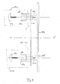
- Fig. 1 is a cross-sectional side view of a supporting device for supporting a sound generator in a housing according to a preferred embodiment of the present invention.
- a reference numeral in Fig. 1 illustrates a housing in which the sound generator is accommodated and it is to be noted that the housing also accommodates a image generating device such as a cathode ray tube (CRT), a color cathode ray tube or a flat screen.
- the sound generator 100 and the image generating device are components of, but are not restricted to, a television set, a personal computer (PC), an information display apparatus etc.
- the sound generator 100 is fixed to a bracket 101 which is provided as a component being separate from the housing 105.
- the sound generator 100 consists of a single loudspeaker which converts an electric signal into sound waves.
- more than one loudspeaker 100 can be arranged on the bracket 101. It is preferable, e.g. to mount at least two loudspeakers onto the bracket 101 wherein one loudspeaker is adapted for generating sound at high audible frequencies and the other loudspeaker is adapted for the generating sound at low audible frequencies.
- the housing 105 includes a grill 106 facing the sound generator 100 for transmitting the sound generated by the loudspeaker(s) to the outside of the housing 105.
- the housing 105 has mounting bosses 107a and 107b onto which fixing elements 103a, 103b may be fixed.
- the bracket 101 on which the sound generator 100 is mounted may be fixed to the housing 105, respectively to the bosses 107a, 107b of the housing 105 by means of fastening means 104a, 104b. It is obvious for the skilled person, that one fastening means 104a may be sufficient to fasten the bracket 101 to the housing 105. Nevertheless, the invention comprises the use of one or more fastening means 104a, 104b for fastening the bracket 101 to the housing 105. In the embodiment shown in Fig. 1 two fastening means 104a and 104b are provided.
- the fastening means 104a, 104b consists of a fixing element 103a, 103b and a guiding element 102a, 102b.
- the guiding element 102a, 102b engages in the bracket 101, e.g. through a hole.
- the fixing element 103a, 103b is shown as a screw, the diameter of which is less than the diameter of the hole provided in the bracket 101.
- a bushing which is an example of the guiding element 102a, 102b is provided with a projection 110, which may be ring-shaped whereby the outer diameter of the ring is larger than the diameter of the hole in the bracket 101.
- the bracket 101 together with the sound generator 100 is prevented from dropping out to the left side (see Fig. 1) when the fixing element 103a, 103b has been fixed to the mounting bosses 107a, 107b of the housing 105.
- the bracket 101 is able to slide along the guiding element 102a, 102b in a direction substantially parallel to the axis of the sound generator 100, i.e. in a direction parallel to the 1-1' axis (the broken line in Fig. 1).
- the longitudinal movement is stopped by the stopping element consisting of the projection 110 of the guiding element 102a, 102b on one side and the housing 105 on the other side.
- bracket 101 is allowed to vibrate freely together with the sound generator 100 while the sound generator 100 is generating sound resulting in vibrations of the bracket 101 and the sound generator 100.
- the supporting device according to the present invention prevents a transfer of the generated vibrations to the housing 105.
- Fig. 2 illustrates an exploded cross-sectional side view according to another preferred embodiment of the present invention
- Fig. 3 shows the detail A of Fig. 2.
- the supporting device of Fig. 2 exhibits a modified bracket 101 for carrying the sound generator 100.
- the modified bracket 101 comprises at least one lug 108a, 108b the diameter of which is larger than the diameter of the guiding element 102a, 102b.
- the guiding element 102a, 102b may consist of a bushing.
- the bushing 102a, 102b has a circular projection 110 the diameter of which is larger than the inner diameter of the lug 108a, 108b.
- Fig. 2 shows the supporting device for a sound generator 100 in a disassembled state
- Figs. 4 and 5 illustrate the supporting device of Figs. 2 and 3 in an assembled state.
- Fig. 3 represents the detail A of Fig. 2. It is shown in Fig. 3, however, that an elastic element 109 can be provided between the projection 110 of the bushing and the bracket 101 such that the bracket 101 is pushed towards the housing 105 by the action of the elastic element 109.
- the elastic element 109 is a coil spring arranged around the bushing 102a, 102b between the projection 100 of the bushing 102a, 102b and the bracket 101.
- the external diameter of boss 107a, 107b is larger then the diameter of guiding element 102a, 102b on which the bracket 101 is sliding.
- the elastic module of the elastic element 109 is selected in such a way that the bracket 101 together with the sound generator 100 is still capable to move in the direction along the axis 1-1' shown in Fig. 2.
- the elastic element 109 formed as a coil spring has an outer diameter which is larger than the inner diameter of the lug 108a, 108b, whereas the inner diameter of the coil spring is larger than the outer diameter of the bushing 102a, 102b but smaller than the outer diameter of the projection 110 such that the coil spring slides over the bushing 102a, 102b and is stopped by the projection 110 as shown in the detail A of Fig. 3.
- a sliding movement of the bracket 101 with respect to the housing 105 may be damped by means of an absorber element 201 which is provided between the bracket 101 and the housing 105.
- the absorber element 201 has an opening in a portion facing the grill 106 of the housing 105 in order to permit sound passing from the sound generator 100 to the outside of the housing 105.
- the absorber element 201 preferably consists of a foamed material such as foamed plastic or rubber foam.
- the absorber element 201 may consist of any kind of cellular materials or plastics.
- Figs. 4 and 5 show the supporting device of Figs. 2 and 3 in an assembled state.
- the fixing element 103a, 103b consisting of a screw is screwed onto the mounting boss 107a, 107b of the housing 105.
- Fig. 5 shows a detail B of Fig. 4.
- the guiding element 102a formed as a bushing is fixed by the fixing element 103a whereas the lug 108a of the bracket 101 is allowed to move freely along the axis 2-2'
- the supporting device according to the present invention may comprise more than one fastening means 104a, 104b.
- Preferably two fastenings means 104a, 104b are provided as shown in Fig. 4 in order to improve a stability of fastening the bracket 101 carrying the sound generator 100 to the housing 105.
- the sound generator 100 When the sound generator 100 is being installed in the housing 105 at first the sound generator 100 is mounted onto a bracket 101 and secondly the bracket 101 is fastened to the housing 105 using at least one fastening means 104a, 104b, wherein the step of fastening the bracket to the housing includes the insertion of the guiding element 102a, 102b into the bracket 102a, 102b, i.e. the bushing wherein a clearance is provided between the bushing 102a, 102b and the bracket 101, and the fixing of the guiding element 102a, 102b to the housing 105 using the fixing element 103a, 103b such that the bracket 101 is slidably supported by the guiding element 102a, 102b.
- the fixing element 103a, 103b and the guiding element 102a, 102b are provided as a single component used to fasten the bracket 101 to the housing 105. Furthermore, it is an advantage if the mounting bosses 107a, 107b of the housing 105 have threaded bores in which the fixing elements 103a, 103b can be screwed.
- bracket 101 for carrying the sound generator 100 and/or the fixing elements 103a, 103b are made of an elastic material.
- the supporting device supports the sound generator with a loose contact such that vibrations are not transferred to the housing.
- the supporting device according to the present invention is preferably employed in equipment where the sound generation system and an image generation system are both included in one common housing.
Landscapes
- Physics & Mathematics (AREA)
- Engineering & Computer Science (AREA)
- Acoustics & Sound (AREA)
- Signal Processing (AREA)
- Details Of Audible-Bandwidth Transducers (AREA)
Abstract
- 100
- Sound generator
- 101
- Bracket
- 102a, 102b
- Guiding element
- 103a, 103b
- Fixing element
- 104a, 104b
- Fastening means
- 105
- Housing
- 106
- Sound generator grill
- 107a, 107b
- Boss
- 108a, 108b
- Lug
- 109
- Elastic element
- 110
- Projection
- 201
- Absorber element
Description
- The present invention relates to the fastening of sound generators in housings of television sets and/or PC (personal computer) monitors, and in particular to a supporting device for a loudspeaker to be attached to a housing and a method for supporting the sound generator in the housing.
- In consumer electronic products it is of particular importance that a sound generator for generating audible sound and a display device or image generating device, e.g. a cathode ray tube (CRT), a flat screen or a monitor, are arranged in a housing adjacent to each other such that a sound signal accompanies the video or image signal.
- In particular the respective sound generators and the image generating devices display device are enclosed in a single housing.
- The generation of sound using a sound generator is associated with a generation of mechanical vibrations being transferred to the housing, in which the sound generator is arranged. Especially mechanical vibrations in the audio range caused by sound generated by the sound generator involve adverse effects on an image generated by an image generating device included in the housing.
- The main disadvantage of such arrangements is the fact that an acoustic coupling between the sound generator, i.e. the loudspeaker, and a shadow mask of the monitor or the image generating device occurs.
- Especially color cathode ray tubes (CRT) converting electronic signals into a visible color picture by means of three electron beams being scanned vertically and horizontally across an interior surface of the tube are very sensitive to mechanical vibrations. The three electron beams are respectively directed to the same spot at a time and scanned through the whole interior surface of the screen in order to generate a complete image. Each picture element of the screen (pixel) comprises red, blue and green crystals arranged in triads.
- The spots emit light when illuminated by the electron beams due to phosphorescence. Each picture element (pixel) emits light when it is illuminated and thus a color is seen in the light being emitted from a signal pixel whereby the color of the emitted light is determined by the intensity of the three individual electron beams illuminating the color triads in the picture element.
- A complete color image is formed on the screen of the color cathode ray tube being covered by colored light emitting pixels by scanning the three electron beams horizontally and vertically by predetermined amounts. Here the composition of the beam intensities corresponds to the color to be emitted from the picture element being illuminated.
- In order to obtain an acceptable image quality only color triads in one spot must be illuminated at a time. Furthermore an illumination of adjacent triads has to be prevented during a scanning period. A lateral spread at the screen when an illumination by an electron beam takes place causes a degradation of the image quality observed on the screen.
- It is thus a disadvantage if mechanical vibrations of the housing caused by a sound generation are transferred to the image generating device.
- The situation is being aggravated by the fact that in practice a metallic mesh, i.e. a shadow mask is arranged in front of the interior surface of the screen of a color cathode ray tube (CRT). The metallic mesh is provided in order to avoid any illumination of adjacent triads. The metallic mesh has such a structure that only one of the three electron beams is allowed to pass through one hole and to cause an illumination of one triad.
- It is thus obvious that mechanical vibrations of this kind of a metallic mesh exhibits adverse effects on the quality of the image being displayed. It is a disadvantage that especially vibrations in the low frequency audio range caused by a sound generator arranged near by the cathode ray tube lead to excessive vibrations of the metallic mesh and the cathode ray tube on the whole.
- In order to overcome the vibration problems it has been proposed to provide a vibration and shock resistant environment or a cathode ray tube as disclosed in US 4,651,218. In US 4,651,218 a mounting arrangement is presented where elastomeric grommets are provided in a fastening means in order to damp external vibrations. It is, however, a disadvantage of the arrangement described in US 4,651,218 that the cathode ray tube has to be rigidly fixed to its housing due to the heavy weight of the cathode ray tube. The provision of grommets in the fastening means leads to an unsatisfactory vibration damping with respect to vibrations caused by an acoustic sound generator or a loudspeaker.
- In US 4,651,218 an insufficient vibration damping is provided because elastomeric grommets are placed between a fastener (screw) and a lug of the cathode ray tube and also between the cathode ray tube and the housing.
- In the PCT application WO 98/41014 a monitor is proposed which has a tubular loudspeaker reducing mask vibrations of a cathode ray tube arranged adjacent to the loudspeaker system.
- The loudspeaker system is physically integrated with a monitor and comprises an electro-acoustic transducer, a passive radiator and a tube mounted in between them. The tube has a circular cross section and its axis is parallel to the plane of the metallic mesh, i.e. the shadow mask, of the cathode ray tube.
- A tubular housing or enclosure of the transducer includes a hollow elongated cylinder which is mechanical very rigid in the radial direction, thus that radial oscillations/vibrations hardly occur. The tubular housing is mounted in such a way, that its axis is substantially in parallel with a plane of a front panel of the monitor.
- As the shadow mask (metallic mesh) of the cathode ray tube is mainly sensitive to vibrations in its plane an arrangement of the tubular housing such that its axis is essentially in parallel to the mask reduces a mechanical coupling between the loudspeaker and the shadow mask of the cathode ray tube. The tubular housing can be elastically attached to an interior or exterior of the monitor system.
- A disadvantage of the arrangement of WO 98/41014 is that the tubes are fixed to the housing such that still an acoustic coupling between the sound generator and the image generating device is possible resulting in a degraded image quality in many circumstances.
- Fig. 6 shows a supporting device for supporting a
sound generator 100 in ahousing 105. Thesound generator 100 is comprised of at least one loudspeaker which is attached at amounting bracket 101. Themounting bracket 101 is fixed by at least one fastening means (not shown) to the housing of e.g. a television set and/or a PC monitor. -
Absorber elements 201 are shown to be embedded between themounting bracket 101 in thehousing 105. Mechanical vibrations caused by the operation of the sound generator, i.e. by the operation of theloudspeaker 100 are damped by the absorbingelements 201 such that a vibration of thehousing 105 is reduced. Nevertheless, vibrational energy generated by the loudspeaker is transferred to thehousing 105 via theabsorber elements 201. - It is thus a disadvantage of conventional supporting devices that vibrational energy from a sound generator is transferred to the housing in which an image generating device is accommodated.
- Thus the object of the present invention is to provide a supporting device for supporting a sound generator in a housing wherein a transfer of vibrational energy to the housing is eliminated.
- This object is achieved by a supporting device for supporting a sound generator in a housing comprising the features of
claim 1. - Furthermore the object is achieved by a method for supporting a sound generator in a housing according to claim 16.
- Further aspects of the present invention follow from the dependent claims.
- According to one aspect of the invention is to provide a supporting device such that a mounting bracket where the sound generator is mounted is capable to slide on a guiding element engaging in the bracket.
- Hence, it is an advantage of the present invention that mechanical vibrations caused by the sound generator cannot be transferred to the housing in which an image generating device such as a cathode ray tube or a monitor is accommodated.
- It is a further advantage of the present invention that an assembly of the sound generator and the housing requires much less workmanship compared to conventional supporting devices for sound generators.
- It is advantageous that it is not required that components such as fixing elements, guiding elements and bushings have narrow specifications. Furthermore it is an advantage of the present invention that a transfer of vibrational energy to the housing is eliminated over a wide range of sound frequencies.
- The supporting device for supporting a sound generator in a housing according to the present invention essentially comprises a bracket for carrying the sound generator and at least one fastening means for fastening the bracket to the housing, wherein the fastening means includes a guiding element engaging in the bracket wherein a clearance is provided between the guiding element and the bracket, and a fixing element for fixing the guiding element to the housing such that the bracket is slidably supported by the guiding element.
- Furthermore, the method for supporting a sound generator in a housing according to the present invention essentially involves the following steps: mounting the sound generator onto a bracket and fastening the bracket to the housing using at least one fastening means, wherein the step of fastening the bracket to the housing is performed by inserting the bracket into a guiding element wherein a clearance is provided between the guiding element and the bracket, and by fixing the guiding element to the housing using a fixing element such that the bracket is slidably supported by the guiding element.
- According to an aspect of the present invention the sound generator comprises at least one loudspeaker for generating audible sound. It is preferable that a loudspeaker system consists of at least two loudspeakers whereby one loudspeaker is adapted to generate high audible frequencies and one loudspeaker is adapted to generate low audible frequencies.
- According to another aspect of the present invention the housing comprises a grill facing the sound generator for transmitting sound to the outside of the housing.
- According to yet another aspect of the present invention the housing comprises at least one boss where the fixing element is attachable. It is preferred that the boss is rigid and provides a secure fastening of the guiding element.
- Preferably the bracket comprises at least one lug wherein the guiding element slides with a clearance. It is advantageous that at least two lugs are provided on the bracket in order to slidably mount the bracket in the housing at two distinct locations.
- According to yet another aspect of the present invention the guiding element engaging in the bracket consists of a bushing formed with a projection acting as a stopper element for holding the bracket in such a way that the bracket cannot drop from the guiding element.
- In a preferred manner the bushing is fixed to the at least one boss arranged in the housing by means of at least one fixing element such that the bushing slides within the lug.
- It is to be preferred that the fixing consists of a screw or clamp in order to screw or clamp the guiding element to the housing. Furthermore it is possible that the fixing element and the guiding element are produced in one single component in order to facilitate a mounting of the bracket to the housing.
- Moreover it is advantageous if the screw is made of an elastic material which has a long flat surface in order to slidably hold bracket with the sound generator.
- According to yet another aspect of the present invention the bracket for carrying the sound generator and/or the fixing element for fixing the guiding element to the housing such that the bracket is slidably supported by the guiding element are made of an elastic material. Preferably the elastic material consists of plastic or a composition containing plastic.
- According to yet another aspect of the present invention an elastic element is provided between the projection of the bushing and the bracket such that the bracket is pushed towards the housing by the action of the elastic element. It is thus possible to slightly push the bracket carrying the sound generator towards the housing in order to prevent a bouncing of the bracket with respect to the housing.
- Preferably, the elastic element is formed as a coil spring, i.e. a spiral spring, wound or arranged around the bushing between the projection of the bushing and the bracket.
- According to yet another aspect of the present invention an absorber element is provided between the bracket and the housing such that a sliding movement of the bracket with respect to the housing is damped.
- It is to be preferred that the absorber element consists of a foamed material such as foamed plastic, rubber foam, cellular material, granulated foam plastic expanded material, etc.
- According to yet another aspect of the present invention an image generating device for generating an image is accommodated in the housing where the sound generator is arranged. The image generating device includes a monitor, e.g. for personal computers (PC), a cathode ray tube or a color cathode ray tube (CRT) for a television set, a display screen for advertisement etc.
- According to yet another aspect of the present invention the guiding element is screwed or clamped onto a boss arranged in the housing by means of the fixing element.
- It is preferred that the bracket is pushed towards the housing by the action of an elastic element which is provided between the projection of the guiding element, e.g. the bushing and the bracket.
- According to yet another aspect of the present invention a sliding movement of the bracket with respect to the housing is damped by means of an absorber element which is provided between the bracket and the housing.
- Embodiments of the present invention are depicted in the drawings and are explained in more detail in the following description.
- In the drawings:
- Fig. 1
- is a cross-sectional side view of a supporting device for supporting a sound generator in a housing according to a preferred embodiment of the present invention;
- Fig. 2
- is an exploded side view of a supporting device comprising a bracket with fastening lugs according to another preferred embodiment of the present invention;
- Fig. 3
- illustrates a detail of the fastening means labeled A in Fig. 2;
- Fig. 4
- represents a cross-sectional side view of the supporting device according to the preferred embodiment of the present invention shown in Fig. 2 where the supporting device is shown in its assembled state;
- Fig. 5
- is a detailed view of a fastening means wherein the detail is labeled by B in Fig. 4; and
- Fig. 6
- a conventional supporting device for supporting a sound generator in a housing.
- In the figures same reference numerals are related to same components or components having the same technical features and functions.
- The present invention now will be described more fully hereinafter with reference to accompanying drawings in which preferred embodiments of the present invention are shown.
- Fig. 1 is a cross-sectional side view of a supporting device for supporting a sound generator in a housing according to a preferred embodiment of the present invention. A reference numeral in Fig. 1 illustrates a housing in which the sound generator is accommodated and it is to be noted that the housing also accommodates a image generating device such as a cathode ray tube (CRT), a color cathode ray tube or a flat screen. The
sound generator 100 and the image generating device are components of, but are not restricted to, a television set, a personal computer (PC), an information display apparatus etc. - As shown in Fig. 1 the
sound generator 100 is fixed to abracket 101 which is provided as a component being separate from thehousing 105. In the embodiment shown in Fig. 1 thesound generator 100 consists of a single loudspeaker which converts an electric signal into sound waves. - Though not shown it is obvious for a skilled person that more than one
loudspeaker 100 can be arranged on thebracket 101. It is preferable, e.g. to mount at least two loudspeakers onto thebracket 101 wherein one loudspeaker is adapted for generating sound at high audible frequencies and the other loudspeaker is adapted for the generating sound at low audible frequencies. - In an area facing the loudspeaker the
housing 105 includes agrill 106 facing thesound generator 100 for transmitting the sound generated by the loudspeaker(s) to the outside of thehousing 105. In the embodiment shown in Fig. 1 thehousing 105 has mountingbosses elements 103a, 103b may be fixed. - The
bracket 101 on which thesound generator 100 is mounted, may be fixed to thehousing 105, respectively to thebosses housing 105 by means of fastening means 104a, 104b. It is obvious for the skilled person, that one fastening means 104a may be sufficient to fasten thebracket 101 to thehousing 105. Nevertheless, the invention comprises the use of one or more fastening means 104a, 104b for fastening thebracket 101 to thehousing 105. In the embodiment shown in Fig. 1 two fastening means 104a and 104b are provided. - The fastening means 104a, 104b consists of a fixing
element 103a, 103b and a guidingelement 102a, 102b. The guidingelement 102a, 102b engages in thebracket 101, e.g. through a hole. In Fig. 1 the fixingelement 103a, 103b is shown as a screw, the diameter of which is less than the diameter of the hole provided in thebracket 101. - Furthermore, a bushing which is an example of the guiding
element 102a, 102b is provided with a projection 110, which may be ring-shaped whereby the outer diameter of the ring is larger than the diameter of the hole in thebracket 101. Thus, thebracket 101 together with thesound generator 100 is prevented from dropping out to the left side (see Fig. 1) when the fixingelement 103a, 103b has been fixed to the mountingbosses housing 105. - When the fastening means 104a, 104b is fixed at the
housing 105, i.e. when the fixingelement 103a, 103b is fixed to theboss housing 105 thebracket 101 is able to slide along the guidingelement 102a, 102b in a direction substantially parallel to the axis of thesound generator 100, i.e. in a direction parallel to the 1-1' axis (the broken line in Fig. 1). - The longitudinal movement is stopped by the stopping element consisting of the projection 110 of the guiding
element 102a, 102b on one side and thehousing 105 on the other side. - Thus the
bracket 101 is allowed to vibrate freely together with thesound generator 100 while thesound generator 100 is generating sound resulting in vibrations of thebracket 101 and thesound generator 100. In this manner the supporting device according to the present invention prevents a transfer of the generated vibrations to thehousing 105. - Mechanical energy generated by the
sound generator 100 caused by the acoustic emission of sound is not absorbed by thehousing 105 and cannot degrade the image quality of a monitor installed nearby. Mechanical energy generated by thesound generator 100 cannot be transferred to thehousing 105. Thus, the image quality of a display device, e.g. a monitor, installed nearby thesound generator 100 cannot be degraded due to vibrations caused by thesound generator 100. - Fig. 2 illustrates an exploded cross-sectional side view according to another preferred embodiment of the present invention, and Fig. 3 shows the detail A of Fig. 2.
- It is noted that same reference numerals are given to same parts or components as in Fig. 1 and their description is omitted here. In addition to the supporting device shown in Fig. 1, the supporting device of Fig. 2 exhibits a modified
bracket 101 for carrying thesound generator 100. - The modified
bracket 101 comprises at least onelug 108a, 108b the diameter of which is larger than the diameter of the guidingelement 102a, 102b. As described with reference to Fig. 1 the guidingelement 102a, 102b may consist of a bushing. - The
bushing 102a, 102b has a circular projection 110 the diameter of which is larger than the inner diameter of thelug 108a, 108b. Fig. 2 shows the supporting device for asound generator 100 in a disassembled state, whereas Figs. 4 and 5 illustrate the supporting device of Figs. 2 and 3 in an assembled state. - Fig. 3 represents the detail A of Fig. 2. It is shown in Fig. 3, however, that an
elastic element 109 can be provided between the projection 110 of the bushing and thebracket 101 such that thebracket 101 is pushed towards thehousing 105 by the action of theelastic element 109. Preferably theelastic element 109 is a coil spring arranged around thebushing 102a, 102b between theprojection 100 of thebushing 102a, 102b and thebracket 101. Preferably, the external diameter ofboss element 102a, 102b on which thebracket 101 is sliding. - It is noted that the elastic module of the
elastic element 109 is selected in such a way that thebracket 101 together with thesound generator 100 is still capable to move in the direction along the axis 1-1' shown in Fig. 2. - Furthermore, the
elastic element 109 formed as a coil spring has an outer diameter which is larger than the inner diameter of thelug 108a, 108b, whereas the inner diameter of the coil spring is larger than the outer diameter of thebushing 102a, 102b but smaller than the outer diameter of the projection 110 such that the coil spring slides over thebushing 102a, 102b and is stopped by the projection 110 as shown in the detail A of Fig. 3. - A sliding movement of the
bracket 101 with respect to thehousing 105 may be damped by means of anabsorber element 201 which is provided between thebracket 101 and thehousing 105. Preferably theabsorber element 201 has an opening in a portion facing thegrill 106 of thehousing 105 in order to permit sound passing from thesound generator 100 to the outside of thehousing 105. Theabsorber element 201 preferably consists of a foamed material such as foamed plastic or rubber foam. Furthermore, theabsorber element 201 may consist of any kind of cellular materials or plastics. - Figs. 4 and 5 show the supporting device of Figs. 2 and 3 in an assembled state. As can be seen from Fig. 4 the fixing
element 103a, 103b consisting of a screw is screwed onto the mountingboss housing 105. - Fig. 5 shows a detail B of Fig. 4. The guiding
element 102a formed as a bushing is fixed by the fixingelement 103a whereas thelug 108a of thebracket 101 is allowed to move freely along the axis 2-2' - The supporting device according to the present invention may comprise more than one fastening means 104a, 104b. Preferably two fastenings means 104a, 104b are provided as shown in Fig. 4 in order to improve a stability of fastening the
bracket 101 carrying thesound generator 100 to thehousing 105. - When the
sound generator 100 is being installed in thehousing 105 at first thesound generator 100 is mounted onto abracket 101 and secondly thebracket 101 is fastened to thehousing 105 using at least one fastening means 104a, 104b, wherein the step of fastening the bracket to the housing includes the insertion of the guidingelement 102a, 102b into thebracket 102a, 102b, i.e. the bushing wherein a clearance is provided between thebushing 102a, 102b and thebracket 101, and the fixing of the guidingelement 102a, 102b to thehousing 105 using thefixing element 103a, 103b such that thebracket 101 is slidably supported by the guidingelement 102a, 102b. - In'the assembled state shown in Fig. 4 sound is permitted to pass through the
grill 106 of thehousing 105 whereby any vibrations caused by thesound generator 100 are not transmitted to thehousing 105 as the bracket is freely movable along the axis 2-2' by a sliding of thelugs 108a, 108b along the guidingelements 102a, 102b. Furthermore thebracket 101 is pushed towards the housing by the action of the -elastic element 109, which is arranged between the projection 110 of the guidingelement 102a, 102b and the bracket 101 (Fig. 3). - Moreover a sliding movement of the
bracket 101 with respect to thehousing 105 is damped by a means of theabsorber element 201 which is arranged between thebracket 101 and thehousing 105. - It is advantageous if the fixing
element 103a, 103b and the guidingelement 102a, 102b are provided as a single component used to fasten thebracket 101 to thehousing 105. Furthermore, it is an advantage if the mountingbosses housing 105 have threaded bores in which thefixing elements 103a, 103b can be screwed. - Furthermore, an additional vibration damping effect can be obtained, if the
bracket 101 for carrying thesound generator 100 and/or the fixingelements 103a, 103b are made of an elastic material. - The supporting device according to the present invention supports the sound generator with a loose contact such that vibrations are not transferred to the housing.
- The supporting device according to the present invention is preferably employed in equipment where the sound generation system and an image generation system are both included in one common housing.
- As for the description of a conventional supporting device for supporting a sound generator illustrated in Fig. 6 it is referred to the introduction of this description.
- While preferred embodiments have been shown and described, various modifications and substitutions may be made thereto without departing from the spirit and scope of the invention.
- Accordingly it is to be understood that the present invention has been described by way of illustration and not limitation.
- Furthermore the invention is not limited to the specific application areas mentioned above.
Claims (25)
- A supporting device for supporting a sound generator (100) in a housing (105) comprising:characterised in that the fastening means (104a, 104b) includes:a) a bracket (101) for carrying the sound generator (100); andb) at least one fastening means (104a, 104b) for fastening the bracket (101) to the housing (105);b1) a guiding element (102a, 102b) engaging in the bracket (101) wherein a clearance is provided between the guiding element (102a, 102b) and the bracket (101); andb2) a fixing element (103a, 103b) for fixing the guiding element (102a, 102b) to the housing (105) such that the bracket (101) is slidably supported by the guiding element (102a, 102b).
- A device according to claim 1,
characterised in that the sound generator (100) comprises at least one loudspeaker for generating audible sound. - A device according to claim 1 or 2,
characterised in that the housing (105) comprises a grill (106) facing the sound generator (100) for transmitting sound to the outside of the housing (105). - A device according to claim 1,
characterised in that the housing (105) comprises at least one boss (107a, 107b) where the fixing element (103a, 103b) is attachable. - A device according to claim 1,
characterised in that the bracket (101) comprises at least one lug (108a, 108b) wherein the guiding element (102a, 102b) slides within the lug (108a, 108b) with a clearance. - A device according to claim 1,
characterised in that the guiding element (102a, 102b) engaging in the bracket (101) consists of a bushing formed with a projection (110) acting as a stopper element for holding the bracket (101). - A device according to claim 4, 5 and 6,
characterised in that the bushing is fixed to the boss (107a, 107b) of the housing (105) using the fixing element (103a, 103b) such that the bushing slides within the lug (108a, 108b). - A device according to claim 1,
characterised in that the fixing element (103a, 103b) consists of a screw or a clamp. - A device according to claim 1,
characterised in that the bracket (101) for carrying the sound generator (100) and/or the fixing element (103a, 103b) are made of an elastic material. - A device according to claim 6,
characterised in that an elastic element (109) is provided between the projection (110) of the bushing (102a, 102b) and the bracket (101) such that the bracket (101) is pushed towards the housing (105) by the action of the elastic element (109). - A device according to claim 10,
characterised in that the elastic element (109) is a coil spring arranged around the bushing (102a, 102b) between the projection (110) of the bushing (102a, 102b) and the bracket (101). - A device according to claim 1,
characterised in that an absorber element (201) is provided between the bracket (101) and the housing (105) such that a sliding movement of the bracket (101) with respect to the housing (105) is damped. - A device according to claim 12,
characterised in that the absorber element (201) consists of a foamed material such as foamed plastic or rubber foam. - A device according to claim 1,
characterised in that a display device for displaying an image is accommodated in the housing (105) where the sound generator (100) is arranged. - A television set comprising a supporting device according to claims 1 to 14.
- A method for supporting a sound generator (100) in a housing (105) comprising the following steps:characterised in that the step of fastening the bracket (101) to the housing (105) includes:a) mounting the sound generator (100) onto a bracket (101); andb) fastening the bracket (101) to the housing (105) using at least one fastening means (104a, 104b);b1) inserting the bracket (101) into a guiding element (102a, 102b) wherein a clearance is provided between the guiding element (102a, 102b) and the bracket (101); andb2) fixing the guiding element (102a, 102b) to the housing (105) using a fixing element (103a, 103b) such that the bracket (101) is slidably supported by the guiding element (102a, 102b).
- A method according to claim 16,
characterised in that sound generated by the sound generator (100) is transmitted to the outside of the housing (105) via a grill (106) provided in the housing (105) and facing the sound generator (100). - A method according to claim 16,
characterised in that the guiding element (102a, 102b) slides on a lug (108a, 108b) provided in the bracket (101). - A method according to claim 16,
characterised in that bracket (101) is supported on the the guiding element (102a, 102b) by means of a projection (110) formed on the guiding element (102a, 102b). - A method according to claim 18,
characterised in that the guiding element (102a, 102b) is fixed to a boss (107a, 107b) of the housing (105) using the fixing element (103a, 103b) such that the guiding element (102a, 102b) slides within the lug (108a, 108b). - A method according to claim 20,
characterised in that the guiding element (102a, 102b) is screwed or clamped onto the boss (107a, 107b) by means of the fixing element (103a, 103b). - A method according to claim 19,
characterised in that the bracket (101) is pushed towards the housing (105) by the action of an elastic element (109) which is provided between the projection (110) of the guiding element (102a, 102b) and the bracket (101). - A method according to claim 22,
characterised in that the elastic element (109) is arranged as a coil spring around the guiding element (102a, 102b) between the projection (110) of the guiding elment (102a, 102b) and the bracket (101). - A method according to claim 16,
characterised in that a sliding movement of the bracket (101) with respect to the housing (105) is damped by means of an absorber element (201) which is provided between the bracket (101) and the housing (105). - A method according to claim 16,
characterised in that the fixing element (103a, 103b) and the guiding element (102a, 102b) are provided as a single component to fasten the bracket (101) to the housing (105).
Priority Applications (2)
| Application Number | Priority Date | Filing Date | Title |
|---|---|---|---|
| DE60335259T DE60335259D1 (en) | 2003-08-06 | 2003-08-06 | Holding device for a tone generator |
| EP20030017536 EP1505851B1 (en) | 2003-08-06 | 2003-08-06 | Supporting device for sound generator |
Applications Claiming Priority (1)
| Application Number | Priority Date | Filing Date | Title |
|---|---|---|---|
| EP20030017536 EP1505851B1 (en) | 2003-08-06 | 2003-08-06 | Supporting device for sound generator |
Publications (2)
| Publication Number | Publication Date |
|---|---|
| EP1505851A1 true EP1505851A1 (en) | 2005-02-09 |
| EP1505851B1 EP1505851B1 (en) | 2010-12-08 |
Family
ID=33547616
Family Applications (1)
| Application Number | Title | Priority Date | Filing Date |
|---|---|---|---|
| EP20030017536 Expired - Lifetime EP1505851B1 (en) | 2003-08-06 | 2003-08-06 | Supporting device for sound generator |
Country Status (2)
| Country | Link |
|---|---|
| EP (1) | EP1505851B1 (en) |
| DE (1) | DE60335259D1 (en) |
Cited By (2)
| Publication number | Priority date | Publication date | Assignee | Title |
|---|---|---|---|---|
| EP2429213A1 (en) * | 2010-09-08 | 2012-03-14 | HannStar Display Corp. | Fixing mechanism |
| WO2024006026A1 (en) * | 2022-06-30 | 2024-01-04 | Innovative Technology Electronics, Llc | Phonograph record player with speaker |
Citations (3)
| Publication number | Priority date | Publication date | Assignee | Title |
|---|---|---|---|---|
| US4651218A (en) * | 1985-04-24 | 1987-03-17 | Smiths Industries Aerospace & Defense Systems Inc. | Method and apparatus for mounting a CRT in a dynamic (vibration and shock prone) environment |
| EP1179968A2 (en) * | 2000-08-10 | 2002-02-13 | Shima System Co., Ltd. | Structure around a speaker unit |
| WO2003056411A1 (en) * | 2001-12-27 | 2003-07-10 | Lg Electronics, Inc. | Hinge structure for flat visual display device |
-
2003
- 2003-08-06 EP EP20030017536 patent/EP1505851B1/en not_active Expired - Lifetime
- 2003-08-06 DE DE60335259T patent/DE60335259D1/en not_active Expired - Lifetime
Patent Citations (3)
| Publication number | Priority date | Publication date | Assignee | Title |
|---|---|---|---|---|
| US4651218A (en) * | 1985-04-24 | 1987-03-17 | Smiths Industries Aerospace & Defense Systems Inc. | Method and apparatus for mounting a CRT in a dynamic (vibration and shock prone) environment |
| EP1179968A2 (en) * | 2000-08-10 | 2002-02-13 | Shima System Co., Ltd. | Structure around a speaker unit |
| WO2003056411A1 (en) * | 2001-12-27 | 2003-07-10 | Lg Electronics, Inc. | Hinge structure for flat visual display device |
Cited By (2)
| Publication number | Priority date | Publication date | Assignee | Title |
|---|---|---|---|---|
| EP2429213A1 (en) * | 2010-09-08 | 2012-03-14 | HannStar Display Corp. | Fixing mechanism |
| WO2024006026A1 (en) * | 2022-06-30 | 2024-01-04 | Innovative Technology Electronics, Llc | Phonograph record player with speaker |
Also Published As
| Publication number | Publication date |
|---|---|
| DE60335259D1 (en) | 2011-01-20 |
| EP1505851B1 (en) | 2010-12-08 |
Similar Documents
| Publication | Publication Date | Title |
|---|---|---|
| RU2195792C2 (en) | Facility to mount loudspeaker on display equipment | |
| US5920637A (en) | Audio induced interference suppression apparatus for video display appliances | |
| JP2003134584A (en) | Speaker system for video display equipment | |
| CN102652436A (en) | Speaker retaining mechanism and television receiver comprising same | |
| RU2138135C1 (en) | Structure of case of loudspeaker for information display devices | |
| MXPA96003107A (en) | Structure of altoparlate box for vi display appliances | |
| JP2014154922A (en) | Display device and television receiver | |
| EP1505851B1 (en) | Supporting device for sound generator | |
| US5903656A (en) | Monitor has tubular loudspeaker reducing CRT's mask vibrations | |
| JP3998618B2 (en) | Display device | |
| AU691750B2 (en) | Howling phenomena removing apparatus for video display apparatus | |
| JP2001309277A (en) | TV speaker mounting structure | |
| EP0904657B1 (en) | Monitor has tubular loudspeaker reducing crt's mask vibrations | |
| JP2009033421A (en) | Speaker device, and projector device using the same | |
| KR20040020043A (en) | CRT vibration and shock isolating mount | |
| KR970010039B1 (en) | Howling prevention device for shadow mask for flat color CRT | |
| KR0158270B1 (en) | Apparatus for preventing vibration from monitor or tv picture of monitor by speaker output | |
| JP2014225749A (en) | Display device | |
| US6204830B1 (en) | Monitor having base with sound reproducing element for providing sound frequencies at self-resonant frequency | |
| JP2002252892A (en) | Speaker holding device for video display equipment | |
| KR0162971B1 (en) | An apparatus for preventing vibration from picture by speaker output in image displayer | |
| KR0184048B1 (en) | The structure for preventing screen vibration by speaker of image displayer | |
| JP2003219319A (en) | Image display device and color cathode ray tube used therein | |
| KR100232822B1 (en) | Flat cathode-ray tube | |
| JP2015128246A (en) | Speaker system |
Legal Events
| Date | Code | Title | Description |
|---|---|---|---|
| PUAI | Public reference made under article 153(3) epc to a published international application that has entered the european phase |
Free format text: ORIGINAL CODE: 0009012 |
|
| AK | Designated contracting states |
Kind code of ref document: A1 Designated state(s): AT BE BG CH CY CZ DE DK EE ES FI FR GB GR HU IE IT LI LU MC NL PT RO SE SI SK TR |
|
| AX | Request for extension of the european patent |
Extension state: AL LT LV MK |
|
| 17P | Request for examination filed |
Effective date: 20050615 |
|
| AKX | Designation fees paid |
Designated state(s): DE FR GB |
|
| GRAP | Despatch of communication of intention to grant a patent |
Free format text: ORIGINAL CODE: EPIDOSNIGR1 |
|
| GRAC | Information related to communication of intention to grant a patent modified |
Free format text: ORIGINAL CODE: EPIDOSCIGR1 |
|
| GRAS | Grant fee paid |
Free format text: ORIGINAL CODE: EPIDOSNIGR3 |
|
| GRAA | (expected) grant |
Free format text: ORIGINAL CODE: 0009210 |
|
| AK | Designated contracting states |
Kind code of ref document: B1 Designated state(s): DE FR GB |
|
| REG | Reference to a national code |
Ref country code: GB Ref legal event code: FG4D |
|
| REF | Corresponds to: |
Ref document number: 60335259 Country of ref document: DE Date of ref document: 20110120 Kind code of ref document: P |
|
| REG | Reference to a national code |
Ref country code: DE Ref legal event code: R082 Ref document number: 60335259 Country of ref document: DE Representative=s name: LEONHARD OLGEMOELLER FRICKE, DE Ref country code: DE Ref legal event code: R082 Ref document number: 60335259 Country of ref document: DE Representative=s name: LEONHARD & PARTNER PATENTANWAELTE, DE |
|
| PLBE | No opposition filed within time limit |
Free format text: ORIGINAL CODE: 0009261 |
|
| STAA | Information on the status of an ep patent application or granted ep patent |
Free format text: STATUS: NO OPPOSITION FILED WITHIN TIME LIMIT |
|
| 26N | No opposition filed |
Effective date: 20110909 |
|
| REG | Reference to a national code |
Ref country code: DE Ref legal event code: R097 Ref document number: 60335259 Country of ref document: DE Effective date: 20110909 |
|
| REG | Reference to a national code |
Ref country code: FR Ref legal event code: PLFP Year of fee payment: 14 |
|
| REG | Reference to a national code |
Ref country code: FR Ref legal event code: PLFP Year of fee payment: 15 |
|
| REG | Reference to a national code |
Ref country code: FR Ref legal event code: PLFP Year of fee payment: 16 |
|
| PGFP | Annual fee paid to national office [announced via postgrant information from national office to epo] |
Ref country code: GB Payment date: 20220823 Year of fee payment: 20 Ref country code: DE Payment date: 20220819 Year of fee payment: 20 |
|
| PGFP | Annual fee paid to national office [announced via postgrant information from national office to epo] |
Ref country code: FR Payment date: 20220823 Year of fee payment: 20 |
|
| REG | Reference to a national code |
Ref country code: DE Ref legal event code: R082 Ref document number: 60335259 Country of ref document: DE Representative=s name: LEONHARD, REIMUND, DIPL.-ING., DE |
|
| REG | Reference to a national code |
Ref country code: DE Ref legal event code: R071 Ref document number: 60335259 Country of ref document: DE |
|
| REG | Reference to a national code |
Ref country code: GB Ref legal event code: PE20 Expiry date: 20230805 |
|
| PG25 | Lapsed in a contracting state [announced via postgrant information from national office to epo] |
Ref country code: GB Free format text: LAPSE BECAUSE OF EXPIRATION OF PROTECTION Effective date: 20230805 |