EP1505837A1 - Device and method for compressing digital images - Google Patents
Device and method for compressing digital images Download PDFInfo
- Publication number
- EP1505837A1 EP1505837A1 EP04077277A EP04077277A EP1505837A1 EP 1505837 A1 EP1505837 A1 EP 1505837A1 EP 04077277 A EP04077277 A EP 04077277A EP 04077277 A EP04077277 A EP 04077277A EP 1505837 A1 EP1505837 A1 EP 1505837A1
- Authority
- EP
- European Patent Office
- Prior art keywords
- block
- image
- quality
- enhancement layer
- comprises means
- Prior art date
- Legal status (The legal status is an assumption and is not a legal conclusion. Google has not performed a legal analysis and makes no representation as to the accuracy of the status listed.)
- Granted
Links
- 238000000034 method Methods 0.000 title claims description 13
- 238000001914 filtration Methods 0.000 claims description 34
- 235000019557 luminance Nutrition 0.000 claims description 19
- 239000013598 vector Substances 0.000 claims description 18
- 230000000694 effects Effects 0.000 claims description 17
- 238000006073 displacement reaction Methods 0.000 claims description 10
- 230000015556 catabolic process Effects 0.000 claims description 4
- 238000006731 degradation reaction Methods 0.000 claims description 4
- PXFBZOLANLWPMH-UHFFFAOYSA-N 16-Epiaffinine Natural products C1C(C2=CC=CC=C2N2)=C2C(=O)CC2C(=CC)CN(C)C1C2CO PXFBZOLANLWPMH-UHFFFAOYSA-N 0.000 claims description 3
- 230000006870 function Effects 0.000 description 30
- 230000005540 biological transmission Effects 0.000 description 12
- 230000006835 compression Effects 0.000 description 9
- 238000007906 compression Methods 0.000 description 9
- 238000013139 quantization Methods 0.000 description 6
- 230000001419 dependent effect Effects 0.000 description 5
- 230000007547 defect Effects 0.000 description 4
- 230000008901 benefit Effects 0.000 description 3
- 230000006735 deficit Effects 0.000 description 3
- 238000004364 calculation method Methods 0.000 description 2
- 238000012935 Averaging Methods 0.000 description 1
- 238000000354 decomposition reaction Methods 0.000 description 1
- 238000010586 diagram Methods 0.000 description 1
- 230000006872 improvement Effects 0.000 description 1
- 230000000873 masking effect Effects 0.000 description 1
- 238000005259 measurement Methods 0.000 description 1
- 238000005192 partition Methods 0.000 description 1
- 230000008569 process Effects 0.000 description 1
- 230000000717 retained effect Effects 0.000 description 1
- 230000009466 transformation Effects 0.000 description 1
Images


Classifications
-
- H—ELECTRICITY
- H04—ELECTRIC COMMUNICATION TECHNIQUE
- H04N—PICTORIAL COMMUNICATION, e.g. TELEVISION
- H04N19/00—Methods or arrangements for coding, decoding, compressing or decompressing digital video signals
- H04N19/30—Methods or arrangements for coding, decoding, compressing or decompressing digital video signals using hierarchical techniques, e.g. scalability
-
- H—ELECTRICITY
- H04—ELECTRIC COMMUNICATION TECHNIQUE
- H04N—PICTORIAL COMMUNICATION, e.g. TELEVISION
- H04N19/00—Methods or arrangements for coding, decoding, compressing or decompressing digital video signals
- H04N19/30—Methods or arrangements for coding, decoding, compressing or decompressing digital video signals using hierarchical techniques, e.g. scalability
- H04N19/34—Scalability techniques involving progressive bit-plane based encoding of the enhancement layer, e.g. fine granular scalability [FGS]
-
- H—ELECTRICITY
- H04—ELECTRIC COMMUNICATION TECHNIQUE
- H04N—PICTORIAL COMMUNICATION, e.g. TELEVISION
- H04N19/00—Methods or arrangements for coding, decoding, compressing or decompressing digital video signals
- H04N19/10—Methods or arrangements for coding, decoding, compressing or decompressing digital video signals using adaptive coding
- H04N19/102—Methods or arrangements for coding, decoding, compressing or decompressing digital video signals using adaptive coding characterised by the element, parameter or selection affected or controlled by the adaptive coding
- H04N19/115—Selection of the code volume for a coding unit prior to coding
-
- H—ELECTRICITY
- H04—ELECTRIC COMMUNICATION TECHNIQUE
- H04N—PICTORIAL COMMUNICATION, e.g. TELEVISION
- H04N19/00—Methods or arrangements for coding, decoding, compressing or decompressing digital video signals
- H04N19/10—Methods or arrangements for coding, decoding, compressing or decompressing digital video signals using adaptive coding
- H04N19/134—Methods or arrangements for coding, decoding, compressing or decompressing digital video signals using adaptive coding characterised by the element, parameter or criterion affecting or controlling the adaptive coding
- H04N19/154—Measured or subjectively estimated visual quality after decoding, e.g. measurement of distortion
-
- H—ELECTRICITY
- H04—ELECTRIC COMMUNICATION TECHNIQUE
- H04N—PICTORIAL COMMUNICATION, e.g. TELEVISION
- H04N19/00—Methods or arrangements for coding, decoding, compressing or decompressing digital video signals
- H04N19/10—Methods or arrangements for coding, decoding, compressing or decompressing digital video signals using adaptive coding
- H04N19/169—Methods or arrangements for coding, decoding, compressing or decompressing digital video signals using adaptive coding characterised by the coding unit, i.e. the structural portion or semantic portion of the video signal being the object or the subject of the adaptive coding
- H04N19/17—Methods or arrangements for coding, decoding, compressing or decompressing digital video signals using adaptive coding characterised by the coding unit, i.e. the structural portion or semantic portion of the video signal being the object or the subject of the adaptive coding the unit being an image region, e.g. an object
- H04N19/176—Methods or arrangements for coding, decoding, compressing or decompressing digital video signals using adaptive coding characterised by the coding unit, i.e. the structural portion or semantic portion of the video signal being the object or the subject of the adaptive coding the unit being an image region, e.g. an object the region being a block, e.g. a macroblock
Definitions
- the present invention pertains to a device and to a method for compressing digital images.
- the compression of a digital image reduces the quantity of data necessary for its transmission via, for example, a telecommunication network such as the Internet network.
- Certain compression standards such as the MPEG-4 standard (Motion Picture Expert Group 4), use a so-called multilayer compression according to which an image, the so-called source image, is compressed by means of a base layer, coding a so-called base image, and of an enhancement layer, coding the deviation or the residual, between the source image and the base image.
- MPEG-4 Motion Picture Expert Group 4
- the transmission of a compressed image can be done by transmitting, firstly, its base layer and then, secondly, its enhancement layer, in the form of binary trains.
- the binary train associated with the enhancement layer has the advantage of being able to be truncated in such a way that, if transmission thereof is performed only partially following, for example, a variation in the transmission throughput in the network, the information transmitted in the correctly received part of the binary train may nevertheless still be used to enhance the image coded by the base layer.
- a residual 101 ( Figure 1), coding enhancement coefficients 101 1 , 101 2 , ...101 n specific to each block of pixels forming the image, is decomposed into various planes MSB, MSB -1 , MSB -2 , MSB -3 and LSB of bits ranked in order of priority, each plane MSB, MSB -1 , MSB -2 , MSB -3 or LSB clustering together bits of like weight in the decomposition of the residual specific to each block.
- these coefficients 101 1 , 101 2 , ...101 n may arise from the discrete cosine transformation DCT of an 8x*8 block of pixels, performed by evaluating the difference between the DCT coefficients of a block of a source image, that is to say of the coded image, and the DCT coefficients of an image processed by a quantization and then by an inverse quantization of its base layer.
- Fine Granularity Scalability within the framework of the MPEG4 standard, has the drawback of using a compression of the residual having an efficiency lower than the efficiency of the compression of the base code. In this way, a compromise between the efficiency of the compression, increased by a base layer of significant size, and the security of the transmission of the base, increased with a base layer of small size, may possibly be made.
- the present invention remedies this drawback. It pertains to a device for compressing a source image by means of a base layer, coding a base image, and of an enhancement layer, coding a residual existing between the source image and the base image, the source image and the base image being structured as blocks of pixels, characterized in that it comprises means for generating the enhancement layer of a block as a function of the quality of restitution of this block, determined by comparing the coding of this block in the source image with the coding of this block in the base image, and/or as a function of information coded by this block of pixels.
- the device in accordance with the invention makes it possible to optimize the generation of the enhancement layer by assigning each block a quantity of bits in the enhancement layer dependent on the base coding of this block so that the final image has a uniform quality of restitution.
- the device in accordance with the invention optimizes the generation of the base layer by allotting more data to blocks of pixels for which an enhancement of the base layer results priority-wise, for example if resolution defects associated with this block are more visible than for other blocks.
- the device comprises means for determining the quality of restitution of the block (k) by means of a formula such as: where (i,j) represents the coordinates of a pixel of the block (k) considered, for example of dimensions 8x8, in the source image (block source ) or in the base image (block, rec ) coded by the base layer, L representing the value of the maximum luminance of the image, for example equal to 255.
- the device comprises means for defining an average quality Psnr avg of restitution of the image and for allocating a greater number of bits in the enhancement layer to the blocks whose restitution quality is less than this average quality Pnsr avg or than a reference quality Pnsr ref obtained on the basis of this average quality, for example by adding a quality margin.
- the device comprises means for comparing the quality psnr k of restitution of the block k with a reference quality psnr ref in such a way as to detect a deviation ⁇ psnr k of quality with respect to this reference psnr ref and means for allotting a number NbBits k of bits of the enhancement layer to this block as a function of this deviation.
- the sum ⁇ psnr is evaluated on the basis of the deviations between the quality of each block and the reference quality, for example by means of a formula such as: where M and N are parameters relating to the index number of each block in the image, a block being considered only if its quality psnr k of restitution is less than the reference quality of restitution (psnr k ⁇ psnr ref ).
- the device comprises means for estimating the quality of restitution of the base layer by estimating the degradation, or the cost CostFlti, of its filtering intended to reduce contrasts between neighbouring blocks and means for allotting to a block (k) of pixels a bigger number NbBits k of bits of the enhancement layer the higher this cost CostFlti.
- the device comprises means for estimating the cost CostFlti of the filtering with the aid of a formula such as: where abs is the absolute value function, and block basefiltered (i,j) - block base (i,j) represents the difference in values of the pixel with coordinates i and j of the base layer after filtering and before filtering.
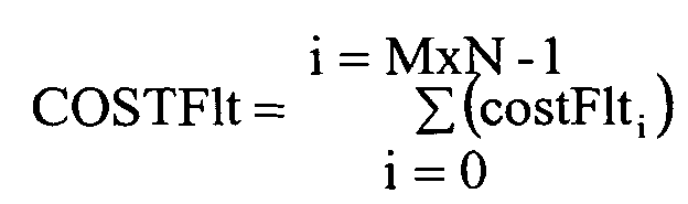
- the device comprises means for determining the cost costFlt of filtering of the image by adding up the costs of filtering of all the blocks of the image, for example with the aid of a formula such as: where i represents a block index number whilst M and N represent the dimensions of the image.
- the device comprises means for generating the enhancement layer of a block as a function of a parameter relating to an average luminance (Lavg) associated with this block, determined for example by adding up the luminances of the pixels of the block considered.
- Lavg average luminance
- the device comprises means for weighting the cost of the filtering of a block as a function of a coefficient F(Lavg i ) whose value depends on the average luminance of this block.
- the device comprises means for weighting the cost of the filtering as a function of a coefficient F(Lavg i ) whose value depends on the texture, or activity, of the considered block of pixels.
- the device comprises means such that the activity Act i of a block i is calculated by means of a formula such as: where k and l are the coordinates of the pixels contained in a block, b i,src being a block of index i of the source image and max (a,b) is equal to a when a is greater than b, and equals b otherwise.
- the device comprises means such that the cost of the filtering of a block is weighted by means of a factor (F(Act i )) dependent on its activity.
- the device comprises means such that the cost of the filtering of a block is weighted by means of a factor F(Vect i ) dependent on the motion vector of this block.
- the device comprises means for generating the enhancement layer by considering the possible exit of the block in an image subsequent to the image considered.
- the device comprises means for generating the enhancement layer by allotting more bits to the blocks of an image if this image is used to generate other images, for example in the case of an inter-image predictive coding.
- the device comprises means for coding the base layer with the aid of a discrete cosine transform.
- the invention also relates to a method for compressing a source image by means of a base layer, coding a base image, and of an enhancement layer, coding a residual existing between the source image and the base image, the source image and the base image being structured as blocks of pixels, characterized in that a device is used which generates the enhancement layer of a block as a function of a quality of restitution of this block, in accordance with one of the preceding claims.
- a coder 210 ( Figure 2) in accordance with the invention can comprise a receiver 211 receiving a signal 212 which codes an image to be compressed. Within the framework of coding in inter-image modes, this receiver 211 subtracts from this signal 212 information already transmitted for a previous image. This operation is performed with the aid of a subtractor 214 which receives a signal 234 corresponding to the information transmitted for the previous images.
- the signal 212 is transformed into a signal 216 14 , which is directed to a transformer 218 which transforms the signal 216 14 , defined in the spatial domain, into a signal 216 18 defined in the frequency domain.
- This operation which is performed with no loss of information, is a discrete cosine transform or DCT.
- the signals 216 18 are transmitted to a quantizer 220 which reduces the dynamic swing of these signals via a quantization operation which involves approximations entailing a non-negligible loss of information of the signal 216 18 .
- the information thus lost during this quantization operation is called the residual (residual information intended for the fgs coder), whereas the information retained after quantization constitutes the base layer of the compressed image.
- the base layer comprises the data received by the coder minus this residual, the latter being coded by the enhancement layer as described later.
- the signal 216 20 is also transmitted to a subtraction loop which comprises an inverse quantizer 224 performing the inverse function of the quantizer 220.
- This inverse quantization operation is performed without any new loss of information.
- IDCT inverse function
- the signal 216 24 is also transmitted to a subtractor 236, forming part of a branch 235 for generating the enhancement layer, a second input of the subtractor 236 receiving the output signal 216 18 from the DCT transformer 218.
- this subtractor 236 performs the subtraction between signals representing the signals received 216 18 and sent 216 24 so as to obtain the residual 216 36 on output from the subtractor 236.
- the branch 235 comprises a memory 238 which stores the residuals (in the spatial frequency domain) imagewise and a device 240 which performs the partition into enhancement planes of the signal 216 38 on exit from the memory 238 according to the standardized method known as "Fine granularity scalability" (FGS) already described.
- FGS Freine granularity scalability
- the branch 235 comprises means 250 for analysing the blocks of pixels compressed in such a way as to determine their quality of restitution, on the basis of the base layer, and for determining, as a function of this quality and of information relating to the coding of the pixels of a block considered, what quantity of bits should be allotted to this block at the enhancement layer level.
- the quality or "psnr k " of restitution is measured, for a block k of pixels, by means of the following formula: where (i,j) represents the coordinates of a pixel of the block considered, for example of dimensions 8x8, in the source image (block source ) or in the reconstructed base image (block, rec ) coded by the base layer.
- the quality of restitution psnr k calculated for each block k of pixels, it is possible to calculate the average quality of restitution psnr avg of the image, for example by averaging the qualities psnr of restitution of each of the blocks of the image or by using a graphical procedure as described later.
- a reference restitution quality psnr avg specific to the image is obtained on the basis of the average quality Psnr avg to which is added a margin, for example, of 3 dB.
- Pnsr ref Psnr avg + 3 dB.
- each measurement of restitution quality psnr k is compared with the reference psnr ref to detect a possible defect ⁇ psnr k of quality of restitution, that is to say a deficit in terms of quality of restitution with respect to the threshold psnr ref defined.
- NbBits k ⁇ psnr k ⁇ psnr ⁇ throughput fgs
- throughput fgs corresponds to the throughput allotted to the image within the framework of the coding dedicated to the enhancement layer
- ⁇ psnr represents the global deficit of the image, evaluated on the basis of the deviations between the quality of each and the reference quality, for example by means of a formula such as: where M and N are parameters relating to the index number of each block in the image, a block being considered only if its quality psnr k of restitution is less than the reference quality of restitution (psnr k ⁇ psnr ref ).
- Figure 3 represents blocks 343, identified by their block index number (abscissa axis 302) and for which the quality psnr k of restitution (ordinate axis 304) has been determined in accordance with the formula indicated above.
- a reference quality psnr ref 342 is defined on the basis of an average quality of restitution 340 and of a predetermined quality margin 341.
- no coding is performed in the enhancement layer for blocks 343i whose quality of restitution is greater than the reference threshold whereas an enhancement coding is performed for the blocks of pixels whose restitution quality is less than the reference quality (psnr ref ), a bigger number of bits being allotted to this coding the higher this deviation.
- this post-filtering can be carried out at the coder level so as to estimate the rendition on the reconstructed image of the base layer vis-à-vis the source image.
- the post-filtering does not intervene in the loop of the inter-image coding process which then serves only to estimate the degradation between the decoded image (of the base layer) and the source image.
- the degradation estimation operation can be carried out therein.
- a filter is present in this loop, the degradation estimation operation can be carried out therein.
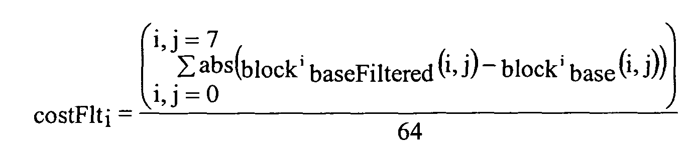
- costFlti a cost of filtering by means, for example, of the following formula: where abs is the absolute value function, and block basefiltered (i,j) - block base (i,j) represents the difference in quality at the level of the block comprising the pixel with coordinates i and j, belonging to the decoded image (of the base layer) after filtering and before filtering intended to reduce the block effects.
- NbBitsfgs i throughput fgs ⁇ costF1t i COSTF1t
- a significant coding of the enhancement layer of a pixel block is also favoured if this block is situated in a zone of an image where the luminance is low. In fact, the anomalies of an image are more visible in the dark zones of this image.
- the average luminance of each block is calculated in such a way that the blocks whose average luminance is lower benefit from increased coding in the enhancement layer.
- This average luminance Lavg can be calculated by: k and l being the coordinates of the pixels contained in the block i.
- F(Lavg i ) being a weighting function which varies between 0.5 and 1.
- this weighting function F(Lavg i ) may be kept constant, for example equal to 1/2, this approach making it possible to favour the blocks with low luminance vis-à-vis those with high luminance.
- Thresh Lum exhibits a maximum luminance (255).
- a significant coding of the enhancement layer of a pixel block is also favoured if this block is situated in a zone of an image where the texture is weak since a restitution defect located in a weakly textured zone is more visible than in a zone with strong texture.
- this texture is measured by an activity Act i inside the block i evaluated for example, as follows: k and l being the coordinates of the pixels contained in the block, b i,src being a block of index i of the source image and max(a-b) being equal to a if a is greater than b or equal to b otherwise.
- F(Lavg i ) being a weighting function which varies between 0.5 and 1 in a similar manner to the weighting function described above.
- the weighting coefficient F(Act i ) can be kept constant, for example equal to 1/2, thus making it possible to favour the blocks with weak texture vis-à-vis blocks with strong texture.
- NbBitsfgs i throughput fgs ⁇ costF1t i * F(Act i ) * F(Lavg i ) COSTF1t
- the amplitude of the motion vector associated with a block of pixels can also be taken into account when considering the quantity of bits allotted to this block of pixels in the enhancement layer.
- the zone of the image coded by this block may be considered to correspond to an element moving in the image and for which a lesser resolution than for the still zones of the image may be satisfactory.
- Application on the basis of the block effect measured on completion of the post-filtering can be effected by calculating a filtering cost, relating to the image, weighted with the amplitude of the vectors, for example by means of the following formula:
- NbBitsfgs i throughput fgs ⁇ costF1t i * F(Vect i ) COSTF1t
- F(Vect i ) being a weighting function which varies between 0 and 1.
- this function F(Vect i ) equals: 1- (Vect i / Thresh Vect )
- any block whose displacement vector has a norm that is less than a threshold Thresh Vect will be enhanced as a function of a cost and of its displacement whereas, if the vector is beyond a threshold, this block will have no additional enhancement layer.
- the value of the threshold is dependent, among other things, on the resolution of the image, a value of 30 giving acceptable results for an image in the CIF format (288 lines of 352 pixels).
- the position of a current block is estimated at the next image on the basis of the displacement vector of this block, for example by adding the components Vx and Vy of the vector Vect(Vx, Vy) respectively to the central coordinates of the block ib and jb.
- the number of bits in the enhancement layer can vary as a function of these parameters.
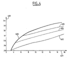
- FIG. 4 is shown a fan of curves 402, 404 and 406 identifying a quality of restitution (ordinate axis 401, in dB), as a function of a number of bits allotted for a block (abscissa axis 403).
- Each curve corresponds to a transmission of an image by means of a base layer (respectively at 192, 256 and 384 kbits/s) associated with an enhancement layer of increasing size.
- This fan is generated from a curve 400 which represents the restitution quality/number of bits per block ratio when a single base layer is transmitted.
- the transmission of a single base layer is more efficacious than the transmission of a base layer associated with an enhancement layer, this conveying the greater efficiency of the coding of the base layer with respect to the coding of the enhancement layer.
- This technique can take into consideration the combination of weighting parameters of two or more of the already described parameters relating to the block currently being coded, namely block effects, a filtering cost, the local average luminance, the local activity, an amplitude of the motion vector and/or a risk of exiting the scene in the next image.
- the position and/or the function of the image to which a pixel block belongs can also be a parameter considered in determining the quantity of bits of the enhancement layer allotted to a block.
- an image is used to generate other images, as in the particular case of a predictive coding scheme where an inter-image uses images reconstructed with the aid of their base layer and of all or part of their enhancement layer, the blocks of this image are processed with a lower enhancement layer if these blocks belong to an isolated image or to one situated at the end of a series of images.
Landscapes
- Engineering & Computer Science (AREA)
- Multimedia (AREA)
- Signal Processing (AREA)
- Compression Or Coding Systems Of Tv Signals (AREA)
- Compression Of Band Width Or Redundancy In Fax (AREA)
- Compression, Expansion, Code Conversion, And Decoders (AREA)
Abstract
Description
- The present invention pertains to a device and to a method for compressing digital images.
- The compression of a digital image reduces the quantity of data necessary for its transmission via, for example, a telecommunication network such as the Internet network.
- Certain compression standards, such as the MPEG-4 standard (Motion Picture Expert Group 4), use a so-called multilayer compression according to which an image, the so-called source image, is compressed by means of a base layer, coding a so-called base image, and of an enhancement layer, coding the deviation or the residual, between the source image and the base image.
- In this case, the transmission of a compressed image can be done by transmitting, firstly, its base layer and then, secondly, its enhancement layer, in the form of binary trains.
- The binary train associated with the enhancement layer has the advantage of being able to be truncated in such a way that, if transmission thereof is performed only partially following, for example, a variation in the transmission throughput in the network, the information transmitted in the correctly received part of the binary train may nevertheless still be used to enhance the image coded by the base layer.
- To do this, a residual 101 (Figure 1), coding enhancement coefficients 1011, 1012, ...101n specific to each block of pixels forming the image, is decomposed into various planes MSB, MSB-1, MSB-2, MSB-3 and LSB of bits ranked in order of priority, each plane MSB, MSB-1, MSB-2, MSB-3 or LSB clustering together bits of like weight in the decomposition of the residual specific to each block.
- As described later, these coefficients 1011, 1012, ...101n may arise from the discrete cosine transformation DCT of an 8x*8 block of pixels, performed by evaluating the difference between the DCT coefficients of a block of a source image, that is to say of the coded image, and the DCT coefficients of an image processed by a quantization and then by an inverse quantization of its base layer.
- By generating a binary train 130 successively transmitting the planes MSB, MSB-1, MSB-2, MSB-3 or LSB, one then obtains an enhancement layer which can be truncated without compromising the transmission of the train as a whole. For example, if the transmission of the train 130 is disturbed during the transmission of the plane MSB-3, the information as a whole already transmitted by the planes MSB, MSB-1, MSB-2 and the transmitted part of MSB-3 will be able to be taken into account to enhance the image.
- Such a method, dubbed Fine Granularity Scalability (Fgs) within the framework of the MPEG4 standard, has the drawback of using a compression of the residual having an efficiency lower than the efficiency of the compression of the base code. In this way, a compromise between the efficiency of the compression, increased by a base layer of significant size, and the security of the transmission of the base, increased with a base layer of small size, may possibly be made.
- The present invention remedies this drawback. It pertains to a device for compressing a source image by means of a base layer, coding a base image, and of an enhancement layer, coding a residual existing between the source image and the base image, the source image and the base image being structured as blocks of pixels, characterized in that it comprises means for generating the enhancement layer of a block as a function of the quality of restitution of this block, determined by comparing the coding of this block in the source image with the coding of this block in the base image, and/or as a function of information coded by this block of pixels.
- By considering the quality of restitution of the image on the basis of the base layer blockwise, the device in accordance with the invention makes it possible to optimize the generation of the enhancement layer by assigning each block a quantity of bits in the enhancement layer dependent on the base coding of this block so that the final image has a uniform quality of restitution.
- Moreover, by taking into account the information relating to the coding of each block, the device in accordance with the invention optimizes the generation of the base layer by allotting more data to blocks of pixels for which an enhancement of the base layer results priority-wise, for example if resolution defects associated with this block are more visible than for other blocks.
- In one embodiment, the device comprises means for determining the quality of restitution of the block (k) by means of a formula such as:where (i,j) represents the coordinates of a pixel of the block (k) considered, for example of dimensions 8x8, in the source image (blocksource) or in the base image (block,rec) coded by the base layer, L representing the value of the maximum luminance of the image, for example equal to 255.

- According to one embodiment, the device comprises means for defining an average quality Psnravg of restitution of the image and for allocating a greater number of bits in the enhancement layer to the blocks whose restitution quality is less than this average quality Pnsravg or than a reference quality Pnsrref obtained on the basis of this average quality, for example by adding a quality margin.
- In one embodiment, the device comprises means for comparing the quality psnrk of restitution of the block k with a reference quality psnrref in such a way as to detect a deviation δpsnrk of quality with respect to this reference psnrref and means for allotting a number NbBitsk of bits of the enhancement layer to this block as a function of this deviation.
- According to one embodiment, the device comprises means for allotting a number NbBitsk of bits of the enhancement layer by using a proportionality relation such as:
- In one embodiment, the sum Δpsnr is evaluated on the basis of the deviations between the quality of each block and the reference quality, for example by means of a formula such as:where M and N are parameters relating to the index number of each block in the image, a block being considered only if its quality psnrk of restitution is less than the reference quality of restitution (psnrk < psnrref).

- According to one embodiment, the device comprises means for estimating the quality of restitution of the base layer by estimating the degradation, or the cost CostFlti, of its filtering intended to reduce contrasts between neighbouring blocks and means for allotting to a block (k) of pixels a bigger number NbBitsk of bits of the enhancement layer the higher this cost CostFlti.
- In one embodiment, the device comprises means for estimating the cost CostFlti of the filtering with the aid of a formula such as:where abs is the absolute value function, and blockbasefiltered(i,j) - blockbase(i,j) represents the difference in values of the pixel with coordinates i and j of the base layer after filtering and before filtering.
- According to one embodiment, the device comprises means for comparing the cost of filtering costFlti of a block with a cost of filtering of the image COSTFlt and means for allotting a number NbBitsfgsi of bits of the enhancement layer to each block i as a function of this comparison, for example by using a relation such as:
where throughputfgs is the quantity of bits per image contained in the train of the enhancement layer. - In one embodiment, the device comprises means for determining the cost costFlt of filtering of the image by adding up the costs of filtering of all the blocks of the image, for example with the aid of a formula such as:where i represents a block index number whilst M and N represent the dimensions of the image.
- According to one embodiment, the device comprises means for generating the enhancement layer of a block as a function of a parameter relating to an average luminance (Lavg) associated with this block, determined for example by adding up the luminances of the pixels of the block considered.
- In one embodiment, the device comprises means for weighting the cost of the filtering of a block as a function of a coefficient F(Lavgi) whose value depends on the average luminance of this block.
- According to one embodiment, the device comprises means such that, if the average luminance Lavgi of a block is greater than a threshold, ThreshLum, then the value of this weighting coefficient is calculated according to the formula:
- In one embodiment, the device comprises means for weighting the cost of the filtering as a function of a coefficient F(Lavgi) whose value depends on the texture, or activity, of the considered block of pixels.
- According to one embodiment, the device comprises means such that the activity Acti of a block i is calculated by means of a formula such as:where k and l are the coordinates of the pixels contained in a block, bi,src being a block of index i of the source image and max (a,b) is equal to a when a is greater than b, and equals b otherwise.

- In one embodiment, the device comprises means such that the cost of the filtering of a block is weighted by means of a factor (F(Acti)) dependent on its activity.
- In one embodiment, the device comprises means such that the weighting factor F(Acti) varies between 0.5 and 1 as a function of a threshold ThreshAct such that, if the activity Acti of the block i considered is less than this threshold ThreshAct then the coefficient F(Acti) is equal to:
- According to one embodiment, the device comprises means for generating the enhancement layer by considering a motion or displacement vector associated with each pixel block i, for example by means of the formula:
- According to one embodiment, the device comprises means such that the cost of the filtering of a block is weighted by means of a factor F(Vecti) dependent on the motion vector of this block.
- In one embodiment, the device comprises means such that the weighting factor F(Vecti) varies between 0 and 1 as a function of a motion threshold ThreshVect, for example such that if the norm of the vector Vecti is less than this threshold ThreshVect, then this factor equals:
- According to one embodiment, the device comprises means for generating the enhancement layer by considering the possible exit of the block in an image subsequent to the image considered.
- In one embodiment, the device comprises means for anticipating the exit of the block from the image by adding the components Vx and Vy of the displacement vector Vect of this block ibnext = ib + Vx and jbnext = jb + Vy to the coordinates ib and jb of this block, in such a way that if the estimated position of the block at the next image is outside the image (ibnext <0) or (ibnext >M) or (jbnext <0) or (jbnext >N), M and N being the dimensions of the image, the enhancement layer of this block is not processed.
- In one embodiment, the device comprises means for estimating the quality psnr of restitution of a block of pixels with the aid of an affine modelling such that the quality psnr of restitution of an image has a linear form:
- According to one embodiment, the device comprises means for generating the enhancement layer by allotting more bits to the blocks of an image if this image is used to generate other images, for example in the case of an inter-image predictive coding.
- In one embodiment, the device comprises means for coding the base layer with the aid of a discrete cosine transform.
- The invention also relates to a method for compressing a source image by means of a base layer, coding a base image, and of an enhancement layer, coding a residual existing between the source image and the base image, the source image and the base image being structured as blocks of pixels, characterized in that a device is used which generates the enhancement layer of a block as a function of a quality of restitution of this block, in accordance with one of the preceding claims.
- Other characteristics and advantages of the invention will become apparent with the description of the invention given hereinbelow, by way of nonlimiting example, while referring to the appended figures in which:
- Figure 1, already described, represents a method of coding an enhancement layer according to a known method,
- Figure 2 ,is a diagram of a compressor of images coded according to a multilayer method in accordance with the graphical invention,
- Figure 3 represents a distribution of variable restitution qualities for various blocks of one and the same image, and
- Figure 4 represents variations of efficiency during a multilayer coding.
- A coder 210 (Figure 2) in accordance with the invention can comprise a receiver 211 receiving a signal 212 which codes an image to be compressed. Within the framework of coding in inter-image modes, this receiver 211 subtracts from this signal 212 information already transmitted for a previous image. This operation is performed with the aid of a subtractor 214 which receives a signal 234 corresponding to the information transmitted for the previous images.
- Thus, the signal 212 is transformed into a signal 21614, which is directed to a transformer 218 which transforms the signal 21614, defined in the spatial domain, into a signal 21618 defined in the frequency domain. This operation, which is performed with no loss of information, is a discrete cosine transform or DCT.
- The signals 21618 are transmitted to a quantizer 220 which reduces the dynamic swing of these signals via a quantization operation which involves approximations entailing a non-negligible loss of information of the signal 21618.
- The information thus lost during this quantization operation is called the residual (residual information intended for the fgs coder), whereas the information retained after quantization constitutes the base layer of the compressed image.
- Stated otherwise, the base layer comprises the data received by the coder minus this residual, the latter being coded by the enhancement layer as described later.
- On exit from the quantizer 220, the signal 21620 is also transmitted to a subtraction loop which comprises an inverse quantizer 224 performing the inverse function of the quantizer 220. This inverse quantization operation is performed without any new loss of information.
- One then obtains a signal 21624 which is applied to a converter 226 performing the inverse function (IDCT) to that carried out by the transformer 218, that is to say converting this signal 21624 from the frequency domain to the spatial domain, thus outputting a signal 21626 which is transmitted to a memory 228 and a motion estimation/compensation processor 230 then to the subtractor 214.
- The signal 21624 is also transmitted to a subtractor 236, forming part of a branch 235 for generating the enhancement layer, a second input of the subtractor 236 receiving the output signal 21618 from the DCT transformer 218.
- Thus, this subtractor 236 performs the subtraction between signals representing the signals received 21618 and sent 21624 so as to obtain the residual 21636 on output from the subtractor 236.
- The branch 235 comprises a memory 238 which stores the residuals (in the spatial frequency domain) imagewise and a device 240 which performs the partition into enhancement planes of the signal 21638 on exit from the memory 238 according to the standardized method known as "Fine granularity scalability" (FGS) already described.
- Furthermore, the branch 235 comprises means 250 for analysing the blocks of pixels compressed in such a way as to determine their quality of restitution, on the basis of the base layer, and for determining, as a function of this quality and of information relating to the coding of the pixels of a block considered, what quantity of bits should be allotted to this block at the enhancement layer level.
- In this embodiment of the invention, the quality or "psnrk" of restitution is measured, for a block k of pixels, by means of the following formula:where (i,j) represents the coordinates of a pixel of the block considered, for example of dimensions 8x8, in the source image (blocksource) or in the reconstructed base image (block,rec) coded by the base layer.

- By means of the quality of restitution psnrk calculated for each block k of pixels, it is possible to calculate the average quality of restitution psnravg of the image, for example by averaging the qualities psnr of restitution of each of the blocks of the image or by using a graphical procedure as described later.
- Finally, a reference restitution quality psnravg specific to the image is obtained on the basis of the average quality Psnravg to which is added a margin, for example, of 3 dB.
- Thereupon, each measurement of restitution quality psnrk is compared with the reference psnrref to detect a possible defect δpsnrk of quality of restitution, that is to say a deficit in terms of quality of restitution with respect to the threshold psnrref defined.
- As a function of this possible deficit δpsnrk in terms of quality of restitution, one allots a certain number NbBitsk of bits on the train of the enhancement layer by using a proportionality relation such as:where M and N are parameters relating to the index number of each block in the image, a block being considered only if its quality psnrk of restitution is less than the reference quality of restitution (psnrk < psnrref).

- Such an operation is illustrated with the aid of Figure 3 which represents blocks 343, identified by their block index number (abscissa axis 302) and for which the quality psnrk of restitution (ordinate axis 304) has been determined in accordance with the formula indicated above.
- A reference quality psnrref 342 is defined on the basis of an average quality of restitution 340 and of a predetermined quality margin 341.
- In accordance with the invention, no coding is performed in the enhancement layer for blocks 343i whose quality of restitution is greater than the reference threshold whereas an enhancement coding is performed for the blocks of pixels whose restitution quality is less than the reference quality (psnrref), a bigger number of bits being allotted to this coding the higher this deviation.
- Another enhancement layer generation parameter taken into account by the means 250 (Figure 2) is the variation of the information in a block after its filtering intended to reduce any block effects, that is to say the problems of contrast existing between two neighbouring pixel blocks.
- For this purpose, it is appropriate to recall that such a filtering is performed at the base layer level in an optional manner at the decoder level in the case of the MPEG4 standard.
- Nevertheless, this post-filtering can be carried out at the coder level so as to estimate the rendition on the reconstructed image of the base layer vis-à-vis the source image.
- In the latter case, the post-filtering does not intervene in the loop of the inter-image coding process which then serves only to estimate the degradation between the decoded image (of the base layer) and the source image.
- On the other hand, if a filter is present in this loop, the degradation estimation operation can be carried out therein. Such is the case within the framework of the h263, h261 and MPEF-4 part 10 standards.
- To do this, one can evaluate a cost (costFlti) of filtering by means, for example, of the following formula:where abs is the absolute value function, and blockbasefiltered(i,j) - blockbase(i,j) represents the difference in quality at the level of the block comprising the pixel with coordinates i and j, belonging to the decoded image (of the base layer) after filtering and before filtering intended to reduce the block effects.

- On the basis of the cost of the filtering of a block of pixels it is possible to calculate a total cost COSTFlt for the image by summing the costFlti specific to each block such that:

- Finally, it is possible to determine the number of bits to be allotted in the data train of the enhancement layer to a block as a function of the following formula:
- In this embodiment, a significant coding of the enhancement layer of a pixel block is also favoured if this block is situated in a zone of an image where the luminance is low. In fact, the anomalies of an image are more visible in the dark zones of this image.
- For this purpose, the average luminance of each block is calculated in such a way that the blocks whose average luminance is lower benefit from increased coding in the enhancement layer.
This average luminance Lavg can be calculated by:k and l being the coordinates of the pixels contained in the block i.
- Application on the basis of the block effect (post-filtering) measured on completion of the post-filtering can be effected in the following manner:
- The calculation of the filtering cost, relating to the
image, weighted with local average luminance
- The distribution of the number of bits per block then
becomes:
-
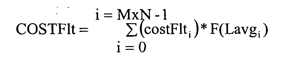
- F(Lavgi) being a weighting function which varies between 0.5 and 1. In this embodiment, if the luminosity Lavgi of a block i is less than a threshold ThreshLum (Lavgi < ThreshLum), then this function may be written: F(Lavgi) = 1-( Lavgi / 2xThreshLum).
- Otherwise, this weighting function F(Lavgi) may be kept constant, for example equal to 1/2, this approach making it possible to favour the blocks with low luminance vis-à-vis those with high luminance.
- It is appropriate to note that the threshold value ThreshLum exhibits a maximum luminance (255).
- In this embodiment, a significant coding of the enhancement layer of a pixel block is also favoured if this block is situated in a zone of an image where the texture is weak since a restitution defect located in a weakly textured zone is more visible than in a zone with strong texture.
- For this purpose, this texture is measured by an activity Acti inside the block i evaluated for example, as follows:k and l being the coordinates of the pixels contained in the block, bi,src being a block of index i of the source image and max(a-b) being equal to a if a is greater than b or equal to b otherwise.

- Application on the basis of the block effect measured on completion of the post-filtering may then be effected by calculating the cost of the filtering, relating to the image, weighted with the local activity determined as indicated above:The blockwise distribution of the number of bits then becomes:

- F(Lavgi) being a weighting function which varies between 0.5 and 1 in a similar manner to the weighting function described above. In this example, if the activity Acti is less than a given threshold ThreshAct, then this weighting coefficient F(Acti) is determined by the following formula:
- Otherwise, the weighting coefficient F(Acti) can be kept constant, for example equal to 1/2, thus making it possible to favour the blocks with weak texture vis-à-vis blocks with strong texture.
- Furthermore, it is appropriate to note that the texture exhibits a maximum threshold value (ThreshAct = 255).
- The combination of the two criteria based on the average luminance and the activity that are contained in the block can be effected, the spread of the information dedicated to the improvement layer then becomes:

- The blockwise distribution being evaluated by means of a formula such as:
- The amplitude of the motion vector associated with a block of pixels can also be taken into account when considering the quantity of bits allotted to this block of pixels in the enhancement layer.
- This approach makes it possible to exploit the effect of masking through motion of the restitution defects inherent in the image coding, and in particular at low and very low throughput.
- In fact, if a block of pixels is associated with a significant motion vector, then the zone of the image coded by this block may be considered to correspond to an element moving in the image and for which a lesser resolution than for the still zones of the image may be satisfactory.
- The determination of the modulus of the motion vector Vecti associated with a block i is determined by means of a formula such as:
- Application on the basis of the block effect measured on completion of the post-filtering can be effected by calculating a filtering cost, relating to the image, weighted with the amplitude of the vectors, for example by means of the following formula:
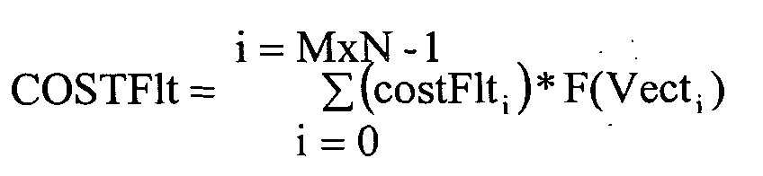
- The distribution of the number of bits allotted per block then becomes:
- F(Vecti) being a weighting function which varies between 0 and 1. In this example, if the norm of the motion vector Vecti of a block i is less than a threshold ThreshVect, then this function F(Vecti) equals:
- Otherwise, if the norm of this vector is greater than this threshold, this function is zero (F(Vecti) = 0).
- Thus any block whose displacement vector has a norm that is less than a threshold ThreshVect will be enhanced as a function of a cost and of its displacement whereas, if the vector is beyond a threshold, this block will have no additional enhancement layer.
- It is appropriate to note that the value of the threshold is dependent, among other things, on the resolution of the image, a value of 30 giving acceptable results for an image in the CIF format (288 lines of 352 pixels).
- Similarly, if a block of pixels that is situated at the border of the image is associated with a motion vector such that it is possible to anticipate that the zone of the coded image to which this block belongs will exit this image in the future, it is unnecessary to code this zone with a high resolution.
- Hence, the position of a current block is estimated at the next image on the basis of the displacement vector of this block, for example by adding the components Vx and Vy of the vector Vect(Vx, Vy) respectively to the central coordinates of the block ib and jb.
- Stated otherwise, if the central coordinates of the current block are ib and jb, the current block's central coordinates estimated at the next image are:
- Thus, if the estimation of the coordinates for the next image exits the framework of the image ((ibnext <0) or (ibnext >M) or (jbnext <0) or (jbnext >N)), where M and N represent the dimensions of the image to be processed, then the block is not enhanced.
- In accordance with the invention, various parameters have been described hereinabove which make it possible to determine a number of bits, that is allotted to a block of pixels, as a function of information coded in these blocks, such as a motion vector or significant contrasts, and/or of the quality of restitution of the image using the base layer.
- Therefore, it is apparent that the number of bits in the enhancement layer can vary as a function of these parameters.
- In order to control such variations, in one embodiment of the invention, use is made of models of variations of quality of restitution of an image to determine what quality of restitution is attained by the transmission of a base layer and of a variable enhancement layer, as explained hereinbelow with the aid of Figure 4.
- In this Figure 4 is shown a fan of curves 402, 404 and 406 identifying a quality of restitution (ordinate axis 401, in dB), as a function of a number of bits allotted for a block (abscissa axis 403).
- Each curve (respectively 402, 404 and 406) corresponds to a transmission of an image by means of a base layer (respectively at 192, 256 and 384 kbits/s) associated with an enhancement layer of increasing size.
- This fan is generated from a curve 400 which represents the restitution quality/number of bits per block ratio when a single base layer is transmitted.
- It is thus noted that, for one and the same quality, the transmission of a single base layer is more efficacious than the transmission of a base layer associated with an enhancement layer, this conveying the greater efficiency of the coding of the base layer with respect to the coding of the enhancement layer.
- One also observes that the fan of curves 402, 404 and 406 exhibits an almost affine form such that the quality psnr of restitution of an image takes a form
- It should be noted that this constant Dpsnr, which makes it possible to approximate the variation of restitution quality/throughput fgs, corresponds to a type of algorithm making it possible to undertake compression of fine scalability type.
- However, it is also appropriate to note that this constant is dependent on the compression algorithm implemented.
- Thereupon, it is possible to determine simply the number of bits that have to be allocated to an image, or to each block of this image, to obtain a given quality of restitution.
- In fact, by fixing a determined quality psnrdet of restitution, it is possible to estimate the number of bits per block that have to be allotted to a block in the enhancement layer by calculating the deviation between the number of bits per block transmitted in the base layer (curve 400) and the number of bits per block that have to be transmitted to obtain the required quality of restitution.
- Such a procedure for the graphical determination of the number of bits that have to be allotted in the enhancement layer to obtain a given quality of restitution is particularly simple since it requires a limited calculation capacity.
- Moreover, it makes it possible to limit the number of bits that is allotted in the enhancement layer to a block of pixels by again optimizing the efficiency of the coding of this layer since it makes it possible to avoid overcoding a block by determining, in a required compression quality context, whether the restitution quality thereof has already attained the required quality.
- This technique can take into consideration the combination of weighting parameters of two or more of the already described parameters relating to the block currently being coded, namely block effects, a filtering cost, the local average luminance, the local activity, an amplitude of the motion vector and/or a risk of exiting the scene in the next image.
- The present invention is open to numerous variants. Thus, the position and/or the function of the image to which a pixel block belongs can also be a parameter considered in determining the quantity of bits of the enhancement layer allotted to a block.
- In fact, if an image is used to generate other images, as in the particular case of a predictive coding scheme where an inter-image uses images reconstructed with the aid of their base layer and of all or part of their enhancement layer, the blocks of this image are processed with a lower enhancement layer if these blocks belong to an isolated image or to one situated at the end of a series of images.
Claims (16)
- Device (210) for compressing a source image by means of a base layer, coding a base image, and of an enhancement layer, coding a residual existing between the source image and the base image, the source image and the base image being structured as blocks of pixels, characterized in that it comprises means (250) for generating the enhancement layer of a block (k) as a function of the quality (psnrk) of restitution of this block (k), determined by comparing the coding of this block in the source image with the coding of this block in the base image, and/or as a function of information coded by this block of pixels.
- Device according to Claim 1, characterized in that it comprises means for determining the quality (psnrk) of restitution of the block (k) by means of a formula such as:where (i,j) represents the coordinates of a pixel of the block (k) considered, for example of dimensions 8x8, in the source image (blocksource) or in the base image (block,rec) coded by the base layer, L representing the value of the maximum luminance of the image, for example equal to 255.

- Device according to Claim 1, characterized in that it comprises means for defining an average quality (Psnravg) of restitution of the image and for allocating a greater number of bits in the enhancement layer to the blocks whose restitution quality is less than this average quality (Pnsravg) or than a reference quality (Pnsrref) obtained on the basis of this average quality, for example by adding a quality margin.
- Device according to claim 1, characterized in that it comprises means for comparing the quality (psnrk) of restitution of the block k with a reference quality (psnrref) in such a way as to detect a deviation (δpsnrk) of quality with respect to this reference (psnrref) and means for allotting a number (NbBitsk) of bits of the enhancement layer to this block as a function of this deviation.
- Device according to Claim 4, characterized in that it comprises means for allotting a number (NbBitsk) of bits of the enhancement layer by using a proportionality relation such as:
- Device according to claim 1, characterized in that it comprises means for estimating the quality of restitution of the base layer by estimating the degradation, or the cost (CostFlti), of its filtering intended to reduce contrasts between neighbouring blocks and means for allotting to a block (k) of pixels a bigger number (NbBitsk) of bits of the enhancement layer the higher this cost (CostFlti).
- Device according to Claim 6, characterized in that it comprises means for estimating the cost (CostFlti) of the filtering with the aid of a formula such as:where abs is the absolute value function, and blockbasefiltered(i,j) - blockbase(i,j) represents the difference in values of the pixel with coordinates i and j of the base layer after filtering and before filtering.

- Device according to Claim 6, characterized in that it comprises means for generating the enhancement layer of a block as a function of a parameter relating to an average luminance (Lavg) associated with this block, determined for example by adding up the luminances of the pixels of the block considered.
- Device according to claim 8, characterized in that it comprises means for weighting the cost of the filtering of a block as a function of a coefficient F(Lavgi) whose value depends on the average luminance of this block.
- Device according to claim 6, characterized in that it comprises means for weighting the cost of the filtering as a function of a coefficient F(Lavgi) whose value depends on the texture, or activity, of the considered block of pixels.
- Device according to claim 1, characterized in that it comprises means for generating the enhancement layer by considering a motion or displacement vector associated with each pixel block i, for example by means of the formula:
- Device according to claim 1, characterized in that it comprises means for generating the enhancement layer by considering the possible exit of the block in an image subsequent to the image considered.
- Device according to claim 1, characterized in that it comprises means for estimating the quality (psnr) of restitution of a block of pixels with the aid of an affine modelling such that the quality (psnr) of restitution of an image has a linear form:
- Device according to claim 1, characterized in that it comprises means for generating the enhancement layer by allotting more bits to the blocks of an image if this image is used to generate other images, for example in the case of an inter-image predictive coding.
- Device according to claim 1, characterized in that it comprises means for coding the base layer with the aid of a discrete cosine transform (DCT).
- Method for compressing a source image by means of a base layer, coding a base image, and of an enhancement layer, coding a residual existing between the source image and the base image, the source image and the base image being structured as blocks of pixels, characterized in that the enhancement layer of a block is generated as a function of the quality (psnrk) of restitution of this block (k), determined by comparing the coding of this block in the source image with the coding of this block in the base image, and/or as a function of information coded by this block of pixels.
Applications Claiming Priority (2)
| Application Number | Priority Date | Filing Date | Title |
|---|---|---|---|
| FR0309713 | 2003-08-07 | ||
| FR0309713A FR2858741A1 (en) | 2003-08-07 | 2003-08-07 | DEVICE AND METHOD FOR COMPRESSING DIGITAL IMAGES |
Publications (2)
| Publication Number | Publication Date |
|---|---|
| EP1505837A1 true EP1505837A1 (en) | 2005-02-09 |
| EP1505837B1 EP1505837B1 (en) | 2018-04-04 |
Family
ID=33548317
Family Applications (1)
| Application Number | Title | Priority Date | Filing Date |
|---|---|---|---|
| EP04077277.4A Expired - Lifetime EP1505837B1 (en) | 2003-08-07 | 2004-07-30 | Device and method for compressing digital images |
Country Status (7)
| Country | Link |
|---|---|
| US (1) | US9031332B2 (en) |
| EP (1) | EP1505837B1 (en) |
| JP (1) | JP4806172B2 (en) |
| KR (1) | KR20050016203A (en) |
| CN (1) | CN1581979A (en) |
| FR (1) | FR2858741A1 (en) |
| TW (1) | TW200511831A (en) |
Cited By (1)
| Publication number | Priority date | Publication date | Assignee | Title |
|---|---|---|---|---|
| WO2007038807A3 (en) * | 2005-09-29 | 2007-06-07 | Thomson Res Funding Corp | Method and apparatus for constrained variable bit rate (vbr) video encoding |
Families Citing this family (11)
| Publication number | Priority date | Publication date | Assignee | Title |
|---|---|---|---|---|
| US8131095B2 (en) * | 2003-02-03 | 2012-03-06 | Actimagine | Process and device for the compression of portions of images |
| KR100746007B1 (en) | 2005-04-19 | 2007-08-06 | 삼성전자주식회사 | Method and apparatus for adaptively selecting context model of entrophy coding |
| KR100763181B1 (en) | 2005-04-19 | 2007-10-05 | 삼성전자주식회사 | Method and apparatus for improving coding rate by coding prediction information from base layer and enhancement layer |
| FI3703369T3 (en) | 2010-04-13 | 2024-10-29 | Ge Video Compression Llc | Sample region merging |
| CN106028045B (en) * | 2010-04-13 | 2019-06-25 | Ge视频压缩有限责任公司 | Method for decoding data stream, method for generating data stream and decoder thereof |
| KR101792967B1 (en) | 2010-04-13 | 2017-11-02 | 지이 비디오 컴프레션, 엘엘씨 | Inheritance in sample array multitree subdivision |
| CN106231325B (en) | 2010-04-13 | 2020-02-04 | Ge视频压缩有限责任公司 | Decoder, decoding method, encoder, and encoding method |
| WO2011127966A1 (en) | 2010-04-13 | 2011-10-20 | Fraunhofer-Gesellschaft zur Förderung der angewandten Forschung e.V. | Inter-plane prediction |
| GB2496862B (en) * | 2011-11-22 | 2016-06-01 | Canon Kk | Communication of data blocks over a communication system |
| US11221990B2 (en) | 2015-04-03 | 2022-01-11 | The Mitre Corporation | Ultra-high compression of images based on deep learning |
| US10607108B2 (en) * | 2018-04-30 | 2020-03-31 | International Business Machines Corporation | Techniques for example-based affine registration |
Citations (1)
| Publication number | Priority date | Publication date | Assignee | Title |
|---|---|---|---|---|
| WO2003036980A1 (en) * | 2001-10-26 | 2003-05-01 | Koninklijke Philips Electronics N.V. | Spatial scalable compression scheme using spatial sharpness enhancement techniques |
Family Cites Families (9)
| Publication number | Priority date | Publication date | Assignee | Title |
|---|---|---|---|---|
| GB2317525B (en) * | 1996-09-20 | 2000-11-08 | Nokia Mobile Phones Ltd | A video coding system |
| JP4034380B2 (en) * | 1996-10-31 | 2008-01-16 | 株式会社東芝 | Image encoding / decoding method and apparatus |
| US6501797B1 (en) * | 1999-07-06 | 2002-12-31 | Koninklijke Phillips Electronics N.V. | System and method for improved fine granular scalable video using base layer coding information |
| JP2000341692A (en) | 2000-01-01 | 2000-12-08 | Sony Corp | Encoding device and method |
| US6907070B2 (en) * | 2000-12-15 | 2005-06-14 | Microsoft Corporation | Drifting reduction and macroblock-based control in progressive fine granularity scalable video coding |
| US6792044B2 (en) * | 2001-05-16 | 2004-09-14 | Koninklijke Philips Electronics N.V. | Method of and system for activity-based frequency weighting for FGS enhancement layers |
| US6785334B2 (en) | 2001-08-15 | 2004-08-31 | Koninklijke Philips Electronics N.V. | Method for transmission control in hybrid temporal-SNR fine granular video coding |
| FR2833796B1 (en) * | 2001-12-19 | 2004-04-09 | Thomson Licensing Sa | METHOD AND DEVICE FOR COMPRESSING VIDEO DATA ENCODED BY VIDEO PACKETS |
| US6996172B2 (en) * | 2001-12-21 | 2006-02-07 | Motorola, Inc. | Method and structure for scalability type selection in digital video |
-
2003
- 2003-08-07 FR FR0309713A patent/FR2858741A1/en active Pending
-
2004
- 2004-07-30 EP EP04077277.4A patent/EP1505837B1/en not_active Expired - Lifetime
- 2004-08-03 CN CNA200410055920XA patent/CN1581979A/en active Pending
- 2004-08-06 US US10/912,833 patent/US9031332B2/en active Active
- 2004-08-06 TW TW093123563A patent/TW200511831A/en unknown
- 2004-08-06 KR KR1020040062035A patent/KR20050016203A/en not_active Ceased
- 2004-08-09 JP JP2004232765A patent/JP4806172B2/en not_active Expired - Lifetime
Patent Citations (1)
| Publication number | Priority date | Publication date | Assignee | Title |
|---|---|---|---|---|
| WO2003036980A1 (en) * | 2001-10-26 | 2003-05-01 | Koninklijke Philips Electronics N.V. | Spatial scalable compression scheme using spatial sharpness enhancement techniques |
Non-Patent Citations (4)
| Title |
|---|
| "N3317 - FGS Verification Model - Version 4.0 - Draft of 11 April 2000", ISO/IEC JTC1/SC29/WG11 N3317, XX, XX, March 2000 (2000-03-01), pages 1 - 35, XP000926359 * |
| LI W: "OVERVIEW OF FINE GRANULARITY SCALABILITY IN MPEG-4 VIDEO STANDARD", IEEE TRANSACTIONS ON CIRCUITS AND SYSTEMS FOR VIDEO TECHNOLOGY, IEEE INC. NEW YORK, US, vol. 11, no. 3, March 2001 (2001-03-01), pages 301 - 317, XP000994715, ISSN: 1051-8215 * |
| LIN E ET AL: "A hybrid embedded video codec using base layer information for enhancement layer coding", PROCEEDINGS 2001 INTERNATIONAL CONFERENCE ON IMAGE PROCESSING. ICIP 2001. THESSALONIKI, GREECE, OCT. 7 - 10, 2001, INTERNATIONAL CONFERENCE ON IMAGE PROCESSING, NEW YORK, NY: IEEE, US, vol. 1 OF 3. CONF. 8, 7 October 2001 (2001-10-07), pages 1005 - 1008, XP010563936, ISBN: 0-7803-6725-1 * |
| VAN DER SCHAAR M ET AL: "Content-based selective enhancement for streaming video", PROCEEDINGS 2001 INTERNATIONAL CONFERENCE ON IMAGE PROCESSING. ICIP 2001. THESSALONIKI, GREECE, OCT. 7 - 10, 2001, INTERNATIONAL CONFERENCE ON IMAGE PROCESSING, NEW YORK, NY: IEEE, US, vol. 1 OF 3. CONF. 8, 7 October 2001 (2001-10-07), pages 977 - 980, XP010563929, ISBN: 0-7803-6725-1 * |
Cited By (2)
| Publication number | Priority date | Publication date | Assignee | Title |
|---|---|---|---|---|
| WO2007038807A3 (en) * | 2005-09-29 | 2007-06-07 | Thomson Res Funding Corp | Method and apparatus for constrained variable bit rate (vbr) video encoding |
| US8477840B2 (en) | 2005-09-29 | 2013-07-02 | Thomson Research Funding Corporation | Method and apparatus for constrained variable bit rate (VBR) video encoding |
Also Published As
| Publication number | Publication date |
|---|---|
| US20050213655A1 (en) | 2005-09-29 |
| TW200511831A (en) | 2005-03-16 |
| KR20050016203A (en) | 2005-02-21 |
| EP1505837B1 (en) | 2018-04-04 |
| CN1581979A (en) | 2005-02-16 |
| JP2005057789A (en) | 2005-03-03 |
| FR2858741A1 (en) | 2005-02-11 |
| US9031332B2 (en) | 2015-05-12 |
| JP4806172B2 (en) | 2011-11-02 |
Similar Documents
| Publication | Publication Date | Title |
|---|---|---|
| JP4187405B2 (en) | Object-based rate control apparatus and method in coding system | |
| JP3365730B2 (en) | Apparatus and method for adjusting bit generation amount for video encoding | |
| US6795501B1 (en) | Multi-layer coder/decoder for producing quantization error signal samples | |
| Yang et al. | Motion-compensated residue preprocessing in video coding based on just-noticeable-distortion profile | |
| US6360017B1 (en) | Perceptual-based spatio-temporal segmentation for motion estimation | |
| KR100559924B1 (en) | Apparatus and method for controlling macroblock based ratio of coding system | |
| CN101390401A (en) | Enhanced image/video quality through artifact evaluation | |
| JPH09200760A (en) | Quantization interval determination method and circuit in video encoding apparatus | |
| JP2001512651A (en) | Calculation method of quantization matrix for each frame | |
| US20090097546A1 (en) | System and method for enhanced video communication using real-time scene-change detection for control of moving-picture encoding data rate | |
| KR20060072070A (en) | Method and apparatus for generating a quantization matrix that can be used to encode an image or picture sequence | |
| JP3960451B2 (en) | Scene characteristic detection type moving picture coding apparatus | |
| JPH09307904A (en) | Quantizer for video signal coding system | |
| EP1505837B1 (en) | Device and method for compressing digital images | |
| US6363113B1 (en) | Methods and apparatus for context-based perceptual quantization | |
| JP2004215275A (en) | Improved noise prediction method and apparatus using motion compensation and moving picture coding method and apparatus using the same | |
| US20170006288A1 (en) | Method and device for quantising the floating value of a pixel in an image | |
| KR100238889B1 (en) | Apparatus and method for predicting border pixel in shape coding technique | |
| KR101336445B1 (en) | Method for rate control in video encoding | |
| JP2003264840A (en) | System converter for encoded moving picture data | |
| KR100601846B1 (en) | Distortion Optimization Device and Method of Video Compression Encoder | |
| KR101490521B1 (en) | Method for real-time scene-change detection for rate control of video encoder, method for enhancing qulity of video telecommunication using the same, and system for the video telecommunication | |
| KR100963322B1 (en) | Adaptive Frame Rate Control Method for Real-time H.264 | |
| KR100789535B1 (en) | Apparatus and method for adaptive bit rate control according to the rate of change of the image | |
| KR100207392B1 (en) | Texture Area Judgment Device and Image Quality Evaluation System |
Legal Events
| Date | Code | Title | Description |
|---|---|---|---|
| PUAI | Public reference made under article 153(3) epc to a published international application that has entered the european phase |
Free format text: ORIGINAL CODE: 0009012 |
|
| AK | Designated contracting states |
Kind code of ref document: A1 Designated state(s): AT BE BG CH CY CZ DE DK EE ES FI FR GB GR HU IE IT LI LU MC NL PL PT RO SE SI SK TR |
|
| AX | Request for extension of the european patent |
Extension state: AL HR LT LV MK |
|
| 17P | Request for examination filed |
Effective date: 20050727 |
|
| RAP1 | Party data changed (applicant data changed or rights of an application transferred) |
Owner name: THOMSON LICENSING |
|
| AKX | Designation fees paid |
Designated state(s): DE FR GB IT |
|
| 17Q | First examination report despatched |
Effective date: 20070611 |
|
| RAP1 | Party data changed (applicant data changed or rights of an application transferred) |
Owner name: THOMSON LICENSING |
|
| RAP1 | Party data changed (applicant data changed or rights of an application transferred) |
Owner name: THOMSON LICENSING DTV |
|
| REG | Reference to a national code |
Ref country code: DE Ref legal event code: R079 Ref document number: 602004052539 Country of ref document: DE Free format text: PREVIOUS MAIN CLASS: H04N0007260000 Ipc: H04N0019176000 |
|
| RIC1 | Information provided on ipc code assigned before grant |
Ipc: H04N 19/115 20140101ALI20170818BHEP Ipc: H04N 19/34 20140101ALI20170818BHEP Ipc: H04N 19/154 20140101ALI20170818BHEP Ipc: H04N 19/176 20140101AFI20170818BHEP |
|
| GRAP | Despatch of communication of intention to grant a patent |
Free format text: ORIGINAL CODE: EPIDOSNIGR1 |
|
| INTG | Intention to grant announced |
Effective date: 20170929 |
|
| GRAS | Grant fee paid |
Free format text: ORIGINAL CODE: EPIDOSNIGR3 |
|
| GRAA | (expected) grant |
Free format text: ORIGINAL CODE: 0009210 |
|
| REG | Reference to a national code |
Ref country code: DE Ref legal event code: R081 Ref document number: 602004052539 Country of ref document: DE Owner name: INTERDIGITAL MADISON PATENT HOLDINGS, FR Free format text: FORMER OWNER: THOMSON LICENSING S.A., BOULOGNE-BILLANCOURT, FR |
|
| AK | Designated contracting states |
Kind code of ref document: B1 Designated state(s): DE FR GB IT |
|
| REG | Reference to a national code |
Ref country code: GB Ref legal event code: FG4D |
|
| REG | Reference to a national code |
Ref country code: DE Ref legal event code: R096 Ref document number: 602004052539 Country of ref document: DE |
|
| REG | Reference to a national code |
Ref country code: FR Ref legal event code: PLFP Year of fee payment: 15 |
|
| REG | Reference to a national code |
Ref country code: GB Ref legal event code: 732E Free format text: REGISTERED BETWEEN 20180927 AND 20181005 |
|
| REG | Reference to a national code |
Ref country code: DE Ref legal event code: R097 Ref document number: 602004052539 Country of ref document: DE |
|
| PLBE | No opposition filed within time limit |
Free format text: ORIGINAL CODE: 0009261 |
|
| STAA | Information on the status of an ep patent application or granted ep patent |
Free format text: STATUS: NO OPPOSITION FILED WITHIN TIME LIMIT |
|
| PG25 | Lapsed in a contracting state [announced via postgrant information from national office to epo] |
Ref country code: IT Free format text: LAPSE BECAUSE OF FAILURE TO SUBMIT A TRANSLATION OF THE DESCRIPTION OR TO PAY THE FEE WITHIN THE PRESCRIBED TIME-LIMIT Effective date: 20180404 |
|
| 26N | No opposition filed |
Effective date: 20190107 |
|
| REG | Reference to a national code |
Ref country code: DE Ref legal event code: R081 Ref document number: 602004052539 Country of ref document: DE Owner name: INTERDIGITAL MADISON PATENT HOLDINGS, FR Free format text: FORMER OWNER: THOMSON LICENSING DTV, ISSY-LES-MOULINEAUX, FR |
|
| P01 | Opt-out of the competence of the unified patent court (upc) registered |
Effective date: 20230514 |
|
| PGFP | Annual fee paid to national office [announced via postgrant information from national office to epo] |
Ref country code: GB Payment date: 20230725 Year of fee payment: 20 |
|
| PGFP | Annual fee paid to national office [announced via postgrant information from national office to epo] |
Ref country code: FR Payment date: 20230725 Year of fee payment: 20 Ref country code: DE Payment date: 20230726 Year of fee payment: 20 |
|
| REG | Reference to a national code |
Ref country code: DE Ref legal event code: R071 Ref document number: 602004052539 Country of ref document: DE |
|
| REG | Reference to a national code |
Ref country code: GB Ref legal event code: PE20 Expiry date: 20240729 |
|
| PG25 | Lapsed in a contracting state [announced via postgrant information from national office to epo] |
Ref country code: GB Free format text: LAPSE BECAUSE OF EXPIRATION OF PROTECTION Effective date: 20240729 |
|
| PG25 | Lapsed in a contracting state [announced via postgrant information from national office to epo] |
Ref country code: GB Free format text: LAPSE BECAUSE OF EXPIRATION OF PROTECTION Effective date: 20240729 |