EP1505750A1 - Procédé, dispositif et système de protection d'un réseau optique constitué d'anneaux optiques - Google Patents
Procédé, dispositif et système de protection d'un réseau optique constitué d'anneaux optiques Download PDFInfo
- Publication number
- EP1505750A1 EP1505750A1 EP04077221A EP04077221A EP1505750A1 EP 1505750 A1 EP1505750 A1 EP 1505750A1 EP 04077221 A EP04077221 A EP 04077221A EP 04077221 A EP04077221 A EP 04077221A EP 1505750 A1 EP1505750 A1 EP 1505750A1
- Authority
- EP
- European Patent Office
- Prior art keywords
- optical
- ring
- rings
- communication node
- network
- Prior art date
- Legal status (The legal status is an assumption and is not a legal conclusion. Google has not performed a legal analysis and makes no representation as to the accuracy of the status listed.)
- Granted
Links
Images



Classifications
-
- H—ELECTRICITY
- H04—ELECTRIC COMMUNICATION TECHNIQUE
- H04J—MULTIPLEX COMMUNICATION
- H04J14/00—Optical multiplex systems
- H04J14/02—Wavelength-division multiplex systems
- H04J14/0287—Protection in WDM systems
- H04J14/0289—Optical multiplex section protection
- H04J14/0291—Shared protection at the optical multiplex section (1:1, n:m)
-
- H—ELECTRICITY
- H04—ELECTRIC COMMUNICATION TECHNIQUE
- H04B—TRANSMISSION
- H04B10/00—Transmission systems employing electromagnetic waves other than radio-waves, e.g. infrared, visible or ultraviolet light, or employing corpuscular radiation, e.g. quantum communication
- H04B10/03—Arrangements for fault recovery
- H04B10/032—Arrangements for fault recovery using working and protection systems
-
- H—ELECTRICITY
- H04—ELECTRIC COMMUNICATION TECHNIQUE
- H04J—MULTIPLEX COMMUNICATION
- H04J14/00—Optical multiplex systems
- H04J14/02—Wavelength-division multiplex systems
- H04J14/0278—WDM optical network architectures
- H04J14/0283—WDM ring architectures
Definitions
- the present invention relates to a method and a device for protecting a optical network consisting of optical rings.
- the invention applies to the field of optical networks in WDM type rings acronym for “Wavelenght Division” Multiplexing ".
- WDM optical networks are based on the multiplexing technique of wavelengths of the optical signals on the same optical fiber. According to this technique, several optical signals are sent simultaneously on the same fiber optical each at a distinct wavelength.
- DWDM or "Dense Wavelength Division Multiplexing" technology is a improvement of WDM technology in which the number of wavelengths allowed is increased.
- the international ITU-T Recommendation G.694.1 of the International Union of telecommunications sets the allowed wavelength comb in the only transmission window 1530-1625 nm. In this recommendation, is also defined the spacing in nanometers (nm) between two wavelengths allowed in the transmission window.
- WDM optical networks are multiple: type networks MAN acronym for “Metropolitan Area Network”, WAN type networks acronym for “Wide Area Network”, etc.
- optical signals propagate throughout the optical fiber forming a ring.
- the noise generated by each optical amplifier also propagates throughout the ring and can cause oscillation of the ring.
- the noise generated by the amplifiers optics accumulates in the optical ring and in particular degrades the signal-to-signal ratio noise of optical signals. This also disturbs the communication in the ring.
- the optical ring in order to ensure the permanent protection of the network optical, the optical ring consists of two optical fibers.
- the information conveyed cut or deteriorated optical fiber are switched to the other optical fiber and so the communication is always assured.
- an optical fiber is considered as the main unidirectional transmission of information in the form of an optical signal and the other optical fiber is dedicated to protection.
- Optical networks consisting of rings of this type are conventionally called networks that allow line protection.
- OSNC stands for Optical Sub Network Connection.
- An OSNC network consists of two optical rings in which the data is duplicated on each of the rings. When the network is cut at a point in the ring, the communication is not interrupted because the data flows on both rings.
- OMS-SPRing is an acronym for Optical Multiplex Section Shared Protection Ring.
- a WHO-SP-Ring network with a predetermined number of wavelengths, for example thirty two wavelengths, sixteen lengths are allocated for data transmission, the remaining 16 are reserved for protection.
- a WHO-SP-Ring network also consists of two optical rings and when an optical ring is cut, the data transmitted on the cut ring are transferred to the protection wavelengths of the other ring.
- FIG. 1 is shown an example of an open ring optical network reconfigurable as described in the state of the art.
- This optical network 100 consists of an open communication node 105 and communication nodes 101, 102, 103 and 104 and comprises two optical rings 120 and 130.
- the communication nodes 103 and 104 close to the break 140 switch the information conveyed by the optical ring 120 on the optical ring 130 and Conversely.
- the communication node 104 performs an optical-electrical conversion and electrical-optical information conveyed by the optical ring 120 to the optical ring 130.
- the communication node 103 performs a conversion optical-electrical and electrical-optical information conveyed by the ring optical 130 to the optical ring 120.
- the open communication node 105 performs a conversion optical-electrical and electrical-optical information conveyed by the party left of the optical ring 120 of FIG. 1 to the right side of the optical ring 120 of FIG.
- the communication node 105 likewise performs a conversion optical-electrical and electrical-optical information conveyed by the party to right of the optical ring 130 of FIG. 1 to the left side of the optical ring 130 of FIG. 1.
- the different paths of the digital trains in the optical network 100 are represented by arrows in FIG. 1.
- the communication node open 105 must simultaneously transfer the information conveyed by the party to east of the optical ring 130 of FIG. 1 towards the western part of the optical ring 130 of FIG. 1 and transfer the information conveyed by the party to the west of the optical ring 120 of FIG. 1 towards the eastern part of the optical ring 120 of the Fig. 1 and this by performing for each an optical-electrical conversion and electric-optical.
- the nodes 103 and 104 near the cutoff must switch the information conveyed by the optical ring 120 on the optical ring 130 and conversely and this by performing each an optical-electrical conversion and electric-optical.
- the open node 105 must have complex functionalities different from the other nodes and each other node of the optical network 100 must be fit to transfer the information conveyed on one optical ring on the other ring optical.
- the data path can, in this configuration, be greater than the total length of the ring, even even be close to twice the total length of the ring. This also penalizes the quality of communication.
- the object of the invention is to solve the disadvantages of the prior art by providing a method for protecting a configurable optical network in a first and second configurations, the optical network consisting of at least a pair of open optical rings connecting communication nodes, one of the communication nodes said communication node master including means opening and / or closing of the optical rings, the optical rings being open at the master communication node in the first configuration, each end of each optical ring being connected to the communication node master, characterized in that the master communication node performs the steps generating a predetermined signal at an end of each optical ring a pair of optical rings, determining the absence of the predetermined signal in at least one other end of an optical ring, closing control means for opening and / or closing the optical rings if the signal predetermined is absent in at least one other end of an optical ring for configure the optical network in the second configuration.
- the optical rings being open in the first configuration, the Problems related to oscillations and noises of closed optical rings are avoided. Closing the optical switches of the master communication node preserves nevertheless the optical network of the aforementioned problems, the optical network being open from the determined cut.
- the means for opening and / or closing the rings Optics are optical switches.
- optical switches also greatly simplifies the treatment optical signals in the master communication node. He is no longer necessary to perform optical-electrical and electrical-optical conversions of these signals.
- the optical network is a multiplexing network of lengths a wavelength of a supervisory channel being associated with each optical ring and the predetermined signal is generated on each supervision channel.
- the wavelength of the supervision channel is not amplified by the different nodes of the optical network, it is possible to determine if one or more rings are damaged.
- the method further comprises the steps, performed at the following the command to close the optical switches, to generate a predetermined signal at one end of each optical ring of a pair of rings optical, determining the presence of the predetermined signal in the other end of each optical ring and switch opening control optical if the predetermined signal is present in the other end of each ring optical to configure the optical network in the first configuration.
- each communication node comprises amplifiers transmitting and / or receiving optics capable of operating in a amplification of the signals carried by the optical rings or to operate in a so-called power reduction mode and the method further comprises, following the optical switch opening control, a generation step of at least a predetermined signal for controlling the transmit amplifiers and / or reception operating in the so-called power reduction mode, to operate in the mode of amplification of the signals conveyed by the optical rings.
- optical switches By opening the optical switches prior to the control of transmitting and / or receiving optical amplifiers operating in the so-called power reduction so that they work in the amplification mode signals conveyed by the optical rings, problems related to oscillations and / or the noises of the closed optical rings are avoided.
- the optical network returns in optimal operation only when the rings of the optical network are open.
- the invention proposes a communication node master for the protection of a configurable optical network in first and second configurations, the optical network consisting of at least one pair of rings open optics connecting communication nodes, one of the nodes of communication said master communication node comprising means opening and / or closing of the optical rings, the optical rings being open at the master communication node in a first configuration, each end of each optical ring being connected to the communication node master, characterized in that the master communication node comprises means generating a predetermined signal at an end of each optical ring a pair of optical rings, means for determining the absence of the signal in at least one other end of an optical ring, and means closing control means for opening and / or closing the rings optical if the predetermined signal is absent in at least one other end of a optical ring to configure the optical network in the second configuration.
- the means for opening and / or closing the rings Optics are optical switches.
- the master communication node further comprises means for determining the presence of the predetermined signal in the other end each optical ring and switch opening control means optical if the predetermined signal is present in the other end of each ring optical to configure the optical network in the first configuration.
- the invention also relates to a configurable optical communication system in a first and a second configuration, the communication system optical fiber consisting of at least one pair of open optical rings connecting communication nodes, one of the communication nodes said node of communication master comprising means for opening and / or closing optical rings, the optical rings being open at the node of master communication in the first configuration, each end of each optical ring being connected to the master communication node, characterized in that the master communication node comprises means for generating a signal predetermined at one end of each optical ring of a pair of rings optical means, means for determining the absence or presence of the signal in at least one other end of an optical ring, means for closure control means for opening and / or closing the rings optical if the predetermined signal is absent in at least one other end of a optical ring to configure the optical network in the second configuration and means for controlling the opening of the optical switches if the predetermined signal is present in the other end of each optical ring to configure the network optical in the first configuration, and the communication nodes include optical transmit and / or
- the invention also relates to the computer program stored on a medium information, the program including instructions for carrying out the previously described method, when it is loaded and executed by a system computer science.
- Fig. 2 represents an optical network 200 according to the invention.
- the optical network 200 is a ring optical network type DWDM.
- the optical network 200 can also be more conventionally a ring optical network of WDM type.
- the optical network 200 consists of at least two optical rings constituted by optical fibers denoted 220 and 230 to which nodes are connected 211, 212, 213, 214 and 210.
- the optical network 200 is an optical network allowing a line protection of OSNC type or OMS-SPRing type.
- Each of the optical rings 220 and 230 respectively provides the transfer of between the communication nodes 210, 211, 212, 213 and 214 so as to unidirectional.
- the optical ring 220 is an optical ring in which the data is transmitted in a first direction of transfer said clockwise.
- the ring 220 ensures the transfer of information from the communication node master 210 to the communication nodes 214, 213, 212 and 211.
- the optical ring 230 is an optical ring in which the data is transmitted according to a second sense of transfer said trigonometric sense.
- the ring 230 ensures the transfer of information from the communication node 214 to the communication node master 210.
- the communication node master 210 ensures the opening of the optical rings 220 and 230 through optical switches 240 and 250 in FIG. 2. These optical switches 240 and 250 are, when no break exists in the optical network 200, placed in the open position. They avoid, in the network optical 200, the previously mentioned oscillation and noise problems.
- the optical network 200 being open, when for example the node of communication 211 transfers data to the communication node 214, these must necessarily be transferred to the optical ring 230 for to reach the destination.
- the master communication node 210 being open, a transfer of the communication node 211 to the communication node 214 through the communication ring 220 does not succeed.
- the communication nodes 210, 211, 212, 213 and 214 are nodes capable of receive data conveyed by the communication rings 220 and 230 and transfer them via the respective links 2101, 2111, 2121, 2131 and 2141 to other communication devices or other networks of telecommunication not shown.
- the communication nodes 210, 211, 212, 213 and 214 are suitable nodes to transmit data received from communication devices to which they are connected through other unrepresented telecommunication networks and to transfer this received data on the communication rings 220 and 230.
- each node of communication 210, 211, 212, 213 and 214 transmits the data on each of the optical rings 220 and 230.
- the nodes of communication 210, 211, 212, 213 and 214 do not need to know the configuration of the optical network 200.
- the data are transmitted on the optical ring 230 along the arrow denoted 290 in FIG. 2 and the data is also transmitted on the optical ring 220 according to the arrows noted 291, 292, 293 in FIG. 2.
- the optical ring 220 being open at the node of communication master 210, only the data transmitted on the optical ring 230 along the arrow marked 290 reach the communication node 214.
- each node of communication 210, 211, 212, 213 and 214 knows the configuration of the optical network 200 and transmits the data on the optical ring 220 or 230 not including opening between the transmitting communication node and the communication node recipient. More specifically, each communication node 210, 211, 212, 213 and 214 transmits the data on the optical ring 220 or 230 representing the shortest path between the sending node and the destination node or the path to access the destination node.
- This knowledge of the network is for example determined by the operator of the optical network 200 during commissioning thereof. Thus, according to this variant, the use of the bandwidth of the optical network 200 is optimized.
- the data are transmitted only on the optical ring 230 following the arrow noted 290 in FIG. 2.
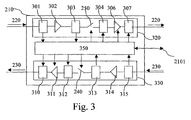
- Fig. 3 represents a schematic view of the master communication node of the optical network 200 according to the invention.
- the communication node master 210 is divided into two chains of 320 and 330 processed by a controller 350.
- the processing channel 320 processes the data circulating on the optical ring 220. It is composed of an optical extraction module 301 suitable for extract the information from the optical OSC monitoring channel.
- OSC is the acronym Optical Supervisory Channel.
- the processing chain 320 is also constituted of a reception optical amplifier 302, an optical extraction module 303 data for the telecommunication network or terminal connected to the node communication system 210 via the link 2101, a optical switch 250, an optical insertion module 304, data from the network or telecommunication terminal connected via the link 2101 to the communication node master 210, an optical transmission amplifier 306 and an information insertion module 307 in the supervisory channel optical OSC.
- the OSC Optical Supervision Channel is a channel at a wavelength predetermined, used for the transport of control information between different communication nodes of the optical network 200.
- the OSC channel is an autonomous communication channel. He is usually at the wavelength of 1510 nm.
- OSC optical monitoring channel unlike other channels conveying data, is not amplified in the optical network 200. This channel is among others and according to the invention used to verify whether, in the optical network 200, a or more optical rings are cut.
- the optical extraction module 301 extracts the information from the channel of OSC optical supervision.
- the optical extraction module 301 consists of a optical filter passes band tuned to the wavelength of the supervisory channel optical OSC.
- An unrepresented optical-electrical converter converts extracted from the OSC Optical Supervision Channel and transfers them to the controller 350.
- the optical extraction module 301 also comprises a rejection optical filter band tuned to the wavelength of the OSC optical supervisory channel.
- the data output from the optical extraction module 301 are then devoid of the information conveyed by the optical OSC monitoring channel.
- the optical reception amplifier 302 processes the optical signal from the module optical extraction 301.
- the receiving optical amplifier 302 is for example an erbium doped fiber amplifier.
- the optical reception amplifier 302 processes all the signals at different wavelengths of the optical network 200.
- the optical reception amplifier 302 amplifies, according to a particular mode, only a predetermined group of wavelengths among the set of signals at different wavelengths of the optical network 200.
- the optical reception amplifier 302 also comprises means for detection of loss or recovery of the optical signal. This loss or respectively this optical signal recovery is for example due to a cut, respectively to a repair, the portion of the optical ring 220 included between the communication node 211 and the master communication node 210.
- the receiving optical amplifier 302 is controlled by the controller 350. This amplifier 302 is able to switch to a power reduction mode of reception when no signal is detected or when it receives a command predetermined controller 350.
- the amplifier 302 is able to switch to an amplification mode normal when a signal is detected or when it receives a predetermined command of the controller 350.
- the signal at the output of the optical reception amplifier 302 is then transferred to the optical extraction module 303 data intended for the network or telecommunication terminal connected to the master communication node 210 by the link noted 2101.
- the optical extraction module 303 consists of an optical filter tuned to the or the wavelengths of the channels associated with the data intended for the network or telecommunication terminal connected to the master communication node 210 by the link 2101.
- a not shown optical-electrical converter converts the information from these channels and transfers them to the controller 350.
- the optical extraction module 303 also comprises a rejection optical filter band allocated to the wavelength (s) of the channel (s) associated with the data intended for the network or telecommunication terminal connected to the node of communication 210 by the link noted 2101. The output data of the optical extraction module 303 are then deprived of the data intended for the network or telecommunication terminal connected to the master communication node 210 through the link noted 2101.
- the signal at the output of the extraction module 303 is then transferred to the optical switch 250.
- the optical switch 250 in normal operation, that is to say when no deterioration or break in optical fiber exists in the network 200 optical, is in the open position.
- the optical switch 250 thus opens the ring 220 and thus avoids the problems of oscillations of the optical ring 220 and the problems related to the noise accumulation of different amplifiers present in the optical ring 220.
- the optical switch 250 when a deterioration or breakage of fiber optical exists in the optical network 200, is in the closed position. It ensures the transfer of the signal at the output of the extraction module 303 to the insertion module optical 304 data from the network or the connected telecommunications terminal through the link 2101 to the open communication node 210.
- the optical switch 250 is controlled by the controller 350 in accordance with the algorithm which will be described later with reference to FIG. 4.
- the signals at the output of the module 303 are multiplexed with data from the network or the terminal telecommunication connected via the link 2101 to the node of communication master 210.
- the optical transmission amplifier 306 amplifies the optical signal from the optical insertion module 304.
- the optical transmission amplifier 306 is example an erbium doped fiber amplifier.
- the optical transmission amplifier 306 amplifies all the signals at different wavelengths of the network optical 200 or in a particular mode only a predetermined group of wavelengths among all the signals at different wavelengths of the optical network 200.
- each communication node 210, 211, 212, 213 and 214 of the optical network 200 provides the amplification of a group of lengths wave. Amplification of all signals at different lengths of the optical network 200 is then provided by all the amplifiers optical transmission and / or reception of each network communication node 200 optical.
- the optical transmission amplifier 306 is controlled by the controller 350. This amplifier 306 is able to switch to a power reduction mode or vice versa when it receives a predetermined order from the 350. The advantages of such a feature will be described later in reference to FIG. 4.
- the optical insertion module 307 inserts the information of the OSC optical supervision delivered by the controller 350.
- the insertion module 307 inserts the supervisory data at the wavelength of the channel of OSC optical supervision.
- An optical-electrical converter, not shown converts the information delivered by the controller 350 into signals optics.
- the processing line 330 processes the data circulating on the optical ring 230. It is composed of an optical extraction module 315 adapted to extract the information from the optical OSC monitoring channel.
- the processing line 330 also consists of an optical amplifier of receiving 314, an optical extraction module 313 of data intended for the network or the telecommunication terminal connected to the master communication node 210 via the link 2101, an optical switch 240, a module optical insertion 312 data from the network or the terminal of telecommunication connected via the 2101 link to the node of communication 210, an optical transmission amplifier 311 and a information insertion module 310 in the OSC optical supervisory channel.
- the optical extraction module 315 is identical to the extraction module optical 301. It will not be described any more.
- the optical reception amplifier 314 is identical to the optical amplifier 302. It will not be more described.
- the optical extraction module 313 is identical to the extraction module optical 303. It will not be described any more.
- the optical switch 240 is identical to the optical switch 250. It will not be so no more described.
- the optical insertion module 312 is identical to the optical insertion module 304. It will not be described any more.
- the optical transmission amplifier 311 is identical to the optical amplifier issue 306. It will not be more described.
- the optical insertion module 310 is identical to the optical insertion module 307. It will not be described any more.
- the controller 350 of the master communication node 210 receives the monitoring information of the OSC channel of optical extraction module 301 and of the optical extraction module 315. This information is among other things information to check if the optical network has an optical fiber break.
- the controller 350 processes this information according to the algorithm that will be described later with reference to FIG. 4 and command among others the optical switches 240 and 250 according to this information.
- This same information is also processed by the controller 350 for control the generation of a signal on the OSC supervisory channels of optical rings 220 and 230 and thus control the optical transmission amplifiers communication nodes close to the cut.
- the controller 350 generates and / or transfers information to the optical insertion modules 307 and 310 so that these are transferred to the OSC channel of the optical network 200.
- control signals are for example control signals canceling the power reduction mode of optical amplifiers transmission of the communication nodes close to the cutoff.
- the controller 350 is also able to process information generated by one of the communication nodes of the optical network 200 representative of the detection by one of the communication nodes of detecting the loss or recovery of a optical signal on one of the optical rings 220 or 230.
- the controller 350 command the optical insertion module 307 or 310 for this information to be inserted in the OSC channel of rings 220 or 230 and thus be transferred to others nodes of the optical network 200.
- the controller 350 transfers the data received from the extraction modules 303 and 313 for the telecommunication network or terminal connected to the node of communication master 210 by the link noted 2101.
- the controller 350 transfers the data received from the network or the terminal of telecommunication connected to the communication node master 210 by the connection noted 2101 to insertion modules 304 and 312.
- the controller 350 includes at least one memory storing the instructions of the algorithm which will be described with reference to FIG. 4 and execute the instructions said algorithm.
- the communication nodes 211, 212, 213 and 214 have an architecture similar to the communication node master 210. These nodes comprise instead optical switches 240 and 250 optical links such as for example optical fiber.
- Fig. 4 represents the algorithm performed by the master communication node of the optical network 200 to secure the network.
- the controller 350 of the master communication node 210 reads from its memory the program instructions corresponding to steps E400 to E410 of the Fig. 4 and the RAM load not shown to execute them.
- the controller 350 Periodically or continuously, the controller 350 performs the various steps of the algorithm to determine if at least one fiber optic network is cut or not, and according to this determination, controls the switches 240 and 250.
- step E400 the controller 350 generates and / or transfers information to destination of the optical insertion module 307 so that they are transferred on the optical OSC optical control channel of the optical ring 220. This information are a test signal to determine whether the ring 220 is cut or not.
- step E401 transfers information to the optical insertion module 310 for these are transferred to the OSC optical supervisory channel of the optical ring 230.
- This information is a test signal to determine if the ring 230 is cut or not.
- steps E400 and E401 can be performed simultaneously.
- the controller instead of transferring information for optical insertion modules 307 and 310, transfers respectively the information for optical insertion modules 304 and 312 so that these are transferred respectively to a channel of the rings 220 and 230. This information is no longer transmitted along the length of the optical supervisory channel, but on one of the wavelengths associated with the data transmitted on the optical rings.
- step E402 consists in checking whether the signal transferred previously to step E400 has been extracted and transferred to the controller 350 by the optical extraction module 301 of the node of communication master 210.
- the ring 220 is cut. Indeed, in an operation normal of the optical ring 220, the signal transferred to the step E400 travels the entire of the ring 220 to finally return to the communication node master 210. If the ring is cut off, the signal transferred to step E400 will not propagate along the entire optical ring and therefore will not return to the communication node master 210.
- the processor 350 then proceeds to step E404 for the processing of this cut.
- step E403 If the optical extraction module 301 of the master communication node 210 has transmitted to the controller 350 the signal previously transferred to step E400, the ring 220 is not cut off, the controller 350 therefore proceeds to the next step E403.
- step E403 the controller 350 checks whether the signal transferred previously to step E401 was extracted by optical extraction module 315 from the node of communication master 210 and he was transferred.
- the controller 350 returns therefore at step E400 previously described and repeats steps E400 to E403 so that at least the ring 220 and / or the ring 230 is not considered cut.
- the optical extraction module 315 of the communication node master 210 did not transmit to the controller 350 the signal previously transferred to step E401, the ring 230 is cut.
- the controller 350 thus goes to the stage following E404.
- the controller 350 instead of transferring information to optical insertion modules 307 and 310, respectively transferred the information to destination of the optical insertion modules 304 and 312.
- the controller 350 checks the steps E402 and E403 if the previously transferred signals have been extracted and been transferred by optical extraction modules 303 and 313 from the communication master 210.
- step E404 the controller 350 controls the closing of the switches 240 and 250.
- the optical network 200 is then configured in a second mode Operating.
- step E405 which is identical at step E400. It will not be described anymore.
- step E406 which is identical at step E401. It will not be described anymore.
- step E407 which is identical in step E402. If the test of this step is negative, the controller 350 returns to step E405 and repeats the loop consisting of steps E405 to E407 as long as the break of the optical ring 220 has not been repaired.
- step E407 If the test of step E407 is positive, the controller 350 proceeds to step E408 which is identical to step E403. If the test in this step is negative, the controller 350 returns to step E405 and repeats the loop consisting of steps E405 to E408 as long as the cutting of the optical ring 230 has not been repaired.
- step E408 If the test of step E408 is positive, no optical fiber of the optical network 200 is cut off.
- the controller 350 goes to step E409 and then commands the opening switches 240 and 250.
- the controller 350 proceeds to the next step E410 and generates an information message on the OSC channel of one or each optical ring 220 and / or 230 to inform the other communication nodes 211, 212, 213 and 214 of the restoration of the optical network 200 in the first mode of operation, that is to say in normal operation.
- controllers of each communication node connected to the part of the ring previously cut then control their optical amplifier transmission to return to a normal amplification mode.
- controller 350 in parallel with the execution of the algorithm as described in FIG. 4, detects information transmitted on the channel OSC and representative of a loss of optical signal and generated by one of the nodes of communication of the optical network 200, the controller 350 confirms this information in performing the loop consisting of steps E400 to E403 to then proceed to step E404 and close the 240 and 250 optical switches.
- controller 350 in parallel with the execution of the algorithm as described in FIG. 4, detects information transmitted on the channel OSCs and representative of an optical signal recovery generated by one of the communication nodes of the optical network 200, the controller 350 proceeds to the step E409 and opens optical switches 240 and 250 if the recovery corresponds to a corresponding signal loss previously received.
- Fig. 5 represents an optical network according to the invention in which a ring optic optical network 200 is cut.
- the optical amplifier receiving the node communication 213 detects the loss of the optical signal and the controller of the node of communication 213 controls the transmit optical amplifier of the node of communication 213 associated with the communication ring 230 so that it switches to automatic power reduction mode.
- the optical signal at the output of the communication node 213 is then very strongly attenuated. This attenuation corresponds to an opening of the ring 230 on the part of the ring 230 included between the communication nodes 213 and 214.
- the optical signal at the output of the communication node 213 then being very greatly attenuated, the optical amplifier receiving the communication node 214 goes into the automatic power reduction mode.
- the controller of communication node 214 controls the transmission optical amplifier of the node communication 214 associated with the communication ring 220 so that it switches to automatic power reduction mode.
- the controller 350 of the communication node Master 210 has detected according to the algorithm as described with reference to FIG. 4, the existence of a break in the optical network 200.
- controller 350 of the master communication node 210 can alternatively use the information message on the OSC channel of the ring optical 220 to inform other communication nodes of this loss of signal as confirmation of the detection of a cut in the optical network 200.
- the controller 350 of the master communication node 210 then commands the closing switches 240 and 250 according to the algorithm described in Fig. 4.
- the node of communication 213 transfers to the optical network 200 data destined for the communication node 214
- the data are transmitted on the optical ring 230 following the arrow denoted 514 in FIG. 4.
- These data are strongly attenuated since the optical transmission amplifier of the communication node 213 is in the automatic reduction of gain.
- the ring 230 is thus open on the portion of the ring 230 between the communication nodes 213 and 214.
- the optical network 200 is configured according to the second operating mode.
- the rings 220 and 230 are open and thus avoid the problems related to noise and oscillations.
- Ring 230 is open because the optical signal is greatly attenuated by the optical transmission amplifier of the communication node 213.
- the cutoff noted A also opens the optical ring 220.
- each node of communication 210, 211, 212, 213 and 214 knows the configuration of the optical network 200 and transmits the data on the optical ring 220 or 230 allowing the transfer information to the destination node or the optical ring 220 or 230 having the shortest path between the sending node and the receiving node.
- the node of communication 213 transfers to the optical network 200 data destined for the communication node 214 only according to the path constituted by the arrows noted 500, 501, 502 and 503 in FIG. 5.
- the controller 350 of the communication node master 210 detects, in accordance with the algorithm as as described with reference to FIG. 4, the repair of the optical network 200, controls the optical switches 240 and 250 and generates an information message on the channel OSC of one or each optical ring 220 and / or 230 to inform others communication nodes 211, 212, 213 and 214 of the optical network restoration 200 according to the first mode of operation, that is to say in operation normal.
- any risk of oscillation of the ring optical when repairing the damaged optical ring is removed.
- the ring is closed, the optical switches 240 and 250 of the node of 210 master communication being open before the optical amplifiers transmission of the communication nodes connected to the part of the optical ring which was previously cut back into a normal boost mode.
- Fig. 6 represents an optical network according to the invention in which the two optical rings 220 and 230 forming the optical network 200 are cut.
- the controller 350 of the master communication node 210 generating at steps E400 and E401 test signals on the channels of supervision of the rings 220 and 230, detects in steps E402 and E403 the cuts of the rings optics 220 and 230.
- the controller 350 of the master communication node 210 controls the closing of the optical switches 240 and 250 and thus reconfiguring the network 200 optical.
- the optical network 200 then operates in the same manner as that described in reference to FIG. 5.
- the controller 350 of the master communication node 210 generates periodically or continuously test signals on the channels of supervision of the optical rings 220 and 230 to determine whether the cuts in rings 220 and 230 were repaired or not by an operator.
- the controller 350 maintains the 240 and 250 optical switches are closed.
- the controller 350 When, and only if both optical rings are repaired, the controller 350, according to step E409 of the algorithm of FIG. 4, order opening switches 240 and 250 to return to the first mode of operation.
- the communication node master 210 solves the problems of the state of the technique when one or more rings are cut.
- each optical ring unidirectionally.
- each optical ring can also convey information so bidirectional, that is to say in both directions of transmission.
- the communication nodes 210, 211, 212, 213 and 214 are adapted to operate in a bidirectional mode.
Landscapes
- Engineering & Computer Science (AREA)
- Computer Networks & Wireless Communication (AREA)
- Signal Processing (AREA)
- Physics & Mathematics (AREA)
- Electromagnetism (AREA)
- Optical Communication System (AREA)
- Small-Scale Networks (AREA)
Abstract
Description
Claims (9)
- Procédé de protection d'un réseau optique (200) configurable dans une première et une seconde configurations, le réseau optique étant constitué d'au moins une paire d'anneaux optiques ouverts (220, 230) reliant des noeuds de communication (210, 211, 212, 213, 214), un des noeuds de communication dit noeud de communication maítre (210) comportant des moyens d'ouverture et/ou de fermeture des anneaux optiques (240, 250), les anneaux optiques étant ouverts au niveau du noeud de communication maítre dans la première configuration, chaque extrémité de chaque anneau optique (220, 230) étant reliée au noeud de communication maítre, caractérisé en ce que chaque noeud de communication comporte des amplificateurs optiques d'émission (306, 311) et/ou de réception (302, 314) aptes à fonctionner dans un mode d'amplification des signaux véhiculés par les anneaux optiques ou à fonctionner dans un mode dit de réduction de puissance et en ce que le noeud de communication maítre (210) effectue les étapes de :génération (E405, E406) d'un signal prédéterminé à une extrémité de chaque anneau optique d'une paire d'anneaux optiques,détermination (E407, E408) de la présence du signal prédéterminé dans l'autre extrémité de chaque anneau optique,commande (E409) d'ouverture des moyens d'ouverture et/ou de fermeture des anneaux optiques si le signal prédéterminé est présent dans l'autre extrémité de chaque anneau optique pour configurer le réseau optique dans la première configuration,génération (E410) d'au moins un signal prédéterminé pour commander les amplificateurs d'émission et/ou de réception fonctionnant dans le mode dit de réduction de puissance à fonctionner dans le mode d'amplification des signaux véhiculés par les anneaux optiques.
- Procédé selon la revendication 1, caractérisé en ce que les moyens d'ouverture et/ou de fermeture des anneaux optiques sont des interrupteurs optiques (240, 250).
- Procédé selon la revendication 1 ou 2, caractérisé en ce que le réseau optique est un réseau à multiplexage de longueurs d'ondes, une longueur d'onde d'un canal de supervision étant associée à chaque anneau optique et en ce que le signal prédéterminé est généré sur chaque canal de supervision.
- Procédé selon la revendication 2 ou 3, caractérisé en ce que le procédé comporte en outre les étapes :génération (E400, E401) d'un signal prédéterminé à une extrémité de chaque anneau optique d'une paire d'anneaux optiques,détermination (E402, E403) de l'absence du signal prédéterminé dans au moins une autre extrémité de chaque anneau optique,commande (E404) de fermeture des interrupteurs optiques si le signal prédéterminé est absent dans au moins une autre extrémité d'un anneau optique pour configurer le réseau optique dans la seconde configuration.
- Procédé selon la revendication 4, caractérisé en ce que chaque noeud de communication (210, 211, 212, 213, 214) transfère des informations sur chaque anneau optique (220, 230) de la paire d'anneaux optiques à laquelle il est relié.
- Noeud de communication maítre (210) pour la protection d'un réseau optique (200) configurable dans une première et une seconde configurations, le réseau optique étant constitué d'au moins une paire d'anneaux optiques ouverts (220, 230) reliant des noeuds de communication (210, 211, 212, 213, 214), un des noeuds de communication dit noeud de communication maítre (210) comportant des moyens d'ouverture et/ou de fermeture (240, 250) des anneaux optiques (220, 230), les anneaux optiques étant ouverts au niveau du noeud de communication maítre dans une première configuration, chaque noeud de communication comporte des amplificateurs optiques d'émission (306, 311) et/ou de réception (302, 314) aptes à fonctionner dans un mode d'amplification des signaux véhiculés par les anneaux optiques ou à fonctionner dans un mode dit de réduction de puissance, caractérisé en ce que le noeud de communication maítre (210) comporte :des moyens de génération d'un signal prédéterminé à une extrémité de chaque anneau optique d'une paire d'anneaux optiques,des moyens de détermination de la présence du signal prédéterminé dans l'autre extrémité de chaque anneau optique,des moyens de commande d'ouverture des moyens d'ouverture et/ou de fermeture des anneaux optiques si le signal prédéterminé est présent dans l'autre extrémité de chaque anneau optique pour configurer le réseau optique dans la première configuration,des moyens de génération d'au moins un signal prédéterminé pour commander les amplificateurs d'émission et/ou de réception fonctionnant dans le mode dit de réduction de puissance à fonctionner dans le mode d'amplification des signaux véhiculés par les anneaux optiques.
- Noeud de communication maítre selon la revendication 6, caractérisé en ce que les moyens d'ouverture et/ou de fermeture des anneaux optiques sont des interrupteurs optiques (240, 250).
- Noeud de communication maítre selon la revendication 7, caractérisé en ce que le noeud de communication maítre (210) comporte en outre :des moyens de détermination (350, 301, 310) de l'absence du signal prédéterminé dans l'autre extrémité de chaque anneau optique,des moyens de commande (350) de fermeture des interrupteurs optiques si le signal prédéterminé est absent dans au moins une autre extrémité d'un anneau optique pour configurer le réseau optique dans la seconde configuration.
- Système de communication optique configurable dans une première et une seconde configurations, le système de communication optique étant constitué d'au moins une paire d'anneaux optiques (220, 230) ouverts reliant des noeuds de communication (210, 211, 212, 213, 214), un des noeuds de communication dit noeud de communication maítre (210) comportant des moyens (240, 250) d'ouverture et/ou de fermeture des anneaux optiques (220, 230), les anneaux optiques étant ouverts au niveau du noeud de communication maítre (210) dans la première configuration, chaque extrémité de chaque anneau optique étant reliée au noeud de communication maítre, caractérisé en ce que :le noeud de communication maítre (210) comporte :des moyens de génération (350, 307, 310) d'un signal prédéterminé à une extrémité de chaque anneau optique d'une paire d'anneaux optiques,des moyens de détermination (350, 301, 315) de l'absence ou la présence du signal prédéterminé dans au moins une autre extrémité d'un anneau optique (220, 230),des moyens de commande (350) de fermeture des moyens d'ouverture et/ou de fermeture des anneaux optiques (240, 250) si le signal prédéterminé est absent dans au moins une autre extrémité d'un anneau optique pour configurer le réseau optique (200) dans la seconde configuration,des moyens de commande d'ouverture (350) des moyens d'ouverture et/ou de fermeture des anneaux optiques (240, 250) si le signal prédéterminé est présent dans l'autre extrémité de chaque anneau optique (220, 230) pour configurer le réseau optique (200) dans la première configuration,les noeuds de communication (211, 212, 213, 214) comportent :des amplificateurs optiques d'émission (306, 311) et/ou de réception (302, 314) aptes à fonctionner dans un mode d'amplification des signaux véhiculés par les anneaux optiques ou à fonctionner dans un mode dit de réduction de puissance,des moyens de réception (350, 301, 315) d'au moins un message généré par le noeud de communication maítre pour changer le mode de fonctionnement des amplificateurs optiques d'émission et/ou de réception,des moyens de commande (350) des amplificateurs optiques d'émission et/ou de réception pour fonctionner selon l'un des deux modes de fonctionnement.
Applications Claiming Priority (2)
| Application Number | Priority Date | Filing Date | Title |
|---|---|---|---|
| FR0309726 | 2003-08-07 | ||
| FR0309726A FR2858729B1 (fr) | 2003-08-07 | 2003-08-07 | Procede, dispositif et systeme de protection d'un reseau optique constitue d'anneaux optiques |
Publications (2)
| Publication Number | Publication Date |
|---|---|
| EP1505750A1 true EP1505750A1 (fr) | 2005-02-09 |
| EP1505750B1 EP1505750B1 (fr) | 2006-08-30 |
Family
ID=33548318
Family Applications (1)
| Application Number | Title | Priority Date | Filing Date |
|---|---|---|---|
| EP20040077221 Expired - Lifetime EP1505750B1 (fr) | 2003-08-07 | 2004-08-03 | Procédé, dispositif et système de protection d'un réseau optique constitué d'anneaux optiques |
Country Status (3)
| Country | Link |
|---|---|
| EP (1) | EP1505750B1 (fr) |
| DE (1) | DE602004002156T2 (fr) |
| FR (1) | FR2858729B1 (fr) |
Citations (2)
| Publication number | Priority date | Publication date | Assignee | Title |
|---|---|---|---|---|
| WO2001017151A1 (fr) * | 1999-08-26 | 2001-03-08 | Impath Networks Inc. | Systeme de protection double destine a des anneaux mrf |
| WO2002080428A2 (fr) * | 2001-03-29 | 2002-10-10 | Atoga Systems, Inc. | Architectures en boucle ouverte pour reseaux wdm optiques |
Family Cites Families (1)
| Publication number | Priority date | Publication date | Assignee | Title |
|---|---|---|---|---|
| DE10207527B4 (de) * | 2002-02-22 | 2004-10-28 | Siemens Ag | Lokales Netzwerk, insbesondere Ethernet-Netzwerk, mit Redundanzeigenschaften sowie Koppelgerät für ein derartiges Netzwerk |
-
2003
- 2003-08-07 FR FR0309726A patent/FR2858729B1/fr not_active Expired - Lifetime
-
2004
- 2004-08-03 DE DE200460002156 patent/DE602004002156T2/de not_active Expired - Lifetime
- 2004-08-03 EP EP20040077221 patent/EP1505750B1/fr not_active Expired - Lifetime
Patent Citations (2)
| Publication number | Priority date | Publication date | Assignee | Title |
|---|---|---|---|---|
| WO2001017151A1 (fr) * | 1999-08-26 | 2001-03-08 | Impath Networks Inc. | Systeme de protection double destine a des anneaux mrf |
| WO2002080428A2 (fr) * | 2001-03-29 | 2002-10-10 | Atoga Systems, Inc. | Architectures en boucle ouverte pour reseaux wdm optiques |
Also Published As
| Publication number | Publication date |
|---|---|
| FR2858729A1 (fr) | 2005-02-11 |
| DE602004002156T2 (de) | 2007-01-04 |
| FR2858729B1 (fr) | 2007-04-27 |
| DE602004002156D1 (de) | 2006-10-12 |
| EP1505750B1 (fr) | 2006-08-30 |
Similar Documents
| Publication | Publication Date | Title |
|---|---|---|
| EP1879308B1 (fr) | Procédé et dispositif de surveillance des chemins optiques de connexion pour un réseau optique transparent | |
| FR2738432A1 (fr) | Composant optique adapte a la surveillance d'une liaison multilongueur d'onde et multiplexeur a insertion-extraction utilisant ce composant, application aux reseaux optiques | |
| EP0762691A2 (fr) | Procédé et système d'égalisation des niveaux respectifs de puissance des canaux d'un signal optique spectralement multiplexé | |
| FR2553951A1 (fr) | Dispositif de memorisation d'informations dans un systeme de transmission par fibre optique | |
| FR2473819A1 (fr) | Procede et systeme de securisation d'une artere de transmission numerique | |
| EP1434376B1 (fr) | Procédé et dispositif de contrôle de la puissance délivrée en sortie d'un noeud d'un réseau optique à commutation de bandes de longueurs d'onde | |
| FR2759834A1 (fr) | Reseau de transmission en anneau reconfigurable avec multiplexage en longueur d'onde pour liaisons semi-permanentes | |
| US6879434B2 (en) | Distributed raman amplifier for optical network and method | |
| EP1791272A1 (fr) | Dispositif de commutation optique à adjonction de signature pour le suivi des chemins optiques de connexion dans un réseau | |
| EP1351416A2 (fr) | Système et méthode d'amplification des signaux dans un réseau optique | |
| EP1505750B1 (fr) | Procédé, dispositif et système de protection d'un réseau optique constitué d'anneaux optiques | |
| EP1428333B1 (fr) | Reseau en anneau realise a partir d'un bus optique double | |
| FR2859054A1 (fr) | Controle dynamique de perte de puissance dans une fibre optique par contrapropagation d'un canal de supervision | |
| EP0720409A1 (fr) | Matrice de commutation photonique | |
| EP1592159B1 (fr) | Réseau de transmission optique en arbre | |
| EP3545631B1 (fr) | Détermination de noeuds relais régénérateurs compris dans une ligne de transmission d'un réseau optique | |
| EP2549773B1 (fr) | Dispositif et procédé de fusion de composantes optiques associées à une longueur d'onde en une composante optique fusionnée | |
| EP1804407B1 (fr) | Noeud d'accès pour réseau de transmission optique en anneau | |
| FR2828776A1 (fr) | Procede de securisation d'un systeme de transmission optique, dispositif pour la mise en oeuvre de ce procede et systeme de transmission optique incorporant un tel dispositif | |
| FR2935210A1 (fr) | Noeud de commutation de paquets optiques. | |
| EP4489328A1 (fr) | Procede et dispositif de gestion d'un defaut de fonctionnement d'une diode laser | |
| FR2761484A1 (fr) | Circuit multiplexeur d'insertion extraction optique et procede de transmission optique | |
| EP1331748A2 (fr) | Méthode de sécurisation d'un réseau de télécommunication optique en anneau ainsi que noeud de communication à amplification et concentrateur de trafic | |
| EP1492380A1 (fr) | Dispositif de traitement des signaux optiques, configurable, à sources large bande | |
| FR2813730A1 (fr) | Procede et dispositif de protection d'un reseau en anneau optique wdm centralise transportant des flux de donnees en mode connecte |
Legal Events
| Date | Code | Title | Description |
|---|---|---|---|
| PUAI | Public reference made under article 153(3) epc to a published international application that has entered the european phase |
Free format text: ORIGINAL CODE: 0009012 |
|
| AK | Designated contracting states |
Kind code of ref document: A1 Designated state(s): AT BE BG CH CY CZ DE DK EE ES FI FR GB GR HU IE IT LI LU MC NL PL PT RO SE SI SK TR |
|
| AX | Request for extension of the european patent |
Extension state: AL HR LT LV MK |
|
| 17P | Request for examination filed |
Effective date: 20050714 |
|
| GRAP | Despatch of communication of intention to grant a patent |
Free format text: ORIGINAL CODE: EPIDOSNIGR1 |
|
| AKX | Designation fees paid |
Designated state(s): DE GB |
|
| GRAS | Grant fee paid |
Free format text: ORIGINAL CODE: EPIDOSNIGR3 |
|
| RAP1 | Party data changed (applicant data changed or rights of an application transferred) |
Owner name: SAGEM COMMUNICATION |
|
| GRAA | (expected) grant |
Free format text: ORIGINAL CODE: 0009210 |
|
| AK | Designated contracting states |
Kind code of ref document: B1 Designated state(s): DE GB |
|
| REG | Reference to a national code |
Ref country code: GB Ref legal event code: FG4D Free format text: NOT ENGLISH |
|
| REF | Corresponds to: |
Ref document number: 602004002156 Country of ref document: DE Date of ref document: 20061012 Kind code of ref document: P |
|
| GBT | Gb: translation of ep patent filed (gb section 77(6)(a)/1977) |
Effective date: 20061219 |
|
| PLBE | No opposition filed within time limit |
Free format text: ORIGINAL CODE: 0009261 |
|
| STAA | Information on the status of an ep patent application or granted ep patent |
Free format text: STATUS: NO OPPOSITION FILED WITHIN TIME LIMIT |
|
| 26N | No opposition filed |
Effective date: 20070531 |
|
| REG | Reference to a national code |
Ref country code: GB Ref legal event code: 732E Free format text: REGISTERED BETWEEN 20090326 AND 20090401 |
|
| REG | Reference to a national code |
Ref country code: DE Ref legal event code: R082 Ref document number: 602004002156 Country of ref document: DE Representative=s name: BERENDT UND KOLLEGEN, DE |
|
| REG | Reference to a national code |
Ref country code: DE Ref legal event code: R082 Ref document number: 602004002156 Country of ref document: DE Representative=s name: PATENT- UND RECHTSANWAELTE HANSMANN & VOGESER, DE Effective date: 20120507 Ref country code: DE Ref legal event code: R081 Ref document number: 602004002156 Country of ref document: DE Owner name: SAGEMCOM ENERGY & TELECOM SAS, FR Free format text: FORMER OWNER: SAGEM COMMUNICATION, PARIS, FR Effective date: 20120507 Ref country code: DE Ref legal event code: R081 Ref document number: 602004002156 Country of ref document: DE Owner name: SAGEM ENERGY & TELECOM SAS, FR Free format text: FORMER OWNER: SAGEM COMMUNICATION, PARIS, FR Effective date: 20120507 Ref country code: DE Ref legal event code: R081 Ref document number: 602004002156 Country of ref document: DE Owner name: SAGEMCOM SAS, FR Free format text: FORMER OWNER: SAGEM COMMUNICATION, PARIS, FR Effective date: 20120507 Ref country code: DE Ref legal event code: R082 Ref document number: 602004002156 Country of ref document: DE Representative=s name: WEICKMANN & WEICKMANN, DE Effective date: 20120507 Ref country code: DE Ref legal event code: R082 Ref document number: 602004002156 Country of ref document: DE Representative=s name: WEICKMANN & WEICKMANN PATENTANWAELTE - RECHTSA, DE Effective date: 20120507 Ref country code: DE Ref legal event code: R082 Ref document number: 602004002156 Country of ref document: DE Representative=s name: WEICKMANN & WEICKMANN PATENT- UND RECHTSANWAEL, DE Effective date: 20120507 |
|
| REG | Reference to a national code |
Ref country code: DE Ref legal event code: R082 Ref document number: 602004002156 Country of ref document: DE Representative=s name: PATENT- UND RECHTSANWAELTE HANSMANN & VOGESER, DE |
|
| REG | Reference to a national code |
Ref country code: DE Ref legal event code: R081 Ref document number: 602004002156 Country of ref document: DE Owner name: SAGEMCOM ENERGY & TELECOM SAS, FR Free format text: FORMER OWNER: SAGEM TELECOMMUNICATIONS S. A., PARIS, FR Effective date: 20121120 Ref country code: DE Ref legal event code: R082 Ref document number: 602004002156 Country of ref document: DE Representative=s name: PATENT- UND RECHTSANWAELTE HANSMANN & VOGESER, DE Effective date: 20121120 Ref country code: DE Ref legal event code: R081 Ref document number: 602004002156 Country of ref document: DE Owner name: SAGEM ENERGY & TELECOM SAS, FR Free format text: FORMER OWNER: SAGEM TELECOMMUNICATIONS S. A., PARIS, FR Effective date: 20121120 Ref country code: DE Ref legal event code: R081 Ref document number: 602004002156 Country of ref document: DE Owner name: SAGEMCOM SAS, FR Free format text: FORMER OWNER: SAGEM TELECOMMUNICATIONS S. A., PARIS, FR Effective date: 20121120 Ref country code: DE Ref legal event code: R082 Ref document number: 602004002156 Country of ref document: DE Representative=s name: WEICKMANN & WEICKMANN, DE Effective date: 20121120 Ref country code: DE Ref legal event code: R082 Ref document number: 602004002156 Country of ref document: DE Representative=s name: WEICKMANN & WEICKMANN PATENTANWAELTE - RECHTSA, DE Effective date: 20121120 Ref country code: DE Ref legal event code: R082 Ref document number: 602004002156 Country of ref document: DE Representative=s name: WEICKMANN & WEICKMANN PATENT- UND RECHTSANWAEL, DE Effective date: 20121120 |
|
| REG | Reference to a national code |
Ref country code: DE Ref legal event code: R082 Ref document number: 602004002156 Country of ref document: DE Representative=s name: PATENT- UND RECHTSANWAELTE HANSMANN & VOGESER, DE |
|
| REG | Reference to a national code |
Ref country code: GB Ref legal event code: 732E Free format text: REGISTERED BETWEEN 20130221 AND 20130227 |
|
| REG | Reference to a national code |
Ref country code: DE Ref legal event code: R082 Ref document number: 602004002156 Country of ref document: DE Representative=s name: PATENT- UND RECHTSANWAELTE HANSMANN & VOGESER, DE Effective date: 20130129 Ref country code: DE Ref legal event code: R081 Ref document number: 602004002156 Country of ref document: DE Owner name: SAGEMCOM ENERGY & TELECOM SAS, FR Free format text: FORMER OWNER: SAGEMCOM SAS, RUEIL MALMAISON, FR Effective date: 20130213 Ref country code: DE Ref legal event code: R082 Ref document number: 602004002156 Country of ref document: DE Representative=s name: PATENT- UND RECHTSANWAELTE HANSMANN & VOGESER, DE Effective date: 20130213 Ref country code: DE Ref legal event code: R081 Ref document number: 602004002156 Country of ref document: DE Owner name: SAGEMCOM ENERGY & TELECOM SAS, FR Free format text: FORMER OWNER: SAGEM ENERGY & TELECOM SAS, RUEIL MALMAISON, FR Effective date: 20130129 Ref country code: DE Ref legal event code: R082 Ref document number: 602004002156 Country of ref document: DE Representative=s name: WEICKMANN & WEICKMANN, DE Effective date: 20130129 Ref country code: DE Ref legal event code: R082 Ref document number: 602004002156 Country of ref document: DE Representative=s name: WEICKMANN & WEICKMANN, DE Effective date: 20130213 Ref country code: DE Ref legal event code: R082 Ref document number: 602004002156 Country of ref document: DE Representative=s name: WEICKMANN & WEICKMANN PATENTANWAELTE - RECHTSA, DE Effective date: 20130213 Ref country code: DE Ref legal event code: R082 Ref document number: 602004002156 Country of ref document: DE Representative=s name: WEICKMANN & WEICKMANN PATENTANWAELTE - RECHTSA, DE Effective date: 20130129 Ref country code: DE Ref legal event code: R082 Ref document number: 602004002156 Country of ref document: DE Representative=s name: WEICKMANN & WEICKMANN PATENT- UND RECHTSANWAEL, DE Effective date: 20130213 Ref country code: DE Ref legal event code: R082 Ref document number: 602004002156 Country of ref document: DE Representative=s name: WEICKMANN & WEICKMANN PATENT- UND RECHTSANWAEL, DE Effective date: 20130129 |
|
| REG | Reference to a national code |
Ref country code: DE Ref legal event code: R082 Ref document number: 602004002156 Country of ref document: DE Representative=s name: WEICKMANN & WEICKMANN PATENTANWAELTE - RECHTSA, DE Ref country code: DE Ref legal event code: R082 Ref document number: 602004002156 Country of ref document: DE Representative=s name: WEICKMANN & WEICKMANN PATENT- UND RECHTSANWAEL, DE |
|
| PGFP | Annual fee paid to national office [announced via postgrant information from national office to epo] |
Ref country code: GB Payment date: 20230720 Year of fee payment: 20 |
|
| PGFP | Annual fee paid to national office [announced via postgrant information from national office to epo] |
Ref country code: DE Payment date: 20230720 Year of fee payment: 20 |
|
| REG | Reference to a national code |
Ref country code: DE Ref legal event code: R071 Ref document number: 602004002156 Country of ref document: DE |
|
| REG | Reference to a national code |
Ref country code: GB Ref legal event code: PE20 Expiry date: 20240802 |
|
| PG25 | Lapsed in a contracting state [announced via postgrant information from national office to epo] |
Ref country code: GB Free format text: LAPSE BECAUSE OF EXPIRATION OF PROTECTION Effective date: 20240802 |
|
| PG25 | Lapsed in a contracting state [announced via postgrant information from national office to epo] |
Ref country code: GB Free format text: LAPSE BECAUSE OF EXPIRATION OF PROTECTION Effective date: 20240802 |