EP1505614A2 - A modular switch and control system for use in a motor vehicle - Google Patents
A modular switch and control system for use in a motor vehicle Download PDFInfo
- Publication number
- EP1505614A2 EP1505614A2 EP04018461A EP04018461A EP1505614A2 EP 1505614 A2 EP1505614 A2 EP 1505614A2 EP 04018461 A EP04018461 A EP 04018461A EP 04018461 A EP04018461 A EP 04018461A EP 1505614 A2 EP1505614 A2 EP 1505614A2
- Authority
- EP
- European Patent Office
- Prior art keywords
- module
- satellite
- control system
- switch
- main
- Prior art date
- Legal status (The legal status is an assumption and is not a legal conclusion. Google has not performed a legal analysis and makes no representation as to the accuracy of the status listed.)
- Granted
Links
- 238000001514 detection method Methods 0.000 claims abstract description 6
- 238000000034 method Methods 0.000 claims 1
- 238000003032 molecular docking Methods 0.000 description 5
- 230000006870 function Effects 0.000 description 4
- 238000010586 diagram Methods 0.000 description 3
- 238000005286 illumination Methods 0.000 description 2
- 230000004913 activation Effects 0.000 description 1
- 239000011521 glass Substances 0.000 description 1
Images


Classifications
-
- H—ELECTRICITY
- H01—ELECTRIC ELEMENTS
- H01H—ELECTRIC SWITCHES; RELAYS; SELECTORS; EMERGENCY PROTECTIVE DEVICES
- H01H9/00—Details of switching devices, not covered by groups H01H1/00 - H01H7/00
- H01H9/02—Bases, casings, or covers
-
- H—ELECTRICITY
- H01—ELECTRIC ELEMENTS
- H01H—ELECTRIC SWITCHES; RELAYS; SELECTORS; EMERGENCY PROTECTIVE DEVICES
- H01H11/00—Apparatus or processes specially adapted for the manufacture of electric switches
- H01H11/0006—Apparatus or processes specially adapted for the manufacture of electric switches for converting electric switches
-
- H—ELECTRICITY
- H01—ELECTRIC ELEMENTS
- H01H—ELECTRIC SWITCHES; RELAYS; SELECTORS; EMERGENCY PROTECTIVE DEVICES
- H01H2223/00—Casings
- H01H2223/03—Separate key housing
- H01H2223/032—Separate key housing with formations for assembling similar housings
-
- H—ELECTRICITY
- H01—ELECTRIC ELEMENTS
- H01H—ELECTRIC SWITCHES; RELAYS; SELECTORS; EMERGENCY PROTECTIVE DEVICES
- H01H2300/00—Orthogonal indexing scheme relating to electric switches, relays, selectors or emergency protective devices covered by H01H
- H01H2300/03—Application domotique, e.g. for house automation, bus connected switches, sensors, loads or intelligent wiring
Definitions
- the present invention relates to a modular switch and control system for use in a motor vehicle.
- Motor vehicles usually have a rotary light switch for operating various lighting functions such as upper and lower beams, parking light and fog light.
- Other control elements may be provided for operating lighting related functions such as a range adjustment for the lower beams, an adjustment of the instrument illumination level or an activation of a headlamp glass washer.
- Such other control elements may be push button operated-switches or potentiometers that are operated through a rotary wheel, for example. They are usually accommodated in the instrument panel in positions next to the light switch.
- the modular switch and control system of the invention comprises a main switch module and optional satellite modules of different types.
- the main and satellite modules have separate housings with matching engagement structures permitting each satellite module to be fitted to one side of the main module.
- Each satellite module is electrically connected with the main module through matching male and female connectors.
- Each satellite module is provided with electrical coding means accessible through the connectors and permitting each satellite to be provided with a code indicative of the module type.
- the main module further includes detection means for accessing the coding means and detecting the type of connected satellite modules, and processing means for processing signals received from connected satellite modules and for generating control signals.
- the control signals are preferably applied through an appropriate interface to a bus installed in the vehicle, e.g. a CAN bus or a LIN bus.
- the main module which usually incorporates a rotary light switch, can be combined with optional satellite modules without the need for additional wiring.
- a satellite module when present, is detected and identified by the main module. Signals from any detected satellite module are processed by a digital controller and converted into control signals applied to a bus in the vehicle through an interface of the main module.
- Coding of the optional satellite modules can be accomplished in an easy way by means of resistive voltage dividers.
- the main module identifies a connected satellite module based on a voltage detected at the resistive voltage divider. Based on the detected type of satellite module, the main module converts any signals from a satellite module into appropriate digital control signals applied to the bus of the vehicle.
- a switch and control system for a motor vehicle which comprises a central main module 10 with a rotary light switch and two satellite modules 12, 14 connected at two opposed sides to main module 10.
- Each of the modules 10, 12 and 14 has a separate housing 10a, 12a and 14a, respectively, and a front panel 10b, 12b, 14b, respectively.
- Each of the modules 10, 12 and 14 has one or more operating elements.
- the front panels 10b, 12b and 14b together fit into a recess of the instrument panel in the particular vehicle for which the system is intended.
- Module 10 has a knob 10c for manual actuation of the associated rotary light switch (not shown).
- Module 12 has a rotary wheel 12c for actuation of a potentiometer (Fig. 5) and a pair of push buttons 12d, 12e.
- Module 14 also has a rotary wheel 14c for actuation of a potentiometer (not shown) and a pair of push buttons 14d, 14e.
- Satellite module 12 in the example considered is a control module mainly for a range control adjustment of the lower beams.
- Satellite module 14 in the example considered is a control module mainly for an adjustment of the illumination level of the instrument panel in the vehicle. Both satellite modules 12 and 14 may have additional control elements such as push buttons 12d, 12e in module 12 and push buttons 14d, 14e in module 14.
- the main module 10 is capable of detecting the presence (or not) of each satellite module and of receiving electrical signals from each switch or potentiometer in a connected satellite module to issue appropriate control signals on a system bus of the vehicle, as will be disclosed in more detail.
- Satellite modules 12 and 14 are both provided with a male mechanical connector element 16 and 18, respectively, that fits into a corresponding mechanical female connector 20, 22, respectively, on the corresponding side of the main module.
- Main module 10 also has a male electrical connector 24 for cooperation with a corresponding female electrical connector on satellite module 12.
- main module 10 also has a male electrical connector for cooperation with a corresponding female electrical connector 26 on satellite module 14.
- the main module 10 incorporates "intelligence" as materialized by a digital microcontroller 30 with a controller core " ⁇ C”, an associated memory 32 and an interface 34 to a bus system 36 installed in the vehicle.
- Microcontroller 30 has a first analog input "A/D 1" for connection to a first satellite module, a second analog input “A/D 2" for connection to a second satellite module and a supply voltage terminal "Power". The latter terminal is connected to input A/D 1 through a resistor R4 and to input "A/D 2" through a resistor R5, both resistors R4, R5 being equal in resistance value.
- Resistors R4 and R5 each are part of a resistive voltage divider that is supposed to be completed by one or more resistors in a connected satellite module.
- satellite module 12 has a docking terminal "Docking 1" and a ground terminal “GND”. Connected in series between both terminals are resistors R2 and R3. A switch SW is connected across (in parallel with) resistor R3. Switch SW may be operated by a push button in satellite module 12.
- satellite module 14 has a docking terminal "Docking 2", a ground terminal “GND” and a terminal “User Signal”.
- a potentiometer P is connected between terminals "Docking 2" and “GND” and has a tap connected to terminal "User Signal”.
- any satellite module can have one or more switches and one or more potentiometers, as required for a particular application.
- the main module is aware of satellite module types and the respective functionality provided. All possible satellite module types are coded by unambiguously associated resistive voltage divider ratios. These resistive voltage divider ratios are stored in memory 32 of digital microcontroller 30. By detecting the voltage drop at terminal "A/D 1" or "A/D 2", and matching the detected value with the contents of memory 32, the microcontroller 30 can identify each connected satellite module and associated functionality.
- the microcontroller 30 watches both of its inputs "A/D 1" and "A/D 2", identifies each connected satellite module and receives electrical signals from each connected module. The received signals are converted into appropriate control signals which are applied to bus 36 through interface 34. It should be understood that bus 36 is connected to driver circuitry installed within the vehicle for execution of corresponding controls.
Landscapes
- Engineering & Computer Science (AREA)
- Manufacturing & Machinery (AREA)
- Switches With Compound Operations (AREA)
- Selective Calling Equipment (AREA)
- Fittings On The Vehicle Exterior For Carrying Loads, And Devices For Holding Or Mounting Articles (AREA)
- Lighting Device Outwards From Vehicle And Optical Signal (AREA)
Abstract
Description
- The present invention relates to a modular switch and control system for use in a motor vehicle.
- Motor vehicles usually have a rotary light switch for operating various lighting functions such as upper and lower beams, parking light and fog light. Other control elements may be provided for operating lighting related functions such as a range adjustment for the lower beams, an adjustment of the instrument illumination level or an activation of a headlamp glass washer. Such other control elements may be push button operated-switches or potentiometers that are operated through a rotary wheel, for example. They are usually accommodated in the instrument panel in positions next to the light switch.
- Conventional switch and control systems for lighting and lighting related functions require complex wiring and assembly operations, all the more because some functions and related operating elements are optional and may only be installed in higher priced vehicles.
- The present invention provides a modular switch and control system for use in a motor vehicle, that is easily and flexibly adapted to the particular needs and requires no additional wiring for added modules. Specifically, the modular switch and control system of the invention comprises a main switch module and optional satellite modules of different types. The main and satellite modules have separate housings with matching engagement structures permitting each satellite module to be fitted to one side of the main module. Each satellite module is electrically connected with the main module through matching male and female connectors. Each satellite module is provided with electrical coding means accessible through the connectors and permitting each satellite to be provided with a code indicative of the module type. The main module further includes detection means for accessing the coding means and detecting the type of connected satellite modules, and processing means for processing signals received from connected satellite modules and for generating control signals. The control signals are preferably applied through an appropriate interface to a bus installed in the vehicle, e.g. a CAN bus or a LIN bus.
- In the inventive switch and control system, the main module, which usually incorporates a rotary light switch, can be combined with optional satellite modules without the need for additional wiring. A satellite module, when present, is detected and identified by the main module. Signals from any detected satellite module are processed by a digital controller and converted into control signals applied to a bus in the vehicle through an interface of the main module.
- Coding of the optional satellite modules can be accomplished in an easy way by means of resistive voltage dividers. The main module identifies a connected satellite module based on a voltage detected at the resistive voltage divider. Based on the detected type of satellite module, the main module converts any signals from a satellite module into appropriate digital control signals applied to the bus of the vehicle.
- Further advantages and details of the invention will become apparent from the following description of preferred embodiments with reference to the appending drawings. In the drawings:
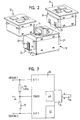
- Figure 1 is a perspective view of one embodiment of the modular switch and control system with a main module and two satellite modules;
- Figure 2 is a perspective view illustrating the mechanical and electrical association of the main and satellite modules;
- Figure 3 is a block diagram of a microcontroller-based detection and processing unit of the main module;
- Figure 4 is a schematic circuit diagram of a first satellite module; and
- Figure 5 is a schematic circuit diagram of a second satellite module.
- With reference now to Fig. 1, a switch and control system for a motor vehicle is shown which comprises a central
main module 10 with a rotary light switch and twosatellite modules main module 10. Each of themodules separate housing front panel modules front panels Module 10 has aknob 10c for manual actuation of the associated rotary light switch (not shown).Module 12 has arotary wheel 12c for actuation of a potentiometer (Fig. 5) and a pair ofpush buttons Module 14 also has a rotary wheel 14c for actuation of a potentiometer (not shown) and a pair ofpush buttons 14d, 14e. - The
satellite modules Satellite module 12 in the example considered is a control module mainly for a range control adjustment of the lower beams.Satellite module 14 in the example considered is a control module mainly for an adjustment of the illumination level of the instrument panel in the vehicle. Bothsatellite modules push buttons module 12 andpush buttons 14d, 14e inmodule 14. Themain module 10 is capable of detecting the presence (or not) of each satellite module and of receiving electrical signals from each switch or potentiometer in a connected satellite module to issue appropriate control signals on a system bus of the vehicle, as will be disclosed in more detail. - With reference now to Fig. 2, it is seen that the assembly mode of
modules Satellite modules mechanical connector element female connector Main module 10 also has a maleelectrical connector 24 for cooperation with a corresponding female electrical connector onsatellite module 12. Likewise,main module 10 also has a male electrical connector for cooperation with a corresponding femaleelectrical connector 26 onsatellite module 14. Whenmodules - The
main module 10 incorporates "intelligence" as materialized by adigital microcontroller 30 with a controller core "µC", an associatedmemory 32 and aninterface 34 to abus system 36 installed in the vehicle.Microcontroller 30 has a first analog input "A/D 1" for connection to a first satellite module, a second analog input "A/D 2" for connection to a second satellite module and a supply voltage terminal "Power". The latter terminal is connected to input A/D 1 through a resistor R4 and to input "A/D 2" through a resistor R5, both resistors R4, R5 being equal in resistance value. Resistors R4 and R5 each are part of a resistive voltage divider that is supposed to be completed by one or more resistors in a connected satellite module. - Referring to Fig. 4,
satellite module 12 has a docking terminal "Docking 1" and a ground terminal "GND". Connected in series between both terminals are resistors R2 and R3. A switch SW is connected across (in parallel with) resistor R3. Switch SW may be operated by a push button insatellite module 12. - Referring to Fig. 5,
satellite module 14 has a docking terminal "Docking 2", a ground terminal "GND" and a terminal "User Signal". A potentiometer P is connected between terminals "Docking 2" and "GND" and has a tap connected to terminal "User Signal". - It should be understood that any satellite module can have one or more switches and one or more potentiometers, as required for a particular application. The main module is aware of satellite module types and the respective functionality provided. All possible satellite module types are coded by unambiguously associated resistive voltage divider ratios. These resistive voltage divider ratios are stored in
memory 32 ofdigital microcontroller 30. By detecting the voltage drop at terminal "A/D 1" or "A/D 2", and matching the detected value with the contents ofmemory 32, themicrocontroller 30 can identify each connected satellite module and associated functionality. - In operation, the
microcontroller 30 watches both of its inputs "A/D 1" and "A/D 2", identifies each connected satellite module and receives electrical signals from each connected module. The received signals are converted into appropriate control signals which are applied tobus 36 throughinterface 34. It should be understood thatbus 36 is connected to driver circuitry installed within the vehicle for execution of corresponding controls.
Claims (10)
- A modular switch and control system for use in a motor vehicle, comprising a main switch module and optional satellite modules of different types, wherein the main and satellite modules have separate housings with matching engagement structures permitting each satellite module to be fitted to one side of the main module, each satellite module being electrically connected with the main module through matching male and female connectors, each satellite module being provided with electrical coding means accessible through said connectors and permitting each satellite to be provided with a code indicative of the module type, and the main module including detection means for accessing the coding means and detecting the type of connected satellite modules and processing means for processing signals received from connected satellite modules and generating control signals.
- The modular switch and control system of claim 1, wherein the electrical coding means include a resistive voltage divider and the code indicative of a module type is the dividing ratio of the voltage divider.
- The modular switch and control system of claim 2, wherein the resistive voltage divider comprises a first resistor connected to a supply voltage terminal of the main module and at least a second resistor connected in series with the first resistor, and the detection means detects a voltage drop at the interconnection node between the first and second resistors.
- The modular switch and control system of claim 3, wherein the main module includes a digital microcontroller with one analog input for each optional satellite module and with a memory for storing predetermined values of different voltage levels each associated with a different type of satellite module, said detection means and said processing means being materialized by said digital controller.
- The modular switch and control system according to any of the claims 1 to 4, wherein the main module includes a rotary light switch.
- The modular switch and control system according to any of the claims 1 to 5, wherein the optional satellite modules include at least one module with at least one push button-operated switch.
- The modular switch and control system according to claim 6 and any of claims 3 to 5, wherein the push button-operated switch is connected across a third resistor which is connected in series with the second resistor.
- The modular switch and control system according to any of the claims 1 to 7, wherein the optional satellite modules include at least one module with at least one potentiometer operated by a rotary wheel.
- The modular switch and control system according to any of the claims 4 to 8, wherein the digital microcontroller is connected to a bus of the vehicle.
- The modular switch and control system of claim 9, wherein the digital microcontroller of the main module processes voltage signals received from the satellite modules and generates control signals applied to the bus of the vehicle through an interface.
Applications Claiming Priority (2)
| Application Number | Priority Date | Filing Date | Title |
|---|---|---|---|
| DE10336582 | 2003-08-08 | ||
| DE10336582 | 2003-08-08 |
Publications (3)
| Publication Number | Publication Date |
|---|---|
| EP1505614A2 true EP1505614A2 (en) | 2005-02-09 |
| EP1505614A3 EP1505614A3 (en) | 2007-03-28 |
| EP1505614B1 EP1505614B1 (en) | 2011-11-16 |
Family
ID=33547167
Family Applications (1)
| Application Number | Title | Priority Date | Filing Date |
|---|---|---|---|
| EP04018461A Expired - Lifetime EP1505614B1 (en) | 2003-08-08 | 2004-08-04 | A modular switch and control system for use in a motor vehicle |
Country Status (4)
| Country | Link |
|---|---|
| US (1) | US7346436B2 (en) |
| EP (1) | EP1505614B1 (en) |
| JP (1) | JP4119874B2 (en) |
| CN (1) | CN100423148C (en) |
Cited By (2)
| Publication number | Priority date | Publication date | Assignee | Title |
|---|---|---|---|---|
| EP1788602A1 (en) * | 2005-11-17 | 2007-05-23 | TRW Automotive Electronics & Components GmbH & Co. KG | Rotary switch |
| CN107885211A (en) * | 2017-11-15 | 2018-04-06 | 国网湖南省电力有限公司 | A kind of fired power generating unit confined space inspection device and method |
Families Citing this family (33)
| Publication number | Priority date | Publication date | Assignee | Title |
|---|---|---|---|---|
| USD513737S1 (en) * | 2004-01-13 | 2006-01-24 | Harry Lee Riley | Controller |
| USD515038S1 (en) * | 2004-01-13 | 2006-02-14 | Harry Lee Riley | Controller |
| USD549184S1 (en) | 2006-01-23 | 2007-08-21 | Bachmann Industries, Inc. | Controller |
| USD549181S1 (en) | 2006-02-13 | 2007-08-21 | Bachmann Industries, Inc. | Controller |
| US9688162B2 (en) * | 2009-09-09 | 2017-06-27 | Honda Motor Co., Ltd. | Modular seat control switch system |
| US8447436B2 (en) | 2010-06-29 | 2013-05-21 | Harley-Davidson Motor Company Group, LLC | Handlebar control system |
| US9615428B2 (en) | 2011-02-01 | 2017-04-04 | John Joseph King | Arrangement for an outdoor light enabling motion detection |
| CN102887065B (en) * | 2011-07-21 | 2015-12-02 | 北汽福田汽车股份有限公司 | For time sharing automobile switch assembly and comprise its automobile |
| US9226373B2 (en) | 2013-10-30 | 2015-12-29 | John Joseph King | Programmable light timer and a method of implementing a programmable light timer |
| US10530597B1 (en) | 2017-04-01 | 2020-01-07 | Smart Power Partners LLC | System for controlling a plurality of power switches configured to apply power to devices |
| US12027968B2 (en) | 2017-04-01 | 2024-07-02 | John J. King | Power adapters and methods of implementing a power adapter |
| US12093004B1 (en) | 2017-04-01 | 2024-09-17 | Smart Power Partners LLC | In-wall power adapter and method of implementing an in-wall power adapter |
| US10996645B1 (en) | 2017-04-01 | 2021-05-04 | Smart Power Partners LLC | Modular power adapters and methods of implementing modular power adapters |
| US10727731B1 (en) | 2017-04-01 | 2020-07-28 | Smart Power Partners, LLC | Power adapters adapted to receive a module and methods of implementing power adapters with modules |
| US10965068B1 (en) | 2019-06-30 | 2021-03-30 | Smart Power Partners LLC | In-wall power adapter having an outlet and method of controlling an in-wall power adapter |
| US10958026B1 (en) | 2019-06-30 | 2021-03-23 | Smart Power Partners LLC | Contactless thermometer for an in-wall power adapter |
| US10938168B2 (en) | 2019-06-30 | 2021-03-02 | Smart Power Partners LLC | In-wall power adapter and method of controlling the application of power to a load |
| US11201444B1 (en) | 2019-06-30 | 2021-12-14 | Smart Power Partners LLC | Power adapter having contact elements in a recess and method of controlling a power adapter |
| US12164350B1 (en) | 2019-06-30 | 2024-12-10 | Smart Power Partners LLC | Power adapter configured to provide power to a load |
| US12066848B1 (en) | 2019-06-30 | 2024-08-20 | Smart Power Partners LLC | In-wall power adaper adapted to receive a control attachment and method of implementing a power adapter |
| US11460874B1 (en) | 2019-06-30 | 2022-10-04 | Smart Power Partners LLC | In-wall power adapter configured to control the application of power to a load |
| US11264769B1 (en) | 2019-06-30 | 2022-03-01 | Smart Power Partners LLC | Power adapter having contact elements in a recess and method of controlling a power adapter |
| US10917956B1 (en) | 2019-06-30 | 2021-02-09 | Smart Power Partners LLC | Control attachment configured to provide power to a load and method of configuring a control attachment |
| US11579640B1 (en) | 2019-06-30 | 2023-02-14 | Smart Power Partners LLC | Control attachment for an in-wall power adapter |
| US11189948B1 (en) | 2019-06-30 | 2021-11-30 | Smart Power Partners LLC | Power adapter and method of implementing a power adapter to provide power to a load |
| US11990718B1 (en) | 2019-06-30 | 2024-05-21 | Smart Power Partners LLC | Power adapter having a plurality of interfaces and methods of implementing a power adapter |
| US10958020B1 (en) | 2019-06-30 | 2021-03-23 | Smart Power Partners LLC | Control attachment for an in-wall power adapter and method of controlling an in-wall power adapter |
| US11231730B1 (en) | 2019-06-30 | 2022-01-25 | Smart Power Power LLC | Control attachment for a power adapter configured to control power applied to a load |
| US11043768B1 (en) | 2019-06-30 | 2021-06-22 | Smart Power Partners LLC | Power adapter configured to provide power to a load and method of implementing a power adapter |
| US12045071B1 (en) | 2019-06-30 | 2024-07-23 | Smart Power Partners LLC | In-wall power adapter having an outlet |
| US12300948B2 (en) | 2021-11-03 | 2025-05-13 | Smart Power Partners LLC | Control module having a control circuit and adapted to be attached to a power adapter |
| CN115763108A (en) * | 2022-11-29 | 2023-03-07 | 东风汽车股份有限公司 | An instrument panel combination switch and its disassembly method |
| WO2025172258A2 (en) * | 2024-02-14 | 2025-08-21 | Eaton Intelligent Power Limited | Test circuit and industrial device |
Citations (1)
| Publication number | Priority date | Publication date | Assignee | Title |
|---|---|---|---|---|
| EP0816176A2 (en) | 1996-06-26 | 1998-01-07 | Alps Electric Co., Ltd. | Automobile-installed-apparatus controller |
Family Cites Families (13)
| Publication number | Priority date | Publication date | Assignee | Title |
|---|---|---|---|---|
| US4346419A (en) * | 1981-04-27 | 1982-08-24 | Clairol Incorporated | Detachable plug |
| US4757525A (en) * | 1982-09-29 | 1988-07-12 | Vmx, Inc. | Electronic audio communications system with voice command features |
| GB8614198D0 (en) * | 1986-06-11 | 1986-07-16 | Salplex Ltd | Information handling & control systems |
| JPH01256242A (en) * | 1988-04-06 | 1989-10-12 | Hitachi Ltd | Control method for centralized wiring system |
| JP2879807B2 (en) * | 1992-07-30 | 1999-04-05 | 矢崎総業株式会社 | Switch corrosion prevention circuit |
| US5262602A (en) * | 1992-08-14 | 1993-11-16 | Fmc Corporation | High current and low current switch |
| DE4328663C1 (en) * | 1993-08-26 | 1994-06-09 | Grundig Emv | Vehicle radio operating-key-switches polling circuit - arranges switches in groups, and applies signal from each group via resistor and A=D converter to first inputs of microprocessor, and via respective signal shapers e.g. comparators, to second inputs of microprocessor |
| JP3144453B2 (en) * | 1994-03-23 | 2001-03-12 | 矢崎総業株式会社 | Switch device with switch discrimination function and operation switch |
| JP3333813B2 (en) * | 1996-11-20 | 2002-10-15 | トヨタ自動車株式会社 | Startup control device for occupant protection device |
| US5866862A (en) * | 1997-04-07 | 1999-02-02 | Ut Automotive Dearborn, Inc. | Vehicle positioning control |
| DE19845135A1 (en) * | 1997-10-25 | 1999-04-29 | Marquardt Gmbh | Electric operating switch for automobile electrical load |
| US20060287783A1 (en) * | 1998-01-15 | 2006-12-21 | Kline & Walker Llc | Automated accounting system that values, controls, records and bills the uses of equipment/vehicles for society |
| DE29816277U1 (en) * | 1998-09-10 | 1998-11-26 | Kuhnke GmbH, 23714 Malente | Electrical switching unit |
-
2004
- 2004-08-04 EP EP04018461A patent/EP1505614B1/en not_active Expired - Lifetime
- 2004-08-06 US US10/913,898 patent/US7346436B2/en active Active
- 2004-08-06 CN CNB2004100851039A patent/CN100423148C/en not_active Expired - Fee Related
- 2004-08-06 JP JP2004230823A patent/JP4119874B2/en not_active Expired - Fee Related
Patent Citations (1)
| Publication number | Priority date | Publication date | Assignee | Title |
|---|---|---|---|---|
| EP0816176A2 (en) | 1996-06-26 | 1998-01-07 | Alps Electric Co., Ltd. | Automobile-installed-apparatus controller |
Cited By (4)
| Publication number | Priority date | Publication date | Assignee | Title |
|---|---|---|---|---|
| EP1788602A1 (en) * | 2005-11-17 | 2007-05-23 | TRW Automotive Electronics & Components GmbH & Co. KG | Rotary switch |
| US7297889B2 (en) | 2005-11-17 | 2007-11-20 | Trw Automotive Electronics & Components Gmbh & Co. Kg | Rotary switch |
| CN107885211A (en) * | 2017-11-15 | 2018-04-06 | 国网湖南省电力有限公司 | A kind of fired power generating unit confined space inspection device and method |
| CN107885211B (en) * | 2017-11-15 | 2023-10-27 | 国网湖南省电力有限公司 | A thermal power unit confined space inspection device and method |
Also Published As
| Publication number | Publication date |
|---|---|
| CN100423148C (en) | 2008-10-01 |
| JP2005059845A (en) | 2005-03-10 |
| EP1505614A3 (en) | 2007-03-28 |
| US20050075741A1 (en) | 2005-04-07 |
| US7346436B2 (en) | 2008-03-18 |
| CN1595571A (en) | 2005-03-16 |
| JP4119874B2 (en) | 2008-07-16 |
| EP1505614B1 (en) | 2011-11-16 |
Similar Documents
| Publication | Publication Date | Title |
|---|---|---|
| US7346436B2 (en) | Modular switch and control system for use in a motor vehicle | |
| EP0822119B1 (en) | Multifunctional switching apparatus and a vehicle operating system using the same | |
| US6281453B1 (en) | Carrier and knob stop encoder assembly | |
| KR0152328B1 (en) | Multiplex communication system | |
| EP0816176B1 (en) | Automobile-installed-apparatus controller | |
| AU2018313784A1 (en) | Brake controller interface | |
| US7119456B2 (en) | Switch system capable of automatic configuration | |
| WO2015191378A1 (en) | Outside rear view mirror system | |
| AU730534B2 (en) | Touchtone electronic steering wheel | |
| CN109859978B (en) | Rocker switch and vehicle with same | |
| AU733238B2 (en) | Electronic steering wheel technique for passing information with a programmable current source and detector | |
| EP1063131B1 (en) | Alterable switch unit, and vehicle mounted device control apparatus including the same switch unit | |
| CA2121679A1 (en) | Vehicle operated romote control access system | |
| US6777824B2 (en) | Electronic mirror circuit and outside mirror assembly with such a circuit | |
| KR20110085166A (en) | Car Touch Switch Device | |
| US20030021048A1 (en) | Vehicle mirror control circuit arrangement | |
| JP2004111399A (en) | Vehicle-mounted equipment controlling device | |
| CN103581797A (en) | Loudspeaker driving circuit and steering device switch input detection circuit | |
| EP1221403A2 (en) | Multi-function steering-wheel | |
| US9586480B2 (en) | Automobiles, automobile instruments, and user interfaces for controlling automobile equipment | |
| US20070026741A1 (en) | Power plug with programmable functionality | |
| GB2394844A (en) | Circuit architecture for vehicle headlamp switch | |
| KR950009402B1 (en) | Automotive Multi Communication Control System | |
| WO2009094615A1 (en) | Flat panel touch interface for vehicle climate control system | |
| WO2022239564A1 (en) | Switch system and connection apparatus |
Legal Events
| Date | Code | Title | Description |
|---|---|---|---|
| PUAI | Public reference made under article 153(3) epc to a published international application that has entered the european phase |
Free format text: ORIGINAL CODE: 0009012 |
|
| AK | Designated contracting states |
Kind code of ref document: A2 Designated state(s): AT BE BG CH CY CZ DE DK EE ES FI FR GB GR HU IE IT LI LU MC NL PL PT RO SE SI SK TR |
|
| AX | Request for extension of the european patent |
Extension state: AL HR LT LV MK |
|
| PUAL | Search report despatched |
Free format text: ORIGINAL CODE: 0009013 |
|
| AK | Designated contracting states |
Kind code of ref document: A3 Designated state(s): AT BE BG CH CY CZ DE DK EE ES FI FR GB GR HU IE IT LI LU MC NL PL PT RO SE SI SK TR |
|
| AX | Request for extension of the european patent |
Extension state: AL HR LT LV MK |
|
| 17P | Request for examination filed |
Effective date: 20070730 |
|
| AKX | Designation fees paid |
Designated state(s): CZ DE FR GB IT |
|
| 17Q | First examination report despatched |
Effective date: 20100318 |
|
| GRAP | Despatch of communication of intention to grant a patent |
Free format text: ORIGINAL CODE: EPIDOSNIGR1 |
|
| GRAS | Grant fee paid |
Free format text: ORIGINAL CODE: EPIDOSNIGR3 |
|
| GRAA | (expected) grant |
Free format text: ORIGINAL CODE: 0009210 |
|
| RAP1 | Party data changed (applicant data changed or rights of an application transferred) |
Owner name: TRW AUTOMOTIVE ELECTRONICS & COMPONENTS GMBH |
|
| AK | Designated contracting states |
Kind code of ref document: B1 Designated state(s): CZ DE FR GB IT |
|
| REG | Reference to a national code |
Ref country code: GB Ref legal event code: FG4D |
|
| REG | Reference to a national code |
Ref country code: DE Ref legal event code: R096 Ref document number: 602004035291 Country of ref document: DE Effective date: 20120126 |
|
| PLBE | No opposition filed within time limit |
Free format text: ORIGINAL CODE: 0009261 |
|
| STAA | Information on the status of an ep patent application or granted ep patent |
Free format text: STATUS: NO OPPOSITION FILED WITHIN TIME LIMIT |
|
| 26N | No opposition filed |
Effective date: 20120817 |
|
| REG | Reference to a national code |
Ref country code: DE Ref legal event code: R097 Ref document number: 602004035291 Country of ref document: DE Effective date: 20120817 |
|
| PG25 | Lapsed in a contracting state [announced via postgrant information from national office to epo] |
Ref country code: CZ Free format text: LAPSE BECAUSE OF NON-PAYMENT OF DUE FEES Effective date: 20120804 |
|
| PG25 | Lapsed in a contracting state [announced via postgrant information from national office to epo] |
Ref country code: IT Free format text: LAPSE BECAUSE OF NON-PAYMENT OF DUE FEES Effective date: 20120804 |
|
| PGFP | Annual fee paid to national office [announced via postgrant information from national office to epo] |
Ref country code: GB Payment date: 20140827 Year of fee payment: 11 |
|
| REG | Reference to a national code |
Ref country code: FR Ref legal event code: PLFP Year of fee payment: 12 |
|
| GBPC | Gb: european patent ceased through non-payment of renewal fee |
Effective date: 20150804 |
|
| PG25 | Lapsed in a contracting state [announced via postgrant information from national office to epo] |
Ref country code: GB Free format text: LAPSE BECAUSE OF NON-PAYMENT OF DUE FEES Effective date: 20150804 |
|
| REG | Reference to a national code |
Ref country code: FR Ref legal event code: PLFP Year of fee payment: 13 |
|
| REG | Reference to a national code |
Ref country code: FR Ref legal event code: PLFP Year of fee payment: 14 |
|
| REG | Reference to a national code |
Ref country code: FR Ref legal event code: PLFP Year of fee payment: 15 |
|
| REG | Reference to a national code |
Ref country code: DE Ref legal event code: R082 Ref document number: 602004035291 Country of ref document: DE Representative=s name: PRINZ & PARTNER MBB PATENTANWAELTE RECHTSANWAE, DE Ref country code: DE Ref legal event code: R081 Ref document number: 602004035291 Country of ref document: DE Owner name: BCS AUTOMOTIVE INTERFACE SOLUTIONS GMBH, DE Free format text: FORMER OWNER: TRW AUTOMOTIVE ELECTRONICS & COMPONENTS GMBH, 78315 RADOLFZELL, DE |
|
| PGFP | Annual fee paid to national office [announced via postgrant information from national office to epo] |
Ref country code: FR Payment date: 20190822 Year of fee payment: 16 |
|
| PGFP | Annual fee paid to national office [announced via postgrant information from national office to epo] |
Ref country code: DE Payment date: 20200827 Year of fee payment: 17 |
|
| PG25 | Lapsed in a contracting state [announced via postgrant information from national office to epo] |
Ref country code: FR Free format text: LAPSE BECAUSE OF NON-PAYMENT OF DUE FEES Effective date: 20200831 |
|
| REG | Reference to a national code |
Ref country code: DE Ref legal event code: R119 Ref document number: 602004035291 Country of ref document: DE |
|
| PG25 | Lapsed in a contracting state [announced via postgrant information from national office to epo] |
Ref country code: DE Free format text: LAPSE BECAUSE OF NON-PAYMENT OF DUE FEES Effective date: 20220301 |