EP1505492A2 - Dynamic allocation method in digital signal processors - Google Patents
Dynamic allocation method in digital signal processors Download PDFInfo
- Publication number
- EP1505492A2 EP1505492A2 EP04015610A EP04015610A EP1505492A2 EP 1505492 A2 EP1505492 A2 EP 1505492A2 EP 04015610 A EP04015610 A EP 04015610A EP 04015610 A EP04015610 A EP 04015610A EP 1505492 A2 EP1505492 A2 EP 1505492A2
- Authority
- EP
- European Patent Office
- Prior art keywords
- dsp
- channels
- slave
- channel
- dsps
- Prior art date
- Legal status (The legal status is an assumption and is not a legal conclusion. Google has not performed a legal analysis and makes no representation as to the accuracy of the status listed.)
- Granted
Links
Images


Classifications
-
- G—PHYSICS
- G06—COMPUTING OR CALCULATING; COUNTING
- G06F—ELECTRIC DIGITAL DATA PROCESSING
- G06F9/00—Arrangements for program control, e.g. control units
- G06F9/06—Arrangements for program control, e.g. control units using stored programs, i.e. using an internal store of processing equipment to receive or retain programs
- G06F9/46—Multiprogramming arrangements
- G06F9/50—Allocation of resources, e.g. of the central processing unit [CPU]
- G06F9/5005—Allocation of resources, e.g. of the central processing unit [CPU] to service a request
- G06F9/5027—Allocation of resources, e.g. of the central processing unit [CPU] to service a request the resource being a machine, e.g. CPUs, Servers, Terminals
- G06F9/5044—Allocation of resources, e.g. of the central processing unit [CPU] to service a request the resource being a machine, e.g. CPUs, Servers, Terminals considering hardware capabilities
-
- G—PHYSICS
- G06—COMPUTING OR CALCULATING; COUNTING
- G06F—ELECTRIC DIGITAL DATA PROCESSING
- G06F9/00—Arrangements for program control, e.g. control units
- G06F9/06—Arrangements for program control, e.g. control units using stored programs, i.e. using an internal store of processing equipment to receive or retain programs
- G06F9/46—Multiprogramming arrangements
- G06F9/50—Allocation of resources, e.g. of the central processing unit [CPU]
- G06F9/5005—Allocation of resources, e.g. of the central processing unit [CPU] to service a request
- G06F9/5027—Allocation of resources, e.g. of the central processing unit [CPU] to service a request the resource being a machine, e.g. CPUs, Servers, Terminals
- G06F9/5055—Allocation of resources, e.g. of the central processing unit [CPU] to service a request the resource being a machine, e.g. CPUs, Servers, Terminals considering software capabilities, i.e. software resources associated or available to the machine
-
- G—PHYSICS
- G06—COMPUTING OR CALCULATING; COUNTING
- G06F—ELECTRIC DIGITAL DATA PROCESSING
- G06F2209/00—Indexing scheme relating to G06F9/00
- G06F2209/50—Indexing scheme relating to G06F9/50
- G06F2209/5015—Service provider selection
Definitions
- the present invention generally relates to the field of radio communications, and particularly to a dynamic allocation method in Digital Signal Processors (DSPs) for processing high and low speed channels.
- DSPs Digital Signal Processors
- the present invention provides a dynamic allocation method for DSP, which can process high and low speed channels at the same time.
- An object of the present invention is to provide a dynamic allocation method in DSPs for processing high and low speed channels.
- the method can process simultaneously both high and low speed channels in real time with limited processing resources and without practical detriment to either channel.
- the dynamic allocation method in DSPs of the present invention comprises steps of:
- Step b further comprises steps of:
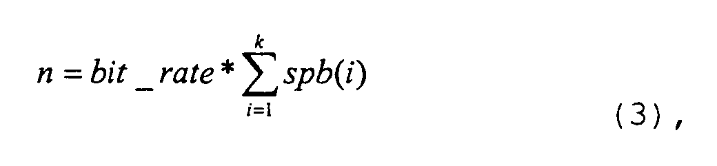
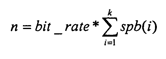
- Step b3 when the scheduler of the master DSP assigns two or more slave DSPs, the number of the slave DSPs is determined based on the following formula: where n indicates the number of DSPs required to process a channel, and the value of n is taken as an integer after being ed up; bit_rate indicates the bit rate of channel; spb(i) indicates the time required by each function in the SDR library of the DSP cluster to process each bit of a signal; i indicates the index number of function (subscript) in a signal processing function chain; k indicates the total number of functions in a signal processing function chain.
- Step b3 when the scheduler of the master DSP assigns two or more slave DSPs, the number of the slave DSPs is determined by means of a look up table, which is obtained previously by simulation experiments.
- Step c said slave DSP downloads the whole signal processing function chain from the SDR library of the DSP cluster to process said one or more channels.
- Step c When the scheduler of the master DSP assigns two or more slave DSPs to process one of said m channels in Step b3, in Step c, said two or more slave DSPs download continuous and relatively balanced function subchains of the whole signal processing function chain from the SDR library, and process said channel according to the continuity of each function subchain. That is, after processing one of said m channels, the slave DSP having downloaded the previous function subchain in the whole signal processing function chain transmits the processing results to the slave DSP having downloaded the next function subchain in the whole signal processing function chain to process one of said m channels. This procedure proceeds until said one of said m channels passes through the process of the whole signal processing function chain.
- bit_rate indicates the bit rate of channel
- spb(i) indicates the time required by each function in the SDR library of the DSP cluster to process each bit of a signal
- i indicates the index number of function (subscript) in a signal processing function chain
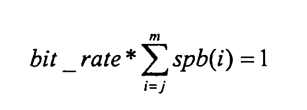
- j,m indicate the beginning and ending index numbers of function assigned to a particular DSP, respectively.
- the number of functions in the function subchain downloaded by each of said two or more slave DSPs may be determined by means of a look up table, which is obtained previously by simulation experiments.
- a DSP Digital Signal Processor
- SDR Software Defined Radio
- one of the DSPs is specified as a master DSP, the others are slave DSPs, and said master DSP comprises a scheduler for obtaining the bit rate of each of inputted m channels to be processed, where m is a positive integer greater than or equal to 1, and said scheduler of said master DSP assigns one or more channels of said m channels to at least one DSP in the DSP cluster based on the obtained bit rate of each of said m channels;
- each slave DSP assigned to each of said m channels downloads assigned corresponding signal processing function chain from the SDR library of said DSP cluster according to the assigned channel to be processed respectively, and outputs the processing results after processing each of said assigned m channels;
- said SDR library with signal processing functions comprises the whole signal processing function chain which is required to process a channel, and each slave DSP has access to the whole signal processing function chain in said SDR library, and said SDR library resides in a SDRAM (Synchronous Data RAM).
- Each DSP in the DSP cluster is connected to each other in any of a star configuration, a ring configuration or the combination of them via a common bus.
- the present invention takes advantage of SDR (Software Defined Radio) library and the different requirements for processing high and low speed channels in radio communications, to combine the processing method of high data rate channels and the processing method of low data rate channels into one DSP cluster, thus can process simultaneously both high and low data rate channels in the same DSP cluster.
- Said method can maintain the processing throughput of high data rate channels while reducing latency on low data rate channels, thus can improve the processing performance and save the cost.
- the present invention is realized based on the actual environments in radio communications. That is, generally, low data rate channels are used in the case where the condition of radio channels is not good and fast link adaptation methods are utilized to reduce latency, whereas high,data rate channels are used in the case where the condition of radio channels is good and latency is not important.
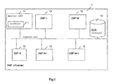
- Fig. 1 illustrates the basic configuration of the DSP cluster of the present invention.
- the DSP cluster 1 for processing high and low speed channels of the present invention comprises a master DSP 11, N slave DSPs 12 which are completely identical, where N is a positive integer greater than or equal to 1, and a SDR (Software Defined Radio) library 13 with signal processing functions.
- the master DSP and the slave DSPs are the same in the hardware structure.
- one of the DSPs is specified as a master DSP. and corresponding software for performing some functions is loaded into the specified DSP so as to differentiate between the master DSP and the slave DSPs in respect of their functions.
- the master DSP 11, the N slave DSPs 12 and the SDR library 13 are connected together in a star configuration via a common bus. Besides in a star configuration, the master DSP 11, the N slave DSPs 12 and the SDR library 13 may also be connected together in a ring configuration or the combination of star and ring configurations via a common bus (not shown).
- the master DSP 11 comprises a scheduler 111 for obtaining the bit rate of each of inputted m channels to be processed, where m is a positive integer greater than or equal to 1. And the scheduler 111 of said master DSP 11 assigns one or more channels of the m channels to at least one slave DSP 12 in the DSP cluster 1 based on the obtained data rate of each of said m channels. Meanwhile, said master DSP 11 also has a scheduling and real time operating system function.
- each DSP assigned to each channel downloads the corresponding signal processing function chain from the SDR library 13 of the DSP cluster 1 according to said assigned channel to be processed, and outputs the processing results after processing each assigned channel.
- the SDR (Software Defined Radio) library 13 with signal processing functions comprises the whole signal processing function chain which is required to process a channel.
- Each slave DSP has access to the whole signal processing function chain, wherein signal processing functions include encoding/decoding, rate matching, interleaving and so on.
- the SDR library resides in a SDRAM (Synchronous Data RAM).
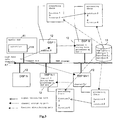
- Fig. 2 illustrates the process of low data rate channels in the DSP cluster of the present invention.
- low bit rate channels A, B, C, D, E to be processed are inputted into the DSP cluster 1 simultaneously, then the master DSP 11 in the DSP cluster obtains the bit rate of each of low data rate channels A, B, C, D, E.
- the obtained bit rate of each of low data rate channels A, B, C, D, E is compared with the bit rate of channel which a single slave DSP 12 in the DSP cluster can process. Since the bit rate of each of low data rate channels A, B, C, D and E is less than or equal to the bit rate of channel which a single slave DSP 12 in the DSP cluster can process, the scheduler 111 of the master DSP 11 assigns one slave DSP 12 respectively to process low data rate channels A, B, C, D, E. That is, the scheduler 111 of the master DSP 11 assigns channel A to DSP 1, a channel B to DSP M, channel C to DSP N, channel D to DSP N-1, and channel E to DSP M+1.
- DSP 1, DSP M, DSP N, DSP N-1 and DSP M+1 download the whole signal processing function chain including function 1 to function k from the SDR library 13 of the DSP cluster 1 respectively according to assigned low data rate of channels A, B, C, D, E to be processed, and output the processing results in the sequence of the signal processing function chain , i.e., from function 1 to function k, after processing assigned low data rate channels A, B, C, D, and E respectively.
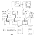
- Fig. 3 illustrates the process of high data rate channels in the DSP cluster of the present invention.
- high data rate channels X, Y to be processed are inputted into the DSP cluster 1 simultaneously, then the master DSP 11 in the DSP cluster obtains the bit rate of each of high data rate channels X, Y.
- the obtained bit rate of each of high data rate channels X, Y is compared with the bit rate of channel which a single slave DSP 12 in the DSP cluster can process. Since the bit rate of each of high data rate channels X, Y is greater than the bit rate of channel which a single slave DSP 12 in the DSP cluster can process, which indicates that only one slave DSP 12 is not able to execute the process of either of high data rate channels X, Y.
- the scheduler 111 of the master DSP 11 assigns two slave DSPs 12 to process high data rate channels X, Y, respectively. That is, the scheduler 111 of the master DSP 11 assigns high data rate channel X to DSP 1 and DSP M, and high data rate channel Y to DSP M+1 and DSP N-1.
- the scheduler 111 of the master DSP 11 may determine the number of slave DSPs 12 required to process one high data rate channel based on the following formula: where n indicates the number of DSPs required to process a channel, and the value of n is taken as an integer after being rounded up; bit_rate indicates the bit rate of channel; spb(i) indicates the time required by each function in the SDR library of the DSP cluster to process each bit of a signal; i indicates the index number of function (subscript) in a signal processing function chain; k indicates the total number of functions in a signal processing function chain.
- the number of slave DSPs 12 required to process one high data rate channel may be determined by means of a look up table, which is obtained previously by simulation experiments.
- DSP 1 and DSP M download continuous and relatively balanced function subchains in the whole signal processing function chain including function 1 to function k from the SDR library 13 respectively according to assigned high data rate channel X. That is, DSP 1 downloads function land function 2 from the SDR library 13, while DSPM downloads function 3 to function k from the SDR library 13.
- bit_rate indicates the bit rate of channel
- spb(i) indicates the time required by each function in the SDR library of DSP cluster to process each bit of a signal
- i indicates the index number of function (subscript) in a signal processing function chain
- j,m indicate the beginning and ending index numbers of function assigned to a particular DSP, respectively.
- the number of functions in the function subchain downloaded by each slave DSP 12 may be determined by means of a look up table which is obtained previously by simulation experiments.
- DSP 1 After processing high data rate channel X in turn according to function 1 and function 2 downloaded from the SDR library 13, DSP 1 transmits the processing results to the slave DSP 12 having downloaded the next subchain in the whole signal processing function chain, i.e., DSP M, which then processes high data rate channel X in turn according to function 3 to function k and outputs the processing results.
- DSP M+1 and DSP N-1 download continuous and relatively balanced function subchains in the whole signal processing function chain including function 1 to function k from the SDR library 13 respectively according to assigned high data rate channel Y. That is, DSP M+1 downloads function 1 and function 2 from the SDR library 13, while DSP N-1 downloads function 3 to function k from the SDR library 13.
- DSP 1 After processing high data rate channel Y in turn according to function 1 and function 2 downloaded from the SDR library 13, DSP 1 transmits the processing results to the slave DSP 12 having downloaded the next subchain in the whole signal processing function chain, i.e., DSP M, which then processes high data rate channel Y in turn according to function 3 to function k and outputs the processing results.
- Fig. 4 illustrates the parallel process of high and low data rate channels in the DSP cluster of the present invention.
- high and low data rate channels i.e., high data rate channel X and low data rate channels A, B
- the master DSP 11 in the DSP cluster 1 obtains the bit rates of high data rate channel X and low data rate channels A, B.
- bit rates of high data rate channel X and low data rate channels A, B are compared with the bit rate of channel which a single slave DSP 12 in the DSP cluster can process, respectively.
- the scheduler 111 of the master DSP 11 assigns one slave DSP 12 respectively to process low bit rate channels A, B. That is, the scheduler 111 of the master DSP 11 assigns a channel A to DSP M+1 and a channel B to DSP N-1.
- DSP M+1 and DSP N-1 download the whole signal processing function chain including function 1 to function k from the SDR library 13 of the DSP cluster 1 respectively according to assigned low data rate channels A, B to be processed, and output the processing results in the sequence of the signal processing function chain, i.e., from function 1 to function k, after processing assigned low data rate channels A, B respectively.
- the scheduler 111 of the master DSP 11 determines to assign two slave DSPs 12 to process high data rate channel X based on the formula (1). That is, the scheduler 111 of the master DSP 11 assigns high data rate channel X to DSP1 and DSPM.
- the number of slave DSPs 12 required to process one high data rate channel may be determined by means of a look up table which is obtained previously by simulation experiments.
- DSP 1 and DSP M download continuous and relatively balanced function subchains in the whole signal processing function chain including function 1 to function k from the SDR library 13 according to assigned high data rate channel X based on the formula (2). That is, DSP 1 downloads function 1 and function 2 from the SDR library 13, while DSP M downloads function 3 to function k from the SDR library 13.
- the number of functions in the function subchain downloaded by each slave DSP 12 may be determined by means of a look up table which is obtained previously by simulation experiments.
- DSP 1 After processing high data rate channel X in turn according to function 1 and function 2 downloaded from the SDR library 13, DSP 1 transmits the processing results to the slave DSP 12 having downloaded the next subchain in the whole signal processing function chain, i.e., DSP M, which then processes high data rate channel X in turn according to function 3 to function k and outputs the processing results.
- the dynamic allocation method in DSPs comprises steps of:
- Step b further comprises steps of:
- Step b3 when the scheduler of the master DSP assigns two or more slave DSPs, the number of slave DSPs is determined based on the following formula: where n indicates the number of DSPs required to process a channel, the value of n is taken as an integer after being rounded up; bit_rate indicates the bit rate of channel; spb(i) indicates the time required by each function in the SDR library of the DSP cluster to process each bit of a signal; i indicates the index number of function (subscript) in a signal processing function chain; k indicates the total number of functions in a signal processing function chain.
- Step b3 when the scheduler of the master DSP assigns two or more slave DSPs, the number of the slave DSPs is determined by means of a look up table, which is obtained previously by simulation experiments.
- Step c said slave DSP downloads the whole signal processing function chain from the SDR library of the DSP cluster to process said one or more channels.
- Step c When the scheduler of the master DSP assigns two or more slave DSPs to process one of said m channels in Step b3, in Step c, said two or more slave DSPs download continuous and relatively balanced function subchains in the whole signal processing function chain from the SDR library of the DSP cluster, and process said channel according to the continuity of each function subchain. That is, after processing one of said m channels, the slave DSP having downloaded the previous function subchain in the whole signal processing function chain transmits the processing results to the slave DSP having downloaded the next function subchain in the whole signal processing function chain to process one of said m channels. This procedure proceeds until one of said m channels passes through the process of the whole signal processing function chain.
- bit_rate indicates the bit rate of channel
- spb(i) indicates the time required by each function in the SDR library of the DSP cluster to process each bit of a signal
- i indicates the index number of function (subscript) in a signal processing function chain
- j,m indicate the beginning and ending index numbers of function assigned to a particular DSP respectively.
- the number of functions in the function subchain downloaded by each of said two or more slave DSPs may be determined by means of a look up table, which is obtained previously by simulation experiments.
- Fig. 5 illustrates the configuration of a DDD (Downlink Decoding and De-spreading) DSP cluster according to one embodiment of the present invention.
- the embodiment of the present invention is applied to process HS-DSCH (High Speed Downlink Shared Channels) signals of HSDPA (High Speed Downlink Packet Access) on the current Evolium Node B V2 Base Band Processing Board for UMTS (Universal Mobile Telecommunication Systems).
- the DDD (Downlink Decoding and De-spreading) DSP cluster comprises a master DSP (not shown), 5 completely identical slave DSPs 51 and a SDR (Software Defined Radio) library with signal processing functions (not shown).
- Said master DSP (not shown), 5 completely identical slave DSPs 51 and SDR library (not shown) are connected to each other in the combination of star and ring configurations via a common bus.
- each slave DSP 51 can process a 3Mbit/s channel in downlink with constant throughput.
- HSDPA High Speed Downlink Packet Access
- HS-DSCH High Speed Downlink Shared Channels
- the entire HS-DSCH can be used by one mobile station or shared amongst many mobile stations.
- the data rate of a single mobile station may range from 0Mbit/s to 14.4Mbit/s or the sum of the bit rates of many mobile stations is lower than 14.4Mbit/s.
- each slave DSP 51 shown in Fig. 5 is capable to process a 3Mbit/s channel in downlink with constant throughput
- the scheduler of the master DSP assigns the channels of which the sum of the data rates is less than or equal to 3Mbit/s to one DSP, and assigns the channel with a data rate greater than 3Mbit/s to two or more DSPs based on the formula (1). That is, as shown in Fig. 5, the scheduler of the master DSP assigns the channels at 1Mbit/s and 2Mbit/s to DSP 1, the channel at 3Mbit/s to DSP 2 and the channel at 6Mbit/s to DSP 4 and DSP 5.
- DSP 1, DSP 2 download the whole signal processing function chain from the SDR library (not shown) according to the assigned channels respectively, and output the processing results after processing the assigned channels.
- the signal processing function chain in the SDR library (not shown) is shown as Fig. 6.
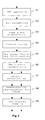
- Fig. 6 illustrates the signal processing function chain for processing the HS-DSCH (High Speed Downlink Shared Channels) according to the embodiment of the present invention.
- Said signal processing function chain is included in the SDR library of Fig. 5 (not shown).
- Each slave DSP 51 has access to said signal processing function chain of the SDR library (not shown), which is shown in Fig. 6.
- Fig. 6 illustrates the signal processing function chain for processing the HS-DSCH (High Speed Downlink Shared Channels) according to the embodiment of the present invention.
- Said signal processing function chain is included in the SDR library of Fig. 5 (not shown).
- Each slave DSP 51 has access to said signal processing function chain of the SDR library (not shown), which is shown in Fig. 6.
- Fig. 6 illustrates the signal processing function chain for processing the HS-DSCH (High Speed Downlink Shared Channels)
- said signal processing function chain for processing HS-DSCH (High Speed Downlink Channels) signals comprises CRC appending 61, bit scrambling 62, code block segmentation 63, channel coding 64, PHY layer HARQ (Hybrid-ARQ) functionality 65, PHY channel segmentation 66, HS-DSCH signals interleaving 67, constellation rearrangement for 16QAM 68, PHY channel mapping 69 in turn.
- DSP 1 processes the channels at 1Mbit/s and 2Mbit/s according to the signal processing function chain shown in Fig. 6 and then outputs the processing results.
- DSP 2 processes the channel at 3Mbit/s according to the signal processing function chain shown in Fig. 6 and then outputs the processing results.
- DSP 4 and DSP 5 download continuous and relatively balanced function subchains in the whole signal processing function chain from said SDR library (not shown), process the assigned channels and then output the processing results. That is, DSP 4 downloads CRC appending 61, bit scrambling 62, code block segmentation 63, channel coding 64, PHY layer HARQ functionality 65, which are shown in Fig. 6, from said SDR library (not shown). After processing the channel at 6Mbit/s in turn according to the above 5 functions, DSP 4 transmits the processing results to DSP 5 along high speed ring with ring configuration so as to avoid overloading the common bus.
- DSP 5 downloads PHY channel segmentation 66, HS-DSCH signals interleaving 67, constellation rearrangement for 16QAM 68, PHY channel mapping 69, which are shown in Fig. 6, from said SDR library (not shown). After processing the processing results from DSP 4 in turn according to the above 4 functions, DSP 5 outputs the processing results.
Landscapes
- Engineering & Computer Science (AREA)
- Software Systems (AREA)
- Theoretical Computer Science (AREA)
- Physics & Mathematics (AREA)
- General Engineering & Computer Science (AREA)
- General Physics & Mathematics (AREA)
- Mobile Radio Communication Systems (AREA)
Abstract
Description

bit_rate indicates the bit rate of channel;
spb(i) indicates the time required by each function in the SDR library of the DSP cluster to process each bit of a signal;
i indicates the index number of function (subscript) in a signal processing function chain;
k indicates the total number of functions in a signal processing function chain.

spb(i) indicates the time required by each function in the SDR library of the DSP cluster to process each bit of a signal;
i indicates the index number of function (subscript) in a signal processing function chain;
j,m indicate the beginning and ending index numbers of function assigned to a particular DSP, respectively.
said SDR library with signal processing functions comprises the whole signal processing function chain which is required to process a channel, and each slave DSP has access to the whole signal processing function chain in said SDR library, and said SDR library resides in a SDRAM (Synchronous Data RAM).

bit_rate indicates the bit rate of channel;
spb(i) indicates the time required by each function in the SDR library of the DSP cluster to process each bit of a signal;
i indicates the index number of function (subscript) in a signal processing function chain;
k indicates the total number of functions in a signal processing function chain.

spb(i) indicates the time required by each function in the SDR library of DSP cluster to process each bit of a signal;
i indicates the index number of function (subscript) in a signal processing function chain;
j,m indicate the beginning and ending index numbers of function assigned to a particular DSP, respectively.
bit_rate indicates the bit rate of channel;
spb(i) indicates the time required by each function in the SDR library of the DSP cluster to process each bit of a signal;
i indicates the index number of function (subscript) in a signal processing function chain;
k indicates the total number of functions in a signal processing function chain.

spb(i) indicates the time required by each function in the SDR library of the DSP cluster to process each bit of a signal;
i indicates the index number of function (subscript) in a signal processing function chain;
j,m indicate the beginning and ending index numbers of function assigned to a particular DSP respectively.
Claims (11)
- A dynamic allocation method in Digital Signal Processors (DSPs) for processing high and low data rate channels, comprising steps of:a. inputting m channels to be processed into a DSP cluster, and obtaining by a master DSP in said DSP cluster a bit rate of each one of said m channels, wherein m is a positive integer greater than or equal to 1;b. assigning, by a scheduler of said master DSP, one or more channels of said m channels to at least one slave DSP in said DSP cluster based on said bit rates of said m channels obtained in said step a;c. downloading, by each slave DSP to which one or more of said m channels have been assigned, from a Software Defined Radio (SDR) library of said DSP cluster, assigned corresponding signal processing function chain, based on assigned channels to be processed, and outputting processing results after said assigned channels have been processed.
- The dynamic allocation method in Digital Signal Processors according to Claim 1, wherein said Step b further comprises steps:b1. comparing said bit rate of each of said m channels with a bit rate of channel which a single slave DSP in the DSP cluster can process;b2. assigning, by the scheduler of the master DSP, one slave DSP to process said one channel or more than one channels when the bit rate of one of said m channels or the sum of the bit rates of more than one of said m channels is less than or equal to the bit rate of channel which a single slave DSP of the DSP cluster can process ;b3. assigning, by the scheduler of the master DSP, two or more slave DSPs to process said channel when the bit rate of one of said m channels is greater than the bit rate of channel which a single slave DSP in the DSP cluster can process.
- The dynamic allocation method in Digital Signal Processors according to Claim 2, wherein in said Step b3, when the scheduler of the master DSP assigns two or more slave DSPs to process said channel, the number of the slave DSPs is determined based on the following formula:where n indicates the number of DSPs required to process a channel, and the value of n is taken as an integer after being rounded up;
bit_rate indicates the bit rate of channel;
spb(i) indicates the time required by each function in the SDR library of the DSP cluster to process each bit of a signal;
i indicates the index number of function (subscript) in a signal processing function chain;
k indicates the total number of functions in a signal processing function chain. - The dynamic allocation method in Digital Signal Processors according to Claim 2, wherein in said Step b3, when the scheduler of the master DSP assigns two or more slave DSPs to process said channel, the number of the slave DSPs is determined by means of a look up table, which is obtained previously by simulation experiments.
- The dynamic allocation method in Digital Signal Processors according to Claim 2, wherein when the scheduler of the master DSP assigns one slave DSP to process one or more of said m channels in said Step b2, in said Step c, said slave DSP downloads the whole signal processing function chain from the SDR library of the DSP cluster to process said one or more channels.
- The dynamic allocation method in Digital Signal Processors according to Claim 2, wherein when said scheduler of said master DSP assigns two or more slave DSPs to process one of said m channels in said Step b3, in said Step c, said two or more slave DSPs download continuous and relatively balanced function subchains in the whole signal processing function chain from the SDR library of said DSP cluster, and process said channel according to the continuity of each function subchain, that is, after processing said one of said m channels, said slave DSP having downloaded the previous function subchain in the whole signal processing function chain transmits the processing results to the slave DSP having downloaded the next function subchain in the whole signal processing function chain to process said one of said m channels, and this procedure proceeds until said one of said m channels passes through the process of the whole signal processing function chain.
- The dynamic allocation method in Digital Signal Processors according to Claim 5, wherein the number of functions in the function subchain downloaded by each of said two or more slave DSPs may be determined based on the following formula:where n indicates the number of DSPs required to process a channel, and the value of n is taken as an integer after being rounded up;
bit_rate indicates the bit rate of channel;
spb(i) indicates the time required by each function in the SDR library of the DSP cluster to process each bit of a signal;
i indicates the index number of function (subscript) in a signal processing function chain;
j,m indicate the beginning and ending index numbers of function allocated to a particular DSP respectively. - The dynamic allocation method in Digital Signal Processors according to Claim 5, wherein the number of functions in the function subchain downloaded by each of said two or more slave DSPs is determined by means of a look up table, which is obtained previously by simulation experiments.
- A Digital Signal Processor (DSP) cluster for processing high and low data rate channels, comprising a group of completely identical DSPs and a SDR (Software Defined Radio) library with signal processing functions, said group of completely identical DSPs and said SDR library being connected to each other via a common bus, wherein:in said group of completely identical DSPs, one of the DSPs is specified as a master DSP and the others are slave DSPs, said master DSP comprises a scheduler for obtaining the bit rate of each of said inputted m channels to be processed, where m is a positive integer greater than or equal to 1, and said scheduler of said master DSP assigns one or more channels of said m channels to at least one slave DSP in the DSP cluster based on the obtained bit rate of each of said m channels;in said slave DSPs, each slave DSP assigned to each of said m channels downloads assigned corresponding signal processing function chain from the SDR library of said DSP cluster according to the assigned channel to be processed, and outputs the processing results after processing each of said assigned m channels;said SDR library with signal processing functions comprises the whole signal processing function chain which is required to process one channel, and each slave DSP has access to said whole signal processing function chain in said SDR library.
- The DSP cluster according to Claim 5, wherein each DSP in said DSP cluster is connected to each other in a star configuration, a ring configuration or the combination of star and ring configurations via a common bus.
- The DSP cluster according to Claim 5, wherein said SDR library resides in a SDRAM (Synchronous Data RAM).
Applications Claiming Priority (2)
| Application Number | Priority Date | Filing Date | Title |
|---|---|---|---|
| CN031419712A CN1581722B (en) | 2003-07-31 | 2003-07-31 | Dynamic distributing method for digital signal processor (DSP) and digital signal processor cluster |
| CN03141971 | 2003-07-31 |
Publications (3)
| Publication Number | Publication Date |
|---|---|
| EP1505492A2 true EP1505492A2 (en) | 2005-02-09 |
| EP1505492A3 EP1505492A3 (en) | 2007-10-31 |
| EP1505492B1 EP1505492B1 (en) | 2018-06-27 |
Family
ID=33546191
Family Applications (1)
| Application Number | Title | Priority Date | Filing Date |
|---|---|---|---|
| EP04015610.1A Expired - Lifetime EP1505492B1 (en) | 2003-07-31 | 2004-07-02 | Dynamic allocation method in digital signal processors |
Country Status (3)
| Country | Link |
|---|---|
| US (1) | US7580413B2 (en) |
| EP (1) | EP1505492B1 (en) |
| CN (1) | CN1581722B (en) |
Families Citing this family (13)
| Publication number | Priority date | Publication date | Assignee | Title |
|---|---|---|---|---|
| US7885409B2 (en) | 2002-08-28 | 2011-02-08 | Rockwell Collins, Inc. | Software radio system and method |
| US7769912B2 (en) * | 2005-02-17 | 2010-08-03 | Samsung Electronics Co., Ltd. | Multistandard SDR architecture using context-based operation reconfigurable instruction set processors |
| CN100579146C (en) * | 2005-09-02 | 2010-01-06 | 深圳市东进通讯技术股份有限公司 | Module configuration management method in integrated telecommunication platform |
| US7720506B1 (en) | 2006-07-28 | 2010-05-18 | Rockwell Collins, Inc. | System and method of providing antenna specific front ends for aviation software defined radios |
| US7831255B1 (en) | 2006-07-31 | 2010-11-09 | Rockwell Collins, Inc. | System and method of providing automated availability and integrity verification for aviation software defined radios |
| US7809872B2 (en) * | 2007-12-14 | 2010-10-05 | Infineon Technologies Ag | Master and slave device for communicating on a communication link with limited resource |
| CN101803213B (en) * | 2007-12-28 | 2014-12-03 | 诺基亚公司 | Multiradio Example Using Software Defined Radio |
| CN101217341B (en) * | 2008-01-03 | 2011-11-30 | 中兴通讯股份有限公司 | A fast velocity matching method |
| US8135771B2 (en) * | 2009-07-27 | 2012-03-13 | Cisco Technology, Inc. | Digital signal processor clustering in integrated media-services gateways |
| CN102395203B (en) * | 2011-10-25 | 2014-09-10 | 大唐移动通信设备有限公司 | Distribution method and equipment for DSP (digital signal processing) |
| CN105807078A (en) * | 2016-03-15 | 2016-07-27 | 株洲南车时代电气股份有限公司 | Speed sensor wiring method |
| CN107943744A (en) * | 2017-10-25 | 2018-04-20 | 西南电子技术研究所(中国电子科技集团公司第十研究所) | Synthesization communication system polycaryon processor reconfigurable architecture |
| CN111709870B (en) * | 2020-05-28 | 2023-10-03 | 钟杰东 | ZJD application processor architecture |
Family Cites Families (7)
| Publication number | Priority date | Publication date | Assignee | Title |
|---|---|---|---|---|
| US5497373A (en) * | 1994-03-22 | 1996-03-05 | Ericsson Messaging Systems Inc. | Multi-media interface |
| US6009507A (en) * | 1995-06-14 | 1999-12-28 | Avid Technology, Inc. | System and method for distributing processing among one or more processors |
| US6282184B1 (en) * | 1997-12-22 | 2001-08-28 | Nortel Networks Limited | Common digitizing rate for multiple air interfaces for generic cell sites in cellular radio |
| DE69908166T2 (en) * | 1998-10-15 | 2004-04-01 | Airnet Communications Corp., Melbourne | ARCHITECTURE OF A BROADBAND BASE STATION FOR ADVANCED RESOURAN MANAGEMENT |
| EP1125470B1 (en) * | 1998-10-30 | 2008-12-31 | Telogy Networks Inc. | Dynamic dsp allocation for universal access to a packet network |
| US6240086B1 (en) * | 1999-10-15 | 2001-05-29 | Texas Instruments Incorporated | Dynamic DSP allocation for universal access to a packet network |
| US20040081097A1 (en) * | 2002-09-30 | 2004-04-29 | Francis Dominique | Method and apparatus for DTX frame detection |
-
2003
- 2003-07-31 CN CN031419712A patent/CN1581722B/en not_active Expired - Lifetime
-
2004
- 2004-07-02 EP EP04015610.1A patent/EP1505492B1/en not_active Expired - Lifetime
- 2004-07-23 US US10/896,903 patent/US7580413B2/en not_active Expired - Lifetime
Also Published As
| Publication number | Publication date |
|---|---|
| US7580413B2 (en) | 2009-08-25 |
| CN1581722B (en) | 2011-11-09 |
| CN1581722A (en) | 2005-02-16 |
| EP1505492A3 (en) | 2007-10-31 |
| EP1505492B1 (en) | 2018-06-27 |
| US20050025170A1 (en) | 2005-02-03 |
Similar Documents
| Publication | Publication Date | Title |
|---|---|---|
| CN103838552B (en) | The process system and method for 4G wide-band communication system multi-core parallel concurrent pipelined digital signal | |
| US7580413B2 (en) | Dynamic allocation method in digital signal processors | |
| KR100867856B1 (en) | Methods and apparatus for flexible spectrum allocation in communication systems | |
| US9071995B2 (en) | Methods, systems, and computer readable media for long term evolution (LTE) uplink data processing | |
| TWI392298B (en) | Method, apparatus, and computer program product for zeroing-out llrs using demod-bitmap to improve performance of modem decoder | |
| CN111770577A (en) | Method and apparatus for determining transmission resources | |
| JP2009296620A (en) | System for implicit user equipment identification | |
| CN115102668A (en) | PDCCH blind detection method, device, electronic equipment and storage medium in 5G communication system | |
| JP2009544253A (en) | Uplink timing control signal | |
| US7756489B2 (en) | Software defined radio and library configuration therefor | |
| US20230292338A1 (en) | Control signaling transmission method, control signaling acquisition method, device and storage medium | |
| CN113905399B (en) | Time delay processing method, device, apparatus and medium | |
| EP4017193B1 (en) | Data transmission method and apparatus, terminal, and base station | |
| CN104868942B (en) | Communication equipment and communication system | |
| EP2642678B1 (en) | Data decoding method and apparatus | |
| CN102347821B (en) | Information indicating and processing methods, devices and communication system | |
| CN104348764B (en) | The method and apparatus that computing unit is distributed in data receiver link | |
| CN113574806B (en) | Polarization encoding | |
| CN113254080A (en) | PDSCH channel parallel processing and multi-thread task dynamic allocation method | |
| WO2020072106A1 (en) | Turbo decoder with reduced processing and minimal re-transmission | |
| US20220030466A1 (en) | Scheduling System and Method | |
| CN112448804A (en) | DMRS frequency domain mapping method and device, electronic equipment and storage medium | |
| CN108259124B (en) | A data transmission method, network device and terminal device | |
| CN1265555A (en) | Method for distributing user number to base station and subscriber station and radio communication system | |
| US20230336393A1 (en) | Data processing method and apparatus, and device and storage medium |
Legal Events
| Date | Code | Title | Description |
|---|---|---|---|
| PUAI | Public reference made under article 153(3) epc to a published international application that has entered the european phase |
Free format text: ORIGINAL CODE: 0009012 |
|
| AK | Designated contracting states |
Kind code of ref document: A2 Designated state(s): AT BE BG CH CY CZ DE DK EE ES FI FR GB GR HU IE IT LI LU MC NL PL PT RO SE SI SK TR |
|
| AX | Request for extension of the european patent |
Extension state: AL HR LT LV MK |
|
| RAP1 | Party data changed (applicant data changed or rights of an application transferred) |
Owner name: ALCATEL LUCENT |
|
| PUAL | Search report despatched |
Free format text: ORIGINAL CODE: 0009013 |
|
| AK | Designated contracting states |
Kind code of ref document: A3 Designated state(s): AT BE BG CH CY CZ DE DK EE ES FI FR GB GR HU IE IT LI LU MC NL PL PT RO SE SI SK TR |
|
| AX | Request for extension of the european patent |
Extension state: AL HR LT LV MK |
|
| RIC1 | Information provided on ipc code assigned before grant |
Ipc: G06F 9/50 20060101AFI20070922BHEP |
|
| 17P | Request for examination filed |
Effective date: 20080108 |
|
| 17Q | First examination report despatched |
Effective date: 20080403 |
|
| AKX | Designation fees paid |
Designated state(s): AT BE BG CH CY CZ DE DK EE ES FI FR GB GR HU IE IT LI LU MC NL PL PT RO SE SI SK TR |
|
| RAP1 | Party data changed (applicant data changed or rights of an application transferred) |
Owner name: ALCATEL LUCENT |
|
| 111Z | Information provided on other rights and legal means of execution |
Free format text: AT BE BG CH CY CZ DE DK EE ES FI FR GB GR HU IE IT LI LU MC NL PL PT RO SE SI SK TR Effective date: 20130410 |
|
| RAP1 | Party data changed (applicant data changed or rights of an application transferred) |
Owner name: ALCATEL LUCENT |
|
| D11X | Information provided on other rights and legal means of execution (deleted) | ||
| GRAP | Despatch of communication of intention to grant a patent |
Free format text: ORIGINAL CODE: EPIDOSNIGR1 |
|
| INTG | Intention to grant announced |
Effective date: 20180131 |
|
| RAP1 | Party data changed (applicant data changed or rights of an application transferred) |
Owner name: ALCATEL LUCENT |
|
| GRAS | Grant fee paid |
Free format text: ORIGINAL CODE: EPIDOSNIGR3 |
|
| GRAA | (expected) grant |
Free format text: ORIGINAL CODE: 0009210 |
|
| AK | Designated contracting states |
Kind code of ref document: B1 Designated state(s): AT BE BG CH CY CZ DE DK EE ES FI FR GB GR HU IE IT LI LU MC NL PL PT RO SE SI SK TR |
|
| REG | Reference to a national code |
Ref country code: GB Ref legal event code: FG4D |
|
| REG | Reference to a national code |
Ref country code: AT Ref legal event code: REF Ref document number: 1012909 Country of ref document: AT Kind code of ref document: T Effective date: 20180715 |
|
| REG | Reference to a national code |
Ref country code: IE Ref legal event code: FG4D Ref country code: FR Ref legal event code: PLFP Year of fee payment: 15 |
|
| REG | Reference to a national code |
Ref country code: DE Ref legal event code: R096 Ref document number: 602004052858 Country of ref document: DE |
|
| PG25 | Lapsed in a contracting state [announced via postgrant information from national office to epo] |
Ref country code: SE Free format text: LAPSE BECAUSE OF FAILURE TO SUBMIT A TRANSLATION OF THE DESCRIPTION OR TO PAY THE FEE WITHIN THE PRESCRIBED TIME-LIMIT Effective date: 20180627 Ref country code: FI Free format text: LAPSE BECAUSE OF FAILURE TO SUBMIT A TRANSLATION OF THE DESCRIPTION OR TO PAY THE FEE WITHIN THE PRESCRIBED TIME-LIMIT Effective date: 20180627 Ref country code: BG Free format text: LAPSE BECAUSE OF FAILURE TO SUBMIT A TRANSLATION OF THE DESCRIPTION OR TO PAY THE FEE WITHIN THE PRESCRIBED TIME-LIMIT Effective date: 20180927 |
|
| REG | Reference to a national code |
Ref country code: NL Ref legal event code: MP Effective date: 20180627 |
|
| PG25 | Lapsed in a contracting state [announced via postgrant information from national office to epo] |
Ref country code: GR Free format text: LAPSE BECAUSE OF FAILURE TO SUBMIT A TRANSLATION OF THE DESCRIPTION OR TO PAY THE FEE WITHIN THE PRESCRIBED TIME-LIMIT Effective date: 20180928 |
|
| REG | Reference to a national code |
Ref country code: AT Ref legal event code: MK05 Ref document number: 1012909 Country of ref document: AT Kind code of ref document: T Effective date: 20180627 |
|
| PG25 | Lapsed in a contracting state [announced via postgrant information from national office to epo] |
Ref country code: NL Free format text: LAPSE BECAUSE OF FAILURE TO SUBMIT A TRANSLATION OF THE DESCRIPTION OR TO PAY THE FEE WITHIN THE PRESCRIBED TIME-LIMIT Effective date: 20180627 |
|
| PG25 | Lapsed in a contracting state [announced via postgrant information from national office to epo] |
Ref country code: SK Free format text: LAPSE BECAUSE OF FAILURE TO SUBMIT A TRANSLATION OF THE DESCRIPTION OR TO PAY THE FEE WITHIN THE PRESCRIBED TIME-LIMIT Effective date: 20180627 Ref country code: RO Free format text: LAPSE BECAUSE OF FAILURE TO SUBMIT A TRANSLATION OF THE DESCRIPTION OR TO PAY THE FEE WITHIN THE PRESCRIBED TIME-LIMIT Effective date: 20180627 Ref country code: EE Free format text: LAPSE BECAUSE OF FAILURE TO SUBMIT A TRANSLATION OF THE DESCRIPTION OR TO PAY THE FEE WITHIN THE PRESCRIBED TIME-LIMIT Effective date: 20180627 Ref country code: AT Free format text: LAPSE BECAUSE OF FAILURE TO SUBMIT A TRANSLATION OF THE DESCRIPTION OR TO PAY THE FEE WITHIN THE PRESCRIBED TIME-LIMIT Effective date: 20180627 Ref country code: CZ Free format text: LAPSE BECAUSE OF FAILURE TO SUBMIT A TRANSLATION OF THE DESCRIPTION OR TO PAY THE FEE WITHIN THE PRESCRIBED TIME-LIMIT Effective date: 20180627 Ref country code: PL Free format text: LAPSE BECAUSE OF FAILURE TO SUBMIT A TRANSLATION OF THE DESCRIPTION OR TO PAY THE FEE WITHIN THE PRESCRIBED TIME-LIMIT Effective date: 20180627 |
|
| PG25 | Lapsed in a contracting state [announced via postgrant information from national office to epo] |
Ref country code: IT Free format text: LAPSE BECAUSE OF FAILURE TO SUBMIT A TRANSLATION OF THE DESCRIPTION OR TO PAY THE FEE WITHIN THE PRESCRIBED TIME-LIMIT Effective date: 20180627 Ref country code: ES Free format text: LAPSE BECAUSE OF FAILURE TO SUBMIT A TRANSLATION OF THE DESCRIPTION OR TO PAY THE FEE WITHIN THE PRESCRIBED TIME-LIMIT Effective date: 20180627 |
|
| REG | Reference to a national code |
Ref country code: CH Ref legal event code: PL |
|
| REG | Reference to a national code |
Ref country code: DE Ref legal event code: R097 Ref document number: 602004052858 Country of ref document: DE |
|
| PG25 | Lapsed in a contracting state [announced via postgrant information from national office to epo] |
Ref country code: LU Free format text: LAPSE BECAUSE OF NON-PAYMENT OF DUE FEES Effective date: 20180702 Ref country code: MC Free format text: LAPSE BECAUSE OF FAILURE TO SUBMIT A TRANSLATION OF THE DESCRIPTION OR TO PAY THE FEE WITHIN THE PRESCRIBED TIME-LIMIT Effective date: 20180627 |
|
| REG | Reference to a national code |
Ref country code: BE Ref legal event code: MM Effective date: 20180731 |
|
| REG | Reference to a national code |
Ref country code: IE Ref legal event code: MM4A |
|
| PG25 | Lapsed in a contracting state [announced via postgrant information from national office to epo] |
Ref country code: LI Free format text: LAPSE BECAUSE OF NON-PAYMENT OF DUE FEES Effective date: 20180731 Ref country code: CH Free format text: LAPSE BECAUSE OF NON-PAYMENT OF DUE FEES Effective date: 20180731 Ref country code: IE Free format text: LAPSE BECAUSE OF NON-PAYMENT OF DUE FEES Effective date: 20180702 |
|
| PLBE | No opposition filed within time limit |
Free format text: ORIGINAL CODE: 0009261 |
|
| STAA | Information on the status of an ep patent application or granted ep patent |
Free format text: STATUS: NO OPPOSITION FILED WITHIN TIME LIMIT |
|
| PG25 | Lapsed in a contracting state [announced via postgrant information from national office to epo] |
Ref country code: BE Free format text: LAPSE BECAUSE OF NON-PAYMENT OF DUE FEES Effective date: 20180731 Ref country code: DK Free format text: LAPSE BECAUSE OF FAILURE TO SUBMIT A TRANSLATION OF THE DESCRIPTION OR TO PAY THE FEE WITHIN THE PRESCRIBED TIME-LIMIT Effective date: 20180627 |
|
| 26N | No opposition filed |
Effective date: 20190328 |
|
| PG25 | Lapsed in a contracting state [announced via postgrant information from national office to epo] |
Ref country code: SI Free format text: LAPSE BECAUSE OF FAILURE TO SUBMIT A TRANSLATION OF THE DESCRIPTION OR TO PAY THE FEE WITHIN THE PRESCRIBED TIME-LIMIT Effective date: 20180627 |
|
| PG25 | Lapsed in a contracting state [announced via postgrant information from national office to epo] |
Ref country code: TR Free format text: LAPSE BECAUSE OF FAILURE TO SUBMIT A TRANSLATION OF THE DESCRIPTION OR TO PAY THE FEE WITHIN THE PRESCRIBED TIME-LIMIT Effective date: 20180627 |
|
| PG25 | Lapsed in a contracting state [announced via postgrant information from national office to epo] |
Ref country code: PT Free format text: LAPSE BECAUSE OF FAILURE TO SUBMIT A TRANSLATION OF THE DESCRIPTION OR TO PAY THE FEE WITHIN THE PRESCRIBED TIME-LIMIT Effective date: 20180627 Ref country code: HU Free format text: LAPSE BECAUSE OF FAILURE TO SUBMIT A TRANSLATION OF THE DESCRIPTION OR TO PAY THE FEE WITHIN THE PRESCRIBED TIME-LIMIT; INVALID AB INITIO Effective date: 20040702 |
|
| PG25 | Lapsed in a contracting state [announced via postgrant information from national office to epo] |
Ref country code: CY Free format text: LAPSE BECAUSE OF FAILURE TO SUBMIT A TRANSLATION OF THE DESCRIPTION OR TO PAY THE FEE WITHIN THE PRESCRIBED TIME-LIMIT Effective date: 20180627 |
|
| P01 | Opt-out of the competence of the unified patent court (upc) registered |
Effective date: 20230527 |
|
| PGFP | Annual fee paid to national office [announced via postgrant information from national office to epo] |
Ref country code: FR Payment date: 20230620 Year of fee payment: 20 |
|
| PGFP | Annual fee paid to national office [announced via postgrant information from national office to epo] |
Ref country code: GB Payment date: 20230601 Year of fee payment: 20 |
|
| PGFP | Annual fee paid to national office [announced via postgrant information from national office to epo] |
Ref country code: DE Payment date: 20230531 Year of fee payment: 20 |
|
| REG | Reference to a national code |
Ref country code: DE Ref legal event code: R071 Ref document number: 602004052858 Country of ref document: DE |
|
| PG25 | Lapsed in a contracting state [announced via postgrant information from national office to epo] |
Ref country code: GB Free format text: LAPSE BECAUSE OF EXPIRATION OF PROTECTION Effective date: 20240701 |
|
| REG | Reference to a national code |
Ref country code: GB Ref legal event code: PE20 Expiry date: 20240701 |
|
| PG25 | Lapsed in a contracting state [announced via postgrant information from national office to epo] |
Ref country code: GB Free format text: LAPSE BECAUSE OF EXPIRATION OF PROTECTION Effective date: 20240701 |