This application claims priority to prior Japanese application JP 2003-290756,
the disclosure of which is incorporated herein by reference.
Background of the Invention:
This invention relates to an optical connector for directly connecting
optical fibers to one another.
In recent years, proposal is made of an optical connector for directly
connecting a plurality of optical fibers to one another. The optical connector of
the type is required to be able to mount the optical fibers with high density and to
be reduced in size.
The optical connector comprises a housing and a clamp member
holding the optical fibers.
Each of the optical fiber is held by the clamp member after an end of the
optical fiber is preliminarily polished. Thereafter, the optical fiber is inserted
through a narrow hole of the housing to be slightly protruded from the housing by
a predetermined length. Simultaneously, the clamp member is adhered and
fixed to the housing. For example, such optical connector is disclosed in
Japanese Patent Application Publication (JP-A) Nos. 2001-42167 and 2000-56161.
However, the above-mentioned optical connector requires such a highly
skilled and complicated operation of inserting the optical fiber through the narrow
hole of the housing to slightly protrude the optical fiber from the housing by the
predetermined length and simultaneously adhering and fixing the clamp member
to the housing.
In an assembling operation of the optical connector, when the optical
fiber is inserted into the narrow hole, polishing waste left after polishing or dust in
the narrow hole is often attached to an end face and a side surface of the optical
fiber.
Therefore, after the clamp member is adhered and fixed to the housing,
the optical connector requires a troublesome work to remove the polishing waste
or the dust adhered to the optical fiber.
Summary of the Invention:
It is an object of this invention to provide an optical connector capable of
readily carrying out operations concerning an attaching of an optical fiber to the
optical connector.
Other object of the present invention will become clear as the description
proceeds.
According to this invention, there is provided an optical connector for
connecting a plurality of optical fibers to one another at their ends, wherein the
optical connector comprises a clamp member for holding the optical fibers and a
first housing supporting the clamp member fixedly attached thereto, the first
housing having an aligning portion for aligning and positioning the optical fibers
and a clamp holding portion holding the clamp member, the optical fibers being
protruded outward from the aligning portion in a cantilevered state.
Brief Description of the Drawing:
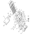
Fig. 1 is an exploded perspective view showing, together with optical
fibers, an optical connector according to an embodiment of this invention;
Fig. 2 is a perspective view showing, together with optical fibers, an
assembly of a first housing and clamp members included in the optical
connector;
Fig. 3 is a perspective view showing the assembly of Fig. 2 together with
optical fibers and a jig attached to end portions of the optical fibers;
Fig. 4 is an enlarged perspective view of the jig and the optical fibers;
Fig. 5 is a perspective view of the optical fibers with polishing waste
attached thereto;
Fig. 6 is a perspective view of first and second housings illustrated in Fig.
1 as seen from a bottom surface;
Fig. 7 is a horizontal sectional bottom view of the optical connector;
Fig. 8 is a vertical sectional view of main parts of the optical connector;
and
Fig. 9 is an enlarged sectional view of a recessed portion of the second
housing illustrated in Fig. 8.
Description of the Preferred Embodiment:
Now, an optical connector according to one embodiment of this invention
will be described with reference to the drawing.
At first referring to Fig. 1, the optical connector comprises a first housing
11, a second housing 21 fitted to the first housing 11, and a plurality of clamp
members 31 mounted to the first housing 11.
The optical connector further comprises a cover member 41 attached to
the first housing 11 to cover a part of the first housing 11, and a fiber protector
member 51 attached to the second housing 21.
The first housing 11 has a main body portion 11a of a generally
rectangular plate-like shape, an aligning portion 11c, and a clamp holding portion
11d. The main body portion 11a has a front end face 11 b on a front side in a
first direction A depicted by an arrow in Fig. 1.
The aligning portion 11c protrudes from the front end face 11b in the first
direction A. The clamp holding portion 11d is formed on a rear side of the main
body portion 11a in the first direction A, i.e., on a front side in a second direction
B opposite to the first direction A.
The main body portion 11a has an upper surface 11e provided with a
fiber confronting surface 11f formed near the aligning portion 11c. The fiber
confronting surface 11f is located in a plane slightly lower in level than the upper
surface 11e and extending in parallel to the upper surface 11e. The clamp
holding portion 11d is a large groove-like portion and has a clamp holding
surface 11g adjacent and contiguous to the fiber confronting surface 11f.
The clamp holding surface 11g is formed adjacent and contiguous to the
fiber confronting surface 11f. The clamp holding surface 11g is located in a
plane lower in level than the fiber confronting surface 11f and extending in
parallel to the fiber confronting surface 11f.
Referring to Fig. 2, the optical connector illustrated in Fig. 1 is
assembled. Referring to Figs. 1 and 2, the aligning portion 11c is provided with
a fiber inserting portion 11j. The fiber inserting portion 11j serves to align and
position a plurality of optical fibers 61 extending over the fiber confronting
surface 11f in the first and the second directions A and B.
The optical fibers 61 have end portions 61a on the front side in the first
direction A. The fiber inserting portion 11j holds the optical fibers 61 with the
end portions 61a protruding from a front end face of the aligning portion 11c.
The fiber inserting portion 11j is provided with a plurality of grooves (not shown)
formed on an inner surface thereof. Each of the grooves has a V-shaped
section and extends in the first and the second directions A and B to position
each individual optical fiber 61. Instead of the grooves, the fiber inserting
portion 11j may be provided with a plurality of narrow holes having a circular
section and extending in the first and the second directions.
The main body portion 11a has a pair of first side surfaces 11k, a pair of
second side surfaces 11m adjacent to the first side surfaces 11k and extending
in the second direction B, and a pair of third side surfaces 11n adjacent to the
second side surfaces 11m and extending in the second direction B.
The first side surfaces 11k are faced to each other in a third direction C
(Fig. 1), i.e., a widthwise direction parallel to the upper surface 11e and
perpendicular to the first and the second directions A and B. Likewise, the
second side surfaces 11m are faced to each other in the third direction C. The
third side surfaces 11n are faced to each other in the third direction C.
The first side surfaces 11k are located on opposite sides of the fiber
confronting surface 11f in the third direction C. The second side surfaces 11m
are located on opposite sides of a junction between the fiber confronting surface
11f and the clamp holding portion 11d to bridge over the fiber confronting surface
11f and the clamp holding portion 11d. The third side surfaces 11n are located
on opposite sides of the clamp holding portion 11d in the third direction C.
A distance between the second side surfaces 11m in the third direction C
is greater than a distance between the first side surfaces 11k in the third direction
C. A distance between the third side surfaces 11n in the third direction C is
greater than a distance between the second side surfaces 11m in the third
direction C.
The aligning portion 11c has an upper surface 11p flush with the upper
surface 11e of the main body portion 11a. At junctions of the first and the
second side surfaces 11k and 11m, a pair of protruding portions 13 protruding in
the third direction C are formed. Each of the protruding portions 13 has a
thickness substantially equal to a thickness of the main body portion 11a.
The second side surfaces 11m are provided with a pair of pin-like
engaging portions 15 protruding in the third direction C. At junctions between
the second and the third side surfaces 11m and 11n, a pair of housing fitting
portions 17 protruding in the third direction C and above the upper surface 11e of
the main body portion 11a are formed. The housing fitting portions 17 are used
to attach the first housing 11 to a mounting object (not shown).
The second housing 21 has a top plate portion 21a, a bottom plate
portion 21b parallel to the top plate portion 21a with a space left therebetween,
and a pair of side plate portions 21c disposed on opposite sides of the upper and
the bottom plate portions 21a and 21b in the third direction C and connecting the
upper and the bottom plate portions 21a and 21b to each other.
The top plate portion 21a is provided with a large cutout portion 21d
formed from a rear end towards a front end in the first direction A (in other words,
from a front end towards a rear end in the second direction B). Each of the side
plate portions 21c is provided with a recessed portion 21e as a cutout formed
from a rear end towards a front end in the first direction A.
The recessed portion 21e has a shape and a size generally coincident
with those of the protruding portion 13 of the first housing 11 so that the
protruding portion 13 is fitted to the recessed portion 21e.
The bottom plate portion 21b of the second housing 21 is provided with
an elongated opening 21g formed at its center and extending in the first and the
second directions A and B. The second housing 21 covers the upper surface
11e of the main body portion 11a, the aligning portion 11c, and the protruding
portions 13.
Each of the top plate portion 21a, the bottom plate portion 21b, and the
side plate portions 21c has a thin plate-like shape. Therefore, the second
housing 21 itself is elastically deformable.
The clamp member 31 has a generally columnar shape of a rectangular
section. In this embodiment, four clamp members 31 are arranged in parallel to
one another. Each of the clamp members 31 holds a plurality of the optical
fibers 61. The optical fibers 61 extend from front end faces of the clamp
members 31 in the first direction A to the outside of the first housing 11.
The cover member 41 has a flat portion 41a and a pair of cover fitting
portions 41b bent from a pair of opposite sides of the flat portion 41a in a
direction perpendicular to the flat plate portion 41a and faced to each other.
Each of the cover fitting portions 41b is inserted between the protruding portion
13 and the housing fitting portion 17 to face the second side surface 11m.
Each of the cover fitting portions 41b is provided with a slit 41c formed
from its lower end towards the flat plate portion 41a. The slit 41c has an
engaged portion 41e formed at an intermediate position in a vertical direction to
receive the engaging portion 15.
The cover member 41 is engaged with and held by the first housing 11
when the engaging portions 15 having a pin-like shape and formed on the
second side surfaces 11m are press-fitted into the slits 41c. At this time, the
engaging portions 15 are press-fitted to reach the engaged portions 41c of the
slits 41c.
The fiber protector member 51 serves to protect the end portions 61a of
the optical fibers 61. The fiber protector member 51 is attached to a front
opening portion 21h of the second housing 21 on the front side in the first
direction A.
After the cover member 41 is attached to the first housing 11, the second
housing 21 is fitted to the first housing 11 so as to cover an outer periphery of the
first housing 11 on the front side in the first direction A. The second housing 21
is provided with a cylindrical cover portion 23 formed on the front side in the first
direction A. The cover portion 23 is formed by the top plate portion 21a, a part
of the bottom plate portion 21b, and parts of the side plate portions 21c. The
cover portion 23 covers the end portions 61a of the optical fibers 61 protruding
from the aligning portion 11c.
Each of the first housing 11, the second housing 21, the clamp members
31, the cover member 41, and the fiber protector member 51 is desirably
produced by molding a resin material. However, some of these components
may be produced using a metal material.
Now, assembling of the optical connector will be described. As
illustrated in Fig. 2, it is assumed that each of the optical fibers 61 protrudes from
the aligning portion 11c in the first direction A by a predetermined length L in a
cantilevered state.
At first, the optical fibers 61 are held by the clamp members 31. The
clamp members 31 holding the optical fibers 61 are fixedly attached to the clamp
holding portion 11d of the first housing 11. For example, the clamp members 31
are fixedly attached to the clamp holding portion 11d by adhesion using an
adhesive agent.
The end portions 61a of the optical fibers 61 protruding through the fiber
inserting portion 11j are protruded in the first direction A. At this time, a
protruding length of the end portion 61a of each of the optical fibers 61
protruding from the aligning portion 11c in the first direction A in a cantilevered
state is not equal to the predetermined length L.
Each of the optical fibers 61 is adapted to be connected to a mating
optical fiber of a mating optical connector (not shown). Prior to connection with
the mating optical fiber of the mating optical connector, the optical fiber 61 is
subjected to a polishing operation which will presently be described.
As illustrated in Figs. 3 and 4, the end portions 61a of the optical fibers
61 are held by a jig 71 comprising a receiving plate 65 having a plurality of V-shaped
grooves 65a and a holding plate 67 of a flat shape. Thereafter, the end
portions 61 a of the optical fibers 61 are slightly protruded in the first direction A
from a front end face of the jig 71 on the front side in the first direction A. Then,
the end portions 61 a of the optical fibers 61 are polished by a polishing
apparatus into the predetermined length L.
Thus, after the clamp members 31 holding the optical fibers 61 are
mounted to the first housing 11, the optical fibers 61 can collectively be polished.
Therefore, the end portions 61a of the optical fibers 61 can be uniformly adjusted
to a common protruding length equal to the predetermined length L. In this
event, the polishing operation can be carried out in the state where the clamp
members 31 are mounted to the first housing 11.
After polishing the end portions 61a of the optical fibers 61, polishing
waste 81 or dust may be adhered to end faces or outer peripheral surfaces of
the end portions 61a of the optical fibers 61 as shown in Fig. 5. In particular,
after the optical fibers 61 are polished, the polishing waste 81 in a powdery state
may be adhered to the end faces or the outer peripheral surfaces of the end
portions 61a of the optical fibers 61. However, the end portions 61 a of the
optical fibers 61 can directly be touched if the jig 71 is removed. Therefore, the
polishing waste 81 can be washed away and removed. Preferably, the
polishing waste 81 or the dust adhered to the end portions 61a of the optical
fibers 61 are washed away and removed by the use of a cleaning cloth
impregnated with alcohol.
After the end portions 61a of the optical fibers 61 are polished and
cleaned, the second housing 21 separate from the first housing 11 is fitted to the
first housing 11. In this event, the first and the second housings 11 and 21 are
locked with each other by a locking structure so as not to be released from each
other.
Referring to Figs. 6 through 9, the locking structure of the first and the
second housings 11 and 12 will be described. The first housing 11 has a
bottom surface 11r provided with a locking portion 18 as a small protrusion. As
shown in Fig. 9 in an enlarged scale, the locking portion 18 is provided with an
inclined surface 18a in a direction intersecting the first and the second directions
A and B. As is obvious from Fig. 9, the inclined surface 18a is inclined in the
first direction A (i.e., leftward in the figure) away from the bottom surface 11r.
The locking portion 18 is formed at a general center of the main body portion 11a
in the vicinity of the aligning portion 11c in correspondence to the opening
portion 21g of the bottom plate portion 21b of the second housing 21.
The second housing 21 is fitted to the first housing 11 from the front side
in the first direction A. In this event, since the first housing 11 has the locking
portion 18, the bottom plate portion 21b of the second housing 21 is pressed
upward by the locking portion 18 to be elastically slightly deformed because the
bottom plate portion 21b has a thin flat shape. When the second housing 21 is
pushed towards the first housing 11 in the second direction B, inner surfaces of
the recessed portions 21e of the second housing 21 are brought into press
contact with the protruding portions 13 of the first housing 11.
At this time, the locking portion 18 enters into the opening portion 21g of
the second housing 21 to be received therein. The bottom plate portion 21b of
the second housing 21 is recovered from elastic deformation to be locked.
In the state where the recessed portions 21e of the second housing 21
are engaged with the protruding portions 13 of the first housing 11, the locking
portion 18 may not be stably brought into contact with a contacting surface 21r of
the opening portion 21g if the inclined surface 18a is not formed. This may
result in occurrence of play between the first and the second housings 11 and
12.
In view of the above, the locking portion 18 of the first housing 11 is
provided with the inclined surface 18a to be brought into contact with the
contacting surface 21 of the opening portion 21g. The inclined surface 18a
serves to absorb the play and assures stable contact even if there is some
dimensional error in these components.
Generally speaking, in case where the end portions 61a of the optical
fibers 61 are protruded frontward from the second housing 21 with the structure
comprising the first and the second housings 11 and 21 as separate components,
an accumulated dimensional error is increased because a greater number of
components are used. In this invention, however, occurrence of play between
the first and the second housings 11 and 21 can be avoided by forming the
inclined surface 18a. Therefore, it is possible to protrude the end portions 61a
of the optical fibers 61 with high accuracy.
Finally, the fiber protector member 51 is inserted into the second
housing 21 in the second direction B from the front side of the second housing
21. The cover member 41 is attached to the first housing 11. Thus, the
assembling is completed.
In this embodiment, since the protruding length of the optical fiber 61
protruding from the first housing 11 can be increased, it is possible to improve
the degree of freedom in fitting the jig 71 upon polishing the optical fiber 61.
Since the optical fibers 61 can be polished in the state where the clamp
members 31 are attached to the first housing 11, It is therefore possible to
suppress the variation in protruding length of the optical fibers 61. Furthermore,
it is possible to easily clean the end face or the outer peripheral surface of the
optical fiber 61 after the optical fiber 61 is polished. By providing the locking
portion 18 with the inclined surface 18a, the first and the second housings 11
and 21 can stably be fitted to each other without leaving any play.
While this invention has thus far been described in conjunction with the
preferred embodiments thereof, it will be readily possible for those skilled in the
art to put this invention into practice in various other manners.