EP1505315A2 - Hydraulic shock absorber - Google Patents
Hydraulic shock absorber Download PDFInfo
- Publication number
- EP1505315A2 EP1505315A2 EP04007229A EP04007229A EP1505315A2 EP 1505315 A2 EP1505315 A2 EP 1505315A2 EP 04007229 A EP04007229 A EP 04007229A EP 04007229 A EP04007229 A EP 04007229A EP 1505315 A2 EP1505315 A2 EP 1505315A2
- Authority
- EP
- European Patent Office
- Prior art keywords
- valve
- piston
- chamber
- piston rod
- damping force
- Prior art date
- Legal status (The legal status is an assumption and is not a legal conclusion. Google has not performed a legal analysis and makes no representation as to the accuracy of the status listed.)
- Granted
Links
Images


Classifications
-
- F—MECHANICAL ENGINEERING; LIGHTING; HEATING; WEAPONS; BLASTING
- F16—ENGINEERING ELEMENTS AND UNITS; GENERAL MEASURES FOR PRODUCING AND MAINTAINING EFFECTIVE FUNCTIONING OF MACHINES OR INSTALLATIONS; THERMAL INSULATION IN GENERAL
- F16F—SPRINGS; SHOCK-ABSORBERS; MEANS FOR DAMPING VIBRATION
- F16F9/00—Springs, vibration-dampers, shock-absorbers, or similarly-constructed movement-dampers using a fluid or the equivalent as damping medium
- F16F9/32—Details
- F16F9/44—Means on or in the damper for manual or non-automatic adjustment; such means combined with temperature correction
- F16F9/46—Means on or in the damper for manual or non-automatic adjustment; such means combined with temperature correction allowing control from a distance, i.e. location of means for control input being remote from site of valves, e.g. on damper external wall
- F16F9/464—Control of valve bias or pre-stress, e.g. electromagnetically
-
- F—MECHANICAL ENGINEERING; LIGHTING; HEATING; WEAPONS; BLASTING
- F16—ENGINEERING ELEMENTS AND UNITS; GENERAL MEASURES FOR PRODUCING AND MAINTAINING EFFECTIVE FUNCTIONING OF MACHINES OR INSTALLATIONS; THERMAL INSULATION IN GENERAL
- F16F—SPRINGS; SHOCK-ABSORBERS; MEANS FOR DAMPING VIBRATION
- F16F9/00—Springs, vibration-dampers, shock-absorbers, or similarly-constructed movement-dampers using a fluid or the equivalent as damping medium
- F16F9/06—Springs, vibration-dampers, shock-absorbers, or similarly-constructed movement-dampers using a fluid or the equivalent as damping medium using both gas and liquid
- F16F9/061—Mono-tubular units
-
- F—MECHANICAL ENGINEERING; LIGHTING; HEATING; WEAPONS; BLASTING
- F16—ENGINEERING ELEMENTS AND UNITS; GENERAL MEASURES FOR PRODUCING AND MAINTAINING EFFECTIVE FUNCTIONING OF MACHINES OR INSTALLATIONS; THERMAL INSULATION IN GENERAL
- F16F—SPRINGS; SHOCK-ABSORBERS; MEANS FOR DAMPING VIBRATION
- F16F9/00—Springs, vibration-dampers, shock-absorbers, or similarly-constructed movement-dampers using a fluid or the equivalent as damping medium
- F16F9/06—Springs, vibration-dampers, shock-absorbers, or similarly-constructed movement-dampers using a fluid or the equivalent as damping medium using both gas and liquid
- F16F9/062—Bi-tubular units
Definitions
- the present invention relates to a hydraulic shock absorber for an automobile or a motorcycle.
- the Japanese Patent Application Laid-Open No. H3-292429 discloses a hydraulic shock absorber, wherein a piston rod side chamber and a piston side chamber are sectioned in a dumper cylinder by a piston provided in a piston rod inserted slidably in the dumper cylinder, the piston being provided with a pressure side valve and a pressure side damping force adjusting device.
- a partition wall member for sectioning the piston side chamber and a reservoir chamber is provided with the pressure side valve and the pressure side damping force adjusting device.
- the pressure side damping force is generated by the pressure side damping force adjusting device of the piston with respect to the operating oil substituted and flowing from the piston side chamber to the piston rod side chamber, and by the pressure side damping force adjusting device of the partition member with respect to the operating oil corresponding to the entrance volume of the piston rod into the damper cylinder.
- the pressure side damping force is generated by the pressure side valve of the piston with respect to the operating oil substituted and flowing from the piston side chamber to the piston rod side chamber, and by the pressure side valve of the partition wall member with respect to the operating oil corresponding to the entrance volume of the piston rod.
- the pressure of the piston rod side chamber in the damper cylinder is:
- the Japanese Patent Publication No. 2,820,276 discloses a hydraulic shock absorber comprising pressure side valves including a first damping valve and a second damping valve provided in a pressure side damping valve of a piston and a base (partition member), wherein a second check valve provided in a check channel of a base is opened so as to supply a fluid from a reservoir chamber provided above the base to a piston rod side chamber in the case the aperture of the pressure side damping valve of the piston is so large that the lower chamber (piston rod side chamber) in the cylinder tube is in the negative pressure in the compression process.
- the second check valve for supplying a fluid from the reservoir chamber to the piston rod side chamber via the outer side chamber in the case the aperture of the pressure side damping valve of the piston is so large that the lower chamber (piston rod side chamber) in the cylinder tube is at a negative pressure, a valve adjusting device for adjusting the injection valve opening pressure of the second check valve provided in the partition member from the outside is not provided.
- an object of the present invention is to provide a hydraulic shock absorber, capable of avoiding the negative pressure of the piston rod side chamber without changing the setting (adjusting amount) of the pressure side damping force adjusting device, or the setting (valve specification, or the like) of the spring characteristics of the pressure side valve, and capable of adjusting the pressure side damping force or the stretch side damping force characteristics by adjusting the pressure of the piston rod side chamber.
- a hydraulic shock absorber comprising a piston provided in the top end part of a piston rod inserted slidably in a damper cylinder, a piston rod side chamber for storing the piston rod and a piston side chamber not storing the piston rod defined by the piston in the damper cylinder, a reservoir chamber separated from the piston side chamber not storing the piston rod by a partition wall member, and pressure side valves for generating the damping force at the time of compression provided each in the piston and the partition wall member.
- a path for communication between the reservoir chamber and the piston rod side chamber is formed, a blow valve is provided in the path, to be opened at the time the differential pressure between the reservoir chamber and the piston rod side chamber reaches a predetermined value, for allowing oil to flow from the reservoir chamber to the piston rod side chamber, and a blow valve adjusting device for operating the valve opening pressure of the blow valve from outside is provided.
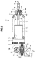
- a hydraulic shock absorber 10 for an automobile or a motorcycle comprises a damper case 11 having an outer cylinder 11A, with a damper cylinder 11B provided upright in the outer cylinder 11A of the damper case 11. Then, the hydraulic shock absorber 10 has a hollow piston rod 12 inserted in the damper cylinder 11B of the damper case 11, and a suspension spring 13 provided on the outer circumference side of the outer cylinder 11A of the damper case 11 and the piston rod 12.
- the outer cylinder 11A of the damper case 11 comprises an automobile or motorcycle body side mounting member 14, and the piston rod 12 comprises a wheel side mounting member 15.
- a pneumatic jack 16 is fixed on the outer circumference part of the damper cylinder 11B so that a spring receipt 17 provided in a plunger 16A of the pneumatic jack 16 can be supported by a spring receipt supporting ring 18 attached on the housing 16B of the pneumatic jack 16.
- a spring receipt 19 is provided in the wheel side mounting member 15 mounted on the piston rod 12.
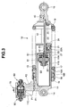
- the outer cylinder 11A and the damper cylinder 11B of the damper case 11 comprise a rod guide 21 through which the piston rod 12 is inserted and fitted fluidically tightly.
- the rod guide 21 accommodates the piston rod 12 fluidically tightly and slidably in the inner diameter part comprising an oil seal 22, an oil seal press 22A, and a bush 23.
- the damper case 11 comprises a bumper stopper 24 on the outer side end of the outer cylinder 11A so that the most compression stroke can be limited by crashing a pressure side bump rubber 25 provided in the spring receipt 19 around the piston rod 12 with the bumper stopper 24 at the time of being mostly compressed.
- the piston rod 12 comprises a stretch side bump spring 26 in the piston holder 12A inserted in the damper cylinder 11B so that the most stretched stroke can be limited by crashing the bump spring 26 with the oil seal press 22A of the rod guide 21 at the time of being mostly stretched.
- the hydraulic shock absorber 10 comprises a piston valve device 30, a base valve device 50, and a blow valve device 80.
- the hydraulic shock absorber 10 controls the stretch and contraction oscillation of the damper case 11 and the piston rod 12 accompanied by the absorption of the impact force by the suspension spring 13 by the damping force generated by the valve devices 30, 50, 80.
- the piston valve device 30 comprises a sub piston 31, a pressure side sub valve 32, a valve stopper 33, a pressure side valve 34, a main piston 35, a stretch side valve 36, and a valve stopper 37 mounted successively on a piston holder 12A provided in the top end part of a piston rod 12 inserted through a dumper cylinder 11B of a dumber case 11, with these elements fastened by a nut 38.
- the main piston 35 slides inside the dumper cylinder 11B so as to divide the inside of the dumper cylinder 11B into a piston rod side chamber S1 storing the piston rod 12, and a piston side chamber S2 not storing the piston rod 12.
- the main piston 35 comprises a pressure side channel 35A comprising the pressure side valve 34 having a large number of plate like valve pieces laminated, for allowing communication between the piston rod side chamber S1 and the piston side chamber S2, and a stretch side channel 35B comprising the stretch side valve 36 having a large number of plate like valve pieces laminated, for allowing communication between the piston rod side chamber S1 and the piston side chamber S2.
- the piston valve device 30 comprises a first pressure side damping force adjusting device 40.
- the first pressure side damping force adjusting device 40 is provided with a bypass path 41 with one end opened in the piston side chamber S2, and the other end opened in the piston rod side chamber S1 via the channel 31A of the sub piston 31, and the pressure side sub valve 32 in the piston rod 12.
- the bypass path 41 is provided parallel with the pressure side valve 34 (pressure side channel 35A) and the stretch side valve 36 (stretch side channel 35B).
- the first pressure side damping force adjusting device 40 is provided with a damping force adjusting rod 42 for adjusting the channel area of the bypass path 41 in the piston rod 12.
- the damping force adjusting rod 42 is moved reciprocally in the piston rod 12 by an adjuster device 43 provided in the wheel side mounting member 15 such that the channel area of the bypass path 41 is adjusted by the needle valve 42A on the top end.
- the valve is opened at the time the pressure of the piston side chamber S2 with the bypass path 41 opened reaches or exceeds a certain value.
- the adjuster device (FIG. 2) operates the adjuster rod 45 inserted in the adjuster holder 44 pressed and fixed in the wheel side mounting member 15 for the outside rotation, laterally moves the slide cam 46 attached on the adjuster rod 45 under the guidance of the guide bolt 47, and reciprocally moves the damping force adjusting rod 42 bearing against the cam surface of the cam 46 in the vertical direction of the piston rod 12.
- the adjuster rod 45 engages a ball 48B forced by a set spring 48A successively with engaging recess parts provided at a plurality of positions in the circumferential direction in the inner circumference of the adjuster holder 44 so as to be set at any rotation operation position.
- the oil in the piston side chamber S2 flows from the bypass path 41 comprising the first pressure side damping force adjusting device 40 to the piston rod side chamber S1 so as to generate the pressure side damping force (to be adjusted by the adjuster device 43) generated by the aperture resistance of the needle valve 42A of the damping force adjusting rod 42, and the pressure side damping force derived from the flow resistance in the gap formed by the deflected deformed part of the pressure side sub valve 32 with respect to the sub piston 31.
- the oil in the piston side chamber S2 deflects and deforms the pressure side valve 34 so as to push and open the same for allowing oil to flow into the piston rod side chamber S1 so that the pressure side damping force is generated, derived from the flow resistance in the gap formed by the deflected and deformed part of the pressure side valve 34 with respect to the main piston 35.
- the oil in the piston rod side chamber S1 deflects and deforms the stretch side valve 36 so as to push and open the same for allowing oil to flow into the piston side chamber S2 so that the stretch side damping force is derived from the flow resistance in the gap formed by the deflected and deformed part of the stretch side valve 36 with respect to the main piston 35.
- the shock absorber 10 comprises a sub tank 11C provided integrally with the outer cylinder 11A of the damper case 11, with a reservoir chamber S3 provided inside the sub tank 11C.
- the sub tank 11C has an inside sealed by the cap 51 and divided by a diaphragm 52 (it may also be a free piston) into the reservoir chamber S3 and a pressuring gas chamber 53.
- the cap 51 is provided with a gas sealing valve 54.
- the hydraulic shock absorber 10 comprises a first path P1 for communication between the piston side chamber S2 and the reservoir chamber S3 respectively in the outer cylinder 11A and the sub tank 11C of the damper case 11via the base valve device 50.
- the base valve device 50 comprises a partition wall member 55 and a valve housing 56 fluidically tightly mounted in the first path P1 formed in the sub tank 11C.
- the partition wall member 55 and the valve housing 56 are fixed by a plug bolt 57 to be attached on the sub tank 11C.
- the partition wall member 55 separates the piston side chamber S2 from the reservoir chamber S3.
- a channel 55A is formed in the partition wall member 55.
- a bypass forming bolt 58 is fixed by a nut 59 in the central part of the partition wall member 55, with a pressure side valve 60 for opening the channel 55A at the time of compression, and a stretch side valve (check valve) 61 for communication through channel 55A at the time of stretch provided around the central part of the bypass forming bolt 58.
- the pressure side valve 60 comprises a large number of plate like valve pieces laminated, is clamped and supported between the partition wall member 55 and the bypass forming bolt 58 via a valve stopper 60A.
- the stretch side valve 61 is biased by a valve spring 61A supported by its rear surface by the partition wall member 55 so as to be seated on a valve receipt 62 clamped by the partition wall member 55 and the valve housing 56.
- the pressure side valve 60 is seated on the flat surface of the stretch side valve 61 seated on the valve receipt 62.
- the base valve device 50 comprises a second pressure side damping force adjusting device 70.
- the second pressure side damping force adjusting device 70 has a bypass path 71 for communication between the piston side chamber S2 and the reservoir chamber S3 provided in the bypass forming bolt 58.
- the bypass path 71 is provided parallel with the pressure side valve 60 and the stretch side valve 61 (channel 55A).
- the second pressure side damping force adjusting device 70 has a rod supporting member 72 pressed in and fixed to the center of the plug bolt 57 fitted fluidically tightly to the top end cup part 58A of the bypass forming bolt 58, and comprises a damping force adjusting rod 73 to be attached onto a rod supporting member 72 for adjusting the channel area of the bypass path 71.
- the damping force adjusting rod 73 is moved reciprocally in the rod supporting member 72 according to the outside rotation operation of an adjuster rod 74 provided through the plug bolt 57 so that the channel area of the bypass path 71 can be adjusted by the top end needle valve 73A.
- the bypass path 71 allows communication with the first path P1 on the reservoir chamber S3 side via the channel 58B provided in the top end cup part 58A of the bypass forming bolt 58.
- the adjuster rod 74 is rotatable within the plug bolt 57 by the knob 75 fixed on the outer side end of said plug bolt 57 so that a top end projection piece 74A of the adjuster rod 74 fixed in rotation on the base end recess part of the damping force adjusting rod 73 rotates said rod 73 in the same direction and moves the top end needle valve 73A longitudinally.
- Balls 76B forced by set springs 76A are mounted in the plug bolt 57 on its outer side end face for engaging successively with engaging recess parts provided at a plurality of positions in the circumference direction of the knob 75 inner side end face so that the adjuster rod 74 can be set at any rotation operation position.
- the oil corresponding to the entrance volume of the piston rod 12 into the damper cylinder 11B flows from the piston side chamber S2 to the reservoir chamber S3 via the bypass path 71 comprising the second pressure side damping force adjusting device 70 so as to generate the pressure side damping force (to be adjusted by the adjuster rod 74) generated by the aperture resistance of the needle valve 73A of the damping force adjusting rod 73.
- the oil of the piston side chamber S2 deflects and deforms the pressure side valve 60 so as to push and open the same for flowing into the reservoir chamber S3, and the deflected and deformed part of the pressure side valve 60 is separated from the flat surface of the stretch side valve 61 so as to generate the pressure side damping force derived from the flow resistance of the generated gap.
- the oil corresponding to the withdrawal volume of the piston rod 12 from the damper cylinder 11B flows from the reservoir chamber S3 to the piston side chamber S2 via the bypass path 71, and the oil of the reservoir chamber S3 opens the stretch side valve 61 so as to be supplied to the piston side chamber S2.
- the hydraulic shock absorber 10 comprises an outer side chamber 81 communicating with the piston rod side chamber S1 via the oil hole 27 formed in the damper cylinder 11B, said chamber 81 being defined between the outer cylinder 11A and the damper cylinder 11B of the damper case 11.
- the hydraulic shock absorber 10 is provided with a second path P2 for communication between the reservoir chamber S3 and the outer side chamber 81 in the outer cylinder 11A of the damper case 11.
- the blow valve device 80 is provided in the second path P2 formed in the sub tank 11C.
- the blow valve device 80 has a valve sheet 82 fluidically tightly mounted in the middle part of the second path P2 formed in the sub tank 11C, and the valve sheet 82 is fixed by a plug bolt 91, or the like of the stretch side damping force adjusting device 90 to be described later.
- the valve sheet 82 separates the piston rod side chamber S1 and the reservoir chamber S3 communicating with each other via the outer side chamber 81.
- a channel 82A is formed in the valve sheet 82, and a plate like blow valve 83 for opening or closing the channel 82A is biased and seated by the valve spring 83A.
- the blow valve 83 is opened at the time the differential pressure between the piston rod side chamber S1 and the reservoir chamber S3 reaches a predetermined value so as to allow the oil to flow from the reservoir chamber S3 to the piston rod side chamber S1.
- the solid line arrow represents the oil flow in the compression process
- the broken line arrow represents the oil flow at the time the blow valve 83 is opened.
- the blow valve device 80 comprises a blow valve adjusting device 84.
- the blow valve adjusting device 84 has a spring force adjusting rod 86 attached on the plug bolt 85 screwed on one end side of the sub tank 11C, and supports the rear surface of the valve spring 83A by the washer 86B supported by the flange 86A of the spring force adjusting rod 86.
- the spring force adjusting rod 86 is moved reciprocally according to the rotation operation from outside of an adjuster rod 87 provided through the plug bolt 85, so as to adjust the spring force of the valve spring 83A, and thus to adjust the valve opening pressure of the blow valve 83.
- the adjuster rod 87 is secured to a knob 88 fixed on the outer side end, and engaging balls 89B forced by set springs 89A stored in the outer side end face of the plug bolt 85 successively with engaging recess parts provided in a plurality of positions on the circumference of the inner side end face of the knob 88 so as to set the adjuster rod 87 at any rotation operation position.
- the top end stopper surface 86C of the spring force adjusting rod 86 is crashed against the end face of the bypass forming bolt 92 of the stretch side damping force adjusting device 90 to be described later at the time of the maximum compression of the valve spring 83A by the adjuster rod 87, and it comprises a slot 86D for preventing closure of the bypass path 92A.
- the blow' valve device 80 comprises a stretch side damping force adjusting device 90.
- the stretch side damping force adjusting device 90 has a plug bolt 91 attached on the other end side (side opposite to the plug bolt 85) of the sub tank 11C.
- the bypass forming bolt 92 is provided with a bypass path 92A opened on the piston rod side chamber S1 side
- the sub valve sheet 93 is provided with a channel 93A to be connected in series with the bypass path 92A and opened on the reservoir chamber S3 side.
- the bypass path 92A and the channel 93A are provided parallel with the blow valve 83 (channel 82A of the valve sheet 82).
- the stretch side damping force adjusting device 90 has a damping force adjusting rod 97 for adjusting the channel area of the bypass path 92A in the bypass forming bolt 92.
- the damping force adjusting rod 97 is moved reciprocally in the bypass forming bolt 92 according to the outer side rotation operation of an adjuster rod 98 provided through the plug bolt 91.
- the channel area of the bypass path 92A is adjusted by the top end needle valve 97A.
- the stretch side sub valve 94 is backed up by the valve stopper 95 via a plurality of shims, covers the channel 93A from the reservoir chamber S3 side, and opens at the time the pressure of the piston rod side chamber S1 reaches or exceeds a certain value.
- the adjuster rod 98 is rotated within the plug bolt 91 by a knob 99 fixed on the outer side end of said plug bolt 91 so that a top end projection piece 98A of the adjuster rod 98 is fixed in rotation on the base end recess part of the damping force adjusting rod 97 and rotates said rod 97 in the same direction, thus moving the top end needle valve 97A longitudinally.
- a knob 99 fixed on the outer side end of said plug bolt 91 so that a top end projection piece 98A of the adjuster rod 98 is fixed in rotation on the base end recess part of the damping force adjusting rod 97 and rotates said rod 97 in the same direction, thus moving the top end needle valve 97A longitudinally.
- the blow valve 83 is opened so as to avoid a negative pressure in the piston rod side chamber S1.
- the valve opening pressure of the blow valve 83 can be adjusted by the blow valve adjusting device 84.
- the oil of the piston side chamber S1 passes through the bypass path 92A comprising the stretch side damping force adjusting device 90, deflects and deforms the stretch side sub valve 94 so as to push and opens the same, and flows into the reservoir chamber S3.
- the stretch side damping force (to be adjusted by the adjuster rod 98) is generated by the aperture resistance of the needle valve 97A of the damping force adjusting rod 97, and the stretch side damping force is derived from the flow resistance of the gap formed between the deflected and deformed part of the stretch side sub valve 94 and the sub valve sheet 93.
- the stretch side damping force adjusting device 90 can be omitted.
- the hydraulic shock absorber 10 executes the damping operation as follows.
- the blow vale 83 is opened at the time the differential pressure between the piston rod side chamber S1 and the reservoir chamber S3 reaches a predetermined value, and the oil of the reservoir chamber S3 flows to the piston rod side chamber S1 so as to avoid a negative pressure in the piston rod side chamber S1.
- the stretching and contraction oscillation of the hydraulic shock absorber 10 can be controlled.
- the hydraulic shock absorber 100 comprises a piston 103 on the top end part of a piston rod 102 inserted fluidically tightly and slidably in a single cylinder type damper cylinder 101, and defining a piston rod side chamber S1 and a piston side chamber S2.
- a partition wall member 104 is fluidically tightly mounted on the side opposite to the side with the piston rod 102 inside the damper cylinder 101.
- a reservoir chamber S3 is separated by a partition wall member 104 from the piston side chamber S2.
- a pressuring gas chamber 106 separated from the reservoir chamber S3 by a diaphragm 105 is provided inside the damper cylinder 101.
- the hydraulic shock absorber 100 comprises a piston valve device 110, a base valve device 120, and a blow valve device 130.
- the piston valve device 110 comprises, in the piston 103, a pressure side valve 111 for generating the damping force at the time of compression, and a stretch side valve 112 for generating the damping force at the time of stretch.
- the piston valve device 110 is provided with a bypass path 113 provided parallel with the pressure side valve 111 disposed in the piston 103, and comprises a first pressuring side damping force adjusting device 114 for adjusting the aperture area of the bypass path 113.
- the base valve device 120 comprises, in the partition wall member 104, a pressure side valve 121 for generating the damping force at the time of compression, and a stretch side check valve 122 for allowing the flow at the time of stretch.
- the base valve device 120 is provided with a bypass path 123 provided parallel with the pressure side valve 121 disposed in the partition wall member 104, and comprises a second pressure side damping force adjusting device 124 for adjusting the aperture area of the bypass path 123.
- the blow valve device 130 is provided with a valve sheet 132 in a path 131 for communication between the reservoir chamber S3 and the piston rod side chamber S1, and comprises a blow valve 133 in the valve sheet 132.
- the blow valve 133 is opened at the time the differential pressure between the reservoir chamber S3 and the piston rod side chamber S1 reaches a predetermined value so as to allow the flow from the reservoir chamber S3 to the piston rod side chamber S1.
- the blow valve 133 comprises a blow valve adjusting device 134 additionally so that the blow valve adjusting device 134 allows adjustment of the valve opening pressure of the blow valve 133 from outside.
- the blow valve device 130 is provided with a bypass path 135 provided parallel with the blow valve 133 in the valve sheet 132, and comprises a stretch side damping force adjusting device 136 for adjusting the aperture area of the bypass path 135.
- the stretch side damping force adjusting device 136 comprises a stretch side valve 137 to be opened at the time the pressure of the piston rod side chamber S1 reaches or exceeds a certain value in series with the stretch side damping force adjusting device 136.
Abstract
Description
- The present invention relates to a hydraulic shock absorber for an automobile or a motorcycle.
- The Japanese Patent Application Laid-Open No. H3-292429 discloses a hydraulic shock absorber, wherein a piston rod side chamber and a piston side chamber are sectioned in a dumper cylinder by a piston provided in a piston rod inserted slidably in the dumper cylinder, the piston being provided with a pressure side valve and a pressure side damping force adjusting device. A partition wall member for sectioning the piston side chamber and a reservoir chamber is provided with the pressure side valve and the pressure side damping force adjusting device.
- According to a compression process of the hydraulic shock absorber, at a low speed range of the piston speed, the pressure side damping force is generated by the pressure side damping force adjusting device of the piston with respect to the operating oil substituted and flowing from the piston side chamber to the piston rod side chamber, and by the pressure side damping force adjusting device of the partition member with respect to the operating oil corresponding to the entrance volume of the piston rod into the damper cylinder. Moreover, at a medium and high speed range of the piston speed, the pressure side damping force is generated by the pressure side valve of the piston with respect to the operating oil substituted and flowing from the piston side chamber to the piston rod side chamber, and by the pressure side valve of the partition wall member with respect to the operating oil corresponding to the entrance volume of the piston rod. Thereby, the high pressure side damping force can be generated in all the speed range of the piston speed, and furthermore, the pressure side damping force adjusting range can be made larger in the low speed range.
- Then, according to this hydraulic shock absorber, in the stroke range most frequently used, in the low speed range of the piston speed, the differential pressure of the piston side chamber and the piston rod side chamber generated by the pressure side damping force adjusting device of the piston, and the differential pressure of the piston side chamber and the reservoir chamber generated by the pressure side damping force adjusting device of the partition member are adjusted so as to be equal. Moreover, in the medium and high speed range of the piston speed, the differential pressure of the piston side chamber and the piston rod side chamber generated by the pressure side valve of the piston, and the differential pressure of the piston side chamber and the reservoir chamber generated by the pressure side valve of the partition member are made to be equal. Thereby, generation of the negative pressure is prevented in the piston rod side chamber in each speed range of the compression process.
- According to this hydraulic shock absorber, the pressure of the piston rod side chamber in the damper cylinder is:
- (a) determined by the setting of the pressure side damping force adjusting device of the piston (the spring load of the coil spring for forcing the poppet valve in the case of a poppet valve, the valve opening degree in the case of a needle valve, or the like), and the setting of the pressure side damping force adjusting device of the partition member in the low speed range of the piston speed; and
- (b) determined by the spring characteristics (the spring constant and the initial load of the pressure side valve) of the pressure side valve of the piston and the pressure side valve of the partition member in the medium and high speed range of the piston speed.
-
- As a result, in order to prevent generation of the negative pressure in the piston rod side chamber, in the low speed range of the piston speed, it is required to adjust the pressure side damping force adjusting device of the piston and/or the partition member is required, and furthermore, in the medium and high speed range, it is required to alter the spring characteristics (change to the valve having different spring characteristics, of the like) of the pressure side valve and/or the partition member of the piston. Therefore, a problem arises in that time is needed for the damping force adjustment for the piston and the partition member, or the valve changing, and furthermore, accompanied by the adjustment of the pressure side damping force adjusting device or the change of the valve, a problem arises in that the pressure side damping force generated by the piston or the partition member changes as well.
- The Japanese Patent Publication No. 2,820,276 discloses a hydraulic shock absorber comprising pressure side valves including a first damping valve and a second damping valve provided in a pressure side damping valve of a piston and a base (partition member), wherein a second check valve provided in a check channel of a base is opened so as to supply a fluid from a reservoir chamber provided above the base to a piston rod side chamber in the case the aperture of the pressure side damping valve of the piston is so large that the lower chamber (piston rod side chamber) in the cylinder tube is in the negative pressure in the compression process.
- According to this hydraulic shock absorber, the second check valve for supplying a fluid from the reservoir chamber to the piston rod side chamber via the outer side chamber in the case the aperture of the pressure side damping valve of the piston is so large that the lower chamber (piston rod side chamber) in the cylinder tube is at a negative pressure, a valve adjusting device for adjusting the injection valve opening pressure of the second check valve provided in the partition member from the outside is not provided. Therefore, there is no disclosure of any technological items for preventing the generation of the negative pressure in the piston rod side chamber without the need of changing the spring characteristics (valve specification) of the pressure side valves of the first damping valve and the second damping valve provided in the pressure side damping valve and the base (partition member) of the piston (piston), adjusting the pressure side damping force by adjusting the pressure of the piston rod side chamber, or adjusting the stretch side damping force characteristics.
- Accordingly, an object of the present invention is to provide a hydraulic shock absorber, capable of avoiding the negative pressure of the piston rod side chamber without changing the setting (adjusting amount) of the pressure side damping force adjusting device, or the setting (valve specification, or the like) of the spring characteristics of the pressure side valve, and capable of adjusting the pressure side damping force or the stretch side damping force characteristics by adjusting the pressure of the piston rod side chamber.
- According to the present invention, there is disclosed a hydraulic shock absorber comprising a piston provided in the top end part of a piston rod inserted slidably in a damper cylinder, a piston rod side chamber for storing the piston rod and a piston side chamber not storing the piston rod defined by the piston in the damper cylinder, a reservoir chamber separated from the piston side chamber not storing the piston rod by a partition wall member, and pressure side valves for generating the damping force at the time of compression provided each in the piston and the partition wall member.
- A path for communication between the reservoir chamber and the piston rod side chamber is formed, a blow valve is provided in the path, to be opened at the time the differential pressure between the reservoir chamber and the piston rod side chamber reaches a predetermined value, for allowing oil to flow from the reservoir chamber to the piston rod side chamber, and a blow valve adjusting device for operating the valve opening pressure of the blow valve from outside is provided.
- The present invention will be more fully understood from the detailed description given below and from the accompanying drawings which should not be taken to be a limitation on the invention, but are for explanation and understanding only.
- FIG. 1 is a schematic diagram showing a hydraulic shock absorber according to a first embodiment;
- FIG. 2 is a cross sectional view showing a hydraulic shock absorber;
- FIG. 3 is a cross sectional view taken along the line III-III of FIG. 2;
- FIG. 4 is a cross sectional view taken along the line IV-IV of FIG. 2;
- FIG. 5 is a cross sectional view showing a piston valve device;
- FIG. 6 is a cross sectional view showing a base valve device;
- FIG. 7 is a cross sectional view showing a blow valve device; and
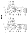
- FIG. 8 is a schematic diagram showing a hydraulic shock absorber according to a second embodiment.
-
- As shown in FIGS. 1 to 4, a hydraulic shock absorber 10 for an automobile or a motorcycle comprises a
damper case 11 having anouter cylinder 11A, with adamper cylinder 11B provided upright in theouter cylinder 11A of thedamper case 11. Then, the hydraulic shock absorber 10 has ahollow piston rod 12 inserted in thedamper cylinder 11B of thedamper case 11, and asuspension spring 13 provided on the outer circumference side of theouter cylinder 11A of thedamper case 11 and thepiston rod 12. - The
outer cylinder 11A of thedamper case 11 comprises an automobile or motorcycle bodyside mounting member 14, and thepiston rod 12 comprises a wheelside mounting member 15. Apneumatic jack 16 is fixed on the outer circumference part of thedamper cylinder 11B so that aspring receipt 17 provided in aplunger 16A of thepneumatic jack 16 can be supported by a springreceipt supporting ring 18 attached on thehousing 16B of thepneumatic jack 16. Aspring receipt 19 is provided in the wheelside mounting member 15 mounted on thepiston rod 12. By providing thesuspension spring 13 between thespring receipt 17 and thespring receipt 19, and displacing the mounting position of thespring receipt 17 by thepneumatic jack 16 and the springreceipt supporting ring 18, the setting height of thesuspension spring 13 can be adjusted. The spring force of thespring 13 absorbs the impact force applied on the automobile from the road surface. - The
outer cylinder 11A and thedamper cylinder 11B of thedamper case 11 comprise arod guide 21 through which thepiston rod 12 is inserted and fitted fluidically tightly. Therod guide 21 accommodates thepiston rod 12 fluidically tightly and slidably in the inner diameter part comprising anoil seal 22, anoil seal press 22A, and abush 23. Thedamper case 11 comprises abumper stopper 24 on the outer side end of theouter cylinder 11A so that the most compression stroke can be limited by crashing a pressureside bump rubber 25 provided in thespring receipt 19 around thepiston rod 12 with thebumper stopper 24 at the time of being mostly compressed. Moreover, thepiston rod 12 comprises a stretchside bump spring 26 in thepiston holder 12A inserted in thedamper cylinder 11B so that the most stretched stroke can be limited by crashing thebump spring 26 with theoil seal press 22A of therod guide 21 at the time of being mostly stretched. - As shown in FIG. 1, the
hydraulic shock absorber 10 comprises apiston valve device 30, abase valve device 50, and ablow valve device 80. The hydraulic shock absorber 10 controls the stretch and contraction oscillation of thedamper case 11 and thepiston rod 12 accompanied by the absorption of the impact force by thesuspension spring 13 by the damping force generated by thevalve devices - As shown in FIGS. 1, 3, 5, the
piston valve device 30 comprises asub piston 31, a pressureside sub valve 32, avalve stopper 33, apressure side valve 34, amain piston 35, astretch side valve 36, and avalve stopper 37 mounted successively on apiston holder 12A provided in the top end part of apiston rod 12 inserted through adumper cylinder 11B of adumber case 11, with these elements fastened by anut 38. - The
main piston 35 slides inside thedumper cylinder 11B so as to divide the inside of thedumper cylinder 11B into a piston rod side chamber S1 storing thepiston rod 12, and a piston side chamber S2 not storing thepiston rod 12. Themain piston 35 comprises apressure side channel 35A comprising thepressure side valve 34 having a large number of plate like valve pieces laminated, for allowing communication between the piston rod side chamber S1 and the piston side chamber S2, and astretch side channel 35B comprising thestretch side valve 36 having a large number of plate like valve pieces laminated, for allowing communication between the piston rod side chamber S1 and the piston side chamber S2. - The
piston valve device 30 comprises a first pressure side dampingforce adjusting device 40. - As shown in FIGS. 1 to 3 and 5, the first pressure side damping
force adjusting device 40 is provided with abypass path 41 with one end opened in the piston side chamber S2, and the other end opened in the piston rod side chamber S1 via thechannel 31A of thesub piston 31, and the pressureside sub valve 32 in thepiston rod 12. Thebypass path 41 is provided parallel with the pressure side valve 34 (pressure side channel 35A) and the stretch side valve 36 (stretch side channel 35B). - The first pressure side damping
force adjusting device 40 is provided with a dampingforce adjusting rod 42 for adjusting the channel area of thebypass path 41 in thepiston rod 12. The dampingforce adjusting rod 42 is moved reciprocally in thepiston rod 12 by anadjuster device 43 provided in the wheelside mounting member 15 such that the channel area of thebypass path 41 is adjusted by theneedle valve 42A on the top end. When the pressureside sub valve 32 is backed up by thevalve stopper 33 via a shim so as to cover thechannel 31A of the sub piston 31 (the opening part to the piston rod side chamber S1 of thebypass path 41 on the downstream side of theneedle valve 42A of the first pressure side damping force adjusting device 40) , the valve is opened at the time the pressure of the piston side chamber S2 with thebypass path 41 opened reaches or exceeds a certain value. - The adjuster device (FIG. 2) operates the
adjuster rod 45 inserted in theadjuster holder 44 pressed and fixed in the wheelside mounting member 15 for the outside rotation, laterally moves theslide cam 46 attached on theadjuster rod 45 under the guidance of theguide bolt 47, and reciprocally moves the dampingforce adjusting rod 42 bearing against the cam surface of thecam 46 in the vertical direction of thepiston rod 12. Theadjuster rod 45 engages aball 48B forced by aset spring 48A successively with engaging recess parts provided at a plurality of positions in the circumferential direction in the inner circumference of theadjuster holder 44 so as to be set at any rotation operation position. - Therefore, in the low speed range in the compression process of the hydraulic shock absorber 10 the oil in the piston side chamber S2 flows from the
bypass path 41 comprising the first pressure side dampingforce adjusting device 40 to the piston rod side chamber S1 so as to generate the pressure side damping force (to be adjusted by the adjuster device 43) generated by the aperture resistance of theneedle valve 42A of the dampingforce adjusting rod 42, and the pressure side damping force derived from the flow resistance in the gap formed by the deflected deformed part of the pressureside sub valve 32 with respect to thesub piston 31. Moreover, in the medium and high speed range, the oil in the piston side chamber S2 deflects and deforms thepressure side valve 34 so as to push and open the same for allowing oil to flow into the piston rod side chamber S1 so that the pressure side damping force is generated, derived from the flow resistance in the gap formed by the deflected and deformed part of thepressure side valve 34 with respect to themain piston 35. - In the stretch process of the hydraulic shock absorber 10, the oil in the piston rod side chamber S1 deflects and deforms the
stretch side valve 36 so as to push and open the same for allowing oil to flow into the piston side chamber S2 so that the stretch side damping force is derived from the flow resistance in the gap formed by the deflected and deformed part of thestretch side valve 36 with respect to themain piston 35. - The
shock absorber 10 comprises asub tank 11C provided integrally with theouter cylinder 11A of thedamper case 11, with a reservoir chamber S3 provided inside thesub tank 11C. As shown in FIG. 4, thesub tank 11C has an inside sealed by thecap 51 and divided by a diaphragm 52 (it may also be a free piston) into the reservoir chamber S3 and a pressuringgas chamber 53. Thecap 51 is provided with agas sealing valve 54. - The
hydraulic shock absorber 10 comprises a first path P1 for communication between the piston side chamber S2 and the reservoir chamber S3 respectively in theouter cylinder 11A and thesub tank 11C of the damper case 11via thebase valve device 50. - As shown in FIG. 6, the
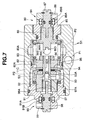
base valve device 50 comprises apartition wall member 55 and avalve housing 56 fluidically tightly mounted in the first path P1 formed in thesub tank 11C. Thepartition wall member 55 and thevalve housing 56 are fixed by aplug bolt 57 to be attached on thesub tank 11C. Thepartition wall member 55 separates the piston side chamber S2 from the reservoir chamber S3. Achannel 55A is formed in thepartition wall member 55. Abypass forming bolt 58 is fixed by anut 59 in the central part of thepartition wall member 55, with apressure side valve 60 for opening thechannel 55A at the time of compression, and a stretch side valve (check valve) 61 for communication throughchannel 55A at the time of stretch provided around the central part of thebypass forming bolt 58. Thepressure side valve 60 comprises a large number of plate like valve pieces laminated, is clamped and supported between thepartition wall member 55 and thebypass forming bolt 58 via avalve stopper 60A. Thestretch side valve 61 is biased by avalve spring 61A supported by its rear surface by thepartition wall member 55 so as to be seated on avalve receipt 62 clamped by thepartition wall member 55 and thevalve housing 56. Thepressure side valve 60 is seated on the flat surface of thestretch side valve 61 seated on thevalve receipt 62. - The
base valve device 50 comprises a second pressure side dampingforce adjusting device 70. - The second pressure side damping
force adjusting device 70 has abypass path 71 for communication between the piston side chamber S2 and the reservoir chamber S3 provided in thebypass forming bolt 58. Thebypass path 71 is provided parallel with thepressure side valve 60 and the stretch side valve 61 (channel 55A). The second pressure side dampingforce adjusting device 70 has arod supporting member 72 pressed in and fixed to the center of theplug bolt 57 fitted fluidically tightly to the topend cup part 58A of thebypass forming bolt 58, and comprises a dampingforce adjusting rod 73 to be attached onto arod supporting member 72 for adjusting the channel area of thebypass path 71. The dampingforce adjusting rod 73 is moved reciprocally in therod supporting member 72 according to the outside rotation operation of anadjuster rod 74 provided through theplug bolt 57 so that the channel area of thebypass path 71 can be adjusted by the topend needle valve 73A. Thebypass path 71 allows communication with the first path P1 on the reservoir chamber S3 side via thechannel 58B provided in the topend cup part 58A of thebypass forming bolt 58. - The
adjuster rod 74 is rotatable within theplug bolt 57 by theknob 75 fixed on the outer side end of saidplug bolt 57 so that a topend projection piece 74A of theadjuster rod 74 fixed in rotation on the base end recess part of the dampingforce adjusting rod 73 rotates saidrod 73 in the same direction and moves the topend needle valve 73A longitudinally.Balls 76B forced by set springs 76A are mounted in theplug bolt 57 on its outer side end face for engaging successively with engaging recess parts provided at a plurality of positions in the circumference direction of theknob 75 inner side end face so that theadjuster rod 74 can be set at any rotation operation position. - Therefore, in the low speed range of the compression process of the
hydraulic shock absorber 10, the oil corresponding to the entrance volume of thepiston rod 12 into thedamper cylinder 11B flows from the piston side chamber S2 to the reservoir chamber S3 via thebypass path 71 comprising the second pressure side dampingforce adjusting device 70 so as to generate the pressure side damping force (to be adjusted by the adjuster rod 74) generated by the aperture resistance of theneedle valve 73A of the dampingforce adjusting rod 73. Moreover, in the medium and high speed range, the oil of the piston side chamber S2 deflects and deforms thepressure side valve 60 so as to push and open the same for flowing into the reservoir chamber S3, and the deflected and deformed part of thepressure side valve 60 is separated from the flat surface of thestretch side valve 61 so as to generate the pressure side damping force derived from the flow resistance of the generated gap. - In the stretch process of the
hydraulic shock absorber 10, the oil corresponding to the withdrawal volume of thepiston rod 12 from thedamper cylinder 11B flows from the reservoir chamber S3 to the piston side chamber S2 via thebypass path 71, and the oil of the reservoir chamber S3 opens thestretch side valve 61 so as to be supplied to the piston side chamber S2. - The
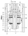
hydraulic shock absorber 10 comprises anouter side chamber 81 communicating with the piston rod side chamber S1 via theoil hole 27 formed in thedamper cylinder 11B, saidchamber 81 being defined between theouter cylinder 11A and thedamper cylinder 11B of thedamper case 11. Thehydraulic shock absorber 10 is provided with a second path P2 for communication between the reservoir chamber S3 and theouter side chamber 81 in theouter cylinder 11A of thedamper case 11. Theblow valve device 80 is provided in the second path P2 formed in thesub tank 11C. - As shown in FIG. 7, the
blow valve device 80 has avalve sheet 82 fluidically tightly mounted in the middle part of the second path P2 formed in thesub tank 11C, and thevalve sheet 82 is fixed by aplug bolt 91, or the like of the stretch side dampingforce adjusting device 90 to be described later. Thevalve sheet 82 separates the piston rod side chamber S1 and the reservoir chamber S3 communicating with each other via theouter side chamber 81. Achannel 82A is formed in thevalve sheet 82, and a plate likeblow valve 83 for opening or closing thechannel 82A is biased and seated by thevalve spring 83A. Theblow valve 83 is opened at the time the differential pressure between the piston rod side chamber S1 and the reservoir chamber S3 reaches a predetermined value so as to allow the oil to flow from the reservoir chamber S3 to the piston rod side chamber S1. - In FIG. 4, the solid line arrow represents the oil flow in the compression process, and the broken line arrow represents the oil flow at the time the
blow valve 83 is opened. - The
blow valve device 80 comprises a blowvalve adjusting device 84. - The blow
valve adjusting device 84 has a springforce adjusting rod 86 attached on theplug bolt 85 screwed on one end side of thesub tank 11C, and supports the rear surface of thevalve spring 83A by thewasher 86B supported by theflange 86A of the springforce adjusting rod 86. The springforce adjusting rod 86 is moved reciprocally according to the rotation operation from outside of anadjuster rod 87 provided through theplug bolt 85, so as to adjust the spring force of thevalve spring 83A, and thus to adjust the valve opening pressure of theblow valve 83. - The
adjuster rod 87 is secured to aknob 88 fixed on the outer side end, and engagingballs 89B forced by setsprings 89A stored in the outer side end face of theplug bolt 85 successively with engaging recess parts provided in a plurality of positions on the circumference of the inner side end face of theknob 88 so as to set theadjuster rod 87 at any rotation operation position. The topend stopper surface 86C of the springforce adjusting rod 86 is crashed against the end face of thebypass forming bolt 92 of the stretch side dampingforce adjusting device 90 to be described later at the time of the maximum compression of thevalve spring 83A by theadjuster rod 87, and it comprises aslot 86D for preventing closure of thebypass path 92A. - The blow'
valve device 80 comprises a stretch side dampingforce adjusting device 90. - The stretch side damping
force adjusting device 90 has aplug bolt 91 attached on the other end side (side opposite to the plug bolt 85) of thesub tank 11C. Thebypass forming bolt 92 attached on the center part of theplug bolt 91, is mounted inside asub valve sheet 93. A stretchside sub valve 94, avalve stopper 95, and the above-mentionedvalve sheet 82 in thebypass forming bolt 92, are secured by anut 96. Thebypass forming bolt 92 is provided with abypass path 92A opened on the piston rod side chamber S1 side, and thesub valve sheet 93 is provided with achannel 93A to be connected in series with thebypass path 92A and opened on the reservoir chamber S3 side. Thebypass path 92A and thechannel 93A are provided parallel with the blow valve 83 (channel 82A of the valve sheet 82). - The stretch side damping
force adjusting device 90 has a dampingforce adjusting rod 97 for adjusting the channel area of thebypass path 92A in thebypass forming bolt 92. The dampingforce adjusting rod 97 is moved reciprocally in thebypass forming bolt 92 according to the outer side rotation operation of anadjuster rod 98 provided through theplug bolt 91. The channel area of thebypass path 92A is adjusted by the topend needle valve 97A. Here, the stretchside sub valve 94 is backed up by thevalve stopper 95 via a plurality of shims, covers thechannel 93A from the reservoir chamber S3 side, and opens at the time the pressure of the piston rod side chamber S1 reaches or exceeds a certain value. - The
adjuster rod 98 is rotated within theplug bolt 91 by aknob 99 fixed on the outer side end of saidplug bolt 91 so that a topend projection piece 98A of theadjuster rod 98 is fixed in rotation on the base end recess part of the dampingforce adjusting rod 97 and rotates saidrod 97 in the same direction, thus moving the topend needle valve 97A longitudinally. By engagingballs 91B forced by setsprings 91A mounted in the outer side end face of theplug bolt 91 successively with engaging recess parts provided in a plurality of positions in the circumference direction of the inner side end face of theknob 99 it is possible to set theadjuster rod 98 at any rotation operation position. - Therefore, in the compression process of the
hydraulic shock absorber 10, at the time the differential pressure between the reservoir chamber S3 and the piston rod side chamber S1 reaches a predetermined value, theblow valve 83 is opened so as to avoid a negative pressure in the piston rod side chamber S1. The valve opening pressure of theblow valve 83 can be adjusted by the blowvalve adjusting device 84. - In the stretch process of the
hydraulic shock absorber 10, the oil of the piston side chamber S1 passes through thebypass path 92A comprising the stretch side dampingforce adjusting device 90, deflects and deforms the stretchside sub valve 94 so as to push and opens the same, and flows into the reservoir chamber S3. The stretch side damping force (to be adjusted by the adjuster rod 98) is generated by the aperture resistance of theneedle valve 97A of the dampingforce adjusting rod 97, and the stretch side damping force is derived from the flow resistance of the gap formed between the deflected and deformed part of the stretchside sub valve 94 and thesub valve sheet 93. The stretch side dampingforce adjusting device 90 can be omitted. - The
hydraulic shock absorber 10 executes the damping operation as follows. - In the low speed range of the compression process of the
hydraulic shock absorber 10, - (a) the pressure side damping force is generated by the oil
passing through the
bypass path 41 having the opening degree adjustment defined by the dampingforce adjusting rod 42 of the first pressure side dampingforce adjusting device 40, and the pressureside sub valve 32 provided in thesub piston channel 31A in thepiston valve device 30, and - (b) the pressure side damping force is generated by the oil
corresponding to the entrance volume of the piston rod passing through
the
bypass path 71 having the opening degree adjustment defined by the dampingforce adjusting rod 73 of the second pressure side dampingforce adjusting device 70 in thebase valve device 50. In the medium and high speed range, - (c) the pressure side damping force is generated by the oil
passing through the
pressure side valve 34 provided in thepressure side channel 35A of themain piston 35 in thepiston valve device 30, and - (d) the pressure side damping force is generated by the oil
corresponding to the entrance volume of the piston rod passing through
the
pressure side valve 60 provided in thechannel 55A of thepartition member 55 in thebase valve device 50. -
- Moreover, in the compression process (FIG. 1(A), 4 to 7) of the
hydraulic shock absorber 10, in all ranges from the low speed range to the medium and high speed range, theblow vale 83 is opened at the time the differential pressure between the piston rod side chamber S1 and the reservoir chamber S3 reaches a predetermined value, and the oil of the reservoir chamber S3 flows to the piston rod side chamber S1 so as to avoid a negative pressure in the piston rod side chamber S1. - In the low speed range in the stretch process of the
hydraulic shock absorber 10, - (a) the stretch side damping force is generated by the oil
passing through the
bypass path 92A having the opening degree adjustment defined by the dampingforce adjusting rod 97 of the stretch side dampingforce adjusting device 90 and the stretchside sub valve 94 provided in thechannel 93A of thesub valve sheet 93 in theblow valve device 80. In the medium and high speed range, - (b) the stretch side damping force is generated by the oil
passing through the
stretch side valve 36 provided in thestretch side channel 35B of themain piston 35 in thepiston valve device 30. -
- In the stretch process of the hydraulic shock absorber 10 (FIGS. 1(B), 5, 7), although the oil of the reservoir chamber S3 flows to the piston side chamber S2 through the stretch side valve (check valve) 61 of the
base valve device 50, the damping force is not generated in thestretch side valve 61. - According to the above-mentioned pressure side and stretch side damping forces, the stretching and contraction oscillation of the
hydraulic shock absorber 10 can be controlled. - According to this embodiment, the following effects can be achieved.
- (1) According to the setting of the
pressure side valves piston 35 and thepartition member 55 set for obtaining the desired pressure side damping force characteristics, in the case the piston rod side chamber S1 has a negative pressure, for example, if the damping force generated by thepressure side valve 34 of thepiston 35 is higher than the damping force generated by thepressure side vale 60 of thepartition wall member 55. In this case, at the time the differential pressure between the reservoir chamber S3 and the piston rod side chamber S1 reaches a predetermined value, theblow valve 83 provided in the path P2, 81 for communication between the reservoir chamber S3 and the piston rod side chamber S1 is opened so as to avoid a negative pressure in the piston rod side chamber S1. Then, since the valve opening pressure of theblow valve 83 can be adjusted from the outside, the negative pressure of the piston rod side chamber S1 can be avoided without changing thepressure side valves piston 35 and thepartition wall member 55. As a result, the troublesome replacement work accompanied by the change of thepressure side valves blow valve 83 is opened so that the reservoir chamber S3 and the piston rod side chamber S1 communicate with each other, the pressure of the piston rod side chamber S1 is increased. As a result, the rear pressure for forcing thepressure side valve 34 of themain piston 35 is increased so that the pressure side damping force generated by thepressure side valve 34 can be increased. - (2) By adjusting the valve opening pressure of the
blow vale 83, the pressure' of the piston rod side chamber S1 at the time of compression can be adjusted. As a result, the pressure side damping force generated by thepressure side valve 34 of themain piston 35 can be adjusted, and the damping force characteristics at the time of stretch can be adjusted. - (3) By providing the first pressure side damping
force adjusting device 40 to thepiston 35, and the second pressure side dampingforce adjusting device 70 to thepartition wall member 55, the adjusting width of the pressure side damping force can be made larger in the low speed range of the piston speed. - (4) Since the valve opening pressure of the
blow valve 83 can be adjusted from the outside, the negative pressure of the piston rod side chamber S1 can be avoided without changing the adjusting amounts of the first pressure side dampingforce adjusting device 40 and the second pressure side dampingforce adjusting device 70. As a result, the troublesome adjusting work for the first and second pressure side dampingforce adjusting devices - (5) Since the pressure of the piston rod side chamber S1 in the
low speed range at the time of compression can be adjusted by
adjusting the valve opening pressure of the
blow valve 83, the damping force characteristics in the low speed range at the time of stretch can be adjusted as well. - (6) Since the pressure
side sub valve 32 is provided on the downstream side of the first pressure side dampingforce adjusting device 40, the oil flow from the piston rod side chamber S1 to the piston side chamber S2 through the first pressure side dampingforce adjusting device 40 is inhibited by the pressureside sub valve 32 so that the first pressure side dampingforce adjusting device 40 can be provided as a damping force adjusting device dedicated to the pressure side. - (7) Moreover, in the case the reservoir chamber S3 and the
piston rod side chamber S1 communicate with each other, the pressure
of the piston rod side chamber S1 is increased. As a result, the rear
pressure for forcing the pressure
side sub valve 34 of themain piston 35 is increased so that the pressure side damping force in the low speed range generated in the pressureside sub valve 34 can be increased. Moreover, by adjusting the valve opening pressure of theblow valve 83, the pressure of the piston rod side chamber S1 at the time of compression can be adjusted. As a result, the pressure side damping force in the low speed range generated in the pressureside sub valve 34 of themain piston 35 can be adjusted. - (8) By providing only the pressure side damping
force adjusting device 40 to thepiston 35, the valve installation structure of thepiston 35 can be simplified. Moreover, since thebypass path 92A is provided to thevalve sheet 82 provided in the path for communication between the reservoir chamber S3 and the piston rod side chamber S1 and the stretch side dampingforce adjusting device 90 is provided to thebypass path 92A, the stretch side damping force in the low speed range can be adjusted independently. - (9) In the
hydraulic shock absorber 10 comprising thedamper case 11 with thesub tank 11C provided to theouter cylinder 11A, the above-mentioned items (1) to (8) can be realized in a simple pipe path configuration (layout). -
- As shown in FIG. 8, the
hydraulic shock absorber 100 according to a second embodiment comprises apiston 103 on the top end part of apiston rod 102 inserted fluidically tightly and slidably in a single cylindertype damper cylinder 101, and defining a piston rod side chamber S1 and a piston side chamber S2. Apartition wall member 104 is fluidically tightly mounted on the side opposite to the side with thepiston rod 102 inside thedamper cylinder 101. A reservoir chamber S3 is separated by apartition wall member 104 from the piston side chamber S2. A pressuringgas chamber 106 separated from the reservoir chamber S3 by adiaphragm 105 is provided inside thedamper cylinder 101. - Like the
hydraulic shock absorber 10 according to the first embodiment, thehydraulic shock absorber 100 comprises apiston valve device 110, abase valve device 120, and ablow valve device 130. - The
piston valve device 110 comprises, in thepiston 103, apressure side valve 111 for generating the damping force at the time of compression, and astretch side valve 112 for generating the damping force at the time of stretch. Thepiston valve device 110 is provided with abypass path 113 provided parallel with thepressure side valve 111 disposed in thepiston 103, and comprises a first pressuring side dampingforce adjusting device 114 for adjusting the aperture area of thebypass path 113. - The
base valve device 120 comprises, in thepartition wall member 104, apressure side valve 121 for generating the damping force at the time of compression, and a stretchside check valve 122 for allowing the flow at the time of stretch. Thebase valve device 120 is provided with abypass path 123 provided parallel with thepressure side valve 121 disposed in thepartition wall member 104, and comprises a second pressure side dampingforce adjusting device 124 for adjusting the aperture area of thebypass path 123. - The
blow valve device 130 is provided with avalve sheet 132 in apath 131 for communication between the reservoir chamber S3 and the piston rod side chamber S1, and comprises ablow valve 133 in thevalve sheet 132. Theblow valve 133 is opened at the time the differential pressure between the reservoir chamber S3 and the piston rod side chamber S1 reaches a predetermined value so as to allow the flow from the reservoir chamber S3 to the piston rod side chamber S1. Theblow valve 133 comprises a blowvalve adjusting device 134 additionally so that the blowvalve adjusting device 134 allows adjustment of the valve opening pressure of theblow valve 133 from outside. Theblow valve device 130 is provided with abypass path 135 provided parallel with theblow valve 133 in thevalve sheet 132, and comprises a stretch side dampingforce adjusting device 136 for adjusting the aperture area of thebypass path 135. The stretch side dampingforce adjusting device 136 comprises astretch side valve 137 to be opened at the time the pressure of the piston rod side chamber S1 reaches or exceeds a certain value in series with the stretch side dampingforce adjusting device 136. - According to this embodiment, the following effects can be achieved.
- (1) In the case the piston rod side chamber S1 has a negative
pressure according to the settings of the
pressure side valves piston 103 and thepartition wall member 104 set for obtaining a desired pressure side damping force characteristic, for example, in the case the damping force generated by thepressure side valve 111 of thepiston 103 is higher than the damping force generated by thepressure side valve 121 of thepartition wall member 104, in this case, at the time the differential pressure between the reservoir chamber S3 and the piston rod side chamber S1 reaches a predetermined value, theblow valve 133 provided in thepath 131 for communication between the reservoir chamber S3 and the piston rod side chamber S1 is opened so as to avoid a negative pressure in the piston rod side chamber S1. Then, since the valve opening pressure of theblow valve 133 can be adjusted from outside, the negative pressure of the piston rod side chamber S1 can be avoided without changing the settings of thepressure side valves piston 103 and thepartition wall member 104. As a result, the troublesome and time taking replacement work accompanied by the change of thepressure side valves - (2) By adjusting the valve opening pressure of the
blow valve 133, the pressure of the piston rod side chamber S1 at the time of compression can be adjusted as well, and the damping force at the time of compression can be adjusted, and the damping force characteristics at the time of stretch can be adjusted as well. - (3) By providing the first pressure side damping
force adjusting device 114 to thepiston 103 and providing the second pressure side dampingforce adjusting device 124 to thepartition wall member 104, the adjusting range of the pressure side damping force can be made larger in the low speed range of the piston speed. - (4) Since the valve opening pressure of the
blow valve 133 can be adjusted from outside, the negative pressure of the piston rod side chamber S1 can be avoided without changing the adjusting amounts of the first pressure side dampingforce adjusting device 114 and the second pressure side dampingforce adjusting device 124. As a result, the troublesome adjusting work of the first and second pressure side dampingforce adjusting devices - (5) Since the pressure of the piston rod side chamber S1 in the
low speed range at the time of compression can be adjusted as well by
adjusting the valve opening pressure of the
blow valve 133, the damping force characteristics in the low speed range at the time of stretch can be adjusted as well. - (6) By providing only the pressure side damping
force adjusting device 114 to thepiston 103, the valve installation structure of thepiston 103 can be simplified. Moreover, since thebypass path 135 is provided to thevalve sheet 132 provided in the path for communication between the reservoir chamber S3 and the piston rod side chamber S1, and the stretch side dampingforce adjusting device 136 to thebypass path 135, the stretch side damping force in the low speed range can be adjusted independently. -
- As heretofore explained, embodiments of the present invention have been described in detail with reference to the drawings. However, the specific configurations of the present invention are not limited to the embodiments but those having a modification of the design within the range of the present invention are also included in the present invention.
Claims (6)
- A hydraulic shock absorber comprising:characterised in that a path for communication (P2, 131) between the reservoir chamber and the piston rod side chamber is formed, a blow valve (80, 130) is provided in the path, to be opened at the time the differential pressure between the reservoir chamber (S3) and the piston rod side chamber (S1) reaches a predetermined value, for allowing oil to flow from the reservoir chamber (S3) to the piston rod side chamber (S1), and a blow valve adjusting device (84, 134) for operating the valve opening pressure of the blow valve (80, 130) from outside is provided.a piston provided in the top end part of a piston rod inserted slidably in a damper cylinder,a piston rod side chamber (S1) for storing the piston rod and a piston side chamber (S2) not storing the piston rod defined by the piston in the damper cylinder,a reservoir chamber (S3) separated from the piston side chamber (S2) not storing the piston rod by a partition wall member, andpressure side valves for generating the damping force at the time of compression provided each in the piston and the partition wall member,
- The hydraulic shock absorber according to claim 1, characterised in that a first bypass path (41, 113) parallel with the pressure side valve is provided in the piston, a first pressure side damping force adjusting device (40, 114) for adjusting the aperture area of the first bypass path is provided, a second bypass path (71, 123) parallel with the pressure side valve provided in the partition wall member is provided, and a second pressure side damping force adjusting device for adjusting the aperture area of the second bypass path is provided.
- The hydraulic shock absorber according to claim 1 or 2, characterised in that a pressure side sub valve is provided to the opening part to the piston rod side chamber of the first bypass path on the downstream side of the first pressure side damping force adjusting device.
- The hydraulic shock absorber according to any of claims 1 to 3, characterised in that a valve sheet is provided in the path for communication between the reservoir chamber and the piston rod side chamber, with the blow valve provided in the valve sheet and. a bypass path parallel with the blow valve, and a stretch side damping force adjusting device for adjusting the aperture area of the bypass path is provided.
- The hydraulic shock absorber according to any of claims 1 to 4, characterised in that it comprises a damper case comprising an outer cylinder and a sub tank provided integrally with the outer cylinder, the damper cylinder provided upright in the outer cylinder of the damper case,
an outside chamber communicating with the piston rod side chamber is defined between the outer cylinder and the damper cylinder, the reservoir chamber is provided in the sub tank,
a first path for communication between the piston side chamber and the reservoir chamber is provided in the outer cylinder and the sub tank, a second path for communication between the reservoir chamber and the outside chamber is provided,
the second pressure side damping force adjusting device is provided in the first path formed in the sub tank, and
a blow valve adjusting device for operating the valve opening pressure of the blow valve from the outside and the stretch side damping force adjusting device are provided in the second path formed in the sub tank. - The hydraulic shock absorber according to claim 2, characterised in that both the first pressure side damping force adjusting device and the second pressure side damping force adjusting device can adjust the aperture area of the bypass path from outside.
Applications Claiming Priority (2)
| Application Number | Priority Date | Filing Date | Title |
|---|---|---|---|
| JP2003288222 | 2003-08-06 | ||
| JP2003288222A JP4244171B2 (en) | 2003-08-06 | 2003-08-06 | Hydraulic buffer |
Publications (3)
| Publication Number | Publication Date |
|---|---|
| EP1505315A2 true EP1505315A2 (en) | 2005-02-09 |
| EP1505315A3 EP1505315A3 (en) | 2005-08-03 |
| EP1505315B1 EP1505315B1 (en) | 2006-12-20 |
Family
ID=33550036
Family Applications (1)
| Application Number | Title | Priority Date | Filing Date |
|---|---|---|---|
| EP20040007229 Expired - Fee Related EP1505315B1 (en) | 2003-08-06 | 2004-03-25 | Hydraulic shock absorber |
Country Status (3)
| Country | Link |
|---|---|
| EP (1) | EP1505315B1 (en) |
| JP (1) | JP4244171B2 (en) |
| DE (1) | DE602004003754T2 (en) |
Cited By (19)
| Publication number | Priority date | Publication date | Assignee | Title |
|---|---|---|---|---|
| WO2007046750A1 (en) * | 2005-10-19 | 2007-04-26 | öHLINS RACING AB | Arrangement for telescopic fork leg with parallel damping |
| DE102007009012B3 (en) * | 2007-02-23 | 2008-06-19 | Zf Friedrichshafen Ag | Piston/cylinder aggregate unit with dampening unit for hydraulic system |
| DE102007021854B3 (en) * | 2007-05-10 | 2008-08-28 | Stabilus Gmbh | Piston cylinder unit i.e. double tube damper, has ring chamber formed between piston rod-sided partition wall and piston rod-sided closure wall to stay in connection with piston rod-sided work space |
| US7607522B2 (en) | 2004-11-18 | 2009-10-27 | öHLINS RACING AB | Shock absorber for vehicles |
| EP2118515A1 (en) * | 2007-02-06 | 2009-11-18 | Öhlins Racing Ab | Shock absorber with hydraulic flow ducts |
| WO2010049524A1 (en) * | 2008-10-31 | 2010-05-06 | öHLINS RACING AB | Arrangement for telescopic fork leg with parallel damping |
| WO2016075156A1 (en) | 2014-11-10 | 2016-05-19 | öHLINS RACING AB | Removable insert system |
| EP3354928A1 (en) * | 2017-01-30 | 2018-08-01 | Fox Factory, Inc. | Twin tube shock with adjustable pressure regulation |
| CN108999912A (en) * | 2018-08-10 | 2018-12-14 | 上海曼杰汽车精密零部件有限公司 | shock absorber |
| US20190154100A1 (en) * | 2017-01-30 | 2019-05-23 | Fox Factory, Inc. | Twin tube shock with adjustable pressure regulation |
| EP3517801A1 (en) * | 2018-01-29 | 2019-07-31 | Fox Factory, Inc. | Twin tube shock with adjustable pressure regulation |
| US10704642B2 (en) * | 2018-01-24 | 2020-07-07 | Thyssenkrupp Bilstein Gmbh | Piston/damper tube assembly, vibration damper and method for operating a compression stage of a vibration damper |
| CN113969954A (en) * | 2020-07-23 | 2022-01-25 | 蒂森克虏伯比尔斯坦有限公司 | Shock absorber valve assembly with switchable bypass |
| CN114658786A (en) * | 2022-03-22 | 2022-06-24 | 常州纺织服装职业技术学院 | Large hydraulic damper for nuclear power station |
| CN114962524A (en) * | 2022-04-14 | 2022-08-30 | 苏世博(南京)减振系统有限公司 | Hydraulic damper and high-pressure sealing guide system for hydraulic damper |
| CN115654902A (en) * | 2022-11-15 | 2023-01-31 | 湖南嘉力亚新材料有限公司 | Green anode carbon bowl hole water blowing device |
| US20230242178A1 (en) * | 2020-06-02 | 2023-08-03 | Somic Management Holdings Inc. | Linear-motion damper and steering device |
| US11879517B2 (en) | 2019-03-04 | 2024-01-23 | Kyb Corporation | Shock absorber |
| WO2024020648A1 (en) * | 2022-07-28 | 2024-02-01 | The Dynamic Engineering Solution Pty Ltd | Hydraulic damper |
Families Citing this family (7)
| Publication number | Priority date | Publication date | Assignee | Title |
|---|---|---|---|---|
| CN101782127B (en) * | 2008-11-17 | 2013-03-27 | 株式会社万都 | Hydraulic stopper structure for a shock absorber |
| JP5426431B2 (en) | 2009-06-30 | 2014-02-26 | 株式会社ショーワ | Hydraulic shock absorber |
| JP2011012806A (en) * | 2010-02-25 | 2011-01-20 | Showa Corp | Hydraulic shock absorber |
| JP5466558B2 (en) * | 2010-03-29 | 2014-04-09 | カヤバ工業株式会社 | Adjuster device, shock absorber provided with adjuster device |
| DE102010029180A1 (en) | 2010-05-20 | 2011-11-24 | Suspa Gmbh | damper |
| JP5809311B2 (en) * | 2014-03-31 | 2015-11-10 | 株式会社ショーワ | Hydraulic shock absorber |
| JP2017067279A (en) * | 2015-10-02 | 2017-04-06 | 株式会社ショーワ | Buffer |
Citations (2)
| Publication number | Priority date | Publication date | Assignee | Title |
|---|---|---|---|---|
| JPH03292429A (en) * | 1990-04-06 | 1991-12-24 | Showa Mfg Co Ltd | Attenuation force generating mechanism of hydraulic shock absorber |
| JPH05248471A (en) * | 1992-03-06 | 1993-09-24 | Kayaba Ind Co Ltd | Hydraulic buffer |
-
2003
- 2003-08-06 JP JP2003288222A patent/JP4244171B2/en not_active Expired - Fee Related
-
2004
- 2004-03-25 EP EP20040007229 patent/EP1505315B1/en not_active Expired - Fee Related
- 2004-03-25 DE DE602004003754T patent/DE602004003754T2/en not_active Expired - Lifetime
Patent Citations (2)
| Publication number | Priority date | Publication date | Assignee | Title |
|---|---|---|---|---|
| JPH03292429A (en) * | 1990-04-06 | 1991-12-24 | Showa Mfg Co Ltd | Attenuation force generating mechanism of hydraulic shock absorber |
| JPH05248471A (en) * | 1992-03-06 | 1993-09-24 | Kayaba Ind Co Ltd | Hydraulic buffer |
Non-Patent Citations (2)
| Title |
|---|
| PATENT ABSTRACTS OF JAPAN vol. 016, no. 129 (M-1228), 2 April 1992 (1992-04-02) & JP 03 292429 A (SHOWA MFG CO LTD), 24 December 1991 (1991-12-24) * |
| PATENT ABSTRACTS OF JAPAN vol. 018, no. 006 (M-1537), 7 January 1994 (1994-01-07) -& JP 05 248471 A (KAYABA IND CO LTD), 24 September 1993 (1993-09-24) * |
Cited By (27)
| Publication number | Priority date | Publication date | Assignee | Title |
|---|---|---|---|---|
| US7607522B2 (en) | 2004-11-18 | 2009-10-27 | öHLINS RACING AB | Shock absorber for vehicles |
| WO2007046750A1 (en) * | 2005-10-19 | 2007-04-26 | öHLINS RACING AB | Arrangement for telescopic fork leg with parallel damping |
| EP1937995A1 (en) * | 2005-10-19 | 2008-07-02 | Öhlins Racing Ab | Arrangement for telescopic fork leg with parallel damping |
| EP1937995A4 (en) * | 2005-10-19 | 2010-02-24 | Oehlins Racing Ab | Arrangement for telescopic fork leg with parallel damping |
| US7766138B2 (en) | 2005-10-19 | 2010-08-03 | Ohlins Racing Ab | Arrangement for telescopic fork leg with parallel damping |
| EP2118515A1 (en) * | 2007-02-06 | 2009-11-18 | Öhlins Racing Ab | Shock absorber with hydraulic flow ducts |
| EP2118515A4 (en) * | 2007-02-06 | 2011-07-20 | Oehlins Racing Ab | Shock absorber with hydraulic flow ducts |
| US9091319B2 (en) | 2007-02-06 | 2015-07-28 | Ohlins Racing Ab | Shock absorber with hydraulic flow ducts |
| DE102007009012B3 (en) * | 2007-02-23 | 2008-06-19 | Zf Friedrichshafen Ag | Piston/cylinder aggregate unit with dampening unit for hydraulic system |
| DE102007021854B3 (en) * | 2007-05-10 | 2008-08-28 | Stabilus Gmbh | Piston cylinder unit i.e. double tube damper, has ring chamber formed between piston rod-sided partition wall and piston rod-sided closure wall to stay in connection with piston rod-sided work space |
| WO2010049524A1 (en) * | 2008-10-31 | 2010-05-06 | öHLINS RACING AB | Arrangement for telescopic fork leg with parallel damping |
| WO2016075156A1 (en) | 2014-11-10 | 2016-05-19 | öHLINS RACING AB | Removable insert system |
| EP3354928A1 (en) * | 2017-01-30 | 2018-08-01 | Fox Factory, Inc. | Twin tube shock with adjustable pressure regulation |
| US20180216692A1 (en) * | 2017-01-30 | 2018-08-02 | Fox Factory, Inc. | Twin tube shock with adjustable pressure regulation |
| US20190154100A1 (en) * | 2017-01-30 | 2019-05-23 | Fox Factory, Inc. | Twin tube shock with adjustable pressure regulation |
| EP3734107A1 (en) * | 2017-01-30 | 2020-11-04 | Fox Factory, Inc. | Twin tube shock with adjustable pressure regulation |
| US10704642B2 (en) * | 2018-01-24 | 2020-07-07 | Thyssenkrupp Bilstein Gmbh | Piston/damper tube assembly, vibration damper and method for operating a compression stage of a vibration damper |
| EP3919771A1 (en) * | 2018-01-29 | 2021-12-08 | Fox Factory, Inc. | Twin tube shock with adjustable pressure regulation |
| EP3517801A1 (en) * | 2018-01-29 | 2019-07-31 | Fox Factory, Inc. | Twin tube shock with adjustable pressure regulation |
| CN108999912A (en) * | 2018-08-10 | 2018-12-14 | 上海曼杰汽车精密零部件有限公司 | shock absorber |
| US11879517B2 (en) | 2019-03-04 | 2024-01-23 | Kyb Corporation | Shock absorber |
| US20230242178A1 (en) * | 2020-06-02 | 2023-08-03 | Somic Management Holdings Inc. | Linear-motion damper and steering device |
| CN113969954A (en) * | 2020-07-23 | 2022-01-25 | 蒂森克虏伯比尔斯坦有限公司 | Shock absorber valve assembly with switchable bypass |
| CN114658786A (en) * | 2022-03-22 | 2022-06-24 | 常州纺织服装职业技术学院 | Large hydraulic damper for nuclear power station |
| CN114962524A (en) * | 2022-04-14 | 2022-08-30 | 苏世博(南京)减振系统有限公司 | Hydraulic damper and high-pressure sealing guide system for hydraulic damper |
| WO2024020648A1 (en) * | 2022-07-28 | 2024-02-01 | The Dynamic Engineering Solution Pty Ltd | Hydraulic damper |
| CN115654902A (en) * | 2022-11-15 | 2023-01-31 | 湖南嘉力亚新材料有限公司 | Green anode carbon bowl hole water blowing device |
Also Published As
| Publication number | Publication date |
|---|---|
| EP1505315B1 (en) | 2006-12-20 |
| JP2005054942A (en) | 2005-03-03 |
| DE602004003754T2 (en) | 2007-10-11 |
| DE602004003754D1 (en) | 2007-02-01 |
| JP4244171B2 (en) | 2009-03-25 |
| EP1505315A3 (en) | 2005-08-03 |
Similar Documents
| Publication | Publication Date | Title |
|---|---|---|
| EP1505315B1 (en) | Hydraulic shock absorber | |
| US20090078517A1 (en) | Damping force adjusting structure of hydraulic shock absorber | |
| US6817454B2 (en) | Damping force control type hydraulic shock absorber | |
| US7322449B2 (en) | Hydraulic shock absorber | |
| US6997293B2 (en) | Front fork of motor cycle | |
| US8857582B2 (en) | Hydraulic shock absorber | |
| US8235187B2 (en) | Hydraulic shock absorber | |
| US4515253A (en) | Damping force generating device for an oil damper | |
| US20090084647A1 (en) | Damping force adjusting structure of hydraulic shock absorber | |
| US11655875B2 (en) | Damping valve and shock absorber | |
| EP3067584B1 (en) | Vehicle suspension system | |
| CN112105835A (en) | Pressure buffer device | |
| CN107614924B (en) | Shock absorber | |
| US20080053764A1 (en) | Front fork | |
| KR100585923B1 (en) | Hydraulic shock absorber with self leveling function for vehicle height | |
| US6182687B1 (en) | Pressure-dependent valve for a vibration damper | |
| US6374967B2 (en) | Damping force control type hydraulic shock absorber | |
| KR100507756B1 (en) | Apparatus for adjusting a damping force of a shock absorber using magnetoreological fluid | |
| JP2007263324A (en) | Hydraulic shock absorber | |
| US20100140884A1 (en) | Suspension and damping device for motor vehicles | |
| US11867253B2 (en) | Shock absorber | |
| US20060021833A1 (en) | Suspension and damping device for motor vehicles | |
| US11592074B2 (en) | Position-dependent shock absorber | |
| CN114233790A (en) | Shock absorber | |
| JP4341802B2 (en) | Hydraulic shock absorber and its spring load adjustment method |
Legal Events
| Date | Code | Title | Description |
|---|---|---|---|
| PUAI | Public reference made under article 153(3) epc to a published international application that has entered the european phase |
Free format text: ORIGINAL CODE: 0009012 |
|
| AK | Designated contracting states |
Kind code of ref document: A2 Designated state(s): AT BE BG CH CY CZ DE DK EE ES FI FR GB GR HU IE IT LI LU MC NL PL PT RO SE SI SK TR |
|
| AX | Request for extension of the european patent |
Extension state: AL LT LV MK |
|
| PUAL | Search report despatched |
Free format text: ORIGINAL CODE: 0009013 |
|
| AK | Designated contracting states |
Kind code of ref document: A3 Designated state(s): AT BE BG CH CY CZ DE DK EE ES FI FR GB GR HU IE IT LI LU MC NL PL PT RO SE SI SK TR |
|
| AX | Request for extension of the european patent |
Extension state: AL LT LV MK |
|
| RIC1 | Information provided on ipc code assigned before grant |
Ipc: 7F 16F 9/44 A Ipc: 7F 16F 9/46 B |
|
| GRAC | Information related to communication of intention to grant a patent modified |
Free format text: ORIGINAL CODE: EPIDOSCIGR1 |
|
| GRAP | Despatch of communication of intention to grant a patent |
Free format text: ORIGINAL CODE: EPIDOSNIGR1 |
|
| 17P | Request for examination filed |
Effective date: 20051110 |
|
| GRAS | Grant fee paid |
Free format text: ORIGINAL CODE: EPIDOSNIGR3 |
|
| AKX | Designation fees paid |
Designated state(s): DE GB IT |
|
| GRAA | (expected) grant |
Free format text: ORIGINAL CODE: 0009210 |
|
| AK | Designated contracting states |
Kind code of ref document: B1 Designated state(s): DE GB IT |
|
| REG | Reference to a national code |
Ref country code: GB Ref legal event code: FG4D |
|
| REF | Corresponds to: |
Ref document number: 602004003754 Country of ref document: DE Date of ref document: 20070201 Kind code of ref document: P |
|
| PLBE | No opposition filed within time limit |
Free format text: ORIGINAL CODE: 0009261 |
|
| STAA | Information on the status of an ep patent application or granted ep patent |
Free format text: STATUS: NO OPPOSITION FILED WITHIN TIME LIMIT |
|
| 26N | No opposition filed |
Effective date: 20070921 |
|
| PGFP | Annual fee paid to national office [announced via postgrant information from national office to epo] |
Ref country code: IT Payment date: 20100320 Year of fee payment: 7 |
|
| PGFP | Annual fee paid to national office [announced via postgrant information from national office to epo] |
Ref country code: GB Payment date: 20100322 Year of fee payment: 7 |
|
| PGFP | Annual fee paid to national office [announced via postgrant information from national office to epo] |
Ref country code: DE Payment date: 20100429 Year of fee payment: 7 |
|
| GBPC | Gb: european patent ceased through non-payment of renewal fee |
Effective date: 20110325 |
|
| PG25 | Lapsed in a contracting state [announced via postgrant information from national office to epo] |
Ref country code: DE Free format text: LAPSE BECAUSE OF NON-PAYMENT OF DUE FEES Effective date: 20111001 |
|
| REG | Reference to a national code |
Ref country code: DE Ref legal event code: R119 Ref document number: 602004003754 Country of ref document: DE Effective date: 20111001 |
|
| PG25 | Lapsed in a contracting state [announced via postgrant information from national office to epo] |
Ref country code: IT Free format text: LAPSE BECAUSE OF NON-PAYMENT OF DUE FEES Effective date: 20110325 Ref country code: GB Free format text: LAPSE BECAUSE OF NON-PAYMENT OF DUE FEES Effective date: 20110325 |