EP1505300A1 - Compressor - Google Patents
Compressor Download PDFInfo
- Publication number
- EP1505300A1 EP1505300A1 EP03719200A EP03719200A EP1505300A1 EP 1505300 A1 EP1505300 A1 EP 1505300A1 EP 03719200 A EP03719200 A EP 03719200A EP 03719200 A EP03719200 A EP 03719200A EP 1505300 A1 EP1505300 A1 EP 1505300A1
- Authority
- EP
- European Patent Office
- Prior art keywords
- refrigerant
- valve
- suction
- opening
- channel
- Prior art date
- Legal status (The legal status is an assumption and is not a legal conclusion. Google has not performed a legal analysis and makes no representation as to the accuracy of the status listed.)
- Granted
Links
Images



Classifications
-
- F—MECHANICAL ENGINEERING; LIGHTING; HEATING; WEAPONS; BLASTING
- F04—POSITIVE - DISPLACEMENT MACHINES FOR LIQUIDS; PUMPS FOR LIQUIDS OR ELASTIC FLUIDS
- F04B—POSITIVE-DISPLACEMENT MACHINES FOR LIQUIDS; PUMPS
- F04B39/00—Component parts, details, or accessories, of pumps or pumping systems specially adapted for elastic fluids, not otherwise provided for in, or of interest apart from, groups F04B25/00 - F04B37/00
- F04B39/0027—Pulsation and noise damping means
-
- F—MECHANICAL ENGINEERING; LIGHTING; HEATING; WEAPONS; BLASTING
- F04—POSITIVE - DISPLACEMENT MACHINES FOR LIQUIDS; PUMPS FOR LIQUIDS OR ELASTIC FLUIDS
- F04B—POSITIVE-DISPLACEMENT MACHINES FOR LIQUIDS; PUMPS
- F04B27/00—Multi-cylinder pumps specially adapted for elastic fluids and characterised by number or arrangement of cylinders
- F04B27/08—Multi-cylinder pumps specially adapted for elastic fluids and characterised by number or arrangement of cylinders having cylinders coaxial with, or parallel or inclined to, main shaft axis
- F04B27/10—Multi-cylinder pumps specially adapted for elastic fluids and characterised by number or arrangement of cylinders having cylinders coaxial with, or parallel or inclined to, main shaft axis having stationary cylinders
- F04B27/1036—Component parts, details, e.g. sealings, lubrication
-
- F—MECHANICAL ENGINEERING; LIGHTING; HEATING; WEAPONS; BLASTING
- F04—POSITIVE - DISPLACEMENT MACHINES FOR LIQUIDS; PUMPS FOR LIQUIDS OR ELASTIC FLUIDS
- F04B—POSITIVE-DISPLACEMENT MACHINES FOR LIQUIDS; PUMPS
- F04B49/00—Control, e.g. of pump delivery, or pump pressure of, or safety measures for, machines, pumps, or pumping installations, not otherwise provided for, or of interest apart from, groups F04B1/00 - F04B47/00
- F04B49/22—Control, e.g. of pump delivery, or pump pressure of, or safety measures for, machines, pumps, or pumping installations, not otherwise provided for, or of interest apart from, groups F04B1/00 - F04B47/00 by means of valves
- F04B49/225—Control, e.g. of pump delivery, or pump pressure of, or safety measures for, machines, pumps, or pumping installations, not otherwise provided for, or of interest apart from, groups F04B1/00 - F04B47/00 by means of valves with throttling valves or valves varying the pump inlet opening or the outlet opening
-
- F—MECHANICAL ENGINEERING; LIGHTING; HEATING; WEAPONS; BLASTING
- F04—POSITIVE - DISPLACEMENT MACHINES FOR LIQUIDS; PUMPS FOR LIQUIDS OR ELASTIC FLUIDS
- F04B—POSITIVE-DISPLACEMENT MACHINES FOR LIQUIDS; PUMPS
- F04B27/00—Multi-cylinder pumps specially adapted for elastic fluids and characterised by number or arrangement of cylinders
- F04B27/08—Multi-cylinder pumps specially adapted for elastic fluids and characterised by number or arrangement of cylinders having cylinders coaxial with, or parallel or inclined to, main shaft axis
- F04B27/14—Control
- F04B27/16—Control of pumps with stationary cylinders
- F04B27/18—Control of pumps with stationary cylinders by varying the relative positions of a swash plate and a cylinder block
- F04B27/1804—Controlled by crankcase pressure
- F04B2027/1863—Controlled by crankcase pressure with an auxiliary valve, controlled by
- F04B2027/1881—Suction pressure
-
- Y—GENERAL TAGGING OF NEW TECHNOLOGICAL DEVELOPMENTS; GENERAL TAGGING OF CROSS-SECTIONAL TECHNOLOGIES SPANNING OVER SEVERAL SECTIONS OF THE IPC; TECHNICAL SUBJECTS COVERED BY FORMER USPC CROSS-REFERENCE ART COLLECTIONS [XRACs] AND DIGESTS
- Y10—TECHNICAL SUBJECTS COVERED BY FORMER USPC
- Y10S—TECHNICAL SUBJECTS COVERED BY FORMER USPC CROSS-REFERENCE ART COLLECTIONS [XRACs] AND DIGESTS
- Y10S251/00—Valves and valve actuation
- Y10S251/902—Springs employed as valves
Definitions
- the present invention relates to a compressor that is used in, for example, a refrigeration circuit of an air conditioner for vehicles.
- a compressor of this type for example, as described in Japanese Patent Publication 2001-289177, there is known a compressor that includes a cylinder having a refrigerant inlet and a refrigerant outlet at one end, a piston reciprocating in the cylinder, and a tabular suction valve and a tabular discharge valve provided in the refrigerant inlet and the refrigerant outlet, such that the refrigerant inlet and the refrigerant outlet are opened and closed by elastic deformation of the suction valve and the discharge valve, respectively.
- a stopper that locks the one end side (free end side) of the suction valve in a predetermined opening position such that the suction valve opens and closes within a predetermined range.
- the suction valve may open and close in a range in which the suction valve does not come into abutment against the stopper.
- pulsation occurs in the suction refrigerant due to self-induced vibration of the suction valve, which causes vibration and noise in an evaporator and the like that are set in an external circuit on the refrigerant suction side.
- an opening regulating valve which regulates an opening of a channel according to a flow rate of a refrigerant, is provided in a refrigerant suction side channel of a cylinder head to reduce the opening of the opening regulating valve when a flow rate is low, whereby pulsation of the suction refrigerant propagating to the evaporator side is attenuated to reduce the vibration and noise of the evaporator and the like.
- the opening regulating valve has a complicated structure in which a valve body is housed in an exclusive valve case and biased in a predetermined direction by a spring attached in the valve case.
- a valve body is housed in an exclusive valve case and biased in a predetermined direction by a spring attached in the valve case.
- the present invention has been devised in view of the problems, and it is an object of the invention to provide a compressor that can reduce occurrence of vibration and noise due to self-induced vibration of an suction valve at the time of a low flow rate surely with an inexpensive structure.
- the present invention provides a compressor that includes a cylinder having a refrigerant inlet and a refrigerant outlet at one end, a cylinder head having a refrigerant suction chamber communicating with a refrigerant inlet and a refrigerant discharge chamber communicating with a refrigerant outlet, a piston reciprocating in the cylinder, and an suction valve provided in the refrigerant inlet, and a discharge valve provided in the refrigerant outlet, the refrigerant inlet and the refrigerant outlet being opened and closed by deformation of the suction valve and the discharge valve, respectively, characterized by including an opening regulating valve that is provided in a refrigerant channel communicating with the refrigerant suction chamber or the refrigerant discharge chamber, consists of an elastically deformable spiral member fixed in the channel at one end thereof, and regulates an opening of the channel by changing intervals among spiral portions of the spiral member according to a flow rate of the refrigerant.
- the intervals among the spiral portions of the opening regulating valve are widened when a flow rate is high, and the opening of the refrigerant channel increases.
- the pulsation of the refrigerant propagating to an external circuit on the refrigerant channel side is attenuated by the opening regulating valve.
- the invention forms the spiral member of the opening regulating valve such that diameters of the spiral portions gradually decrease from one side toward the other side thereof.
- the spiral member since the spiral member is formed such that the diameters of the spiral portions of the opening regulating valve gradually decrease from the one side toward the other side, the spiral member assumes a conical shape that is susceptible to a flow resistance of the refrigerant.
- the invention provides a blocking member, which blocks a part of the spiral member, in the opening regulating valve.
- Figures 1 to 3 show a first embodiment of the invention.
- This compressor includes a compressor body 10 that sucks and discharges a refrigerant, a piston 20 that is provided inside the compressor body 10, a drive unit 30 that drives the piston 20, and an opening regulating valve 40 that regulates an opening according to a flow rate of the refrigerant. Power from the outside is inputted to the drive unit 30.
- the compressor body 10 is formed in a cylindrical shape and includes a first housing 11 that is formed on the position of the piston 20 side, a second housing 12 that is formed on the position of the drive unit 30 side, a cylinder head 13 that is arranged on one end side of the first housing 11, and a valve plate 14 that is arranged between the first housing 11 and the cylinder head 13.
- the first housing 11 has a cylinder 11a that extends in an axial direction of the compressor body 10 and one end of the cylinder 11a opens to one end face of the first housing 11.
- a stopper 11b which locks an suction valve 14c to be described later in a predetermined opening position, is provided on one end side of the cylinder 11a, and the stopper 11b is formed by cutout of an edge of the cylinder 11a.
- the second housing 12 opens on one end side, and the inside thereof communicates with the cylinder 11a of the first housing 11.
- the cylinder head 13 is attached to one end of the first housing 11 via the valve plate 14, and a refrigerant discharge chamber 13a opening to the valve plate 14 side is provided in the center of the cylinder head 13.
- An annular refrigerant suction chamber 13b opening to the valve plate 14 side is provided around the refrigerant discharge chamber 13a, and the refrigerant suction chamber 13b communicates with a refrigerant suction channel 13c provided on a side of the cylinder head 13.
- the refrigerant discharge chamber 13a communicates with a refrigerant discharge channel (not shown) provided in the cylinder head 13.
- a refrigerant inlet 14a and a refrigerant outlet 14b communicating with the cylinder 11a are provided in the valve plate 14.
- the refrigerant inlet 14a communicates with the refrigerant suction chamber 13b of the cylinder head 13, and the refrigerant outlet 14b communicates with the refrigerant discharge chamber 13a.
- a tabular suction valve 14c and a tabular discharge valve 14d, which opens and closes the refrigerant inlet 14a and the refrigerant outlet 14b, respectively, are attached to the valve plate 14 such that the refrigerant inlet 14a and the refrigerant outlet 14b are opened and closed by elastic deformation of the suction valve 14c and the discharge valve 14d.
- One end side of the suction valve 14c is locked by the stopper 11b.
- the one end side of the suction valve 14c comes into pressed contact with the valve plate 14 side to close the refrigerant inlet 14a.
- the one end side of the suction valve 14c bends to the cylinder 11a side to open the refrigerant outlet 14b.
- the suction valve 14c has a maximum opening in a position where one end side (free end side) of the suction valve 14c is locked by the stopper 11b.
- a stopper plate 14e which locks the discharge valve 14d, is provided in the center of the valve plate 14. The discharge valve 14d is openable to a position where the discharge valve 14d is locked by the stopper plate 14e.
- the piston 20 is housed in the cylinder 11a so as to slide freely so as to suck and discharge a refrigerant to one end face side thereof.
- a semispherical shoe 21 which is coupled with the drive unit 30 side, is attached to the other side of the piston 20 so as to slide freely.
- the drive unit 30 includes a drive shaft 31 that is rotated by power from the outside, an inclining plate 32 that is rotated by the drive shaft 31, and an inclination regulating member 33 that regulates an inclination angle of the inclining plate 32 within a predetermined range.
- the drive shaft 31 is supported by the first housing 11 and the second housing 12 on one end side and the other end side so as to rotate freely via roller bearings 34, and for example, power of an engine of a vehicle is transmitted to the other end side via a not-shown pulley.
- the inclining plate 32 is supported by the drive shaft 31 via an annular slide member 32a so as to move freely in an axial direction and attached to the slide member 32a via a support shaft 32b.
- an inclination angle of the inclining plate 32 with respect to an axial direction of the drive shaft 31 changes arbitrarily around the support shaft 32b.
- a peripheral end of the inclining plate 32 is fitted in the shoe 21 of the piston 20 so as to slide freely such that the piston 20 reciprocates according to the inclination angle of the inclining plate 32 when the inclining plate 32 rotates.
- the inclination regulating member 33 is provided so as to rotate together with the drive shaft 31.
- a pin 33a provided at one end of the inclination regulating member 33 is inserted in a slit 32c provided in the inclining plate 32.
- the pin 33a moves in the slit 32c such that an inclination angle of the inclining plate 32 is regulated within a predetermined range according to a moving range of the pin 33a in the slit 32c.
- the opening regulating valve 40 is provided in the refrigerant suction channel 13c of the cylinder head 13 and includes an elastically deformable spiral member 41 fixed in the channel 13c at one end thereof.
- the spiral member 41 is formed such that diameters of spiral portions 41a gradually decrease from one end side to the other end side. Thus, when a flow rate of a refrigerant increases, intervals among the spiral portions 41a are widened by a flow resistance of the refrigerant.
- the inclination angle of the inclining plate 32 is changed according to a pressure applied to the other end side (housing 12 side) of the piston 20 due to a pressure difference, which is caused between the refrigerant suction chamber 13b and the second housing 12 by not-shown pressure control means, whereby a discharge amount of the piston 20 is controlled.
- the opening regulating valve 40 which is provided in the refrigerant suction channel 13c to the cylinder 11a, is formed by the elastically deformable spiral member 41, and the intervals among the spiral portions 41a of the spiral member 41 are changed according to a flow rate of a refrigerant, whereby an opening of the channel 13c is regulated.
- the spiral member 41 of the opening regulating valve 40 is formed such that the diameters of the spiral portions 41a gradually decrease from one end side to the other end side.
- the spiral member 41 assumes a conical shape that is susceptible a flow resistance of a refrigerant, and it is possible to perform opening and closing of the channel 13c surely.
- the opening regulating valve 40 is provided in the refrigerant suction channel 13c communicating with the refrigerant suction chamber 13b.
- the opening regulating valve 40 is provided in a refrigerant discharge side channel communicating with the refrigerant discharge chamber 13a.
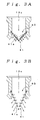
- FIGS. 4A and 4B show a second embodiment of the invention, and components equivalent to those in the above-described embodiment are denoted by the identical reference numerals and signs.
- an opening regulating valve 50 shown in the figures has a spiral member 51, which is the same as that in the above-described embodiment, and is formed such that diameters of spiral portions 51a thereof gradually decrease from one end side toward the other end side.
- a blocking member 52 which blocks a part of the other end side of the spiral member 51, is attached to the other end side of the opening regulating valve 50.
- This blocking member 52 is formed in, for example, a size for blocking intervals among the spiral portions 51a by about one round trip and is held by the topmost spiral portion 51a.
- the opening regulating valve 50 of this embodiment as in the first embodiment, intervals among the spiral portions 51a of the spiral member 51 change according to a flow rate of a refrigerant, an opening of the channel 13c is regulated, and the refrigerant does not pass a part where the blocking member 52 is attached.
- a flow rate of the refrigerant is regulated so much more for that.
- a flow rate in the refrigerant suction channel 13c can be made appropriate by the blocking member 52, it is possible to realize improvement of compression efficiency. In this case, it is possible to regulate an suction amount of the refrigerant arbitrarily by forming the blocking member 52 in an arbitrary size.
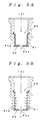
- FIGS. 5A and 5B show a third embodiment of the invention, and components equivalent to those in the above-described embodiments are denoted by the identical reference numerals and signs.
- an opening regulating valve 60 shown in the figures has an elastically deformable spiral member 61, and diameters of spiral portions 61a thereof are formed uniformly from one end side to the other end side.
- a blocking member 62 which blocks the other end side of the spiral member 61, is attached to the opening regulating valve 60.
- This blocking member 62 consists of a tabular member, and a hole 62a allowing a refrigerant to flow is provided in the center of the blocking member 62.
- the opening regulating valve 60 of this embodiment as in the first embodiment, intervals among the spiral portions 61a of the spiral member 61 change according to a flow rate of a refrigerant, an opening of the channel 13c is regulated, and the refrigerant does not pass a part where the blocking member 62 is attached.
- a flow rate of the refrigerant is regulated so much more for that.
- a spiral member of an opening regulating valve assumes a conical shape that is susceptible to a flow resistance f a refrigerant, it is possible to perform opening and closing of a refrigerant suction side channel surely.
Landscapes
- Engineering & Computer Science (AREA)
- Mechanical Engineering (AREA)
- General Engineering & Computer Science (AREA)
- Compressor (AREA)
- Compressors, Vaccum Pumps And Other Relevant Systems (AREA)
- Applications Or Details Of Rotary Compressors (AREA)
Abstract
Description
Claims (3)
- A compressor that includes a cylinder having a refrigerant inlet and a refrigerant outlet at one end, a cylinder head having a refrigerant suction chamber communicating with a refrigerant inlet and a refrigerant discharge chamber communicating with a refrigerant outlet, a piston reciprocating in the cylinder, and an suction valve provided in the refrigerant inlet, and a discharge valve provided in the refrigerant outlet, the refrigerant inlet and the refrigerant outlet being opened and closed by deformation of the suction valve and the discharge valve characterized by comprising an opening regulating valve that is provided in a refrigerant channel communicating with the refrigerant suction chamber or the refrigerant discharge chamber, consists of an elastically deformable spiral member fixed in the channel at one end thereof, and regulates an opening of the channel by changing intervals among spiral portions of the spiral member according to a flow rate of the refrigerant.
- The compressor according to claim 1, characterized in that the spiral member of the opening regulating valve is formed such that diameters of the spiral portions gradually decrease from one end side toward the other end side.
- The compressor according to claim 1 or 2, characterized in that a blocking member, which blocks a part of the spiral member, is provided in the opening regulating valve.
Applications Claiming Priority (3)
| Application Number | Priority Date | Filing Date | Title |
|---|---|---|---|
| JP2002136060 | 2002-05-10 | ||
| JP2002136060A JP2004027846A (en) | 2002-05-10 | 2002-05-10 | Compressor |
| PCT/JP2003/005346 WO2003095835A1 (en) | 2002-05-10 | 2003-04-25 | Compressor |
Publications (3)
| Publication Number | Publication Date |
|---|---|
| EP1505300A1 true EP1505300A1 (en) | 2005-02-09 |
| EP1505300A4 EP1505300A4 (en) | 2005-06-29 |
| EP1505300B1 EP1505300B1 (en) | 2006-11-22 |
Family
ID=29416770
Family Applications (1)
| Application Number | Title | Priority Date | Filing Date |
|---|---|---|---|
| EP03719200A Expired - Lifetime EP1505300B1 (en) | 2002-05-10 | 2003-04-25 | Compressor |
Country Status (7)
| Country | Link |
|---|---|
| US (1) | US7399169B2 (en) |
| EP (1) | EP1505300B1 (en) |
| JP (1) | JP2004027846A (en) |
| CN (1) | CN100366900C (en) |
| AU (1) | AU2003235137A1 (en) |
| DE (1) | DE60309858T2 (en) |
| WO (1) | WO2003095835A1 (en) |
Families Citing this family (8)
| Publication number | Priority date | Publication date | Assignee | Title |
|---|---|---|---|---|
| EP1751429B1 (en) * | 2004-05-17 | 2008-03-12 | Koninklijke Philips Electronics N.V. | Reciprocating pump with reduced noise level |
| JP4758728B2 (en) * | 2005-10-25 | 2011-08-31 | サンデン株式会社 | Reciprocating fluid machine |
| JP2007327446A (en) * | 2006-06-08 | 2007-12-20 | Valeo Thermal Systems Japan Corp | Opening adjusting valve and variable displacement compressor using this valve |
| JP4656044B2 (en) * | 2006-11-10 | 2011-03-23 | 株式会社豊田自動織機 | Compressor suction throttle valve |
| US8627805B2 (en) * | 2010-03-27 | 2014-01-14 | Cummins Inc. | System and apparatus for controlling reverse flow in a fluid conduit |
| JP6421747B2 (en) * | 2015-12-24 | 2018-11-14 | 株式会社豊田自動織機 | Compressor |
| KR102662655B1 (en) * | 2017-02-16 | 2024-05-03 | 삼성전자주식회사 | Compressor |
| KR102432063B1 (en) * | 2020-11-20 | 2022-08-12 | 한국항공우주연구원 | Flow control unit with compliant structure |
Family Cites Families (13)
| Publication number | Priority date | Publication date | Assignee | Title |
|---|---|---|---|---|
| US2125435A (en) * | 1935-11-05 | 1938-08-02 | Laval Separator Co De | Removing oil from flowing air streams |
| FR1329594A (en) * | 1961-11-08 | 1963-06-14 | Rech S Et Etudes Electroniques | Device introducing a variable and asymmetric pressure drop in a fluid flow |
| US3703913A (en) * | 1971-08-02 | 1972-11-28 | Cvc Co | Automatic rate of flow control valve |
| US3884447A (en) * | 1973-06-06 | 1975-05-20 | Wells Mfg Corp | Fluid valve means |
| US3896834A (en) * | 1973-10-09 | 1975-07-29 | Jr Herman L Paul | Valves with spring valve members |
| US4400142A (en) * | 1981-05-04 | 1983-08-23 | Carrier Corporation | Motor-compressor unit |
| JPS5891978A (en) * | 1981-11-24 | 1983-06-01 | Sadaji Umemoto | Valve using spiral elastic body |
| JPS5954788A (en) * | 1982-09-24 | 1984-03-29 | Matsushita Electric Ind Co Ltd | electric compressor |
| JP2546863B2 (en) | 1987-12-16 | 1996-10-23 | キヤノン株式会社 | Telephone |
| JPH01158856U (en) * | 1988-04-22 | 1989-11-02 | ||
| JPH0754658A (en) * | 1993-08-06 | 1995-02-28 | Yamato Seisakusho:Kk | Check valve for internal combustion engine |
| JP4181274B2 (en) * | 1998-08-24 | 2008-11-12 | サンデン株式会社 | Compressor |
| JP3933369B2 (en) * | 2000-04-04 | 2007-06-20 | サンデン株式会社 | Piston type variable capacity compressor |
-
2002
- 2002-05-10 JP JP2002136060A patent/JP2004027846A/en active Pending
-
2003
- 2003-04-25 AU AU2003235137A patent/AU2003235137A1/en not_active Abandoned
- 2003-04-25 DE DE60309858T patent/DE60309858T2/en not_active Expired - Lifetime
- 2003-04-25 US US10/513,765 patent/US7399169B2/en not_active Expired - Fee Related
- 2003-04-25 EP EP03719200A patent/EP1505300B1/en not_active Expired - Lifetime
- 2003-04-25 WO PCT/JP2003/005346 patent/WO2003095835A1/en not_active Ceased
- 2003-04-25 CN CNB03810623XA patent/CN100366900C/en not_active Expired - Lifetime
Also Published As
| Publication number | Publication date |
|---|---|
| US20050226749A1 (en) | 2005-10-13 |
| CN1653267A (en) | 2005-08-10 |
| DE60309858D1 (en) | 2007-01-04 |
| CN100366900C (en) | 2008-02-06 |
| EP1505300B1 (en) | 2006-11-22 |
| AU2003235137A1 (en) | 2003-11-11 |
| HK1081628A1 (en) | 2006-05-19 |
| EP1505300A4 (en) | 2005-06-29 |
| JP2004027846A (en) | 2004-01-29 |
| WO2003095835A1 (en) | 2003-11-20 |
| US7399169B2 (en) | 2008-07-15 |
| DE60309858T2 (en) | 2007-04-19 |
Similar Documents
| Publication | Publication Date | Title |
|---|---|---|
| CN101124405A (en) | capacity control valve | |
| EP1852607B1 (en) | Variable capacity swash plate type compressor | |
| US7399169B2 (en) | Compressor | |
| US7690898B2 (en) | Control valve for variable displacement compressor | |
| KR100461231B1 (en) | Suction muffler for compressor | |
| JP4429931B2 (en) | Opening adjustment valve | |
| CN101828034A (en) | Variable displacement compressor | |
| KR101099117B1 (en) | Check valve and compressor having the same | |
| KR20090083194A (en) | compressor | |
| HK1081628B (en) | Compressor | |
| KR102881675B1 (en) | Valve for back pressure control in scroll compressor | |
| EP1637737B1 (en) | Multi-cylinder reciprocating compressor | |
| JP2007327446A (en) | Opening adjusting valve and variable displacement compressor using this valve | |
| JP2002048059A (en) | Variable displacement cam plate type compressor | |
| KR102717002B1 (en) | Suction valve for variable capacity type compressor | |
| KR102130407B1 (en) | Compressor | |
| JP4118087B2 (en) | Compressor | |
| JP2003148337A (en) | Variable displacement compressor and air conditioner having compressor and control method for variable displacement compressor | |
| KR102524602B1 (en) | Suction valve for variable capacity type compressure | |
| JP2005083296A (en) | Compressor | |
| JP2009257149A (en) | Intake flow path changing adaptor | |
| KR20190012515A (en) | Compressor | |
| JP4498988B2 (en) | Opening adjustment valve | |
| KR200479804Y1 (en) | Check Valve Usable as a Suction or Discharge Valve | |
| WO2018003251A1 (en) | Control valve for variable-capacity compressor |
Legal Events
| Date | Code | Title | Description |
|---|---|---|---|
| PUAI | Public reference made under article 153(3) epc to a published international application that has entered the european phase |
Free format text: ORIGINAL CODE: 0009012 |
|
| 17P | Request for examination filed |
Effective date: 20041110 |
|
| AK | Designated contracting states |
Kind code of ref document: A1 Designated state(s): AT BE BG CH CY CZ DE DK EE ES FI FR GB GR HU IE IT LI LU MC NL PT RO SE SI SK TR |
|
| AX | Request for extension of the european patent |
Extension state: AL LT LV MK |
|
| A4 | Supplementary search report drawn up and despatched |
Effective date: 20050513 |
|
| RIC1 | Information provided on ipc code assigned before grant |
Ipc: 7F 04B 39/00 B Ipc: 7F 16K 1/40 B Ipc: 7F 04B 49/22 B Ipc: 7F 16K 15/14 B Ipc: 7F 04B 39/10 A Ipc: 7F 04B 27/10 B |
|
| DAX | Request for extension of the european patent (deleted) | ||
| RBV | Designated contracting states (corrected) |
Designated state(s): DE FR |
|
| GRAP | Despatch of communication of intention to grant a patent |
Free format text: ORIGINAL CODE: EPIDOSNIGR1 |
|
| GRAS | Grant fee paid |
Free format text: ORIGINAL CODE: EPIDOSNIGR3 |
|
| GRAA | (expected) grant |
Free format text: ORIGINAL CODE: 0009210 |
|
| AK | Designated contracting states |
Kind code of ref document: B1 Designated state(s): DE FR |
|
| REF | Corresponds to: |
Ref document number: 60309858 Country of ref document: DE Date of ref document: 20070104 Kind code of ref document: P |
|
| ET | Fr: translation filed | ||
| PLBE | No opposition filed within time limit |
Free format text: ORIGINAL CODE: 0009261 |
|
| STAA | Information on the status of an ep patent application or granted ep patent |
Free format text: STATUS: NO OPPOSITION FILED WITHIN TIME LIMIT |
|
| 26N | No opposition filed |
Effective date: 20070823 |
|
| PGFP | Annual fee paid to national office [announced via postgrant information from national office to epo] |
Ref country code: DE Payment date: 20130430 Year of fee payment: 11 |
|
| PGFP | Annual fee paid to national office [announced via postgrant information from national office to epo] |
Ref country code: FR Payment date: 20130417 Year of fee payment: 11 |
|
| REG | Reference to a national code |
Ref country code: DE Ref legal event code: R119 Ref document number: 60309858 Country of ref document: DE |
|
| REG | Reference to a national code |
Ref country code: DE Ref legal event code: R119 Ref document number: 60309858 Country of ref document: DE Effective date: 20141101 |
|
| REG | Reference to a national code |
Ref country code: FR Ref legal event code: ST Effective date: 20141231 |
|
| PG25 | Lapsed in a contracting state [announced via postgrant information from national office to epo] |
Ref country code: DE Free format text: LAPSE BECAUSE OF NON-PAYMENT OF DUE FEES Effective date: 20141101 |
|
| PG25 | Lapsed in a contracting state [announced via postgrant information from national office to epo] |
Ref country code: FR Free format text: LAPSE BECAUSE OF NON-PAYMENT OF DUE FEES Effective date: 20140430 |