EP1504841A1 - Retainer ring for wire package - Google Patents
Retainer ring for wire package Download PDFInfo
- Publication number
- EP1504841A1 EP1504841A1 EP04011757A EP04011757A EP1504841A1 EP 1504841 A1 EP1504841 A1 EP 1504841A1 EP 04011757 A EP04011757 A EP 04011757A EP 04011757 A EP04011757 A EP 04011757A EP 1504841 A1 EP1504841 A1 EP 1504841A1
- Authority
- EP
- European Patent Office
- Prior art keywords
- ring
- welding wire
- wire
- flexible
- stack
- Prior art date
- Legal status (The legal status is an assumption and is not a legal conclusion. Google has not performed a legal analysis and makes no representation as to the accuracy of the status listed.)
- Granted
Links
- 238000003466 welding Methods 0.000 claims abstract description 58
- 239000000463 material Substances 0.000 claims description 7
- 239000011230 binding agent Substances 0.000 claims description 5
- 229910000859 α-Fe Inorganic materials 0.000 claims description 5
- 239000002245 particle Substances 0.000 claims description 3
- 238000000034 method Methods 0.000 claims 4
- 229920000642 polymer Polymers 0.000 claims 1
- 230000036961 partial effect Effects 0.000 description 4
- 229910000831 Steel Inorganic materials 0.000 description 3
- 230000006872 improvement Effects 0.000 description 3
- 238000004519 manufacturing process Methods 0.000 description 3
- 229910052751 metal Inorganic materials 0.000 description 3
- 239000002184 metal Substances 0.000 description 3
- 239000010959 steel Substances 0.000 description 3
- 241000422980 Marietta Species 0.000 description 2
- 230000008901 benefit Effects 0.000 description 2
- 239000013065 commercial product Substances 0.000 description 2
- 238000013461 design Methods 0.000 description 2
- AJCDFVKYMIUXCR-UHFFFAOYSA-N oxobarium;oxo(oxoferriooxy)iron Chemical compound [Ba]=O.O=[Fe]O[Fe]=O.O=[Fe]O[Fe]=O.O=[Fe]O[Fe]=O.O=[Fe]O[Fe]=O.O=[Fe]O[Fe]=O.O=[Fe]O[Fe]=O AJCDFVKYMIUXCR-UHFFFAOYSA-N 0.000 description 2
- 230000000452 restraining effect Effects 0.000 description 2
- 238000012360 testing method Methods 0.000 description 2
- 239000004698 Polyethylene Substances 0.000 description 1
- 230000009471 action Effects 0.000 description 1
- 230000002411 adverse Effects 0.000 description 1
- 230000003247 decreasing effect Effects 0.000 description 1
- 230000001627 detrimental effect Effects 0.000 description 1
- 230000005672 electromagnetic field Effects 0.000 description 1
- 238000005516 engineering process Methods 0.000 description 1
- 239000000835 fiber Substances 0.000 description 1
- 238000010348 incorporation Methods 0.000 description 1
- 238000009434 installation Methods 0.000 description 1
- 239000006249 magnetic particle Substances 0.000 description 1
- 238000012986 modification Methods 0.000 description 1
- 230000004048 modification Effects 0.000 description 1
- 238000004806 packaging method and process Methods 0.000 description 1
- 230000035699 permeability Effects 0.000 description 1
- 239000004033 plastic Substances 0.000 description 1
- 229920003023 plastic Polymers 0.000 description 1
- -1 polyethylene Polymers 0.000 description 1
- 229920000573 polyethylene Polymers 0.000 description 1
- 230000002829 reductive effect Effects 0.000 description 1
- 238000012827 research and development Methods 0.000 description 1
- 238000004804 winding Methods 0.000 description 1
Images


Classifications
-
- B—PERFORMING OPERATIONS; TRANSPORTING
- B65—CONVEYING; PACKING; STORING; HANDLING THIN OR FILAMENTARY MATERIAL
- B65H—HANDLING THIN OR FILAMENTARY MATERIAL, e.g. SHEETS, WEBS, CABLES
- B65H59/00—Adjusting or controlling tension in filamentary material, e.g. for preventing snarling; Applications of tension indicators
- B65H59/02—Adjusting or controlling tension in filamentary material, e.g. for preventing snarling; Applications of tension indicators by regulating delivery of material from supply package
- B65H59/06—Adjusting or controlling tension in filamentary material, e.g. for preventing snarling; Applications of tension indicators by regulating delivery of material from supply package by devices acting on material leaving the package
-
- B—PERFORMING OPERATIONS; TRANSPORTING
- B23—MACHINE TOOLS; METAL-WORKING NOT OTHERWISE PROVIDED FOR
- B23K—SOLDERING OR UNSOLDERING; WELDING; CLADDING OR PLATING BY SOLDERING OR WELDING; CUTTING BY APPLYING HEAT LOCALLY, e.g. FLAME CUTTING; WORKING BY LASER BEAM
- B23K9/00—Arc welding or cutting
- B23K9/12—Automatic feeding or moving of electrodes or work for spot or seam welding or cutting
- B23K9/124—Circuits or methods for feeding welding wire
-
- B—PERFORMING OPERATIONS; TRANSPORTING
- B23—MACHINE TOOLS; METAL-WORKING NOT OTHERWISE PROVIDED FOR
- B23K—SOLDERING OR UNSOLDERING; WELDING; CLADDING OR PLATING BY SOLDERING OR WELDING; CUTTING BY APPLYING HEAT LOCALLY, e.g. FLAME CUTTING; WORKING BY LASER BEAM
- B23K9/00—Arc welding or cutting
- B23K9/12—Automatic feeding or moving of electrodes or work for spot or seam welding or cutting
- B23K9/133—Means for feeding electrodes, e.g. drums, rolls, motors
- B23K9/1333—Dereeling means
-
- B—PERFORMING OPERATIONS; TRANSPORTING
- B65—CONVEYING; PACKING; STORING; HANDLING THIN OR FILAMENTARY MATERIAL
- B65H—HANDLING THIN OR FILAMENTARY MATERIAL, e.g. SHEETS, WEBS, CABLES
- B65H49/00—Unwinding or paying-out filamentary material; Supporting, storing or transporting packages from which filamentary material is to be withdrawn or paid-out
- B65H49/02—Methods or apparatus in which packages do not rotate
- B65H49/04—Package-supporting devices
- B65H49/06—Package-supporting devices for a single operative package
- B65H49/08—Package-supporting devices for a single operative package enclosing the package
Definitions
- the present invention relates to a weld wire package and more particularly to an improved retainer ring for a loosely wound package, such as a fiber drum or cardboard box container or pail housing.
- Welding wire used in high production operations, such as robotic welding stations, is provided in a package having over 200 pounds of wire.
- the package is often a drum where a large volume of welding wire is looped in the drum around a central core or a central clearance bore. During transportation and use the volume of loop wire in the drum is decreased.
- To control the transportation and payout of the wire it is standard practice to provide an upper, weighted retainer ring.
- An early ring is shown in US 4,869,367 (Kawasaki) wherein the ring slides by its own weight along the inner surface of the drum by outwardly extending resilient members. These members center the ring over the top of the loop wire so the wire can be pulled to the center and paid out during welding.
- This patent is incorporated by reference herein as background technology which need not be repeated in this disclosure.
- a similar retainer ring is shown as prior art in US 5,277,314 (Cooper) directed to an improved upper retaining ring which has an inner contoured surface to facilitate wire payout without tangles.
- This patent is incorporated by reference herein.
- a retainer ring more close to the type of ring of the present invention is disclosed in US 5,819,934 wherein the ring is described as having a function during transportation to move downwardly as the welding wire settles in the drum. This patent is also incorporated by reference herein.
- the present invention relates to use of a particular material for the flat retainer ring.
- This material was introduced by Max Baermann in the late 1950's and is disclosed generally in US 3,051,988 (Baermann).
- the material according to this publication is barium ferrite in a non-magnetic, flexible binder and is commonly used for flexible magnet sheets of the type used for removable displays. Such material is now manufactured by many companies.
- the present invention utilizes a thin, flexible permanent magnet sheet manufactured by Flexmag, Inc. of Marietta, Ohio. A specification sheet for this commercially available material is also incorporated by reference herein with the Baermann patent.
- the present invention does not relate to any novelty in the flexible magnet sheet, which sheet is a standard commercial product having characteristics which need not be repeated in this disclosure.
- a common package is a drum where looped welding wire is deposited in the drum as a wire stack, or body, of wire having a top surface with an outer cylindrical surface against the drum and an inner cylindrical surface defining a central bore.
- the central bore is often occupied by a cardboard cylindrical core as shown in Cooper 5,819,934. It is common practice for the drum to have an upper retainer ring that is used in transportation to stabilize the body of welding wire as it settles.
- This ring is shown in Cooper 5,819,934 remains on the top of the welding wire to push downward by its weight so the wire can be pulled from the body of wire between the core and the ring.
- Each loop of wire has one turn of built-in twist so that when it is paid out, the twist introduced by releasing a loop of wire is canceled.
- the built-in twist causes the wire to spring up from the top of the stack when unrestrained.
- the weighted ring prevents wire from springing up due to the built-in twist.
- the weight of the ring is critical. Heavier rings tend to bend or recast the wire, causing wire to wobble when it exits the contact tip, although it is more effective to prevent tangle.
- Lighter rings can be easily lifted by the wire during payout, thus losing its contact to the top of the wire stack; and thereby losing its intended purpose of restraining wire movement at the top of the wire stack.
- Lighter rings have more propensity of tangle, although producing less wire wobble. This is the pitfall of the weighted ring design, essentially facing the difficulty of striking a balance of less tangle and less wire wobble. Tangles are detrimental to the operation of the package since they cause down time of the robotic welding station. Tangles are caused by many adverse movements of the wire loops on top of the wire stack.
- the wire has a winding cast that can snap around the outside of the retainer ring or the wire can bunch and slip at the inside of the retainer ring.
- the most common tangle is caused as wire is pulled from the inside of the ring and is referred to as "e script" because of its shape.
- An e script tangle stops operation of the welder and must be removed.
- Retainer rings so far on the market are not effective in preventing e script tangles.
- This type of tangle is caused by poor alignment of drive rolls of the wire feeder that builds up back-twist in the wire as it feeds the wire. The twist ultimately makes it way back to the drum and leads to an e script tangle.
- the objective of a retainer ring design is to increase operating welding time between successive e-tangles.
- the weighted retainer rings have not been successful in eliminating such tangles.
- the present invention is related to a retainer ring which essentially eliminates e script tangles in the welding wire being pulled from the center of the looped wire body of a drum package.
- the standard weighted retainer ring is formed from a thin flat, flexible permanent magnet sheet.
- the welding wire new package includes a cylindrical drum with a central axis and containing multiple layers of looped welding wire defining the wire stack to be paid out, which body has an upper ring shaped surface with an outer cylindrical surface generally matching the drum and an inner cylindrical surface defining a central bore concentric with the drum axis.
- the wire body is overlaid with a flexible permanent magnet ring on the top of the upper ring shaped surface. This magnet retainer ring allows welding wire to be paid out from under the ring and upwardly from the central bore of the welding wire body loaded into the drum.
- the flexible magnet sheet is a standard commercial product; however, its use as a retainer ring for a welding wire package involves cutting the commercial sheet into a ring shape having an outer periphery covering or overhanging the wire stack and an inner periphery which is generally circular and matches the inner surface of the stored welding wire stack.
- a standard weighted retainer ring such as shown in US 5,819,934, allowed such tangles at a rate of at least 25-30 times as frequent as a retainer ring constructed in accordance with the present invention.
- the ring when using a standard retainer ring, the ring is shifted over the top of the wire in an orbit motion determined by the circumferential location from which the wire is being pulled.
- the present invention does not allow movement of the ring over the top of the welding wire to thereby open space between the ring and the drum to cause tanglements.
- the primary object of the present invention is the provision of a retainer ring for a welding wire package which retainer ring is formed from a sheet of flexible permanent magnet material that is held on the top of the wire by the magnetic force created by the sheet and not by its weight.
- Still a further object of the present invention is the provision of a retainer ring, as defined above, which retainer ring requires no modification of the drum used in the welding wire package.
- Another object is to provide robust and intimate contact to the top of the wire stack from its flexible and magnetic nature, thus avoiding pitfalls of the rigid steel or plastic ring which can be lifted at one side by the force of the wire loses partial contact with the wire stack and decrease its effectiveness of restraining wire movement.
- Still a further object of the present invention is the provision of a retainer ring, as defined above, which retainer ring is fairly inexpensive, easy to manufacture and does not add weight or complexity to the welding wire package.
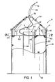
- FIGURES 1 and 2 A standard welding wire drum type package is shown in FIGURES 1 and 2 wherein wire W is stored in and paid out of cylindrical drum 10 having a bottom 12, a top 14 and an inside diameter 16.
- wire W is stored in and paid out of cylindrical drum 10 having a bottom 12, a top 14 and an inside diameter 16.
- a cylindrical cardboard core 20 having an outer diameter 22.
- Inside surface 16 and outside surface 22 are cylindrical and concentric with central axis a of drum 10.
- the top or lid of drum 10 (not shown) is removed and replaced with a feeding hat 30 including an upper grommet 32 communicated with a standard feed tube 34. Wire W is pulled from drum 10 during the welding operation.
- Package A is loaded at the wire manufacturing facility by being looped around core 20 to define a body of welding wire having a top surface 40, an outer cylindrical surface 42 against surface 16 and an inner cylindrical surface 44 against or close to surface 22.
- a central vertically extending bore 46 is concentric with axis a and around core 20.
- the core is not used, but center bore 46 is provided in the wire looping operation.
- the wire is looped in a manner that has a cast to facilitate payout with a minimum of tangles.
- a retainer ring is used in drum 10 to prevent tangles as wire W is pulled from the body of wire.
- the present invention is a retainer ring R cut from a flexible permanent magnet sheet having a top surface 60 and a bottom surface 62.
- the sheet is cut into a shape defining an outer periphery 64 and an inner periphery 66.
- ring R is spaced slightly inward of surface 16 and is not quite as small as the circumference of surface 22. Essentially, the ring R will fit within drum 10 and allow a gap between periphery 66 and surface 22 so wire W can be drawn from the top of the wire body and from under the retainer ring. This payout action is illustrated in FIGURE 3.
- the sheet from which ring R is formed is purchased from Flexmag Inc. in Marietta, Ohio.
- the thickness b of retainer ring is preferably 1/16 of an inch. The thickness can be adjusted generally between about 0.01-0.10 inches.
- the preferred sheet is made from ferrite particles in a non-magnetic binder.
- the ferrite is normally barium ferrite and the binder is polyethylene.
- the magnetic strength of the flexible sheet is preferably 0.6 Megagauss Oersteds. However, it has been found that a magnetic sheet having less than about 1.0 Megagauss Oersteds is used. Of course, other magnetic particles are used instead of the low cost ferrite, which is normally used in the commercial flexible permanent magnet sheets.
- the sheets can be easily machined by a punch press without losing any magnetic energy. As shown in FIGURE 3, the advantage of the present invention is that ring R is moved upwardly at the circumferential location where the wire is being pulled from the drum. This is illustrated as a flexed or lifted distance c.
- bottom surface 62 includes a plurality of opposite polarity magnetic poles 70, 74 spaced in various patterns. Indeed, the top surface could have the same magnetic poles so the orientation of ring R is not important. As wire W is pulled from the drum, ring R remains fixed in its position on the top of the wire due to the tremendous amount of magnetic forces in areas, other than where ring R is being flexed upwardly to allow withdrawal of the wire.
- ring R stays centered in the proper position during the payout operation and controls movement of the wire. It is understood that a rigid flexible permanent magnet ring would also stay generally centered and would be an improvement over the existing rigid steel weighted ring. The improvement would be use of magnetic force instead of the weight of the ring to maintain the position of the ring on the top of the wire. Furthermore, a magnet metal ring would remain generally in the right position during payout. Ring R does not shift vertically as a rigid unit on the top of the wire as the prior art shown generally in FIGURES 5 and 6.
- rigid metal ring 100 has a weight to hold it down against top surface 40 of the looped wire.
- Ring 100 has an outer periphery 102 and an inner periphery 104.
- This difficulty experienced in prior retainer rings is overcome by the present invention wherein a magnet ring is used.
- the magnet ring is flexible to allow deformation as shown in FIGURE 3, so it will adapt to uneven wire stack top surfaces.
- the present invention employs a magnetic field to restrain the welding wire of the stack.
- the field is preferably created by a ring formed from a thin permanent magnet, flexible sheet.
- the retainer ring is a thin magnetized steel ring.
- An electromagnetic field can be generated by an electromagnet mounted in hat 30. This field is directed by high permeability members to the top of the wire stack to control payout of the wire. This is a one time installation for use with successive wire packages.
Landscapes
- Engineering & Computer Science (AREA)
- Physics & Mathematics (AREA)
- Plasma & Fusion (AREA)
- Mechanical Engineering (AREA)
- Packaging Of Annular Or Rod-Shaped Articles, Wearing Apparel, Cassettes, Or The Like (AREA)
- Unwinding Of Filamentary Materials (AREA)
- Tension Adjustment In Filamentary Materials (AREA)
- Package Frames And Binding Bands (AREA)
Abstract
Description
Claims (20)
- A welding wire package (A) comprising a drum (10) or box with a central axis(a), multiple layers of looped welding wire defining a stack wire to be paid out, said stack having an upper ring shaped surface (40) with an outer cylindrical surface (42) and an inner cylindrical surface (44) defining a central bore (46) concentric with said central axis (a) and a flexible retainer ring (R) on top of said upper ring shaped surface, said retainer ring allowing welding wire to be paid from under the ring upwardly from said stack.
- A welding wire package as defined in claim 1, wherein said welding wire being paid from under the ring (R) upwardly from said central bore (46).
- A welding wire package as defined in claim 1 or 2, wherein said flexible ring (R) is polymer or rubber.
- A welding wire package as defined in any one of claims 1 to 3, wherein said flexible ring (R) is a permanent magnet.
- A welding wire package as defined in any one of claims 1 to 4, wherein said flexible ring (R) is a permanent magnet sheet.
- A welding wire package as defined in any one of claims 1 to 5, wherein said flexible ring (R) has a thickness in the general range of 0.10-0.01 inches.
- A welding wire package as defined in any one of claims 1 to 6, wherein said flexible magnet ring (R) has a magnetic strength of less than 1.0 Megagauss Oersteds.
- A welding wire package as defined in any one of claims 1 to 7, wherein said flexible ring (R) has an inner generally circular edge (66) with a diameter greater than the diameter of said inner cylindrical surface (44) of said wire stack.
- A welding wire package as defined in any one of claims 1 to 8, including a cylindrical core (20) in said bore (46) of said welding wire stack.
- A welding wire package as defined in any one of claims 1 to 9, wherein said flexible ring (R) has an outer periphery (64) generally matching said outer cylindrical surface (42) of said wire stack.
- A welding wire package as defined in claim 10, wherein said outer periphery (64) is generally circular.
- A welding wire package as defined in any one of claims 1 to 11, wherein said flexible ring (R) includes ferrite particles in a flexible non-magnetic binder.
- A retainer ring for use in a drum of looped welding wire said ring (R) being a flat sheet of permanent magnet material with an outer periphery (64) and an inner periphery (66).
- A retainer ring as defined in claim 13, wherein said ring (R) is flexible.
- A retainer ring as defined in claim 13 or 14, wherein said ring (R) has a thickness in the general range of 0.10-0.01 inches.
- A retainer ring as defined in any one of claims 13 to 15, wherein said ring (R) has a magnetic strength of less than 1.0 Megagauss Oersteds.
- A retainer ring as defined in any one of claims 13 to 16, wherein said ring (R) includes ferrite particles in a flexible non-magnetic binder.
- A method of controlling the payout of a welding wire (W) from a package at a welding operation, said package (A) comprising a stack of multiple layers of looped welding wire, said method including:(a) applying a magnetic field to the top of said stack; and,(b) pulling said wire from said stack for feeding to said welding operation.
- A method as defined in claim 18, wherein said applying act is by providing a flexible permanent magnet retainer ring (R) over the top of said stack.
- A method as defined in claim 18 or 19, wherein said applying act is accomplished by an electromagnet.
Applications Claiming Priority (2)
| Application Number | Priority Date | Filing Date | Title |
|---|---|---|---|
| US629044 | 2003-07-30 | ||
| US10/629,044 US7178755B2 (en) | 2003-07-30 | 2003-07-30 | Retainer ring for wire package |
Publications (2)
| Publication Number | Publication Date |
|---|---|
| EP1504841A1 true EP1504841A1 (en) | 2005-02-09 |
| EP1504841B1 EP1504841B1 (en) | 2009-03-25 |
Family
ID=33552865
Family Applications (1)
| Application Number | Title | Priority Date | Filing Date |
|---|---|---|---|
| EP04011757A Expired - Lifetime EP1504841B1 (en) | 2003-07-30 | 2004-05-18 | Retainer ring for wire package |
Country Status (10)
| Country | Link |
|---|---|
| US (1) | US7178755B2 (en) |
| EP (1) | EP1504841B1 (en) |
| JP (1) | JP4347755B2 (en) |
| KR (1) | KR100870165B1 (en) |
| AT (1) | ATE426478T1 (en) |
| AU (1) | AU2004201850B2 (en) |
| BR (1) | BRPI0401832A (en) |
| CA (1) | CA2465199A1 (en) |
| DE (1) | DE602004020152D1 (en) |
| MX (1) | MXPA04006209A (en) |
Cited By (2)
| Publication number | Priority date | Publication date | Assignee | Title |
|---|---|---|---|---|
| EP2035312A2 (en) * | 2006-06-16 | 2009-03-18 | Lincoln Global, Inc. | Guide ring for coiled wire |
| EP2810906A1 (en) * | 2013-06-06 | 2014-12-10 | SIDERGAS SpA | Retainer for a welding wire container and welding wire container |
Families Citing this family (38)
| Publication number | Priority date | Publication date | Assignee | Title |
|---|---|---|---|---|
| USRE40351E1 (en) * | 1996-07-24 | 2008-06-03 | Lincoln Global, Inc. | Mechanism for braking the unwinding of a bundle of metallic wire housed in a drum |
| US20030199464A1 (en) * | 2002-04-23 | 2003-10-23 | Silviu Itescu | Regeneration of endogenous myocardial tissue by induction of neovascularization |
| US7367452B1 (en) * | 2004-06-22 | 2008-05-06 | Lincoln Global, Inc. | Retainer ring for a wire package and method of using the same |
| US20070051716A1 (en) * | 2005-09-06 | 2007-03-08 | Lincoln Global, Inc. | Process for manufacturing packaged cored welding electrode |
| DE102006022841A1 (en) * | 2006-03-30 | 2007-10-04 | Sidergas Spa | Holder for a welding wire coil comprises fingers and a base element with an upper side and a lower side |
| KR100740253B1 (en) * | 2006-12-13 | 2007-07-16 | 고려용접봉 주식회사 | Pail-pack for welding wire |
| GB0711992D0 (en) * | 2007-06-21 | 2007-08-01 | Reckitt Benckiser Inc | Alkaline hard surface cleaning composition |
| KR100853530B1 (en) | 2007-07-06 | 2008-08-21 | 고려용접봉 주식회사 | Pail pack for welding wire |
| KR100853529B1 (en) * | 2007-07-06 | 2008-08-21 | 고려용접봉 주식회사 | Pail pack for welding wire |
| US7690593B2 (en) * | 2007-07-09 | 2010-04-06 | Lincoln Global, Inc. | Welding wire guide ring |
| US7721985B2 (en) * | 2007-07-09 | 2010-05-25 | Lincoln Global, Inc. | Welding wire guide ring |
| US7905439B2 (en) * | 2007-08-30 | 2011-03-15 | Lincoln Global, Inc. | Apparatus and method for tapered core drum package payoff |
| US7866586B2 (en) * | 2007-08-30 | 2011-01-11 | Lincoln Global, Inc. | Wire guide insert and method for drum package payoff |
| FI120164B2 (en) * | 2008-02-15 | 2012-07-13 | Mine On Line Service Oy | Method and apparatus for enhancing ore prospecting |
| US8453960B2 (en) | 2008-05-27 | 2013-06-04 | Awds Technologies Srl | Wire guiding system |
| KR101014669B1 (en) * | 2008-09-26 | 2011-02-16 | 송미희 | Welding apparatus in pursuit of stabile condition |
| ES2391485T3 (en) * | 2008-10-07 | 2012-11-27 | Sidergas Spa | Cap for welding wire container |
| US7938352B2 (en) | 2009-03-10 | 2011-05-10 | Lincoln Global, Inc. | Wire dispensing apparatus for packaged wire |
| EP2456590B1 (en) | 2009-07-20 | 2015-09-09 | AWDS Technologies SRL | A wire guiding liner, an particular a welding wire liner, with biasing means between articulated guiding bodies |
| US8235211B2 (en) * | 2009-08-21 | 2012-08-07 | Sidergas Spa | Retainer for welding wire container, having fingers and half-moon shaped holding tabs |
| US8393467B2 (en) * | 2009-08-21 | 2013-03-12 | Sidergas Spa | Retainer for welding wire container, having fingers and half-moon shaped holding tabs |
| US8127923B2 (en) * | 2009-11-13 | 2012-03-06 | Sidergas Spa | Container for welding wire |
| US8235341B2 (en) * | 2010-01-15 | 2012-08-07 | Parts Express International, Inc. | Wall mounting device |
| US8389901B1 (en) | 2010-05-27 | 2013-03-05 | Awds Technologies Srl | Welding wire guiding liner |
| US8985495B2 (en) * | 2010-07-09 | 2015-03-24 | Hyundai Welding Co., Ltd. | Device for preventing entanglement of welding wire |
| WO2012111213A1 (en) * | 2011-02-14 | 2012-08-23 | 本田技研工業株式会社 | Method and apparatus for manufacturing metal ring |
| US8882018B2 (en) * | 2011-12-19 | 2014-11-11 | Sidergas Spa | Retainer for welding wire container and welding wire container with retainer |
| US20140061361A1 (en) * | 2012-09-04 | 2014-03-06 | William R. Marble | String dispenser for dispensing string wound on a hollow core |
| BR112015010830B1 (en) | 2012-11-12 | 2021-09-14 | Southwire Company, Llc | CABLE PACKAGE |
| JP6118093B2 (en) * | 2012-12-10 | 2017-04-19 | 川崎重工業株式会社 | Welding wire storage container |
| US9162846B2 (en) | 2013-04-15 | 2015-10-20 | Lincoln Global, Inc. | Slip lift core for drums |
| US10343231B2 (en) | 2014-05-28 | 2019-07-09 | Awds Technologies Srl | Wire feeding system |
| US10010962B1 (en) | 2014-09-09 | 2018-07-03 | Awds Technologies Srl | Module and system for controlling and recording welding data, and welding wire feeder |
| US10350696B2 (en) | 2015-04-06 | 2019-07-16 | Awds Technologies Srl | Wire feed system and method of controlling feed of welding wire |
| US9975728B2 (en) | 2015-09-10 | 2018-05-22 | Sidergas Spa | Wire container lid, wire container and wire feeding system |
| US9950857B1 (en) | 2016-10-17 | 2018-04-24 | Sidergas Spa | Welding wire container |
| US11278981B2 (en) | 2020-01-20 | 2022-03-22 | Awds Technologies Srl | Device for imparting a torsional force onto a wire |
| US11174121B2 (en) | 2020-01-20 | 2021-11-16 | Awds Technologies Srl | Device for imparting a torsional force onto a wire |
Citations (4)
| Publication number | Priority date | Publication date | Assignee | Title |
|---|---|---|---|---|
| FR2278617A1 (en) * | 1974-07-18 | 1976-02-13 | Conflandey Forges Trefileries | Dispenser for magnetic wire on a spool - has ring magnets to prevent wire falling from spool when not being drawn out |
| SU584925A2 (en) * | 1976-08-01 | 1977-12-25 | Уральский Ордена Трудового Красного Знамени Политехнический Институт Имени Кирова | Wire uncoiling device |
| JP2001302096A (en) * | 2000-04-20 | 2001-10-31 | Nippon Steel Weld Prod & Eng Co Ltd | Loading device for welding wire |
| US6547176B1 (en) * | 2002-06-04 | 2003-04-15 | Air Liquide Canada Inc. | Wire unwinding controller |
Family Cites Families (25)
| Publication number | Priority date | Publication date | Assignee | Title |
|---|---|---|---|---|
| US2864565A (en) * | 1955-03-07 | 1958-12-16 | Rea Magnet Wire Company Inc | Apparatus for dispensing wire |
| US3051988A (en) | 1957-02-09 | 1962-09-04 | Baermann Max | Material with permanent magnetic properties |
| US3053410A (en) * | 1961-03-31 | 1962-09-11 | Sunray Company | Sliver can and seal therefor |
| FR2418519A1 (en) * | 1978-02-24 | 1979-09-21 | Thomson Csf | CASSETTE FOR VIDEODISC, AND VIDEODISC SUITABLE FOR SUCH A CASSETTE |
| CA1169390A (en) | 1980-12-29 | 1984-06-19 | Eiichiro Kawasaki | Welding wire container |
| US4395043A (en) * | 1981-02-20 | 1983-07-26 | Keystone Bingo Products, Inc. | Game chip |
| JPH0229092Y2 (en) * | 1984-11-14 | 1990-08-03 | ||
| JPH0386643A (en) * | 1989-08-28 | 1991-04-11 | Daido Steel Co Ltd | Soft decoration plate and manufacture thereof |
| JPH03116999A (en) | 1989-09-29 | 1991-05-17 | Mitsubishi Electric Corp | Ferrite rubber |
| JPH03264169A (en) | 1990-03-13 | 1991-11-25 | Daido Steel Co Ltd | Welding wire container |
| JPH0627268Y2 (en) * | 1990-07-27 | 1994-07-27 | 日鐵溶接工業株式会社 | Welding wire restraint member |
| JPH04112169A (en) | 1990-08-29 | 1992-04-14 | Nippon Steel Weld Prod & Eng Co Ltd | Pressing member for welding wire |
| JPH04133973A (en) | 1990-09-21 | 1992-05-07 | Nippon Steel Weld Prod & Eng Co Ltd | Pail pack for housing welding wire |
| EP0519424B1 (en) | 1991-06-18 | 1995-09-06 | The Lincoln Electric Company | Retainer ring for welding wire container |
| JP3102584B2 (en) * | 1991-09-04 | 2000-10-23 | シーアイ化成株式会社 | Oil-resistant and flexible magnet composition |
| DE69327457T2 (en) * | 1992-04-14 | 2000-06-15 | Rjf Int Corp | MAGNETIZED MATERIAL WITH HIGHER TENSILE FORCE AND METHOD AND DEVICE FOR MULTIPOLAR MAGNETIZATION OF THIS MATERIAL |
| JPH0627268A (en) | 1992-07-07 | 1994-02-04 | Y N S:Kk | Method for controlling light of on-vehicle electronic equipment |
| JPH09323120A (en) | 1996-06-04 | 1997-12-16 | Daido Steel Co Ltd | Manufacture of wound body of twisted wire and device therefor |
| IT1286954B1 (it) * | 1996-07-24 | 1998-07-24 | C I F E S P A | Dispositivo per la frenatura dello svolgimento di filo metallico in matassa alloggiato in fusto |
| US5827170A (en) * | 1996-12-26 | 1998-10-27 | Gebran; Emile | Therapeutic magnetic vortex ornament and device |
| US5819934A (en) | 1997-10-27 | 1998-10-13 | The Lincoln Electric Company | Wire transport drum |
| DE19907542C2 (en) * | 1999-02-22 | 2003-07-31 | Vacuumschmelze Gmbh | Flat magnetic core |
| US6406419B1 (en) * | 1999-03-25 | 2002-06-18 | Salar Farahmand | Eyeglass combination with permanent magnets |
| KR100350955B1 (en) | 2000-05-08 | 2002-08-30 | 고려용접봉 주식회사 | Pail pack for welding wire |
| US6745899B1 (en) * | 2002-02-25 | 2004-06-08 | Lincoln Global, Inc. | Wire payout |
-
2003
- 2003-07-30 US US10/629,044 patent/US7178755B2/en not_active Expired - Fee Related
-
2004
- 2004-04-26 CA CA002465199A patent/CA2465199A1/en not_active Abandoned
- 2004-05-03 AU AU2004201850A patent/AU2004201850B2/en not_active Ceased
- 2004-05-18 DE DE602004020152T patent/DE602004020152D1/en not_active Expired - Lifetime
- 2004-05-18 EP EP04011757A patent/EP1504841B1/en not_active Expired - Lifetime
- 2004-05-18 AT AT04011757T patent/ATE426478T1/en not_active IP Right Cessation
- 2004-05-25 BR BR0401832-0A patent/BRPI0401832A/en not_active IP Right Cessation
- 2004-06-18 JP JP2004180614A patent/JP4347755B2/en not_active Expired - Fee Related
- 2004-06-23 MX MXPA04006209A patent/MXPA04006209A/en active IP Right Grant
- 2004-07-19 KR KR1020040055947A patent/KR100870165B1/en not_active IP Right Cessation
Patent Citations (4)
| Publication number | Priority date | Publication date | Assignee | Title |
|---|---|---|---|---|
| FR2278617A1 (en) * | 1974-07-18 | 1976-02-13 | Conflandey Forges Trefileries | Dispenser for magnetic wire on a spool - has ring magnets to prevent wire falling from spool when not being drawn out |
| SU584925A2 (en) * | 1976-08-01 | 1977-12-25 | Уральский Ордена Трудового Красного Знамени Политехнический Институт Имени Кирова | Wire uncoiling device |
| JP2001302096A (en) * | 2000-04-20 | 2001-10-31 | Nippon Steel Weld Prod & Eng Co Ltd | Loading device for welding wire |
| US6547176B1 (en) * | 2002-06-04 | 2003-04-15 | Air Liquide Canada Inc. | Wire unwinding controller |
Non-Patent Citations (5)
| Title |
|---|
| PATENT ABSTRACTS OF JAPAN vol. 0160, no. 77 (M - 1214) 25 February 1992 (1992-02-25) * |
| PATENT ABSTRACTS OF JAPAN vol. 0163, no. 59 (M - 1289) 4 August 1992 (1992-08-04) * |
| PATENT ABSTRACTS OF JAPAN vol. 0163, no. 99 (M - 1300) 24 August 1992 (1992-08-24) * |
| PATENT ABSTRACTS OF JAPAN vol. 1998, no. 04 31 March 1998 (1998-03-31) * |
| PATENT ABSTRACTS OF JAPAN vol. 2002, no. 02 2 April 2002 (2002-04-02) * |
Cited By (3)
| Publication number | Priority date | Publication date | Assignee | Title |
|---|---|---|---|---|
| EP2035312A2 (en) * | 2006-06-16 | 2009-03-18 | Lincoln Global, Inc. | Guide ring for coiled wire |
| EP2035312A4 (en) * | 2006-06-16 | 2009-11-18 | Lincoln Global Inc | Guide ring for coiled wire |
| EP2810906A1 (en) * | 2013-06-06 | 2014-12-10 | SIDERGAS SpA | Retainer for a welding wire container and welding wire container |
Also Published As
| Publication number | Publication date |
|---|---|
| DE602004020152D1 (en) | 2009-05-07 |
| ATE426478T1 (en) | 2009-04-15 |
| KR100870165B1 (en) | 2008-11-25 |
| MXPA04006209A (en) | 2005-02-03 |
| KR20050014669A (en) | 2005-02-07 |
| AU2004201850B2 (en) | 2005-06-16 |
| BRPI0401832A (en) | 2005-05-24 |
| AU2004201850A1 (en) | 2005-02-17 |
| JP2005046910A (en) | 2005-02-24 |
| US7178755B2 (en) | 2007-02-20 |
| EP1504841B1 (en) | 2009-03-25 |
| US20050023392A1 (en) | 2005-02-03 |
| JP4347755B2 (en) | 2009-10-21 |
| CA2465199A1 (en) | 2005-01-30 |
Similar Documents
| Publication | Publication Date | Title |
|---|---|---|
| EP1504841B1 (en) | Retainer ring for wire package | |
| US7798326B2 (en) | Retainer ring for a wire package and method of using the same | |
| EP2035312B1 (en) | Guide ring for coiled wire | |
| EP2176025B1 (en) | Welding wire guide ring with sloped surface | |
| US7198152B2 (en) | Welding wire container with ribbed walls and mating retainer ring | |
| US7004318B2 (en) | Wire payout | |
| US6889835B2 (en) | Packaging for containing and dispensing large quantities of wire | |
| KR100638691B1 (en) | Welding wire payout drum and wire storage stem thereof | |
| JPH1080720A (en) | Braking device for unwinding wire bundle | |
| JP2001179450A (en) | Device for housing welding wire | |
| US20080110779A1 (en) | Wire payoff brush and container containing a wire payoff brush | |
| EP2354039A1 (en) | Container for welding wire with internal retainer | |
| US8985495B2 (en) | Device for preventing entanglement of welding wire | |
| JPH04133973A (en) | Pail pack for housing welding wire | |
| JP2011136346A (en) | Pressing member for pail pack, container for pail pack and welding-wire-storing pail pack | |
| EP3851402A1 (en) | Metal spool | |
| CA3081174A1 (en) | Container with anti-wire-entangling device for packaging and paying out coiled welding wire | |
| EP2353765A1 (en) | Container for welding wire with reinforcing strips in its peripheral wall | |
| JPS598474B2 (en) | How to pull out welding wire stored in a pail container | |
| US20090090801A1 (en) | Sidewall thread bobbin | |
| JPH11123456A (en) | Compact coil |
Legal Events
| Date | Code | Title | Description |
|---|---|---|---|
| PUAI | Public reference made under article 153(3) epc to a published international application that has entered the european phase |
Free format text: ORIGINAL CODE: 0009012 |
|
| AK | Designated contracting states |
Kind code of ref document: A1 Designated state(s): AT BE BG CH CY CZ DE DK EE ES FI FR GB GR HU IE IT LI LU MC NL PL PT RO SE SI SK TR |
|
| AX | Request for extension of the european patent |
Extension state: AL HR LT LV MK |
|
| 17P | Request for examination filed |
Effective date: 20050110 |
|
| REG | Reference to a national code |
Ref country code: HK Ref legal event code: DE Ref document number: 1073815 Country of ref document: HK |
|
| AKX | Designation fees paid |
Designated state(s): AT BE BG CH CY CZ DE DK EE ES FI FR GB GR HU IE IT LI LU MC NL PL PT RO SE SI SK TR |
|
| RAP1 | Party data changed (applicant data changed or rights of an application transferred) |
Owner name: LINCOLN GLOBAL, INC. |
|
| RAP1 | Party data changed (applicant data changed or rights of an application transferred) |
Owner name: LINCOLN GLOBAL, INC. |
|
| 17Q | First examination report despatched |
Effective date: 20070514 |
|
| GRAP | Despatch of communication of intention to grant a patent |
Free format text: ORIGINAL CODE: EPIDOSNIGR1 |
|
| GRAS | Grant fee paid |
Free format text: ORIGINAL CODE: EPIDOSNIGR3 |
|
| GRAA | (expected) grant |
Free format text: ORIGINAL CODE: 0009210 |
|
| AK | Designated contracting states |
Kind code of ref document: B1 Designated state(s): AT BE BG CH CY CZ DE DK EE ES FI FR GB GR HU IE IT LI LU MC NL PL PT RO SE SI SK TR |
|
| REG | Reference to a national code |
Ref country code: GB Ref legal event code: FG4D |
|
| REG | Reference to a national code |
Ref country code: CH Ref legal event code: EP |
|
| REG | Reference to a national code |
Ref country code: IE Ref legal event code: FG4D |
|
| REF | Corresponds to: |
Ref document number: 602004020152 Country of ref document: DE Date of ref document: 20090507 Kind code of ref document: P |
|
| PG25 | Lapsed in a contracting state [announced via postgrant information from national office to epo] |
Ref country code: SI Free format text: LAPSE BECAUSE OF FAILURE TO SUBMIT A TRANSLATION OF THE DESCRIPTION OR TO PAY THE FEE WITHIN THE PRESCRIBED TIME-LIMIT Effective date: 20090325 Ref country code: FI Free format text: LAPSE BECAUSE OF FAILURE TO SUBMIT A TRANSLATION OF THE DESCRIPTION OR TO PAY THE FEE WITHIN THE PRESCRIBED TIME-LIMIT Effective date: 20090325 |
|
| PG25 | Lapsed in a contracting state [announced via postgrant information from national office to epo] |
Ref country code: AT Free format text: LAPSE BECAUSE OF FAILURE TO SUBMIT A TRANSLATION OF THE DESCRIPTION OR TO PAY THE FEE WITHIN THE PRESCRIBED TIME-LIMIT Effective date: 20090325 Ref country code: PL Free format text: LAPSE BECAUSE OF FAILURE TO SUBMIT A TRANSLATION OF THE DESCRIPTION OR TO PAY THE FEE WITHIN THE PRESCRIBED TIME-LIMIT Effective date: 20090325 Ref country code: SE Free format text: LAPSE BECAUSE OF FAILURE TO SUBMIT A TRANSLATION OF THE DESCRIPTION OR TO PAY THE FEE WITHIN THE PRESCRIBED TIME-LIMIT Effective date: 20090625 |
|
| NLV1 | Nl: lapsed or annulled due to failure to fulfill the requirements of art. 29p and 29m of the patents act | ||
| PG25 | Lapsed in a contracting state [announced via postgrant information from national office to epo] |
Ref country code: BE Free format text: LAPSE BECAUSE OF FAILURE TO SUBMIT A TRANSLATION OF THE DESCRIPTION OR TO PAY THE FEE WITHIN THE PRESCRIBED TIME-LIMIT Effective date: 20090325 |
|
| PG25 | Lapsed in a contracting state [announced via postgrant information from national office to epo] |
Ref country code: PT Free format text: LAPSE BECAUSE OF FAILURE TO SUBMIT A TRANSLATION OF THE DESCRIPTION OR TO PAY THE FEE WITHIN THE PRESCRIBED TIME-LIMIT Effective date: 20090901 Ref country code: CZ Free format text: LAPSE BECAUSE OF FAILURE TO SUBMIT A TRANSLATION OF THE DESCRIPTION OR TO PAY THE FEE WITHIN THE PRESCRIBED TIME-LIMIT Effective date: 20090325 Ref country code: EE Free format text: LAPSE BECAUSE OF FAILURE TO SUBMIT A TRANSLATION OF THE DESCRIPTION OR TO PAY THE FEE WITHIN THE PRESCRIBED TIME-LIMIT Effective date: 20090325 Ref country code: ES Free format text: LAPSE BECAUSE OF FAILURE TO SUBMIT A TRANSLATION OF THE DESCRIPTION OR TO PAY THE FEE WITHIN THE PRESCRIBED TIME-LIMIT Effective date: 20090706 |
|
| PG25 | Lapsed in a contracting state [announced via postgrant information from national office to epo] |
Ref country code: SK Free format text: LAPSE BECAUSE OF FAILURE TO SUBMIT A TRANSLATION OF THE DESCRIPTION OR TO PAY THE FEE WITHIN THE PRESCRIBED TIME-LIMIT Effective date: 20090325 Ref country code: NL Free format text: LAPSE BECAUSE OF FAILURE TO SUBMIT A TRANSLATION OF THE DESCRIPTION OR TO PAY THE FEE WITHIN THE PRESCRIBED TIME-LIMIT Effective date: 20090325 Ref country code: RO Free format text: LAPSE BECAUSE OF FAILURE TO SUBMIT A TRANSLATION OF THE DESCRIPTION OR TO PAY THE FEE WITHIN THE PRESCRIBED TIME-LIMIT Effective date: 20090325 |
|
| PG25 | Lapsed in a contracting state [announced via postgrant information from national office to epo] |
Ref country code: MC Free format text: LAPSE BECAUSE OF NON-PAYMENT OF DUE FEES Effective date: 20090531 |
|
| REG | Reference to a national code |
Ref country code: CH Ref legal event code: PL |
|
| PG25 | Lapsed in a contracting state [announced via postgrant information from national office to epo] |
Ref country code: CH Free format text: LAPSE BECAUSE OF NON-PAYMENT OF DUE FEES Effective date: 20090531 Ref country code: LI Free format text: LAPSE BECAUSE OF NON-PAYMENT OF DUE FEES Effective date: 20090531 Ref country code: BG Free format text: LAPSE BECAUSE OF FAILURE TO SUBMIT A TRANSLATION OF THE DESCRIPTION OR TO PAY THE FEE WITHIN THE PRESCRIBED TIME-LIMIT Effective date: 20090625 Ref country code: DK Free format text: LAPSE BECAUSE OF FAILURE TO SUBMIT A TRANSLATION OF THE DESCRIPTION OR TO PAY THE FEE WITHIN THE PRESCRIBED TIME-LIMIT Effective date: 20090325 |
|
| PLBE | No opposition filed within time limit |
Free format text: ORIGINAL CODE: 0009261 |
|
| STAA | Information on the status of an ep patent application or granted ep patent |
Free format text: STATUS: NO OPPOSITION FILED WITHIN TIME LIMIT |
|
| GBPC | Gb: european patent ceased through non-payment of renewal fee |
Effective date: 20090625 |
|
| REG | Reference to a national code |
Ref country code: FR Ref legal event code: ST Effective date: 20100129 |
|
| 26N | No opposition filed |
Effective date: 20091229 |
|
| REG | Reference to a national code |
Ref country code: IE Ref legal event code: MM4A |
|
| PG25 | Lapsed in a contracting state [announced via postgrant information from national office to epo] |
Ref country code: FR Free format text: LAPSE BECAUSE OF NON-PAYMENT OF DUE FEES Effective date: 20090602 Ref country code: IE Free format text: LAPSE BECAUSE OF NON-PAYMENT OF DUE FEES Effective date: 20090518 |
|
| PG25 | Lapsed in a contracting state [announced via postgrant information from national office to epo] |
Ref country code: GB Free format text: LAPSE BECAUSE OF NON-PAYMENT OF DUE FEES Effective date: 20090625 |
|
| PG25 | Lapsed in a contracting state [announced via postgrant information from national office to epo] |
Ref country code: GR Free format text: LAPSE BECAUSE OF FAILURE TO SUBMIT A TRANSLATION OF THE DESCRIPTION OR TO PAY THE FEE WITHIN THE PRESCRIBED TIME-LIMIT Effective date: 20090626 |
|
| PG25 | Lapsed in a contracting state [announced via postgrant information from national office to epo] |
Ref country code: LU Free format text: LAPSE BECAUSE OF NON-PAYMENT OF DUE FEES Effective date: 20090518 |
|
| PG25 | Lapsed in a contracting state [announced via postgrant information from national office to epo] |
Ref country code: HU Free format text: LAPSE BECAUSE OF FAILURE TO SUBMIT A TRANSLATION OF THE DESCRIPTION OR TO PAY THE FEE WITHIN THE PRESCRIBED TIME-LIMIT Effective date: 20090926 |
|
| PG25 | Lapsed in a contracting state [announced via postgrant information from national office to epo] |
Ref country code: TR Free format text: LAPSE BECAUSE OF FAILURE TO SUBMIT A TRANSLATION OF THE DESCRIPTION OR TO PAY THE FEE WITHIN THE PRESCRIBED TIME-LIMIT Effective date: 20090325 |
|
| PG25 | Lapsed in a contracting state [announced via postgrant information from national office to epo] |
Ref country code: CY Free format text: LAPSE BECAUSE OF FAILURE TO SUBMIT A TRANSLATION OF THE DESCRIPTION OR TO PAY THE FEE WITHIN THE PRESCRIBED TIME-LIMIT Effective date: 20090325 |
|
| REG | Reference to a national code |
Ref country code: HK Ref legal event code: WD Ref document number: 1073815 Country of ref document: HK |
|
| PGFP | Annual fee paid to national office [announced via postgrant information from national office to epo] |
Ref country code: IT Payment date: 20130523 Year of fee payment: 10 |
|
| PG25 | Lapsed in a contracting state [announced via postgrant information from national office to epo] |
Ref country code: IT Free format text: LAPSE BECAUSE OF NON-PAYMENT OF DUE FEES Effective date: 20140518 |
|
| PGFP | Annual fee paid to national office [announced via postgrant information from national office to epo] |
Ref country code: DE Payment date: 20150528 Year of fee payment: 12 |
|
| REG | Reference to a national code |
Ref country code: DE Ref legal event code: R119 Ref document number: 602004020152 Country of ref document: DE |
|
| PG25 | Lapsed in a contracting state [announced via postgrant information from national office to epo] |
Ref country code: DE Free format text: LAPSE BECAUSE OF NON-PAYMENT OF DUE FEES Effective date: 20161201 |