EP1504812A1 - Method and apparatus for collecting micromaterial - Google Patents
Method and apparatus for collecting micromaterial Download PDFInfo
- Publication number
- EP1504812A1 EP1504812A1 EP03701085A EP03701085A EP1504812A1 EP 1504812 A1 EP1504812 A1 EP 1504812A1 EP 03701085 A EP03701085 A EP 03701085A EP 03701085 A EP03701085 A EP 03701085A EP 1504812 A1 EP1504812 A1 EP 1504812A1
- Authority
- EP
- European Patent Office
- Prior art keywords
- medium
- phase transition
- micromaterial
- support material
- temperature
- Prior art date
- Legal status (The legal status is an assumption and is not a legal conclusion. Google has not performed a legal analysis and makes no representation as to the accuracy of the status listed.)
- Granted
Links
Images


Classifications
-
- B—PERFORMING OPERATIONS; TRANSPORTING
- B01—PHYSICAL OR CHEMICAL PROCESSES OR APPARATUS IN GENERAL
- B01L—CHEMICAL OR PHYSICAL LABORATORY APPARATUS FOR GENERAL USE
- B01L3/00—Containers or dishes for laboratory use, e.g. laboratory glassware; Droppers
- B01L3/50—Containers for the purpose of retaining a material to be analysed, e.g. test tubes
- B01L3/502—Containers for the purpose of retaining a material to be analysed, e.g. test tubes with fluid transport, e.g. in multi-compartment structures
- B01L3/5027—Containers for the purpose of retaining a material to be analysed, e.g. test tubes with fluid transport, e.g. in multi-compartment structures by integrated microfluidic structures, i.e. dimensions of channels and chambers are such that surface tension forces are important, e.g. lab-on-a-chip
- B01L3/502761—Containers for the purpose of retaining a material to be analysed, e.g. test tubes with fluid transport, e.g. in multi-compartment structures by integrated microfluidic structures, i.e. dimensions of channels and chambers are such that surface tension forces are important, e.g. lab-on-a-chip specially adapted for handling suspended solids or molecules independently from the bulk fluid flow, e.g. for trapping or sorting beads or physically stretching molecules
-
- B—PERFORMING OPERATIONS; TRANSPORTING
- B01—PHYSICAL OR CHEMICAL PROCESSES OR APPARATUS IN GENERAL
- B01L—CHEMICAL OR PHYSICAL LABORATORY APPARATUS FOR GENERAL USE
- B01L3/00—Containers or dishes for laboratory use, e.g. laboratory glassware; Droppers
- B01L3/50—Containers for the purpose of retaining a material to be analysed, e.g. test tubes
- B01L3/502—Containers for the purpose of retaining a material to be analysed, e.g. test tubes with fluid transport, e.g. in multi-compartment structures
- B01L3/5027—Containers for the purpose of retaining a material to be analysed, e.g. test tubes with fluid transport, e.g. in multi-compartment structures by integrated microfluidic structures, i.e. dimensions of channels and chambers are such that surface tension forces are important, e.g. lab-on-a-chip
- B01L3/502753—Containers for the purpose of retaining a material to be analysed, e.g. test tubes with fluid transport, e.g. in multi-compartment structures by integrated microfluidic structures, i.e. dimensions of channels and chambers are such that surface tension forces are important, e.g. lab-on-a-chip characterised by bulk separation arrangements on lab-on-a-chip devices, e.g. for filtration or centrifugation
-
- B—PERFORMING OPERATIONS; TRANSPORTING
- B01—PHYSICAL OR CHEMICAL PROCESSES OR APPARATUS IN GENERAL
- B01J—CHEMICAL OR PHYSICAL PROCESSES, e.g. CATALYSIS OR COLLOID CHEMISTRY; THEIR RELEVANT APPARATUS
- B01J2219/00—Chemical, physical or physico-chemical processes in general; Their relevant apparatus
- B01J2219/00274—Sequential or parallel reactions; Apparatus and devices for combinatorial chemistry or for making arrays; Chemical library technology
- B01J2219/00277—Apparatus
- B01J2219/00495—Means for heating or cooling the reaction vessels
-
- B—PERFORMING OPERATIONS; TRANSPORTING
- B01—PHYSICAL OR CHEMICAL PROCESSES OR APPARATUS IN GENERAL
- B01J—CHEMICAL OR PHYSICAL PROCESSES, e.g. CATALYSIS OR COLLOID CHEMISTRY; THEIR RELEVANT APPARATUS
- B01J2219/00—Chemical, physical or physico-chemical processes in general; Their relevant apparatus
- B01J2219/00274—Sequential or parallel reactions; Apparatus and devices for combinatorial chemistry or for making arrays; Chemical library technology
- B01J2219/00277—Apparatus
- B01J2219/00497—Features relating to the solid phase supports
- B01J2219/00527—Sheets
-
- B—PERFORMING OPERATIONS; TRANSPORTING
- B01—PHYSICAL OR CHEMICAL PROCESSES OR APPARATUS IN GENERAL
- B01J—CHEMICAL OR PHYSICAL PROCESSES, e.g. CATALYSIS OR COLLOID CHEMISTRY; THEIR RELEVANT APPARATUS
- B01J2219/00—Chemical, physical or physico-chemical processes in general; Their relevant apparatus
- B01J2219/00274—Sequential or parallel reactions; Apparatus and devices for combinatorial chemistry or for making arrays; Chemical library technology
- B01J2219/00583—Features relative to the processes being carried out
- B01J2219/00603—Making arrays on substantially continuous surfaces
- B01J2219/00639—Making arrays on substantially continuous surfaces the compounds being trapped in or bound to a porous medium
- B01J2219/00644—Making arrays on substantially continuous surfaces the compounds being trapped in or bound to a porous medium the porous medium being present in discrete locations, e.g. gel pads
-
- B—PERFORMING OPERATIONS; TRANSPORTING
- B01—PHYSICAL OR CHEMICAL PROCESSES OR APPARATUS IN GENERAL
- B01L—CHEMICAL OR PHYSICAL LABORATORY APPARATUS FOR GENERAL USE
- B01L2200/00—Solutions for specific problems relating to chemical or physical laboratory apparatus
- B01L2200/06—Fluid handling related problems
- B01L2200/0647—Handling flowable solids, e.g. microscopic beads, cells, particles
- B01L2200/0668—Trapping microscopic beads
-
- B—PERFORMING OPERATIONS; TRANSPORTING
- B01—PHYSICAL OR CHEMICAL PROCESSES OR APPARATUS IN GENERAL
- B01L—CHEMICAL OR PHYSICAL LABORATORY APPARATUS FOR GENERAL USE
- B01L2300/00—Additional constructional details
- B01L2300/08—Geometry, shape and general structure
- B01L2300/0809—Geometry, shape and general structure rectangular shaped
- B01L2300/0816—Cards, e.g. flat sample carriers usually with flow in two horizontal directions
-
- B—PERFORMING OPERATIONS; TRANSPORTING
- B01—PHYSICAL OR CHEMICAL PROCESSES OR APPARATUS IN GENERAL
- B01L—CHEMICAL OR PHYSICAL LABORATORY APPARATUS FOR GENERAL USE
- B01L2300/00—Additional constructional details
- B01L2300/18—Means for temperature control
- B01L2300/1805—Conductive heating, heat from thermostatted solids is conducted to receptacles, e.g. heating plates, blocks
- B01L2300/1827—Conductive heating, heat from thermostatted solids is conducted to receptacles, e.g. heating plates, blocks using resistive heater
-
- B—PERFORMING OPERATIONS; TRANSPORTING
- B01—PHYSICAL OR CHEMICAL PROCESSES OR APPARATUS IN GENERAL
- B01L—CHEMICAL OR PHYSICAL LABORATORY APPARATUS FOR GENERAL USE
- B01L2300/00—Additional constructional details
- B01L2300/18—Means for temperature control
- B01L2300/1861—Means for temperature control using radiation
-
- B—PERFORMING OPERATIONS; TRANSPORTING
- B01—PHYSICAL OR CHEMICAL PROCESSES OR APPARATUS IN GENERAL
- B01L—CHEMICAL OR PHYSICAL LABORATORY APPARATUS FOR GENERAL USE
- B01L2300/00—Additional constructional details
- B01L2300/18—Means for temperature control
- B01L2300/1861—Means for temperature control using radiation
- B01L2300/1872—Infrared light
-
- B—PERFORMING OPERATIONS; TRANSPORTING
- B01—PHYSICAL OR CHEMICAL PROCESSES OR APPARATUS IN GENERAL
- B01L—CHEMICAL OR PHYSICAL LABORATORY APPARATUS FOR GENERAL USE
- B01L2400/00—Moving or stopping fluids
- B01L2400/06—Valves, specific forms thereof
- B01L2400/0677—Valves, specific forms thereof phase change valves; Meltable, freezing, dissolvable plugs; Destructible barriers
-
- C—CHEMISTRY; METALLURGY
- C40—COMBINATORIAL TECHNOLOGY
- C40B—COMBINATORIAL CHEMISTRY; LIBRARIES, e.g. CHEMICAL LIBRARIES
- C40B60/00—Apparatus specially adapted for use in combinatorial chemistry or with libraries
- C40B60/14—Apparatus specially adapted for use in combinatorial chemistry or with libraries for creating libraries
-
- G—PHYSICS
- G01—MEASURING; TESTING
- G01N—INVESTIGATING OR ANALYSING MATERIALS BY DETERMINING THEIR CHEMICAL OR PHYSICAL PROPERTIES
- G01N15/00—Investigating characteristics of particles; Investigating permeability, pore-volume or surface-area of porous materials
- G01N15/10—Investigating individual particles
- G01N15/14—Optical investigation techniques, e.g. flow cytometry
- G01N15/1429—Signal processing
- G01N15/1433—Signal processing using image recognition
-
- G—PHYSICS
- G01—MEASURING; TESTING
- G01N—INVESTIGATING OR ANALYSING MATERIALS BY DETERMINING THEIR CHEMICAL OR PHYSICAL PROPERTIES
- G01N1/00—Sampling; Preparing specimens for investigation
- G01N1/28—Preparing specimens for investigation including physical details of (bio-)chemical methods covered elsewhere, e.g. G01N33/50, C12Q
- G01N1/2813—Producing thin layers of samples on a substrate, e.g. smearing, spinning-on
- G01N2001/282—Producing thin layers of samples on a substrate, e.g. smearing, spinning-on with mapping; Identification of areas; Spatial correlated pattern
-
- G—PHYSICS
- G01—MEASURING; TESTING
- G01N—INVESTIGATING OR ANALYSING MATERIALS BY DETERMINING THEIR CHEMICAL OR PHYSICAL PROPERTIES
- G01N1/00—Sampling; Preparing specimens for investigation
- G01N1/28—Preparing specimens for investigation including physical details of (bio-)chemical methods covered elsewhere, e.g. G01N33/50, C12Q
- G01N1/2813—Producing thin layers of samples on a substrate, e.g. smearing, spinning-on
- G01N2001/2833—Collecting samples on a sticky, tacky, adhesive surface
- G01N2001/284—Collecting samples on a sticky, tacky, adhesive surface using local activation of adhesive, i.e. Laser Capture Microdissection
-
- G—PHYSICS
- G01—MEASURING; TESTING
- G01N—INVESTIGATING OR ANALYSING MATERIALS BY DETERMINING THEIR CHEMICAL OR PHYSICAL PROPERTIES
- G01N1/00—Sampling; Preparing specimens for investigation
- G01N1/28—Preparing specimens for investigation including physical details of (bio-)chemical methods covered elsewhere, e.g. G01N33/50, C12Q
- G01N1/286—Preparing specimens for investigation including physical details of (bio-)chemical methods covered elsewhere, e.g. G01N33/50, C12Q involving mechanical work, e.g. chopping, disintegrating, compacting, homogenising
- G01N2001/2873—Cutting or cleaving
- G01N2001/2886—Laser cutting, e.g. tissue catapult
-
- G—PHYSICS
- G01—MEASURING; TESTING
- G01N—INVESTIGATING OR ANALYSING MATERIALS BY DETERMINING THEIR CHEMICAL OR PHYSICAL PROPERTIES
- G01N15/00—Investigating characteristics of particles; Investigating permeability, pore-volume or surface-area of porous materials
- G01N15/10—Investigating individual particles
- G01N15/14—Optical investigation techniques, e.g. flow cytometry
- G01N2015/1497—Particle shape
Definitions
- the present invention relates to a method to recover a specific micromaterial from among numerous micromaterials and a device thereof, more specifically, to a method to recover specific micromaterials such as DNA molecules, cells, microorganisms and the like from among other micromaterials present.
- the conventional methods to recover specific micromaterials such as DNA molecules, cells, microorganisms and the like from other micromaterials present includes the removal of a target material from Petri dishes using micropipettes while observing the material under an optical microscope and the use of cell sorters [Nihon Kikai Gakkai Ronbunshu, Vol 67, Edition c, pp. 146-153 (January 2001), Electrophoresis 2001, 22, 283-288].
- the method using micropipettes requires skilled techniques select, sort and recover high purity micro samples microscopically, and also requires enormous time and expense to implement the practice.
- the method using cell sorters proved to be effective on target materials that are several tens of microns in size but were difficult to apply to microorganisms several micrometers in size.
- Cell sorters also involved sequential separation work on samples lined up in a row and could not be used to quickly remove optionally selected targets from randomly dispersed samples.
- the inventors has proposed a high throughput separation system utilizing a non-contact type manipulation wherein a separation is executed using a combination of laser traps, electrophoresis and microcapillary flow in a micro fluid circuit (Japanese Publication of Unexamined Patent Applications Hei 11-346756, Hei 11-210750, 2001-095558 and 2001-145478).
- microorganisms were transported using a direct laser trap, and the procedure was accompanied by the risk of microbial damage.
- An indirect transfer method was also proposed to avoid the damage wherein a microtool would be used to assist a laser trap by pushing or pulling microorganisms.
- complicated operations presented problems in actual applications.
- the present invention is a method to recover specific micromaterials such as DNA molecules, cells, microorganisms and the like from other micromaterials present, and the objective of the present invention is to provide a method that can solve the problems mentioned below.
- the present invention focuses on the utilization of a substance that causes a reversible phase transition between a sol and a gel as a medium for the recovery of only a target micromaterial from a solution containing numerous micromaterials such as cells, microorganisms and DNA molecules and completes an accurate and yet simple recovery method upon developing a simple method to induce the phase transition.
- either a substance that undergoes a reversible phase transition between a gel and a sol in which numerous micromaterials are dispersed or a solution containing the substance is allowed to flow into a microchannel.
- the micromaterials present in a specific observation zone are, for example, examined and selected microscopically.
- Target micromaterials are selected, particularly those present in the vicinity of a support material (the vessel bottom surface and the like), and the surrounding area is locally gelled along with the target material to immobilize the target material on the support material (the vessel bottom surface and the like). After the target material is immobilized on the support material, the flow inside the microchannel is activated, and those micromaterials not immobilized are removed. After thorough removal, the medium is converted into a sol to lower the viscosity.
- the target material can be recovered by re-establishing a flow.
- the present invention is a method of recovering a desired micromaterial in a system comprising a medium that undergoes a reversible phase transition between a sol and a gel, a support material and micromaterials, comprising the steps of converting the medium surrounding the micromaterial to be recovered into a gel locally to immobilize said micromaterial on said support along with the gelled medium, removing the medium and micromaterials not immobilized on said support material and converting the gelled medium to a sol to recover the micromaterial.
- the micromaterial contains micromaterial(s) desired for recovery and unnecessary micromaterials, and the present invention makes possible highly accurate recovery of only the desired micromaterial from the mixture.
- any medium can be used in the method of the present invention provided that it can undergo a reversible sol to gel phase transition.
- this medium has a sol to gel phase transition temperature, forms a gel when heated to at or above said phase transition temperature and forms a sol when cooled to at or below said phase transition temperature.
- the phase transition temperature is preferably room temperature to 90°C, more preferably 20 to 85°C, even more preferably 30 to 60°C, although it depends on the properties of the target micromaterials in the present invention.
- this phase transition temperature is particularly preferably 30 to 50°C.
- a water soluble cellulose derivative or a solution thereof is preferred as the medium, and methylcellulose is more preferred as the cellulose derivative.
- Metolose SM, SH, SE and the like manufactured by Shin-Etsu Kagaku Kogyo K.K.
- a polymer of poly-N-isopropyl acrylamide and a poly(ethylene glycol) derivative may be used as the medium.
- This polymer is commercially available as Mebiol Gel (registered trade mark, Ikeda Rika K.K., transition temperature 22°C), for example, but the transition temperature can be modified to set at 30°C to 32°C through molecular design.
- methylcellulose (Metolose SM) ordinarily is transformed into a turbid white gel when its 2% solution is heated to about 55°C and is converted into sol again when cooled. The transition is reversible with temperature change, and methylcellulose is nontoxic to biological matter and to humans since it is a fiber.
- the gel formation temperature is lowered by adding NaCl, NaOH and the like. For example, the gel formation temperature can be lowered to about 40°C when 5% NaCl is added to this 2% solution.
- Methylcellulose (Metolose SM) exhibits hysteresis properties with the temperature induced viscosity changes as shown in Figure
- the hysteresis properties are advantageously utilized and multiple numbers of samples can be extracted on one electrode.
- the support material is used to immobilize a target material and to immobilize the target material when removing unnecessary materials. Therefore, the support material is not particularly restricted as long as it conforms to such objective.
- a support material is ordinarily a vessel used to contain micromaterials and a medium, but, in addition to the vessel, a support material shaped like rods, boards, screen or grating may also be used.
- the material of construction for the support material is not particularly restricted.
- a transparent support material is preferred since the transparency makes it possible to shine light through the support material, the target material can be observed and a type of microscope for observation using transmission lighting methods can be utilized.
- a medium that can be heated is more convenient when the sol to gel phase transition is induced by changing the temperature.
- a support material that is a transparent electrode (ITO) is particularly preferred since it can be irradiated with infrared laser light to induce localized heating and it can also heat the entire material or a portion of it by allowing electrical current to pass.
- ITO transparent electrode
- any micromaterial that can be incorporated into a gelled medium may be used as a target for a method of the present invention, and target material sizes from several nm to about 200 ⁇ m, preferably several nm to about 30 ⁇ m are particularly suitable.
- the method of the present invention is particularly suited for separation and recovery of micromaterials such as DNA molecules, cells, microorganisms and the like.
- micromaterials can ordinarily be identified visually unaided or microscopically for sample shape, size, color, fluorescence reaction and the like.
- the micromaterials may also be identified when the micromaterials have some markers. In the present invention, such selection does not necessarily have to be conducted visually and may be conducted automatically using an automatic identification device using a CCD camera or a device that automatically senses fluorescent reactions.
- Background noise is considered a problem when examining a micromaterial such as DNA and the like.
- the background noise problem can be resolved by using thermal gelation as in the present invention, immobilizing only the DNA near the cover glass and reversing the thermal gelation for the observation after removing the DNA floating on top.
- a conventional method utilizing evanescent illumination uses evanescent light for the excitation and induces only the fluorescent molecules in close proximity of the glass to emit light.
- evanescent illumination required the involvement of an expensive optic system.
- the use of a method (thermal gelation) of the present invention temporarily immobilizes only the micromaterials near the support material shown in Figure 3 and can remove the fluorescent molecules that cause observation noise and obstacles through cleaning. Therefore, a highly sensitive observation (low background noise) is made possible using fluorescent microscopes that are most commonly utilized.
- Background noise generally interferes with drop light fluorescent observations using mercury lamps, but the approach can be applied to the observation of various samples other than DNA by utilizing a method of the present invention to dye with a fluorescent substance only that part of a sample desired for observation.
- the means through which a gel and sol phase transition is induced reversibly in the present invention may be appropriately selected according to the nature of the substance used to induce a reversible gel and sol phase transition.
- the use of a substance that undergoes a reversible gel to sol phase transition using temperature is convenient.
- the localized heating method employed is not particularly restricted.
- a microelectrode may be manufactured using microtooling methods and may be locally heated using resistance wire heating or an infrared irradiation device.
- resistance wire heating to heat an electrode when the target material is a microorganism requires planning to prevent killing the microorganisms with the electric current, and covering the resistance wire with an insulator is desirable.
- the insulator silicon oxide, silicon nitride, polyimide resin and the like may be mentioned.
- This device may also be appropriately further provided with heating means such as an infrared irradiation device to irradiate the aforementioned space, but an infrared laser is preferred and a YAG laser or an Nd:YVO 4 laser is more preferred.
- the device may also be equipped with a lens designed to concentrate the infrared rays from an infrared irradiation device into the aforementioned space.
- this device may also be equipped with a microscope to observe the aforementioned space.
- This device furthermore, may also be equipped with a shape identification device utilizing, for example, a CCD camera and a device that automatically senses fluorescent reactions to automate the identification process.
- Figure 1 is a graph showing viscosity changes as function of methyl cellulose (Metolose SM) temperature. This graph exhibits hysteresis property.
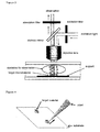
- Figure 2 shows a method to immobilize a target material by locally heating the area surrounding the target material.
- Figure 3 shows an observation method after temporarily immobilizing only the micromaterials near a support material using a method (thermal gelation) of the present invention.
- Figure 4 shows a recovery mode using a pipette after a target material is immobilized using a gel.
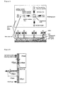
- Figure 5 is a microchip schematic diagram.
- the top figure is a view of the microchip from above, and the lower figure is a cross sectional view.
- Figure 6 is a schematic diagram of another microchip. The microchip was viewed from above.
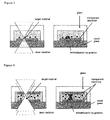
- Figure 8 shows the concentration of a laser on a transparent electrode in Example 3 (figure on the left) and the gelation mode of methylcellulose incorporating a target material (figure on the right).
- a target material is immobilized by a gel and is recovered using a pipette.
- the execution mode of the process is shown in Figure 4.
- a substrate a glass with an electrode (ITO) film formed on the surface
- a target material can be observed using an inverted microscope.
- This substrate was examined using an inverted optical microscope (Olympus Co., IX70), and a target material was selected.
- a particular target was selected from the materials present near the bottom, and the substrate in the vicinity of the target material was irradiated by concentrating an Nd:YVO 4 laser (Spectra-Physics Co., J20-IR-2E, wavelength: 1064 nm) through an objective lens (Olympus Co., UPlanApo 100x/1.35).
- This irradiation locally heated the area surrounding this substrate by the laser, and the target material was immobilized on the substrate since methylcellulose was gelled along with the target material.
- the gel formed by the laser irradiation remained in a gel state for a certain duration of time, therefore multiple numbers of target materials were immobilized at this point.
- microchips are equipped with two intersecting flow channels.
- the form for these two flow channels were created using microtooling, and the microfluid chips were shaped from PDMS (polydimethylsiloxane).
- a single discharge port functioned to discharge both a sample and a cleaning solution.
- One flow channel was used to add a sol/gel phase transition substance containing a target material and to move water used to clean unnecessary materials other than subsequently fixed target materials.
- the other flow channel was used to recover the fixed target material.
- the intersection of the two flow channels was observed using an inverted optical microscope (Olympus Co., IX70), and the zone was irradiated by focusing an Nd:YVO 4 laser (Spectra-Physics Co., J20-IR-2E, wavelength: 1064 nm) through an objective lens (Olympus Co., UPlanApo 100x/1.35).
- a transparent electrode (Matsunami Glass Kogyo K.K., a thin glass sheet with ITO) was formed as a film in the bottom of the observation zone, and a pattern was created. Furthermore, the surface of this transparent electrode was coated using silicon oxide.
- This microchip was positioned on the stage of an optical microscope.
- the stage was movable, and the microchip could be observed using microscope and irradiated using a laser while moving the observation zone.
- the cooled transparent electrode was subsequently warmed to near the thermal gelation initiation temperature but not exceeding it by passing an electrical current, and the vicinity of where two of the microflow channels intersected was observed using an inverted microscope to select a target material.
- the transparent electrode in the vicinity of the target material (the aforementioned sample) was irradiated with the focused laser.
- the transparent electrode in the area exposed was heated, and the methylcellulose in the area was gelled while entrapping the target material.
- the design is shown in Figure 7. Cleaning water was subsequently added from a cleaning water addition port, and methylcellulose and other unnecessary materials not immobilized were removed and discharged through a discharge port.
- the valve on the discharge port was subsequently closed, and a solution containing a sample was added from the addition port.
- a solution containing a sample was added from the addition port.
- a microchip similar to the one described in Example 1 with the exception of having transparent electrodes (ITO) located in top and lower sections of an observation zone was used.
- Both transparent electrodes were warmed by passing electrical current, and the sample and impurities were entirely immobilized once.
- the target material vicinity was subsequently irradiated using a laser in the same manner as described in Example 1.
- the design is shown in Figure 8.
- the power to the transparent electrodes was subsequently terminated, and water was added from a cleaning water addition port to remove unnecessary materials.
- the target material remaining was subsequently recovered.
- One merit of the current method is that a sample not near the bottom surface can be immobilized in the environment since the immobilization occurs through localized heating using bottom and top electrodes.
- a target material was immobilized by heating that combined electrical overheating of an electrode with localized heating using laser irradiation.
- a schematic diagram of this microchip is shown in Figure 9.
- This microchip was positioned on a microscope stage.
- the observation zone could be changed according to the observation magnification of the microscope, and a broad area could be observed by moving the stage.
- a large amount of sample can be treated by preparing multiple numbers of electrodes, and the work efficiency can be improved.
- In order to realize immobilization through electrical overheating of an electrode only one target material of about several microns can be immobilized and, therefore, the number of electrodes needed to be increased. Many electrodes are needed to remove only one target material from several thousands to several tens of thousands of micromaterial samples, and the system could become complex. Therefore, multiple numbers of electrodes that can immobilize several thousands to several tens of thousand of micromaterial samples at once were prepared. In the present example, electrodes A-D, four independent electrodes, were prepared.
- Example 1 The sample from Example 1 was used, appropriate valves were controlled for sample additions, and cleaning and recovery were as in Example 1.
- a micromaterial sample was first added, and electrical current was passed through all electrodes to heat them to immobilize the micromaterial sample. Cleaning water was allowed to flow as needed, and the samples that were not immobilized were washed away. Next, the flow of electricity and the heating of Electrode (A) were terminated, and a target material was decided upon examining the micromaterial sample on Electrode (A). The target material was immobilized through laser irradiation and localized heating. After the immobilization, materials other than the target material in the vicinity of Electrode (A) were washed away using a flow of cleaning water. Electrode (A) was subsequently heated using a flow of electrical current, and the target material previously selected was immobilized before laser irradiation was terminated.
Landscapes
- Chemical & Material Sciences (AREA)
- Health & Medical Sciences (AREA)
- General Health & Medical Sciences (AREA)
- Dispersion Chemistry (AREA)
- Analytical Chemistry (AREA)
- Hematology (AREA)
- Clinical Laboratory Science (AREA)
- Chemical Kinetics & Catalysis (AREA)
- Molecular Biology (AREA)
- Life Sciences & Earth Sciences (AREA)
- Physics & Mathematics (AREA)
- Fluid Mechanics (AREA)
- Apparatus Associated With Microorganisms And Enzymes (AREA)
- Micro-Organisms Or Cultivation Processes Thereof (AREA)
- Immobilizing And Processing Of Enzymes And Microorganisms (AREA)
Abstract
Description
- 1. An electrode is used to heat the solution to T2, a temperature just below the gel formation initiation temperature. At this point, the entire solution is in the form of a sol.
- 2. A solution containing a mixed sample of microorganisms, cells or DNA materials is allowed to flow.
- 3. A laser is used to heat only the area surrounding the target to T4, a temperature exceeding the gel formation initiation temperature to form a gel. The laser is immediately discontinued after the heating. However, the area surrounding the target remains gelled since the temperature once exceeded T4, the gel formation temperature, and remains supported by the bottom surface. The area surrounding a target material may be heated locally without heating the target material itself and the target material may be immobilized on a support material, when direct laser irradiation and direct target material heating using other heating means are not appropriate. An example is shown in Figure 2.
- 4. By repeating step 3, multiple numbers of targets can be maintained over a heating electrode. When microorganisms and cells are targets, the heating electrode may be covered with an insulator in order to avoid killing microorganisms and cells by electricity.
- 5. A cleaning flow is generated to remove the non-target material. The target is fixed on the bottom surface at this point due to the gelled areas and is not moved by the flow. Therefore, only the non-target material is removed.
- 6. Steps 2-5 are repeated, and optional numbers of target materials can be retained.
- 7. The temperature reaches T1 instantaneously when the heating electrode is turned off, and the gelled areas surrounding a target are instantaneously converted into a sol that can move with the flow without adhering to the bottom surface.
- 8. The recovery flow is allowed to move, and the target material is recovered from a recovery port.
In addition, the present invention is a device for recovering micromaterials comprising a space to retain a medium that undergoes a reversible phase transition between a sol and a gel by changing temperature and a support material, means to heat said support material to a temperature of at least the phase transition temperature of said medium, means to heat said support material locally to a temperature of at least the phase transition temperature of said medium, a flow channel through which said medium is added to said space, a flow channel through which a cleaning fluid is added to said space, a flow channel through which the cleaning fluid is discharged from said space and a flow channel through which said medium is discharged from said space. Any one of these flow channels may also function as other flow channels.
Claims (22)
- A method of recovering a desired micromaterial in a system comprising a medium that undergoes a reversible phase transition between a sol and a gel, a support material and micromaterials, comprising the steps of converting the medium surrounding the micromaterial to be recovered into a gel locally to immobilize said micromaterial on said support along with the gelled medium, removing the medium and micromaterials not immobilized on said support material and converting the gelled medium to a sol to recover the micromaterial.
- The method as in claim 1 wherein the medium has a sol to gel phase transition temperature, forms a gel when heated to at or above said phase transition temperature and forms a sol when cooled to at or below said phase transition temperature.
- The method as in claim 2 wherein the phase transition temperature is from room temperature to 90°C.
- The method as in claim 2 or 3 wherein the medium is a water soluble cellulose derivative or a solution thereof.
- The method as in claim 4 wherein the cellulose derivative is methylcellulose.
- The method as in any one of claims 1 to 5 wherein the support material is transparent.
- The method as in claim 6 wherein the support material is a transparent electrode (ITO).
- The method as in any one of claims 1 to 7 wherein the micromaterial has a marker for identification.
- The method as in any one of claims 1 to 7 wherein the micromaterial is a DNA molecule, a cell or a microorganism.
- The method as in any one of claims 2 to 9 wherein the medium is heated to a temperature at or above the phase transition temperature by applying infrared irradiation and the medium is cooled to a temperature at or below the phase transition temperature by terminating the infrared irradiation.
- The method as in claim 10 wherein the means to heat is an infrared laser.
- The method as in claim 11 wherein the infrared laser is a YAG laser or an Nd:YVO4 laser.
- A device for recovering micromaterials comprising a space to retain a medium that undergoes a reversible phase transition between a sol and a gel by changing temperature and a support material, means to heat said support material to a temperature of at least the phase transition temperature of said medium, means to heat said support material locally to a temperature of at least the phase transition temperature of said medium, a flow channel through which said medium is added to said space, a flow channel through which a cleaning fluid is added to said space, a flow channel through which the cleaning fluid is discharged from said space and a flow channel through which said medium is discharged from said space.
- The device as in claim 13 wherein the medium is a water soluble cellulose derivative or a solution thereof.
- The device as in claim 14 wherein the cellulose derivative is methylcellulose.
- The device as in any one of claims 13 to 15 wherein the support material is transparent.
- The device as in claim 16 wherein the support material is a transparent electrode (ITO).
- The device as in any one of claims 13 to 17 the means to heat said support material locally being an infrared irradiation device to irradiate the space.
- The device as in claim 18 wherein the infrared irradiation device is an infrared laser.
- The device as in claim 19 wherein the infrared laser is a YAG laser or an Nd:YVO4 laser.
- The device as in claim 20 further equipped with a lens that concentrates the infrared radiation from an infrared irradiation device to the space.
- The device as in any one of claims 13 to 21 further equipped with a microscope enabling observation of the space.
Applications Claiming Priority (3)
| Application Number | Priority Date | Filing Date | Title |
|---|---|---|---|
| JP2002131656 | 2002-05-07 | ||
| JP2002131656 | 2002-05-07 | ||
| PCT/JP2003/000231 WO2003095088A1 (en) | 2002-05-07 | 2003-01-14 | Method and apparatus for collecting micromaterial |
Publications (3)
| Publication Number | Publication Date |
|---|---|
| EP1504812A1 true EP1504812A1 (en) | 2005-02-09 |
| EP1504812A4 EP1504812A4 (en) | 2006-08-23 |
| EP1504812B1 EP1504812B1 (en) | 2014-01-01 |
Family
ID=29416614
Family Applications (1)
| Application Number | Title | Priority Date | Filing Date |
|---|---|---|---|
| EP03701085.7A Expired - Lifetime EP1504812B1 (en) | 2002-05-07 | 2003-01-14 | Method and apparatus for collecting micromaterial |
Country Status (5)
| Country | Link |
|---|---|
| US (1) | US7824854B2 (en) |
| EP (1) | EP1504812B1 (en) |
| JP (1) | JP4228114B2 (en) |
| CA (1) | CA2476286C (en) |
| WO (1) | WO2003095088A1 (en) |
Cited By (3)
| Publication number | Priority date | Publication date | Assignee | Title |
|---|---|---|---|---|
| WO2009061392A1 (en) * | 2007-11-05 | 2009-05-14 | President And Fellows Of Harvard College | Forming gel structures using microfluidic channels |
| SG153027A1 (en) * | 2007-11-29 | 2009-06-29 | Hitachi Plant Technologies Ltd | Capturing carrier, capturing device, analysis system using the same, and method for capturing and testing microorganisms |
| EP2745936A1 (en) * | 2012-12-21 | 2014-06-25 | Fraunhofer Gesellschaft zur Förderung der angewandten Forschung E.V. | Fluid system with absorbent and reversible polymer gel |
Families Citing this family (14)
| Publication number | Priority date | Publication date | Assignee | Title |
|---|---|---|---|---|
| KR100883775B1 (en) * | 2007-03-22 | 2009-02-18 | 명지대학교 산학협력단 | Electrochemical detector integrated on capillary electrophoresis chip and its manufacturing method |
| JP2009045002A (en) * | 2007-08-20 | 2009-03-05 | Oki Electric Ind Co Ltd | Cell patterning apparatus and cell patterning method |
| WO2009042231A2 (en) * | 2007-09-27 | 2009-04-02 | Akina, Inc. | Sol-gel phase-reversible hydrogel templates and uses thereof |
| JP2010046012A (en) * | 2008-08-21 | 2010-03-04 | Konica Minolta Holdings Inc | Substrate and method for cell culture |
| EP2812669B1 (en) * | 2012-02-10 | 2019-11-27 | Arges GmbH | Laser contrasting method and apparatus for carrying out a contrasting method |
| EP2855695A4 (en) * | 2012-05-29 | 2016-01-13 | Univ California | SYSTEMS, METHODS AND COMPONENTS FOR ISOLATING THE CELLS OF A FLUID SAMPLE |
| KR20180085783A (en) * | 2015-11-23 | 2018-07-27 | 버클리 라잇츠, 인크. | In situ-generated microfluidic isolation structures, kits, and methods of use thereof |
| IL259837B2 (en) * | 2015-12-08 | 2023-03-01 | Berkeley Lights Inc | Microfluidic devices and kits and methods for use thereof |
| MX2023007842A (en) | 2021-01-08 | 2023-09-19 | Cellanome Inc | Devices and methods for analyzing biological samples. |
| US12576399B2 (en) | 2021-01-08 | 2026-03-17 | Cellanome, Inc. | Methods for imaging and analyzing a cell in a compartment of a fluidic device |
| US12576400B2 (en) | 2021-01-08 | 2026-03-17 | Cellanome, Inc. | Methods for incubating and analyzing a cell in a compartment of a fluidic device |
| EP4779305A2 (en) * | 2021-07-13 | 2026-07-22 | 10X Genomics, Inc. | Methods for preparing polymerized matrix with controllable thickness |
| US12661647B2 (en) | 2022-03-22 | 2026-06-23 | Cellanome, Inc. | Methods for enclosing and analyzing a cell in a fluidic device |
| US12669417B2 (en) | 2022-03-28 | 2026-06-30 | Bruker Spatial Biology, Inc. | Method for assaying a micro-object within a microfluidic device |
Family Cites Families (20)
| Publication number | Priority date | Publication date | Assignee | Title |
|---|---|---|---|---|
| US4689102A (en) * | 1985-01-25 | 1987-08-25 | Technographics Fitchburg Coated Products, Inc. | Method for the production of abrasion-resistant decorative laminates |
| US5134070A (en) * | 1990-06-04 | 1992-07-28 | Casnig Dael R | Method and device for cell cultivation on electrodes |
| US5632957A (en) * | 1993-11-01 | 1997-05-27 | Nanogen | Molecular biological diagnostic systems including electrodes |
| JP3359370B2 (en) * | 1993-03-17 | 2002-12-24 | 光弘 清水 | Electrophoresis gel for separation and recovery and separation and recovery method using the same |
| WO1994029069A1 (en) * | 1993-06-04 | 1994-12-22 | Seiko Epson Corporation | Apparatus and method for laser machining, and liquid crystal panel |
| JP3414444B2 (en) | 1993-06-08 | 2003-06-09 | 倭 窪田 | Immobilization device, method for immobilizing and culturing biological tissue using the same |
| JPH089966A (en) * | 1994-06-30 | 1996-01-16 | Sumitomo Bakelite Co Ltd | Method for transporting animal cell |
| DE69735411T2 (en) * | 1996-10-09 | 2006-09-07 | Symyx Technologies, Inc., Santa Clara | INFRARED SPECTROSCOPY AND LIBRARY IMAGING |
| WO1999036576A1 (en) * | 1998-01-20 | 1999-07-22 | Packard Bioscience Company | Gel pad arrays and methods and systems for making them |
| JPH11210750A (en) | 1998-01-29 | 1999-08-03 | Koyo Seiko Co Ltd | Control type magnetic bearing device |
| US6103528A (en) * | 1998-04-17 | 2000-08-15 | Battelle Memorial Institute | Reversible gelling culture media for in-vitro cell culture in three-dimensional matrices |
| US6139831A (en) * | 1998-05-28 | 2000-10-31 | The Rockfeller University | Apparatus and method for immobilizing molecules onto a substrate |
| JPH11346756A (en) | 1998-06-09 | 1999-12-21 | Moritex Corp | Cell plate for micro sample separation |
| US6093370A (en) * | 1998-06-11 | 2000-07-25 | Hitachi, Ltd. | Polynucleotide separation method and apparatus therefor |
| EP1214630A2 (en) * | 1999-07-23 | 2002-06-19 | The Board Of Trustees Of The University Of Illinois | Microfabricated devices and method of manufacturing the same |
| JP2001095558A (en) | 1999-07-26 | 2001-04-10 | Moritex Corp | Cell plate for micro sample separation |
| JP3542534B2 (en) | 1999-11-19 | 2004-07-14 | 株式会社東海理化電機製作所 | Micro sample separation unit |
| WO2001070022A1 (en) * | 2000-03-21 | 2001-09-27 | Yuichi Mori | Coating materials for biological tissues, coated biological tissues and method of coating biological tissues |
| JP3628611B2 (en) * | 2000-11-29 | 2005-03-16 | 独立行政法人科学技術振興機構 | Flow control method in micro system |
| JP2003102465A (en) * | 2001-09-27 | 2003-04-08 | Precision System Science Co Ltd | Target substance separation method |
-
2003
- 2003-01-14 JP JP2004503162A patent/JP4228114B2/en not_active Expired - Fee Related
- 2003-01-14 CA CA002476286A patent/CA2476286C/en not_active Expired - Fee Related
- 2003-01-14 EP EP03701085.7A patent/EP1504812B1/en not_active Expired - Lifetime
- 2003-01-14 US US10/508,639 patent/US7824854B2/en not_active Expired - Fee Related
- 2003-01-14 WO PCT/JP2003/000231 patent/WO2003095088A1/en not_active Ceased
Cited By (5)
| Publication number | Priority date | Publication date | Assignee | Title |
|---|---|---|---|---|
| WO2009061392A1 (en) * | 2007-11-05 | 2009-05-14 | President And Fellows Of Harvard College | Forming gel structures using microfluidic channels |
| SG153027A1 (en) * | 2007-11-29 | 2009-06-29 | Hitachi Plant Technologies Ltd | Capturing carrier, capturing device, analysis system using the same, and method for capturing and testing microorganisms |
| US8628953B2 (en) | 2007-11-29 | 2014-01-14 | Hitachi Plant Technologies, Ltd. | Capturing carrier, capturing device, analysis system using the same, and method for capturing and testing microorganisms |
| EP2745936A1 (en) * | 2012-12-21 | 2014-06-25 | Fraunhofer Gesellschaft zur Förderung der angewandten Forschung E.V. | Fluid system with absorbent and reversible polymer gel |
| US10782213B2 (en) | 2012-12-21 | 2020-09-22 | Diamond Invention Ug | Fluidic system |
Also Published As
| Publication number | Publication date |
|---|---|
| WO2003095088A1 (en) | 2003-11-20 |
| CA2476286A1 (en) | 2003-11-20 |
| JP4228114B2 (en) | 2009-02-25 |
| EP1504812B1 (en) | 2014-01-01 |
| CA2476286C (en) | 2008-03-18 |
| EP1504812A4 (en) | 2006-08-23 |
| JPWO2003095088A1 (en) | 2005-09-08 |
| US7824854B2 (en) | 2010-11-02 |
| US20050208465A1 (en) | 2005-09-22 |
Similar Documents
| Publication | Publication Date | Title |
|---|---|---|
| US7824854B2 (en) | Method or apparatus for recovering micromaterial | |
| US6824664B1 (en) | Electrode-less dielectrophorises for polarizable particles | |
| US7524672B2 (en) | Microfluidic microarray systems and methods thereof | |
| US6660480B2 (en) | Method for analyzing nucleic acids by means of a substrate having a microchannel structure containing immobilized nucleic acid probes | |
| JP5222723B2 (en) | Apparatus and method for analyzing individual cells | |
| US6361953B1 (en) | Cell component recovery method | |
| DE69232181T2 (en) | Thermal cycle device | |
| JP4171775B2 (en) | Nucleic acid analyzer | |
| WO2001037958A2 (en) | Electrodeless dielectrophoresis for polarizable particles | |
| US20050208539A1 (en) | Quantitative amplification and detection of small numbers of target polynucleotides | |
| US5972667A (en) | Method and apparatus for activating a thermo-enzyme reaction with electromagnetic energy | |
| WO2012178166A1 (en) | Method and apparatus for fractionating genetically distinct cells and cellular components | |
| JP2009503555A (en) | Multi-channel flow cell | |
| Maruyama et al. | Immobilization of individual cells by local photo-polymerization on a chip | |
| JP4216018B2 (en) | Nucleic acid recovery chip and nucleic acid recovery device | |
| JP3877164B2 (en) | Fixing method of minute objects | |
| JP4446486B2 (en) | Fixing method of minute objects | |
| Brennan et al. | A hybrid approach to device integration on a genetic analysis platform | |
| JP2018091634A (en) | Sample treatment method and kit for sample treatment | |
| Maruyama et al. | Microfabrication of functional microtool using photo-crosslinkable resin | |
| Maruyama et al. | Laser Manipulation and Fabrication of Functional Microtool Using Photo-crosslinkable Resin |
Legal Events
| Date | Code | Title | Description |
|---|---|---|---|
| PUAI | Public reference made under article 153(3) epc to a published international application that has entered the european phase |
Free format text: ORIGINAL CODE: 0009012 |
|
| 17P | Request for examination filed |
Effective date: 20040818 |
|
| AK | Designated contracting states |
Kind code of ref document: A1 Designated state(s): AT BE BG CH CY CZ DE DK EE ES FI FR GB GR HU IE IT LI LU MC NL PT SE SI SK TR |
|
| RIN1 | Information on inventor provided before grant (corrected) |
Inventor name: KATSURAGI, TOHORU Inventor name: ICHIKAWA, AKIHIKO Inventor name: ARAI, FUMIHITO Inventor name: FUKUDA, TOSHIO |
|
| RBV | Designated contracting states (corrected) |
Designated state(s): CH DE FR GB LI NL SE |
|
| A4 | Supplementary search report drawn up and despatched |
Effective date: 20060720 |
|
| 17Q | First examination report despatched |
Effective date: 20100608 |
|
| GRAP | Despatch of communication of intention to grant a patent |
Free format text: ORIGINAL CODE: EPIDOSNIGR1 |
|
| INTG | Intention to grant announced |
Effective date: 20130819 |
|
| GRAS | Grant fee paid |
Free format text: ORIGINAL CODE: EPIDOSNIGR3 |
|
| GRAA | (expected) grant |
Free format text: ORIGINAL CODE: 0009210 |
|
| AK | Designated contracting states |
Kind code of ref document: B1 Designated state(s): CH DE FR GB LI NL SE |
|
| REG | Reference to a national code |
Ref country code: GB Ref legal event code: FG4D |
|
| REG | Reference to a national code |
Ref country code: CH Ref legal event code: EP |
|
| REG | Reference to a national code |
Ref country code: NL Ref legal event code: T3 |
|
| REG | Reference to a national code |
Ref country code: DE Ref legal event code: R096 Ref document number: 60345540 Country of ref document: DE Effective date: 20140220 |
|
| REG | Reference to a national code |
Ref country code: CH Ref legal event code: NV Representative=s name: FREI PATENTANWALTSBUERO AG, CH Ref country code: SE Ref legal event code: TRGR |
|
| PGFP | Annual fee paid to national office [announced via postgrant information from national office to epo] |
Ref country code: DE Payment date: 20140211 Year of fee payment: 12 Ref country code: NL Payment date: 20140129 Year of fee payment: 12 Ref country code: CH Payment date: 20140131 Year of fee payment: 12 |
|
| PGFP | Annual fee paid to national office [announced via postgrant information from national office to epo] |
Ref country code: FR Payment date: 20140228 Year of fee payment: 12 |
|
| PGFP | Annual fee paid to national office [announced via postgrant information from national office to epo] |
Ref country code: GB Payment date: 20140206 Year of fee payment: 12 |
|
| REG | Reference to a national code |
Ref country code: DE Ref legal event code: R097 Ref document number: 60345540 Country of ref document: DE |
|
| PLBE | No opposition filed within time limit |
Free format text: ORIGINAL CODE: 0009261 |
|
| STAA | Information on the status of an ep patent application or granted ep patent |
Free format text: STATUS: NO OPPOSITION FILED WITHIN TIME LIMIT |
|
| 26N | No opposition filed |
Effective date: 20141002 |
|
| REG | Reference to a national code |
Ref country code: DE Ref legal event code: R097 Ref document number: 60345540 Country of ref document: DE Effective date: 20141002 |
|
| REG | Reference to a national code |
Ref country code: DE Ref legal event code: R119 Ref document number: 60345540 Country of ref document: DE |
|
| REG | Reference to a national code |
Ref country code: NL Ref legal event code: V1 Effective date: 20150801 |
|
| REG | Reference to a national code |
Ref country code: CH Ref legal event code: PL |
|
| REG | Reference to a national code |
Ref country code: SE Ref legal event code: EUG |
|
| GBPC | Gb: european patent ceased through non-payment of renewal fee |
Effective date: 20150114 |
|
| PG25 | Lapsed in a contracting state [announced via postgrant information from national office to epo] |
Ref country code: NL Free format text: LAPSE BECAUSE OF NON-PAYMENT OF DUE FEES Effective date: 20150801 |
|
| PG25 | Lapsed in a contracting state [announced via postgrant information from national office to epo] |
Ref country code: DE Free format text: LAPSE BECAUSE OF NON-PAYMENT OF DUE FEES Effective date: 20150801 Ref country code: GB Free format text: LAPSE BECAUSE OF NON-PAYMENT OF DUE FEES Effective date: 20150114 Ref country code: CH Free format text: LAPSE BECAUSE OF NON-PAYMENT OF DUE FEES Effective date: 20150131 Ref country code: LI Free format text: LAPSE BECAUSE OF NON-PAYMENT OF DUE FEES Effective date: 20150131 |
|
| REG | Reference to a national code |
Ref country code: FR Ref legal event code: ST Effective date: 20150930 |
|
| PG25 | Lapsed in a contracting state [announced via postgrant information from national office to epo] |
Ref country code: FR Free format text: LAPSE BECAUSE OF NON-PAYMENT OF DUE FEES Effective date: 20150202 Ref country code: SE Free format text: LAPSE BECAUSE OF NON-PAYMENT OF DUE FEES Effective date: 20150115 |
|
| REG | Reference to a national code |
Ref country code: DE Ref legal event code: R082 Ref document number: 60345540 Country of ref document: DE Representative=s name: WUNDERLICH & HEIM PATENTANWAELTE PARTNERSCHAFT, DE |