EP1504720A1 - Modular patient support system for use in radiotherapy treatments - Google Patents
Modular patient support system for use in radiotherapy treatments Download PDFInfo
- Publication number
- EP1504720A1 EP1504720A1 EP04077064A EP04077064A EP1504720A1 EP 1504720 A1 EP1504720 A1 EP 1504720A1 EP 04077064 A EP04077064 A EP 04077064A EP 04077064 A EP04077064 A EP 04077064A EP 1504720 A1 EP1504720 A1 EP 1504720A1
- Authority
- EP
- European Patent Office
- Prior art keywords
- modular
- basic portion
- modular system
- radiotransparent
- pins
- Prior art date
- Legal status (The legal status is an assumption and is not a legal conclusion. Google has not performed a legal analysis and makes no representation as to the accuracy of the status listed.)
- Granted
Links
- 238000011282 treatment Methods 0.000 title claims abstract description 10
- 238000001959 radiotherapy Methods 0.000 title claims abstract description 5
- 230000008878 coupling Effects 0.000 claims abstract description 3
- 238000010168 coupling process Methods 0.000 claims abstract description 3
- 238000005859 coupling reaction Methods 0.000 claims abstract description 3
- OKTJSMMVPCPJKN-UHFFFAOYSA-N Carbon Chemical compound [C] OKTJSMMVPCPJKN-UHFFFAOYSA-N 0.000 claims description 14
- 229910052799 carbon Inorganic materials 0.000 claims description 14
- 206010028980 Neoplasm Diseases 0.000 claims description 7
- 210000000038 chest Anatomy 0.000 claims description 5
- 230000000295 complement effect Effects 0.000 claims description 4
- 239000006261 foam material Substances 0.000 claims description 4
- 239000000463 material Substances 0.000 claims description 4
- 210000004197 pelvis Anatomy 0.000 claims description 4
- 210000004072 lung Anatomy 0.000 claims 1
- 230000005855 radiation Effects 0.000 description 9
- 239000002184 metal Substances 0.000 description 5
- 238000005452 bending Methods 0.000 description 4
- 239000000835 fiber Substances 0.000 description 4
- 230000001678 irradiating effect Effects 0.000 description 4
- 239000003822 epoxy resin Substances 0.000 description 3
- 229920000647 polyepoxide Polymers 0.000 description 3
- 238000009825 accumulation Methods 0.000 description 1
- 230000006978 adaptation Effects 0.000 description 1
- 238000002591 computed tomography Methods 0.000 description 1
- 238000010276 construction Methods 0.000 description 1
- 230000000694 effects Effects 0.000 description 1
- 238000005457 optimization Methods 0.000 description 1
- 230000002787 reinforcement Effects 0.000 description 1
- 230000003313 weakening effect Effects 0.000 description 1
Images



Classifications
-
- A—HUMAN NECESSITIES
- A61—MEDICAL OR VETERINARY SCIENCE; HYGIENE
- A61B—DIAGNOSIS; SURGERY; IDENTIFICATION
- A61B6/00—Apparatus or devices for radiation diagnosis; Apparatus or devices for radiation diagnosis combined with radiation therapy equipment
- A61B6/04—Positioning of patients; Tiltable beds or the like
- A61B6/0407—Supports, e.g. tables or beds, for the body or parts of the body
- A61B6/0442—Supports, e.g. tables or beds, for the body or parts of the body made of non-metallic materials
-
- A—HUMAN NECESSITIES
- A61—MEDICAL OR VETERINARY SCIENCE; HYGIENE
- A61B—DIAGNOSIS; SURGERY; IDENTIFICATION
- A61B6/00—Apparatus or devices for radiation diagnosis; Apparatus or devices for radiation diagnosis combined with radiation therapy equipment
- A61B6/44—Constructional features of apparatus for radiation diagnosis
- A61B6/4411—Constructional features of apparatus for radiation diagnosis the apparatus being modular
-
- A—HUMAN NECESSITIES
- A61—MEDICAL OR VETERINARY SCIENCE; HYGIENE
- A61N—ELECTROTHERAPY; MAGNETOTHERAPY; RADIATION THERAPY; ULTRASOUND THERAPY
- A61N5/00—Radiation therapy
- A61N5/10—X-ray therapy; Gamma-ray therapy; Particle-irradiation therapy
Definitions
- the present invention relates to a modular patient support system for use in radiotherapy treatments, at least comprising a radiotransparent structure.
- Such patient supports are known in various embodiments and are substantially intended for being mounted on adjustable tables belonging to an arrangement with irradiation apparatus.
- rigidity and radiotransparency of said support is of great importance.
- at least a part of the structure comprises metal parts providing rigidity and/or fixation possibilities of accessories. These metal parts cause scatter of the radiation beam. Therefore, with the current patient supports it should always be possible to irradiate past the metal parts. Due to this, it is not possible to irradiate a patient across any desired angle.
- current supports are often wide, for the purpose of being able to perform all treatments on one patient support and to have enough space to be able to irradiate past said metal parts. This width of the support hinders the number of degrees of freedom of the irradiating member.
- the object of the invention is to provide a modular patient support system having exchangeable modular parts, projecting freely, being sufficiently rigid and fully radiotransparent.
- a further object is to provide an adapted modular part for each specific treatment.
- the patient support system comprises a basic portion to be mounted fixedly and an exchangeable radiotransparent modular portion, said basic portion to be mounted fixedly being provided with a radiotransparent supporting part for supporting an exchangeable modular part and means being provided for positioning said modular portion in relation to the basic portion and for coupling it to said basic portion.
- the basic portion is intended for being fixedly mounted onto an adjustable table belonging to irradiation equipment and therefore need not have any special radiotransparent properties.
- the supporting portion projecting from said basic portion projects out of the basic portion from approximately the table edge and will be situated completely or partly within the range of the irradiation equipment.
- the modular portion to be situated onto the supporting portion is a sandwich structure made of the materials commonly used for it, such as for example layers of oriented fibres, e.g. carbon fibres, said fibres being embedded in an epoxy resin, and a foam material or a honeycomb structure.
- the modular system according to the invention has the further advantages that with the radiotransparent supporting portion, the modular portion can be made smaller than is usual with said known patient supports.
- the metal reinforcements must be kept outside the range to be irradiated, therefore outside of the body contour of the patients to be treated.
- the advantages of a less wide support are, among other things, that the irradiating member can be brought closer to the tumors to be treated and that the entity of fixed basic portion and modular portion can be positioned within a larger range in relation to said radiating member.
- the positioning range is limited because of the dimensions of said entity. Therefore, the radiating member will easily abut the support or the support will easily abut the stationary parts of the irradiation device.
- a further advantage is that the specific modular portions can be made for irradiating tumors in specific target areas, to which end the modular portions can be adapted in shape.
- the modular patient support can be made narrower than usual, as a result of which more adjusting possibilities are provided. This also enables a more effective irradiation and conservation of a greater amount of healthy tissue. Since the modular portions are intended for a certain target area, they can be provided with speciale fixing positions for accessories to be used.
- the patient mostly passes through the CT scanning device, where the tumor(s) is/will be located.
- an irradiation planning is made.
- a great advantage is achieved by providing the CT scanner with a patient support which corresponds to the patient support according to the invention as far as positioning of the patient, dosimetric properties and markers are concerned.
- the previously required calculating operations of the CT support to the form and dosimetric properties of the patient support in the irradiating device can be omitted. This makes planning the irradiation much quicker, more effective and reliable and positioning of the patient is much more accurate and better reproducible. This again leads to a more accurate and more effective irradiation of the tumor.
- the radiotransparent supporting portion of said fixed basic portion substantially comprises spaced-apart arms extending in longitudinal direction of said basic portion, having their ends connected to one another by a connecting part.
- the arms of said radiotransparent supporting portion comprise tubular sleeves, their lower and upper sides comprising a hybrid structure of one directional carbon fibres and cross-woven carbon fibres.
- the one-directional carbon fibres preferably have a great stiffness and further, the carbon fibres are embedded in epoxy resin.
- At least one side of the tubular sleeve has across a part of its length a sandwich structure having a core of foam material and at both sides a layer of carbon fibres. More in particular, this layer comprises cross-woven carbon fibre embedded in epoxy resin.
- This structure of the supporting profiles is a weighted optimization between strength and stiffness requirements and the dosimetric requirements.
- the dosimetric properties are especially important at the sides, since they cover a much larger rotational angle of the irradiation member than the bottom and top sides of the tubular sleeves per se do.
- the dosimectric properties directly depend on the specific density and the properties of the material passed by the radiation.
- tubular sleeves seen in cross-section, become narrower from the upwardly situated plane of contact with a modular part downwards.
- a preferred embodiment provides for, that the tubular sleeves have an obliquely extending plane at the outwardly facing sides.
- the modular portion and the fixed basic portion are provided with positioning means and means for having the modular portion engage the fixed basic portion with a snap connection.
- first positioning means comprising one or more slides mounted on the extreme end of a modular portion and holes corresponding to them for receiving the pins in the extreme end of the fixed basic portion.
- the slides have adjusting means for being able to set a modular portion in a desired position in relation to the fixed basic portion.
- second positioning means comprising one or more pins mounted on a modular portion, said pins being made of a radiotransparent material, and corresponding holes for receiving the pins in the radiotransparent supporting portion of the fixed basic portion.
- the pins preferably form a whole with the modular portion.
- the holes for receiving the pins are preferably in the form of bushes mounted in the connecting part through which the extreme ends of the tubular sleeves are connected to one another, in which said bushes can extend into the tubular sleeves.
- the respective bushes can be a whole with the connecting part and a tubular sleeve.
- one or more snap connection members are applied between modular portion and fixed basic portion.
- the part of said snap connection members on the modular portion are preferably mounted on the extreme ends of the pins of first positioning means. In this way, when assembling basic portion and modular portion, said snap connection members will be situated in the basic portion completely and thus the snap connection members need not be radiotransparent.
- Figs. 1, 2 show schematically an arrangement of an irradiation device 1 having an radiating member 2 that can be rotated around a horizontal shaft 3. In this way, the radiating member can be brought into any position in relation to a patient to be irradiated within a range of 360° and therefore in any series of subsequent positions.
- a patient to be treated is supported by a support 4.
- the support 4 is mounted on an adjustable table 5, which is rotatable around twee vertical axes 6, 6' and is adjustable in heigth and in which the adjustable table 5 can move the support 4 horizontally and laterally. In this way, the tumor to be treated of a patient can be positioned exactly in the radiation centre of radiating member 2.
- the support 4 comprises a basic portion 7 fixedly applied on the table 5 and a modular portion 8 coupled to said basic portion.
- Figs. 3, 4 show respectively a plan view and a perspective bottom view of said basic portion 7 of support 4.
- the basic portion comprises a flat plate 9 and a supporting part 10 projecting from it, which is intended for supporting modular portions 8.
- Supporting part 10 is comprised of radiotransparent supporting arms 11, 12 having their extreme ends connected through a likewise radiotransparent connecting piece 13.
- Plate 9 has its bottom side provided with means for attachment to an adjustable table 5 belonging to an irradiation device 1.
- the means comprise a hole 14 for receiving a pin not further illustrated in the drawing, on the adjustable table 5, mounting profile 16 at the rear end and adjusting plates 17, 18, 19 for aligning said plate 9.
- fixing cams 20 At the sides of the plate 9 fixing cams 20 have been mounted for securing auxiliary means.
- openings 21, 22 for receiving first positioning elements, slides 23, 24 at the extreme end of a modular portion 8.
- Said openings 21, 22 also contain the complementary parts of said snap connection members 25, 26 (see fig. 7) mounted at the extreme ends of respective first positioning elements 23, 24.
- Fig. 5 shows a cross-section of a supporting arm 11, 12.
- the top and bottom sides 31, 32 substantially comprise a hybrid structure having a number of fibre layers, such as carbon fibre layers, for example.
- the carbon fibres can be oriented in substantially one direction, the longitudinal direction or the fibres can be woven in a crossed relation.
- the sides 33, 34 comprise a sandwich structure having fibre layers, e.g. layers of cross-woven carbon fibres, having a core of a foam material 35, 36. This structure is strong enough to minimize bending of the supporting arms 11, 12.
- the outside 33 has a portion 37 extending straigth and an angled portion 38, as a result of which the radiation member can be led closer along the patient support.
- Fig. 6 shows an assembly of the basic portion 7 with plate 9 and supporting portion 10 and a modular portion 8.
- Said modular portion 8 is identical to the modular portion shown in fig. 7 and is especially intended for treating the area of head and neck.
- Modular portion 8 has its positioning elements, the slides 23, 24 projecting into the openings 21, 22 (see also fig. 8) and positioning pins 29, 30 into the holes 27, 28.
- the complementary parts of the snap connection members 25, 26 are engaging.
- the snap connecting members are preferably of the type in which bringing the parts in and out of engagement occurs by applying a force which is greater than a predetermined threshold value. Due to this, a module is easily mountable and removable.
- Figs. 6, 7 show that positioning pins 29, 30 are oriented in parallel to the lower surface of modular portion 8 and are connected to it through adapters 39, 40.
- Pins 29, 30, adapters 39, 40 and the modular portion 8 are an entity which is also radiotransparent in its entirety.
- Modular portion 8 is provided with fixation points 20 for accessories for positioning and fixating the head-neck area.
- Fig. 9 shows a cross-section through a supporting arm 11 and a modular portion 48.
- Modular portion 48 is specially intended for treating tumors in the thorax or pelvic area and is clearly longer than the modular portion meant for treatments in the head-neck areas.
- fixation cams 20 At the sides of modular portion 48, fixation cams 20 have been mounted for accessories intended for positioning the pelvic or thorax area.
- bending at the free extreme end with a 70 kg load at the extreme end proves to be 1 cm maximum.
- the degree of bending is much smaller and in the area where the treatment takes place, close to basic portion 7, the degree of bending is well within the margin for being able to perform an accurate treatment.
- Fig. 11 provides three views of long modular portion 48.
- Fig. 10 shows the first positioning elements, the slides 23, 24, in more detail.
- the top side and at least one side mounts adjusting plates 41, 42 by which an exact adjustment in horizontal and vertical direction, respectively, is possible as well as an exact fit in the openings 21, 22.
- the extreme ends of the slides 23, 24 mount hooks 43, 44 being part of snap connection members 25, 26 known per se.
- the complementary portions are spring-loaded and are designed to enclose the hooks 43, 44 on inserting modular portion 8. It is important that by this, an exact positioning of the fixed basic portion 7 and a modular portion in relation to one another can be effected, which will not show any deviations even with frequent use.
- the modular system according to the invention having a fixed basic portion and a modular portion to be coupled to it is extremely well suitable for developing further modular portions for specific purposes.
- very specific adaptations come within reach, which can not be realized with the existing patient supports for technical or economical reasons.
Landscapes
- Health & Medical Sciences (AREA)
- Life Sciences & Earth Sciences (AREA)
- Medical Informatics (AREA)
- Engineering & Computer Science (AREA)
- Radiology & Medical Imaging (AREA)
- Molecular Biology (AREA)
- Biophysics (AREA)
- Nuclear Medicine, Radiotherapy & Molecular Imaging (AREA)
- Optics & Photonics (AREA)
- Pathology (AREA)
- Physics & Mathematics (AREA)
- Biomedical Technology (AREA)
- Heart & Thoracic Surgery (AREA)
- High Energy & Nuclear Physics (AREA)
- Surgery (AREA)
- Animal Behavior & Ethology (AREA)
- General Health & Medical Sciences (AREA)
- Public Health (AREA)
- Veterinary Medicine (AREA)
- Accommodation For Nursing Or Treatment Tables (AREA)
- Radiation-Therapy Devices (AREA)
Abstract
Description
- The present invention relates to a modular patient support system for use in radiotherapy treatments, at least comprising a radiotransparent structure.
- Such patient supports are known in various embodiments and are substantially intended for being mounted on adjustable tables belonging to an arrangement with irradiation aparatus. With a patient support intended for radiotherapy ) treatments, rigidity and radiotransparency of said support is of great importance. In all current patient supports, at least a part of the structure comprises metal parts providing rigidity and/or fixation possibilities of accessories. These metal parts cause scatter of the radiation beam. Therefore, with the current patient supports it should always be possible to irradiate past the metal parts. Due to this, it is not possible to irradiate a patient across any desired angle. Further, current supports are often wide, for the purpose of being able to perform all treatments on one patient support and to have enough space to be able to irradiate past said metal parts. This width of the support hinders the number of degrees of freedom of the irradiating member.
- The object of the invention is to provide a modular patient support system having exchangeable modular parts, projecting freely, being sufficiently rigid and fully radiotransparent. A further object is to provide an adapted modular part for each specific treatment.
- Accordingly, the invention provides for that the patient support system comprises a basic portion to be mounted fixedly and an exchangeable radiotransparent modular portion, said basic portion to be mounted fixedly being provided with a radiotransparent supporting part for supporting an exchangeable modular part and means being provided for positioning said modular portion in relation to the basic portion and for coupling it to said basic portion. The basic portion is intended for being fixedly mounted onto an adjustable table belonging to irradiation equipment and therefore need not have any special radiotransparent properties. The supporting portion projecting from said basic portion projects out of the basic portion from approximately the table edge and will be situated completely or partly within the range of the irradiation equipment. The modular portion to be situated onto the supporting portion is a sandwich structure made of the materials commonly used for it, such as for example layers of oriented fibres, e.g. carbon fibres, said fibres being embedded in an epoxy resin, and a foam material or a honeycomb structure.
- Apart from the advantage of a completely radiotransparent support, the modular system according to the invention has the further advantages that with the radiotransparent supporting portion, the modular portion can be made smaller than is usual with said known patient supports. With the known structures, the metal reinforcements must be kept outside the range to be irradiated, therefore outside of the body contour of the patients to be treated. The advantages of a less wide support are, among other things, that the irradiating member can be brought closer to the tumors to be treated and that the entity of fixed basic portion and modular portion can be positioned within a larger range in relation to said radiating member. With the known supports, the positioning range is limited because of the dimensions of said entity. Therefore, the radiating member will easily abut the support or the support will easily abut the stationary parts of the irradiation device.
- A further advantage is that the specific modular portions can be made for irradiating tumors in specific target areas, to which end the modular portions can be adapted in shape. The modular patient support can be made narrower than usual, as a result of which more adjusting possibilities are provided. This also enables a more effective irradiation and conservation of a greater amount of healthy tissue. Since the modular portions are intended for a certain target area, they can be provided with speciale fixing positions for accessories to be used.
- Preceding the actual irradiation, the patient mostly passes through the CT scanning device, where the tumor(s) is/will be located. Using this information, an irradiation planning is made. A great advantage is achieved by providing the CT scanner with a patient support which corresponds to the patient support according to the invention as far as positioning of the patient, dosimetric properties and markers are concerned. The previously required calculating operations of the CT support to the form and dosimetric properties of the patient support in the irradiating device can be omitted. This makes planning the irradiation much quicker, more effective and reliable and positioning of the patient is much more accurate and better reproducible. This again leads to a more accurate and more effective irradiation of the tumor.
- According to a further development it is provided for that the radiotransparent supporting portion of said fixed basic portion substantially comprises spaced-apart arms extending in longitudinal direction of said basic portion, having their ends connected to one another by a connecting part. Here, the arms of said radiotransparent supporting portion comprise tubular sleeves, their lower and upper sides comprising a hybrid structure of one directional carbon fibres and cross-woven carbon fibres. The one-directional carbon fibres preferably have a great stiffness and further, the carbon fibres are embedded in epoxy resin. At least one side of the tubular sleeve has across a part of its length a sandwich structure having a core of foam material and at both sides a layer of carbon fibres. More in particular, this layer comprises cross-woven carbon fibre embedded in epoxy resin. This structure of the supporting profiles is a weighted optimization between strength and stiffness requirements and the dosimetric requirements.
- The dosimetric properties are especially important at the sides, since they cover a much larger rotational angle of the irradiation member than the bottom and top sides of the tubular sleeves per se do. The dosimectric properties directly depend on the specific density and the properties of the material passed by the radiation. By the specific construction of the profiles it is achieved that the beam of radiation is weakened as little as possible and an effect of accumulation of radiation on the skin is minimized, while the strength and stiffness of said profiles remains guaranteed.
- According to a yet further development, it is provided that the tubular sleeves, seen in cross-section, become narrower from the upwardly situated plane of contact with a modular part downwards. A preferred embodiment provides for, that the tubular sleeves have an obliquely extending plane at the outwardly facing sides. Thus, the stiffness and strength of the supporting arms can remain guaranteed, while a larger degree of free movement of the radiation member enhances its number of adjusting possibilities.
- In the modular system according to the invention it is important that the modular portion and the fixed basic portion can be properly positioned and secured in relation to one another. To that end, the modular portion and the fixed basic portion are provided with positioning means and means for having the modular portion engage the fixed basic portion with a snap connection.
- According to a first development, first positioning means are provided, comprising one or more slides mounted on the extreme end of a modular portion and holes corresponding to them for receiving the pins in the extreme end of the fixed basic portion. In order to achieve an exact positioning as well as a proper fit of the slides in the holes, it is further provided for, that the slides have adjusting means for being able to set a modular portion in a desired position in relation to the fixed basic portion.
- In order to establish an accurate positioning which will be exactly reproduced again on renewed placement of a modular portion, it is necessary to mount positioning means in the radiotransparent portion of the support as well. According to a further development, to that end, second positioning means are provided, comprising one or more pins mounted on a modular portion, said pins being made of a radiotransparent material, and corresponding holes for receiving the pins in the radiotransparent supporting portion of the fixed basic portion. These second positioning means prevent the modular portion from moving in the remaining level of freedom, therefore in vertical direction, and also serve for transmit the forces exerted on the modular portion to the supporting portion, as a result of which said first positioning means are relieved from force.
- The pins preferably form a whole with the modular portion. The holes for receiving the pins are preferably in the form of bushes mounted in the connecting part through which the extreme ends of the tubular sleeves are connected to one another, in which said bushes can extend into the tubular sleeves. The respective bushes can be a whole with the connecting part and a tubular sleeve.
- Further, according to the invention it is provided for that one or more snap connection members are applied between modular portion and fixed basic portion. The part of said snap connection members on the modular portion are preferably mounted on the extreme ends of the pins of first positioning means. In this way, when assembling basic portion and modular portion, said snap connection members will be situated in the basic portion completely and thus the snap connection members need not be radiotransparent.
- The invention is further explained by way of the example illustrated in the drawing, in which:
- fig. 1
- shows a perspective view of an irradiation device having a fixed basic portion mounted on an adjustable table and a modular portion coupled to it;
- fig. 2
- shows the arrangement of fig. 1 in another position;
- fig. 3
- shows a plan view of the basic portion;
- fig. 4
- shows a perspective bottom view of the basic portion;
- fig. 5
- shows a cross-section of a supporting arm of said basic portion;
- fig. 6
- shows a perspective bottom view of the basic portion and a modular portion coupled to it;
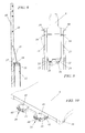
- figs.7A,B,C
- show three views of a module intended for treating the areas of head and neck;
- fig. 8
- shows a bottom view of the basic portion and a module coupled to it, intended for treating the areas of head and neck;
- fig. 9
- shows a cross-section of the basic portion and a module coupled to it, intended for treating the areas of thorax and pelvis;
- fig. 10
- shows a perspective view of the part of the snap connection members mounted on a modular portion; and
- figs.11A,B,C
- show three views of a module intended for treating the areas of thorax and pelvis.
- Figs. 1, 2 show schematically an arrangement of an
irradiation device 1 having an radiatingmember 2 that can be rotated around ahorizontal shaft 3. In this way, the radiating member can be brought into any position in relation to a patient to be irradiated within a range of 360° and therefore in any series of subsequent positions. - A patient to be treated is supported by a
support 4. Thesupport 4 is mounted on an adjustable table 5, which is rotatable around tweevertical axes 6, 6' and is adjustable in heigth and in which the adjustable table 5 can move thesupport 4 horizontally and laterally. In this way, the tumor to be treated of a patient can be positioned exactly in the radiation centre of radiatingmember 2. Thesupport 4 comprises abasic portion 7 fixedly applied on the table 5 and amodular portion 8 coupled to said basic portion. - Figs. 3, 4 show respectively a plan view and a perspective bottom view of said
basic portion 7 ofsupport 4. The basic portion comprises aflat plate 9 and a supportingpart 10 projecting from it, which is intended for supportingmodular portions 8. Supportingpart 10 is comprised ofradiotransparent supporting arms piece 13. -
Plate 9 has its bottom side provided with means for attachment to an adjustable table 5 belonging to anirradiation device 1. In the given example, the means comprise ahole 14 for receiving a pin not further illustrated in the drawing, on the adjustable table 5, mountingprofile 16 at the rear end and adjustingplates plate 9. At the sides of theplate 9 fixingcams 20 have been mounted for securing auxiliary means. - At the extreme end of
plate 9, situated between the supportingarms openings modular portion 8. Saidopenings snap connection members 25, 26 (see fig. 7) mounted at the extreme ends of respectivefirst positioning elements - In connecting
piece 13 at the level of the supportingarms holes modular portion 8. - Fig. 5 shows a cross-section of a supporting
arm bottom sides sides foam material arms sides arms - The outside 33 has a
portion 37 extending straigth and anangled portion 38, as a result of which the radiation member can be led closer along the patient support. - Fig. 6 shows an assembly of the
basic portion 7 withplate 9 and supportingportion 10 and amodular portion 8. Saidmodular portion 8 is identical to the modular portion shown in fig. 7 and is especially intended for treating the area of head and neck.Modular portion 8 has its positioning elements, theslides openings 21, 22 (see also fig. 8) and positioning pins 29, 30 into theholes snap connection members - Figs. 6, 7 show that positioning pins 29, 30 are oriented in parallel to the lower surface of
modular portion 8 and are connected to it throughadapters Pins adapters modular portion 8 are an entity which is also radiotransparent in its entirety.Modular portion 8 is provided withfixation points 20 for accessories for positioning and fixating the head-neck area. - Fig. 9 shows a cross-section through a supporting
arm 11 and amodular portion 48.Modular portion 48 is specially intended for treating tumors in the thorax or pelvic area and is clearly longer than the modular portion meant for treatments in the head-neck areas. At the sides ofmodular portion 48,fixation cams 20 have been mounted for accessories intended for positioning the pelvic or thorax area. In various practical tests with this longer modular portion, bending at the free extreme end with a 70 kg load at the extreme end proves to be 1 cm maximum. In case of a normal, much smaller load at the extreme end, the degree of bending is much smaller and in the area where the treatment takes place, close tobasic portion 7, the degree of bending is well within the margin for being able to perform an accurate treatment. - Fig. 11 provides three views of long
modular portion 48. The system with abasic portion 7 having aradiotransparent supporting part 10 protruding from it, combined with the longermodular portion 48, makes it possible that the pelvic region can be treated without having to rotate the table 5 and theentire support 4 across 180°, as is necessary with most of the known systems. - Fig. 10 shows the first positioning elements, the
slides plates openings slides snap connection members hooks modular portion 8. It is important that by this, an exact positioning of the fixedbasic portion 7 and a modular portion in relation to one another can be effected, which will not show any deviations even with frequent use. - The modular system according to the invention having a fixed basic portion and a modular portion to be coupled to it is extremely well suitable for developing further modular portions for specific purposes. Thus, very specific adaptations come within reach, which can not be realized with the existing patient supports for technical or economical reasons.
Claims (20)
- Modular patient support system for use in radiotherapy treatments at least comprising a radiotransparent structure, characterized in that the system comprises a basic portion to be mounted fixedly and an exchangeable radiotransparent modular portion, said basic portion to be mounted fixedly being provided with a radiotransparent supporting part for supporting an exchangeable modular part and means being provided for positioning said modular portion in relation to the basic portion and for coupling it to said basic portion to be fixedly mounted.
- Modular system according to claim 1, characterized in that the radiotransparent supporting part of the fixed basic portion substantially comprises spaced-apart arms extending in longitudinal direction of said basic portion having its extreme ends connected to one another through a connecting part.
- Modular system according to claim 2, characterized in that the arms of the radiotransparent supporting part substantially consist of tubular sleeves with bottom and top sides thereof comprising a hybrid structure having one directional carbon fibres and cross-woven carbon fibres and at least one side having across at least a part of its length a core of foam material with a layer of cross-woven carbon fibres at both sides.
- Modular system according to claim 3, characterized in that the tubular sleeves, seen in cross-section, become narrower from the upwardly situated plane of contact with a modular part downwards.
- Modular system according to claim 4, characterized in that the tubular sleeves have an obliquely extending plane at the outwardly facing sides.
- Modular system according to claim 5, characterized in that the connecting part by which the extreme ends of the tubular sleeves are connected to one another substantially comprises a structure having carbon fibres and constitutes an entity with the tubular sleeves.
- Modular system according to claim 6, characterized in that the connecting part, seen in cross-section, has a vertical size which is many times greater than the thickness of the connecting part.
- Modular system according to claims 1-7, characterized in that the modular portion and the basic portion are provided with positioning means and means for having said modular portion engage said fixed basic portion by a snap connection.
- Modular system according to claim 8, characterized in that first positioning means comprise on or more slides mounted on the extreme end of a modular portion and openings corresponding to them for receiving the pins in the extreme end of the fixed basic portion.
- Modular system according to claim 9, characterized in that the slides are provided with setting means for being able to set a modular part in a desired position in relation to the fixed basic portion.
- Modular system according to one of the claims 8-10, characterized in that second positioning means comprise one or more pins mounted on a modular part, said pins being made of a radiotransparent material, and holes for receiving the pins in the transparent supporting part of said fixed basic portion.
- Modular system according to claim 11, characterized in that the pins constitute an entity with the modular part.
- Modular system according to claims 11-12, characterized in that the holes for receiving the pins are constituted by bushes mounted in the connecting part, by which the extreme ends of the tubular sleeves are connected to one another, said bushes continuing into the tubular sleeves.
- Modular system according to claim 13, characterized in that the bush constitutes an entity with the connecting part and a tubular sleeve.
- Modular system according to claims 8-14, characterized in that one or more snap connection members are provided between a modular portion and the fixed basic portion.
- Modular system according to claim 15, characterized in that the snap connection members are mounted on the extreme ends of the slides of said first positioning means.
- Modular system according to claims 1-16, characterized in that the fixed basic portion is provided with positioning means for positioning the fixed basic portion on an adjustable table.
- Modular system according to claims 1-17, characterized in that the modular parts and the fixed basic portion are provided with fixation cams connecting to one another.
- Modular system according to claims 1-18, characterized in that modular parts have been provided which are arranged for treating tumors in head and neck regions, thorax and lung regions and pelvic region, respectively.
- Modular portion for a patient support system according to claims 1-18, characterized in that the modular portion is radiotransparent and is provided with first and second positioning means being complementary to first and second positioning means of the basic portion to be fixedly mounted, of said patient support system and being intended to engage it.
Applications Claiming Priority (2)
| Application Number | Priority Date | Filing Date | Title |
|---|---|---|---|
| NL1024063A NL1024063C2 (en) | 2003-08-07 | 2003-08-07 | Modular patient support system for use in radiotherapy treatments. |
| NL1024063 | 2003-08-07 |
Publications (2)
| Publication Number | Publication Date |
|---|---|
| EP1504720A1 true EP1504720A1 (en) | 2005-02-09 |
| EP1504720B1 EP1504720B1 (en) | 2009-03-11 |
Family
ID=33550495
Family Applications (1)
| Application Number | Title | Priority Date | Filing Date |
|---|---|---|---|
| EP04077064A Expired - Lifetime EP1504720B1 (en) | 2003-08-07 | 2004-07-15 | Modular patient support system for use in radiotherapy treatments |
Country Status (5)
| Country | Link |
|---|---|
| US (1) | US7076821B2 (en) |
| EP (1) | EP1504720B1 (en) |
| AT (1) | ATE424764T1 (en) |
| DE (1) | DE602004019847D1 (en) |
| NL (1) | NL1024063C2 (en) |
Cited By (4)
| Publication number | Priority date | Publication date | Assignee | Title |
|---|---|---|---|---|
| GB2405789B (en) * | 2003-09-11 | 2005-08-17 | Elekta Ab | Patient table |
| EP1937109A4 (en) * | 2005-09-24 | 2010-01-06 | Qfix Systems Llc | Radiation therapy patient couch top compatible with diagnostic imaging |
| DE202008016701U1 (en) * | 2008-12-18 | 2010-04-29 | Reuther Medizintechnik Gmbh & Co. Kg | Modular table system, especially for radiotherapy |
| EP2316402A1 (en) * | 2005-11-17 | 2011-05-04 | Hill-Rom Services, Inc. | Birthing bed lift off foot section |
Families Citing this family (34)
| Publication number | Priority date | Publication date | Assignee | Title |
|---|---|---|---|---|
| ES2283624T3 (en) | 2001-10-30 | 2007-11-01 | Loma Linda University Medical Center | DEVICE TO ALIGN A PATIENT FOR THE ADMINISTRATION OF RADIOTHERAPY. |
| US6941599B2 (en) * | 2002-08-20 | 2005-09-13 | Aktina Medical Corp. | Radiotherapy treatment and imaging patient support table |
| DE10261759A1 (en) * | 2002-12-19 | 2004-07-15 | Trumpf Medizin Systeme Gmbh | Patient table |
| NL1024063C2 (en) * | 2003-08-07 | 2005-02-08 | Sinmed B V | Modular patient support system for use in radiotherapy treatments. |
| KR101081839B1 (en) | 2003-08-12 | 2011-11-09 | 로마 린다 유니버시티 메디칼 센터 | Modular patient support system |
| US7073508B2 (en) * | 2004-06-25 | 2006-07-11 | Loma Linda University Medical Center | Method and device for registration and immobilization |
| USD533278S1 (en) * | 2004-08-12 | 2006-12-05 | Chris Luginbuhl | Patient support for prone imaging and intervention table |
| DE102005030378A1 (en) * | 2005-06-29 | 2007-01-04 | Siemens Ag | Patient table for an x-ray system |
| NL1029756C2 (en) | 2005-08-17 | 2007-02-20 | Sinmed B V | Adjuster for adjusting the angle of inclination of a support member. |
| US7552490B2 (en) * | 2006-01-24 | 2009-06-30 | Accuray Incorporated | Method and apparatus for patient loading and unloading |
| GB2451372B (en) * | 2006-04-27 | 2011-09-14 | Qfix System Llc | A method for creating 3D coordinate systems in image space for device and patient table location and verification |
| DE102006050564A1 (en) * | 2006-10-26 | 2008-04-30 | Grönemeyer Medical GmbH & Co. KG | Operating table panel has one or more base sections and one or more modules, where modules and base sections are adjustable relative to each other and modules are designed such that they are separated from operating table panel |
| JP5448831B2 (en) | 2006-11-21 | 2014-03-19 | ローマ リンダ ユニヴァーシティ メディカル センター | Apparatus and method for securing a patient for breast radiation therapy |
| US7742562B2 (en) * | 2007-06-27 | 2010-06-22 | Accuray Incorporated | Lower-torso assembly of a treatment couch useable in an X-ray environment |
| US8655429B2 (en) * | 2007-06-29 | 2014-02-18 | Accuray Incorporated | Robotic arm for a radiation treatment system |
| WO2009033035A1 (en) * | 2007-09-06 | 2009-03-12 | Orbital Therapy Llc | A patient support system for full access prone position breast radiotherapy |
| US8017915B2 (en) | 2008-03-14 | 2011-09-13 | Reflexion Medical, Inc. | Method and apparatus for emission guided radiation therapy |
| US20110185503A1 (en) * | 2010-01-29 | 2011-08-04 | William Beaumont Hospital | Local Adjustment Device for Radiotherapy |
| US8374312B2 (en) * | 2010-02-18 | 2013-02-12 | Varian Medical Systems, Inc. | Prone patient positioning devices and methods |
| FR2969299B1 (en) | 2010-12-15 | 2016-03-04 | Ct Hospitalier Universitaire Montpellier | METHOD FOR PREDICTING RESPONSE TO TREATMENT AGAINST HEPATITIS C |
| US9121421B2 (en) | 2011-11-23 | 2015-09-01 | Elekta Ab (Publ) | Interface and support mechanism |
| US8966687B2 (en) | 2012-05-22 | 2015-03-03 | Civco Medical Instruments Co., Inc. | Joint assembly for connecting a long extension panel to a patient support panel of a radiation therapy table and a two-piece patient support table formed thereby |
| WO2015119120A1 (en) * | 2014-02-07 | 2015-08-13 | エンジニアリングシステム株式会社 | Trunk immobilization system |
| WO2018093933A1 (en) | 2016-11-15 | 2018-05-24 | Reflexion Medical, Inc. | System for emission-guided high-energy photon delivery |
| CN110248604B (en) | 2016-11-15 | 2023-07-21 | 反射医疗公司 | Radiation Therapy Patient Platform |
| WO2018183748A1 (en) | 2017-03-30 | 2018-10-04 | Reflexion Medical, Inc. | Radiation therapy systems and methods with tumor tracking |
| JP7672126B2 (en) | 2017-07-11 | 2025-05-07 | リフレクション メディカル, インコーポレイテッド | Method for PET detector afterglow management - Patents.com |
| CN111148471B (en) | 2017-08-09 | 2023-08-22 | 反射医疗公司 | Systems and methods for fault detection in shot-guided radiation therapy |
| US11369806B2 (en) | 2017-11-14 | 2022-06-28 | Reflexion Medical, Inc. | Systems and methods for patient monitoring for radiotherapy |
| CN119701229A (en) | 2018-02-13 | 2025-03-28 | 反射医疗公司 | Beam station treatment planning and radiation delivery method |
| US11717238B2 (en) | 2019-12-15 | 2023-08-08 | Siemens Healthineers International Ag | Couch top extension for radiation therapy and imaging |
| IL300946B2 (en) * | 2020-08-27 | 2024-07-01 | P Cure Ltd | System and method for supporting a patient in teletherapy |
| EP4613253A1 (en) * | 2024-03-04 | 2025-09-10 | Baxter Medical Systems GmbH + Co. KG | A radiolucent attachment, a patient support apparatus, and a radiolucent coupling portion |
| DE202024104677U1 (en) | 2024-08-19 | 2024-09-17 | Siemens Healthineers Ag | Flexible bed board for RT applications |
Citations (3)
| Publication number | Priority date | Publication date | Assignee | Title |
|---|---|---|---|---|
| US5632275A (en) * | 1994-09-16 | 1997-05-27 | Scribner-Browne Medical Design Incorporated | Catheter lab table pad and method for using the same |
| US5675851A (en) * | 1996-10-08 | 1997-10-14 | Feathers; John A. | X-ray table extension for head and upper body support |
| DE20117596U1 (en) | 2001-10-27 | 2002-03-14 | Scholz, Manfred, 41844 Wegberg | Support table for patient positioning |
Family Cites Families (10)
| Publication number | Priority date | Publication date | Assignee | Title |
|---|---|---|---|---|
| US4688780A (en) | 1986-03-31 | 1987-08-25 | Siemens Gammasonics, Inc. | Patient support |
| US5276927A (en) * | 1992-09-21 | 1994-01-11 | Ohio Medical Instrument Co. | Radiolucent head support |
| US5560728A (en) * | 1995-03-16 | 1996-10-01 | Mcfadden; Joseph T. | Positioning device adapted for use with operating tables |
| US5661859A (en) * | 1995-10-20 | 1997-09-02 | Midmark Corporation | Shoulder arthoscopy attachment |
| US6003174A (en) | 1997-09-03 | 1999-12-21 | Kantrowitz; Allen | Radiolucent table extension and method |
| US6199233B1 (en) * | 1998-04-24 | 2001-03-13 | Allen Kantrowitz | Radiolucent table extension assembly |
| EP1152727B1 (en) * | 1999-02-11 | 2005-01-12 | Schaerer Mayfield USA, Inc. | Hinged adaptor assembly for radiolucent table extension |
| US6584630B1 (en) * | 2000-04-06 | 2003-07-01 | Ohio Medical Instrument Company, Inc. | Radiolucent surgical table extension assembly and method |
| US6813788B2 (en) * | 2000-04-06 | 2004-11-09 | Schaerer Mayfield Usa, Inc. | Variable length radiolucent surgical table extension |
| NL1024063C2 (en) * | 2003-08-07 | 2005-02-08 | Sinmed B V | Modular patient support system for use in radiotherapy treatments. |
-
2003
- 2003-08-07 NL NL1024063A patent/NL1024063C2/en not_active IP Right Cessation
-
2004
- 2004-07-15 DE DE602004019847T patent/DE602004019847D1/en not_active Expired - Fee Related
- 2004-07-15 EP EP04077064A patent/EP1504720B1/en not_active Expired - Lifetime
- 2004-07-15 AT AT04077064T patent/ATE424764T1/en not_active IP Right Cessation
- 2004-07-20 US US10/894,896 patent/US7076821B2/en not_active Expired - Lifetime
Patent Citations (3)
| Publication number | Priority date | Publication date | Assignee | Title |
|---|---|---|---|---|
| US5632275A (en) * | 1994-09-16 | 1997-05-27 | Scribner-Browne Medical Design Incorporated | Catheter lab table pad and method for using the same |
| US5675851A (en) * | 1996-10-08 | 1997-10-14 | Feathers; John A. | X-ray table extension for head and upper body support |
| DE20117596U1 (en) | 2001-10-27 | 2002-03-14 | Scholz, Manfred, 41844 Wegberg | Support table for patient positioning |
Cited By (5)
| Publication number | Priority date | Publication date | Assignee | Title |
|---|---|---|---|---|
| GB2405789B (en) * | 2003-09-11 | 2005-08-17 | Elekta Ab | Patient table |
| EP1937109A4 (en) * | 2005-09-24 | 2010-01-06 | Qfix Systems Llc | Radiation therapy patient couch top compatible with diagnostic imaging |
| EP2316402A1 (en) * | 2005-11-17 | 2011-05-04 | Hill-Rom Services, Inc. | Birthing bed lift off foot section |
| EP2484332A1 (en) * | 2005-11-17 | 2012-08-08 | Hill-Rom Services, Inc. | Patient support apparatus including storage structure |
| DE202008016701U1 (en) * | 2008-12-18 | 2010-04-29 | Reuther Medizintechnik Gmbh & Co. Kg | Modular table system, especially for radiotherapy |
Also Published As
| Publication number | Publication date |
|---|---|
| EP1504720B1 (en) | 2009-03-11 |
| ATE424764T1 (en) | 2009-03-15 |
| DE602004019847D1 (en) | 2009-04-23 |
| NL1024063C2 (en) | 2005-02-08 |
| US7076821B2 (en) | 2006-07-18 |
| US20050028279A1 (en) | 2005-02-10 |
Similar Documents
| Publication | Publication Date | Title |
|---|---|---|
| US7076821B2 (en) | Modular patient support system for use in radiotherapy treatments | |
| US7076820B2 (en) | Diagnostic imaging tabletop | |
| US6904630B2 (en) | Tabletop for radiation therapy and diagnostic imaging | |
| US9179880B2 (en) | Radiation therapy patient couch top compatible with diagnostic imaging | |
| US8453281B2 (en) | Patient support systems for use with radiation therapy systems and other applications | |
| US6052436A (en) | Radiation therapy device employing cam pin and cam groove guiding system for controlling movement of linear multi-leaf collimator leaves | |
| AU754603B2 (en) | Tomotherapy treatment table positioning device | |
| US12208281B2 (en) | Radiation oncology head positioning equipment and radio-oncology patient positioning device | |
| US11564589B2 (en) | Patient table assembly | |
| EP0084093B1 (en) | Reclining chair for patients | |
| CN213607903U (en) | Orthopedic operation auxiliary equipment | |
| KR101369983B1 (en) | Device for radiation therapy | |
| CN219071878U (en) | Fixing device for installing radiotherapy body membrane | |
| CN211050743U (en) | Abdomen fixing device for radiotherapy | |
| WO2019086111A1 (en) | Indicator arrangements and methods for such arrangements | |
| CN222218003U (en) | A fixation device for a rat back skin radiation experimental model | |
| CN220090289U (en) | Double-arm fixing device for chest radiotherapy | |
| KR102622400B1 (en) | Stereotactic device for orthopedic implants | |
| CN211461806U (en) | Positioning device for head accurate radiotherapy | |
| CN209900449U (en) | Accurate radiotherapy of somatic part tumour puts position device | |
| CN209377987U (en) | Stage apparatus is used in a kind of printing of skin original position | |
| KR101652575B1 (en) | Dedicated 2D dose array Manipulator with linac-based radiosurgery system | |
| FI117235B (en) | Extension device at medical examination and treatment table | |
| KR101463914B1 (en) | Beam spoiler assembly | |
| CN113521570A (en) | A radiation therapy device that facilitates fixing the patient's position |
Legal Events
| Date | Code | Title | Description |
|---|---|---|---|
| PUAI | Public reference made under article 153(3) epc to a published international application that has entered the european phase |
Free format text: ORIGINAL CODE: 0009012 |
|
| AK | Designated contracting states |
Kind code of ref document: A1 Designated state(s): AT BE BG CH CY CZ DE DK EE ES FI FR GB GR HU IE IT LI LU MC NL PL PT RO SE SI SK TR |
|
| AX | Request for extension of the european patent |
Extension state: AL HR LT LV MK |
|
| AKX | Designation fees paid | ||
| 17P | Request for examination filed |
Effective date: 20050602 |
|
| RBV | Designated contracting states (corrected) |
Designated state(s): AT BE BG CH CY CZ DE DK EE ES FI FR GB GR HU IE IT LI LU MC NL PL PT RO SE SI SK TR |
|
| REG | Reference to a national code |
Ref country code: DE Ref legal event code: 8566 |
|
| 17Q | First examination report despatched |
Effective date: 20070710 |
|
| GRAP | Despatch of communication of intention to grant a patent |
Free format text: ORIGINAL CODE: EPIDOSNIGR1 |
|
| GRAS | Grant fee paid |
Free format text: ORIGINAL CODE: EPIDOSNIGR3 |
|
| GRAA | (expected) grant |
Free format text: ORIGINAL CODE: 0009210 |
|
| AK | Designated contracting states |
Kind code of ref document: B1 Designated state(s): AT BE BG CH CY CZ DE DK EE ES FI FR GB GR HU IE IT LI LU MC NL PL PT RO SE SI SK TR |
|
| REG | Reference to a national code |
Ref country code: GB Ref legal event code: FG4D |
|
| REG | Reference to a national code |
Ref country code: CH Ref legal event code: EP |
|
| REG | Reference to a national code |
Ref country code: IE Ref legal event code: FG4D |
|
| REF | Corresponds to: |
Ref document number: 602004019847 Country of ref document: DE Date of ref document: 20090423 Kind code of ref document: P |
|
| PG25 | Lapsed in a contracting state [announced via postgrant information from national office to epo] |
Ref country code: NL Free format text: LAPSE BECAUSE OF FAILURE TO SUBMIT A TRANSLATION OF THE DESCRIPTION OR TO PAY THE FEE WITHIN THE PRESCRIBED TIME-LIMIT Effective date: 20090311 Ref country code: SI Free format text: LAPSE BECAUSE OF FAILURE TO SUBMIT A TRANSLATION OF THE DESCRIPTION OR TO PAY THE FEE WITHIN THE PRESCRIBED TIME-LIMIT Effective date: 20090311 Ref country code: FI Free format text: LAPSE BECAUSE OF FAILURE TO SUBMIT A TRANSLATION OF THE DESCRIPTION OR TO PAY THE FEE WITHIN THE PRESCRIBED TIME-LIMIT Effective date: 20090311 |
|
| NLV1 | Nl: lapsed or annulled due to failure to fulfill the requirements of art. 29p and 29m of the patents act | ||
| PG25 | Lapsed in a contracting state [announced via postgrant information from national office to epo] |
Ref country code: SE Free format text: LAPSE BECAUSE OF FAILURE TO SUBMIT A TRANSLATION OF THE DESCRIPTION OR TO PAY THE FEE WITHIN THE PRESCRIBED TIME-LIMIT Effective date: 20090611 Ref country code: AT Free format text: LAPSE BECAUSE OF FAILURE TO SUBMIT A TRANSLATION OF THE DESCRIPTION OR TO PAY THE FEE WITHIN THE PRESCRIBED TIME-LIMIT Effective date: 20090311 Ref country code: PL Free format text: LAPSE BECAUSE OF FAILURE TO SUBMIT A TRANSLATION OF THE DESCRIPTION OR TO PAY THE FEE WITHIN THE PRESCRIBED TIME-LIMIT Effective date: 20090311 |
|
| PG25 | Lapsed in a contracting state [announced via postgrant information from national office to epo] |
Ref country code: BE Free format text: LAPSE BECAUSE OF FAILURE TO SUBMIT A TRANSLATION OF THE DESCRIPTION OR TO PAY THE FEE WITHIN THE PRESCRIBED TIME-LIMIT Effective date: 20090311 |
|
| PG25 | Lapsed in a contracting state [announced via postgrant information from national office to epo] |
Ref country code: CZ Free format text: LAPSE BECAUSE OF FAILURE TO SUBMIT A TRANSLATION OF THE DESCRIPTION OR TO PAY THE FEE WITHIN THE PRESCRIBED TIME-LIMIT Effective date: 20090311 Ref country code: EE Free format text: LAPSE BECAUSE OF FAILURE TO SUBMIT A TRANSLATION OF THE DESCRIPTION OR TO PAY THE FEE WITHIN THE PRESCRIBED TIME-LIMIT Effective date: 20090311 Ref country code: PT Free format text: LAPSE BECAUSE OF FAILURE TO SUBMIT A TRANSLATION OF THE DESCRIPTION OR TO PAY THE FEE WITHIN THE PRESCRIBED TIME-LIMIT Effective date: 20090824 Ref country code: ES Free format text: LAPSE BECAUSE OF FAILURE TO SUBMIT A TRANSLATION OF THE DESCRIPTION OR TO PAY THE FEE WITHIN THE PRESCRIBED TIME-LIMIT Effective date: 20090622 |
|
| PG25 | Lapsed in a contracting state [announced via postgrant information from national office to epo] |
Ref country code: RO Free format text: LAPSE BECAUSE OF FAILURE TO SUBMIT A TRANSLATION OF THE DESCRIPTION OR TO PAY THE FEE WITHIN THE PRESCRIBED TIME-LIMIT Effective date: 20090311 Ref country code: SK Free format text: LAPSE BECAUSE OF FAILURE TO SUBMIT A TRANSLATION OF THE DESCRIPTION OR TO PAY THE FEE WITHIN THE PRESCRIBED TIME-LIMIT Effective date: 20090311 |
|
| PLBE | No opposition filed within time limit |
Free format text: ORIGINAL CODE: 0009261 |
|
| STAA | Information on the status of an ep patent application or granted ep patent |
Free format text: STATUS: NO OPPOSITION FILED WITHIN TIME LIMIT |
|
| PG25 | Lapsed in a contracting state [announced via postgrant information from national office to epo] |
Ref country code: DK Free format text: LAPSE BECAUSE OF FAILURE TO SUBMIT A TRANSLATION OF THE DESCRIPTION OR TO PAY THE FEE WITHIN THE PRESCRIBED TIME-LIMIT Effective date: 20090311 Ref country code: BG Free format text: LAPSE BECAUSE OF FAILURE TO SUBMIT A TRANSLATION OF THE DESCRIPTION OR TO PAY THE FEE WITHIN THE PRESCRIBED TIME-LIMIT Effective date: 20090611 |
|
| 26N | No opposition filed |
Effective date: 20091214 |
|
| PG25 | Lapsed in a contracting state [announced via postgrant information from national office to epo] |
Ref country code: MC Free format text: LAPSE BECAUSE OF NON-PAYMENT OF DUE FEES Effective date: 20090731 |
|
| REG | Reference to a national code |
Ref country code: CH Ref legal event code: PL |
|
| GBPC | Gb: european patent ceased through non-payment of renewal fee |
Effective date: 20090715 |
|
| REG | Reference to a national code |
Ref country code: FR Ref legal event code: ST Effective date: 20100331 |
|
| PG25 | Lapsed in a contracting state [announced via postgrant information from national office to epo] |
Ref country code: FR Free format text: LAPSE BECAUSE OF NON-PAYMENT OF DUE FEES Effective date: 20090731 Ref country code: LI Free format text: LAPSE BECAUSE OF NON-PAYMENT OF DUE FEES Effective date: 20090731 Ref country code: CH Free format text: LAPSE BECAUSE OF NON-PAYMENT OF DUE FEES Effective date: 20090731 |
|
| PG25 | Lapsed in a contracting state [announced via postgrant information from national office to epo] |
Ref country code: GB Free format text: LAPSE BECAUSE OF NON-PAYMENT OF DUE FEES Effective date: 20090715 |
|
| PG25 | Lapsed in a contracting state [announced via postgrant information from national office to epo] |
Ref country code: DE Free format text: LAPSE BECAUSE OF NON-PAYMENT OF DUE FEES Effective date: 20100202 |
|
| PG25 | Lapsed in a contracting state [announced via postgrant information from national office to epo] |
Ref country code: IE Free format text: LAPSE BECAUSE OF NON-PAYMENT OF DUE FEES Effective date: 20090715 |
|
| PG25 | Lapsed in a contracting state [announced via postgrant information from national office to epo] |
Ref country code: GR Free format text: LAPSE BECAUSE OF FAILURE TO SUBMIT A TRANSLATION OF THE DESCRIPTION OR TO PAY THE FEE WITHIN THE PRESCRIBED TIME-LIMIT Effective date: 20090612 |
|
| PG25 | Lapsed in a contracting state [announced via postgrant information from national office to epo] |
Ref country code: IT Free format text: LAPSE BECAUSE OF FAILURE TO SUBMIT A TRANSLATION OF THE DESCRIPTION OR TO PAY THE FEE WITHIN THE PRESCRIBED TIME-LIMIT Effective date: 20090311 |
|
| PG25 | Lapsed in a contracting state [announced via postgrant information from national office to epo] |
Ref country code: LU Free format text: LAPSE BECAUSE OF NON-PAYMENT OF DUE FEES Effective date: 20090715 |
|
| PG25 | Lapsed in a contracting state [announced via postgrant information from national office to epo] |
Ref country code: HU Free format text: LAPSE BECAUSE OF FAILURE TO SUBMIT A TRANSLATION OF THE DESCRIPTION OR TO PAY THE FEE WITHIN THE PRESCRIBED TIME-LIMIT Effective date: 20090912 |
|
| PG25 | Lapsed in a contracting state [announced via postgrant information from national office to epo] |
Ref country code: TR Free format text: LAPSE BECAUSE OF FAILURE TO SUBMIT A TRANSLATION OF THE DESCRIPTION OR TO PAY THE FEE WITHIN THE PRESCRIBED TIME-LIMIT Effective date: 20090311 |
|
| PG25 | Lapsed in a contracting state [announced via postgrant information from national office to epo] |
Ref country code: CY Free format text: LAPSE BECAUSE OF FAILURE TO SUBMIT A TRANSLATION OF THE DESCRIPTION OR TO PAY THE FEE WITHIN THE PRESCRIBED TIME-LIMIT Effective date: 20090311 |