EP1503581A2 - Digital camera image - Google Patents
Digital camera image Download PDFInfo
- Publication number
- EP1503581A2 EP1503581A2 EP04254107A EP04254107A EP1503581A2 EP 1503581 A2 EP1503581 A2 EP 1503581A2 EP 04254107 A EP04254107 A EP 04254107A EP 04254107 A EP04254107 A EP 04254107A EP 1503581 A2 EP1503581 A2 EP 1503581A2
- Authority
- EP
- European Patent Office
- Prior art keywords
- image
- guide
- user
- camera
- subject
- Prior art date
- Legal status (The legal status is an assumption and is not a legal conclusion. Google has not performed a legal analysis and makes no representation as to the accuracy of the status listed.)
- Withdrawn
Links
- 239000000203 mixture Substances 0.000 claims abstract description 11
- 238000000034 method Methods 0.000 claims abstract description 10
- 238000012545 processing Methods 0.000 claims description 6
- 230000006835 compression Effects 0.000 description 6
- 238000007906 compression Methods 0.000 description 6
- 238000005516 engineering process Methods 0.000 description 4
- 238000009432 framing Methods 0.000 description 4
- 238000012552 review Methods 0.000 description 4
- 230000006870 function Effects 0.000 description 3
- 238000009418 renovation Methods 0.000 description 3
- 241000593989 Scardinius erythrophthalmus Species 0.000 description 2
- 230000008859 change Effects 0.000 description 2
- 238000010586 diagram Methods 0.000 description 2
- 238000003708 edge detection Methods 0.000 description 2
- 239000004973 liquid crystal related substance Substances 0.000 description 2
- 201000005111 ocular hyperemia Diseases 0.000 description 2
- 238000003491 array Methods 0.000 description 1
- 230000000052 comparative effect Effects 0.000 description 1
- 230000000295 complement effect Effects 0.000 description 1
- 239000002131 composite material Substances 0.000 description 1
- 238000010276 construction Methods 0.000 description 1
- 238000012217 deletion Methods 0.000 description 1
- 230000037430 deletion Effects 0.000 description 1
- 230000000881 depressing effect Effects 0.000 description 1
- 230000000694 effects Effects 0.000 description 1
- 230000003116 impacting effect Effects 0.000 description 1
- 238000009434 installation Methods 0.000 description 1
- 230000007774 longterm Effects 0.000 description 1
- 238000005259 measurement Methods 0.000 description 1
- 229910044991 metal oxide Inorganic materials 0.000 description 1
- 150000004706 metal oxides Chemical class 0.000 description 1
- 230000009467 reduction Effects 0.000 description 1
- 239000004065 semiconductor Substances 0.000 description 1
- 230000003245 working effect Effects 0.000 description 1
Images


Classifications
-
- H—ELECTRICITY
- H04—ELECTRIC COMMUNICATION TECHNIQUE
- H04N—PICTORIAL COMMUNICATION, e.g. TELEVISION
- H04N1/00—Scanning, transmission or reproduction of documents or the like, e.g. facsimile transmission; Details thereof
- H04N1/00127—Connection or combination of a still picture apparatus with another apparatus, e.g. for storage, processing or transmission of still picture signals or of information associated with a still picture
- H04N1/00132—Connection or combination of a still picture apparatus with another apparatus, e.g. for storage, processing or transmission of still picture signals or of information associated with a still picture in a digital photofinishing system, i.e. a system where digital photographic images undergo typical photofinishing processing, e.g. printing ordering
- H04N1/00183—Photography assistance, e.g. displaying suggestions to the user
-
- H—ELECTRICITY
- H04—ELECTRIC COMMUNICATION TECHNIQUE
- H04N—PICTORIAL COMMUNICATION, e.g. TELEVISION
- H04N1/00—Scanning, transmission or reproduction of documents or the like, e.g. facsimile transmission; Details thereof
- H04N1/21—Intermediate information storage
- H04N1/2104—Intermediate information storage for one or a few pictures
- H04N1/2112—Intermediate information storage for one or a few pictures using still video cameras
-
- H—ELECTRICITY
- H04—ELECTRIC COMMUNICATION TECHNIQUE
- H04N—PICTORIAL COMMUNICATION, e.g. TELEVISION
- H04N1/00—Scanning, transmission or reproduction of documents or the like, e.g. facsimile transmission; Details thereof
- H04N1/32—Circuits or arrangements for control or supervision between transmitter and receiver or between image input and image output device, e.g. between a still-image camera and its memory or between a still-image camera and a printer device
- H04N1/32101—Display, printing, storage or transmission of additional information, e.g. ID code, date and time or title
- H04N1/32144—Display, printing, storage or transmission of additional information, e.g. ID code, date and time or title embedded in the image data, i.e. enclosed or integrated in the image, e.g. watermark, super-imposed logo or stamp
- H04N1/32149—Methods relating to embedding, encoding, decoding, detection or retrieval operations
- H04N1/32309—Methods relating to embedding, encoding, decoding, detection or retrieval operations in colour image data
-
- H—ELECTRICITY
- H04—ELECTRIC COMMUNICATION TECHNIQUE
- H04N—PICTORIAL COMMUNICATION, e.g. TELEVISION
- H04N23/00—Cameras or camera modules comprising electronic image sensors; Control thereof
- H04N23/60—Control of cameras or camera modules
- H04N23/63—Control of cameras or camera modules by using electronic viewfinders
- H04N23/633—Control of cameras or camera modules by using electronic viewfinders for displaying additional information relating to control or operation of the camera
-
- H—ELECTRICITY
- H04—ELECTRIC COMMUNICATION TECHNIQUE
- H04N—PICTORIAL COMMUNICATION, e.g. TELEVISION
- H04N23/00—Cameras or camera modules comprising electronic image sensors; Control thereof
- H04N23/60—Control of cameras or camera modules
- H04N23/64—Computer-aided capture of images, e.g. transfer from script file into camera, check of taken image quality, advice or proposal for image composition or decision on when to take image
-
- H—ELECTRICITY
- H04—ELECTRIC COMMUNICATION TECHNIQUE
- H04N—PICTORIAL COMMUNICATION, e.g. TELEVISION
- H04N2201/00—Indexing scheme relating to scanning, transmission or reproduction of documents or the like, and to details thereof
- H04N2201/32—Circuits or arrangements for control or supervision between transmitter and receiver or between image input and image output device, e.g. between a still-image camera and its memory or between a still-image camera and a printer device
- H04N2201/3201—Display, printing, storage or transmission of additional information, e.g. ID code, date and time or title
- H04N2201/3225—Display, printing, storage or transmission of additional information, e.g. ID code, date and time or title of data relating to an image, a page or a document
- H04N2201/325—Modified version of the image, e.g. part of the image, image reduced in size or resolution, thumbnail or screennail
-
- H—ELECTRICITY
- H04—ELECTRIC COMMUNICATION TECHNIQUE
- H04N—PICTORIAL COMMUNICATION, e.g. TELEVISION
- H04N2201/00—Indexing scheme relating to scanning, transmission or reproduction of documents or the like, and to details thereof
- H04N2201/32—Circuits or arrangements for control or supervision between transmitter and receiver or between image input and image output device, e.g. between a still-image camera and its memory or between a still-image camera and a printer device
- H04N2201/3201—Display, printing, storage or transmission of additional information, e.g. ID code, date and time or title
- H04N2201/3273—Display
Definitions
- LCD liquid-crystal display
- Most digital cameras operate in two modes, record and play, although some only have a record mode.
- record mode the LCD is used as a viewfinder in which the user may view an object or scene before taking a picture.
- play mode the LCD is used as a playback screen for allowing the user to review previously captured images either individually or in arrays of, for example, four, nine, or sixteen images.
- digital cameras have increased greatly over the past few years. With advances in computer-based and related technologies including advent of the Internet, it is expected to increase even more in the years to come.
- digital cameras and the related technologies not only allow image capture, storage, downloading and manipulation, but also allow such processed images to be transmitted electronically, and in some instances wirelessly, anywhere in the world.
- digital camera industry strives to improve product functionality. Certain efficiencies of digital cameras are clearly superior to film-based alternatives. For example, in addition to not requiring changing film, many digital cameras do not require changing lens and/or filters to obtain photographs of a quality generally acceptable to the public. Moreover, digital photograph enables the user to reduce the amount of time necessary to achieve the finished product. For example, digital camera eliminate the need to bracket the process steps between shooting and developing, since the result is immediately evident. Also eliminated is the need to shoot two batches of film to protect against processing variations. Most importantly, however, a photographer is protected against having to re-stage the shot because of an exposure or processing failure.
- Embodiments are directed toward a need in the art for a new digital camera that provides users the ability to view a guide, which is characterized as a template of an object previously photographed, and which may be viewed by way of a conventional component of the camera, such as the camera's LCD.
- a guide would allow a second or subsequent time-lapsed picture to be taken, and thereafter framed, in the same composition and perspective as the object or subject as originally photographed in the first picture.
- Embodiments are directed to a method for using a digital camera, wherein the method includes recording a first image of at least one subject, generating a guide image from the first image, and using the guide image to record a second image of a second subject.
- the guide image is superimposed over a subject of the second image in preparation for recording the second image so that the second image will be recorded with at least one of substantially the same composition and substantially the same perspective as the first image.
- FIG. 1 is a block diagram of an example of a digital camera 10 embodying principles of the present invention.
- the digital camera 10 is similar to a traditional film camera except that film is replaced with an electronic sensor 22.
- An exemplary image sensor employable in digital camera 10 is a Charge Coupled Device (CCD).
- CCD Charge Coupled Device
- CMOS Complementary Metal Oxide Semiconductor
- the digital camera 10 captures an image of an object via reflected light passing through the lens assembly 14 and impacting the sensor 22.
- the sensor 22 comprises an array of photosites that change photons striking them into electrons.
- the sensor 22 responsively generates a set of raw image data representing a captured image.
- the raw image data in the form of electrical voltages, is then routed through an A/D converter 28 where the voltages are changed to data pixels.
- the mosaic composed of these pixels is then stored on Frame Memory 30.
- the Frame Memory 30 puts all the pixels together in the form of a digital image.
- a "thumbnail" image is created, which is viewable on a display panel 40 (generally composed of a Liquid Crystal Display (LCD)) via Display panel Control Section 42 and switches 44 and 46 respectively. If the user does not care for the picture, it can be deleted.
- LCD Liquid Crystal Display
- a Master Central Processing Unit (MCPU) 20 monitors and controls the tasks taking place inside the camera 10. During power up, the MCPU 20 may also check that preselected camera components are operating properly and ready to function as intended. If a preselected component were not working, the MCPU may cause the LCD 40 to display a message informing a user of this information. Further, the MCPU 20 may prevent the camera from working until the failure is addressed. If everything is deemed to function as intended, camera 10 is ready to capture images.
- MCPU Central Processing Unit
- the screen of the LCD panel 40 is like a computer monitor, in the sense that LCD panel 40 is capable of displaying images stored in the digital camera 10.
- the digital camera 10 will have a Playback mode so that a user may review pictures stored in memory.
- a Record mode i.e., when preparing for and actually taking a picture
- the LCD panel 40 also displays menus containing options for taking pictures and storing such pictures in memory.
- These operating modes enable a user to change camera settings and review images through the display panel control section 42 communicating with the selection switch 44 and the scroll switch 46.
- the selection switch 44 and the scroll switch 46 may be part of a single external "Menu Dial" (not shown) incorporating the functionality of both switches.
- the "Menu Dial” may be a rotary switch with a push-to-select option that operates the camera menus. A user could depress the "Menu Dial” to display the menus and make selections. Likewise, turning the "Menu Dial” would allow the user to scroll between different choices and camera settings.
- a "record menu" of options for taking new photographs would be displayed on the LCD screen 40.
- the record menu will typically be composed of a string of icons, with each icon representing a different item.
- the user would select an item to be changed, such as, for example, pixel resolution, flash, and focusing distance.
- the LCD 40 will typically present the user with a submenu of possible options for the selected item. For example, the user may decide to select a "NO RED-EYE" option under the flash setting. The user would first select the flash setting causing a new submenu to appear. Then the user would select the NO RED-EYE option from the submenu under flash.
- the digital camera 10 may include a more traditional shutter and aperture system, whereby the aperture size is used to control the amount of light reaching the sensor and the shutter 26 controls the amount of time wherein the sensor is exposed to light.
- the user would depress an external shutter button 12 half way down, for example, thereby allowing the MCPU 24 to take a light measurement to determine how long the electric shutter 26 should remain open.
- the shutter button 12 is connected to the shutter 26, which is also connected to the MCPU 24.
- the shutter button 12 may also connect to the MCPU 24 instead of or in addition to the shutter 26.
- Fully depressing the shutter button 12 would activate the shutter 26 to open for the length of time specified by the MCPU 24.
- the photosite sensor 22 would then capture the light reflected from and object or subject, focused on it through lens assembly 14, and store the light as electrical voltages representing information about the picture.
- digital camera 10 may also allow for adjustment of the aperture and shutter settings via menu options on LCD 40. This allows the user manual control over selecting the aperture and shutter speed instead of the automatic point-and-shoot type of operation already discussed.
- the user can also select a playback mode to activate a "play menu" that manages images already stored in the camera. For example, when the user selects the play menu he or she can view pictures stored in the camera's memory, delete selected pictures, or lock selected pictures to prevent accidental deletion. Thus, having the ability to review and delete images on camera 10 helps the user avoid the time and annoyance of saving unwanted images previously photographed. If an image does not come out the way the user wanted he or she deletes it and tries again.
- Frame Memory 30 If it is decided to save the photo, it leaves Frame Memory 30 to be stored in a small, Electrically Erasable Programmable Read Only Memory (EEPROM) device 34 (e.g., a flash memory card), which is used for long-term storage.
- EEPROM Electrically Erasable Programmable Read Only Memory
- the storage device 34 is typically removable.
- the image Before proceeding to the storage device 34, the image may be compressed at compression section 32.
- the user can determine the amount of compression to be applied before taking a picture. Two exemplary compression options include low resolution for aggressive compression and high resolution for minimum compression.
- the MCPU 20 When an image reaches the EEPROM 34, the MCPU 20 reduces a "pictures remaining" field (not shown) by one. This information is conveyed to the user, through the LCD 40 or elsewhere in the display panel control section 42 to remind the user of the number of pictures left that the user may take.
- Digital cameras typically have the capacity to store some finite number of images in memory 34. As the storage of the camera 10 reaches its limit, either these images can be downloaded to an external storage medium or the storage area of the digital camera may be replaced. For example, the pictures stored on EEPROM 34 can be subsequently transferred to a personal computer, hand-held television, or other device suitable for viewing, editing, sharing and/or archiving by way of an interface 36 and interface appropriate connectors 52, 54, and/or 56.
- the display panel serves as a viewfinder when taking pictures. In fact, most digital cameras force the user to use the LCD when shooting close-up pictures to avoid parallax errors.
- EEPROM 34 is adapted to receive a record of the first image, The picture represented by Figure 2 is stored in EEPROM 34. Using the playback mode of the digital camera 10, the user can view this image again. In embodiments, the user can also select a framing mode.
- Figure 2 illustrates a picture of an outdoor parking lot scene taken with a digital camera such as the camera 10 schematically illustrated in Figure 1.
- the user may desire to photograph the parking lot again after an elapsed period.
- the user may also want the same composition and perspective as shown in Figure 2.
- an image editor 38 such as that schematically illustrated in Figure 1 can be used to accomplish the task.
- the image data associated with the picture 10 is transferred to an image editor 38.
- the image editor 38 creates at least one outline for framing a second image on the LCD screen 40.
- the image editor 38 and the edge detect filter 48 apply a two dimensional effect to the image called "edge detection". Edge detection is well-known in the art of image processing.
- the edge detect filter 48 finds the edges of the objects or subjects in Figure 2 and converts them to a plurality of lines 58 on a background of a single color 60.
- a guide image maker 50 located in the image editor 38 generates a guide image 62 composed of the edges 58.
- the new image 62 as shown in Figure 3, illustrates a trace contour of a plurality of edges in the Figure 2 scene generated by the digital camera 10.
- the guide image 62 is saved in memory.
- a "guide image” is defined as an image that the user can view on the LCD screen 40, while also viewing a second image, usually the current view through the viewfinder.
- the guide consists primarily of an outline of a first image, i.e., an image already stored on the camera. The user can still see the majority of the second image, but can also view the outline of the first image. If the first and second images are being taken of approximately the same subject, the guide provides the user with a means for aligning the current image with the previous image. Aligning the two images allows the user to record the second image and maintain the same composition and perspective as the first image.
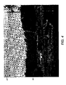
- the guide image 62 is then communicated to LCD 40 for viewing. This allows the user to frame a current image being viewed through the viewfinder with an older image that has been converted to an outline. As shown in Figure 4, the guide image 62 guides a new view of the parking lot scene. Thus, the guide image 62 acts as a guide when taking a second picture of the parking lot after an elapsed period of time, that allows the user to capture the same composition and perspective as shown in Figure 2.
- the user may not need both the same composition and the same perspective. It is obvious to anyone skilled in the art of photography that these are two separate concepts. However, the embodiments disclosed herein clearly allow the user to substantially maintain both of these qualities between images that are recorded at different times.
- edge detect filter 48 and guide image maker 50 are illustrated as two parts of the same device, a single element may accomplish both these functions or alternatively, the filter 48 and the image maker 50 may be entirely separate devices within the camera 10.
- This idea may also be applied to digital video cameras, where a still "frame” or series of frames, may be stored, such that a user could begin recording a new sequence at the same perspective as an earlier recorded shot.
Landscapes
- Engineering & Computer Science (AREA)
- Multimedia (AREA)
- Signal Processing (AREA)
- Studio Devices (AREA)
- Indication In Cameras, And Counting Of Exposures (AREA)
- Editing Of Facsimile Originals (AREA)
- Television Signal Processing For Recording (AREA)
- Cameras In General (AREA)
Abstract
Description
Claims (7)
- An apparatus, comprising:a light sensitive sensor that generates electrical charges in relation to amounts of light reflected from an external object, said sensor being adapted to record a first image;an image editor device adapted to receive a processed form of the first image and which creates a guide image; anda display operably connected to the image editing device with which to view a superposition of a second image and the guide image before recording the second image.
- The apparatus according to claim 1, wherein the image editing device includes a filter adapted to produce an outline of the object in the first image.
- A method of using a digital camera, comprising:wherein the guide image is superimposed over an initial image of the at least one second subject in preparation for recording the second image so that the second image will be recorded with at least one of substantially the same composition and substantially the same perspective as the first image.recording a first image of at least one first subject;generating a guide image from the first image;using the guide image to record a second image of at least one second subject,
- The method of claim 3, wherein the second subject and the first subject are substantially the same.
- The method of claim 3 or 4, wherein the second image is recorded at a later time than the first image.
- The method according to any one of the preceding claims, wherein generating a guide image includes producing an outline of the at least part of the first image.
- A method for using a camera, comprising:providing a light sensitive sensor;acquiring a first image from the sensor;processing the first image;sending the first image to an image editor;creating a guide image from the first image with the image editor;displaying the guide image on a display element of the camera during a user's preparation to acquire a second image from the light sensor.
Applications Claiming Priority (2)
| Application Number | Priority Date | Filing Date | Title |
|---|---|---|---|
| US632204 | 1996-04-15 | ||
| US10/632,204 US20050024517A1 (en) | 2003-07-29 | 2003-07-29 | Digital camera image template guide apparatus and method thereof |
Publications (2)
| Publication Number | Publication Date |
|---|---|
| EP1503581A2 true EP1503581A2 (en) | 2005-02-02 |
| EP1503581A3 EP1503581A3 (en) | 2006-01-25 |
Family
ID=33541538
Family Applications (1)
| Application Number | Title | Priority Date | Filing Date |
|---|---|---|---|
| EP04254107A Withdrawn EP1503581A3 (en) | 2003-07-29 | 2004-07-08 | Digital camera image |
Country Status (4)
| Country | Link |
|---|---|
| US (1) | US20050024517A1 (en) |
| EP (1) | EP1503581A3 (en) |
| JP (1) | JP2005051776A (en) |
| CN (1) | CN1578408A (en) |
Cited By (6)
| Publication number | Priority date | Publication date | Assignee | Title |
|---|---|---|---|---|
| WO2009087499A1 (en) | 2008-01-08 | 2009-07-16 | Sony Ericsson Mobile Communications Ab | Using a captured background image for taking a photograph |
| US20130201354A1 (en) * | 2012-02-03 | 2013-08-08 | Dealer Dot Com, Inc. | Image Capture System |
| US8947453B2 (en) | 2011-04-01 | 2015-02-03 | Sharp Laboratories Of America, Inc. | Methods and systems for mobile document acquisition and enhancement |
| EP2752807A4 (en) * | 2011-08-30 | 2015-02-18 | Fujitsu Ltd | IMAGING DEVICE, IMAGING MEDIUM PROGRAM, INFORMATION PROVIDING METHOD, AND INFORMATION PROVIDING PROGRAM |
| US9094617B2 (en) | 2011-04-01 | 2015-07-28 | Sharp Laboratories Of America, Inc. | Methods and systems for real-time image-capture feedback |
| US11153472B2 (en) | 2005-10-17 | 2021-10-19 | Cutting Edge Vision, LLC | Automatic upload of pictures from a camera |
Families Citing this family (31)
| Publication number | Priority date | Publication date | Assignee | Title |
|---|---|---|---|---|
| KR100548004B1 (en) * | 2004-05-03 | 2006-02-01 | 삼성테크윈 주식회사 | Control method of digital shooting device and digital shooting device using this method |
| US7782384B2 (en) * | 2004-11-05 | 2010-08-24 | Kelly Douglas J | Digital camera having system for digital image composition and related method |
| US8593518B2 (en) * | 2007-02-01 | 2013-11-26 | Pictometry International Corp. | Computer system for continuous oblique panning |
| US9262818B2 (en) | 2007-05-01 | 2016-02-16 | Pictometry International Corp. | System for detecting image abnormalities |
| KR101618759B1 (en) * | 2008-12-24 | 2016-05-09 | 삼성전자주식회사 | Apparatus and method for capturing image |
| US8331688B2 (en) | 2009-01-07 | 2012-12-11 | International Business Machines Corporation | Focus-based edge detection |
| JP2011211493A (en) * | 2010-03-30 | 2011-10-20 | Sony Corp | Imaging apparatus, display method, and program |
| JP5716130B2 (en) * | 2012-03-28 | 2015-05-13 | 富士フイルム株式会社 | Imaging apparatus and imaging support method |
| US9251396B2 (en) | 2013-01-29 | 2016-02-02 | Diamond Fortress Technologies, Inc. | Touchless fingerprinting acquisition and processing application for mobile devices |
| CN104885444A (en) * | 2013-09-09 | 2015-09-02 | 宇龙计算机通信科技(深圳)有限公司 | Image processing method and terminal |
| JP2018535568A (en) | 2015-09-02 | 2018-11-29 | サムロール エルエルシー | Camera system and method for registering images and presenting a series of aligned images |
| US10009536B2 (en) | 2016-06-12 | 2018-06-26 | Apple Inc. | Applying a simulated optical effect based on data received from multiple camera sensors |
| DK180859B1 (en) | 2017-06-04 | 2022-05-23 | Apple Inc | USER INTERFACE CAMERA EFFECTS |
| US10924660B2 (en) * | 2018-03-28 | 2021-02-16 | Candice D. Lusk | Augmented reality markers in digital photography |
| US11722764B2 (en) | 2018-05-07 | 2023-08-08 | Apple Inc. | Creative camera |
| WO2020003944A1 (en) * | 2018-06-29 | 2020-01-02 | 富士フイルム株式会社 | Imaging device, imaging method, and program |
| DK201870623A1 (en) | 2018-09-11 | 2020-04-15 | Apple Inc. | USER INTERFACES FOR SIMULATED DEPTH EFFECTS |
| US11321857B2 (en) | 2018-09-28 | 2022-05-03 | Apple Inc. | Displaying and editing images with depth information |
| US11128792B2 (en) | 2018-09-28 | 2021-09-21 | Apple Inc. | Capturing and displaying images with multiple focal planes |
| CN109257541A (en) * | 2018-11-20 | 2019-01-22 | 厦门盈趣科技股份有限公司 | Householder method of photographing and device |
| US11770601B2 (en) | 2019-05-06 | 2023-09-26 | Apple Inc. | User interfaces for capturing and managing visual media |
| US11706521B2 (en) | 2019-05-06 | 2023-07-18 | Apple Inc. | User interfaces for capturing and managing visual media |
| JP2019191589A (en) * | 2019-05-24 | 2019-10-31 | 日本電気株式会社 | Photographing system, photographing method and program |
| CN110266958B (en) * | 2019-07-12 | 2022-03-01 | 北京小米移动软件有限公司 | Shooting method, device and system |
| US11054973B1 (en) | 2020-06-01 | 2021-07-06 | Apple Inc. | User interfaces for managing media |
| US11212449B1 (en) | 2020-09-25 | 2021-12-28 | Apple Inc. | User interfaces for media capture and management |
| US11539876B2 (en) | 2021-04-30 | 2022-12-27 | Apple Inc. | User interfaces for altering visual media |
| US11778339B2 (en) | 2021-04-30 | 2023-10-03 | Apple Inc. | User interfaces for altering visual media |
| US12112024B2 (en) | 2021-06-01 | 2024-10-08 | Apple Inc. | User interfaces for managing media styles |
| US12450854B2 (en) | 2022-09-22 | 2025-10-21 | Apple Inc. | User interfaces for capturing media and manipulating virtual objects |
| US12401889B2 (en) | 2023-05-05 | 2025-08-26 | Apple Inc. | User interfaces for controlling media capture settings |
Family Cites Families (8)
| Publication number | Priority date | Publication date | Assignee | Title |
|---|---|---|---|---|
| JPH05145810A (en) * | 1991-11-20 | 1993-06-11 | Asahi Optical Co Ltd | Cameras that can be superimposed |
| US5790193A (en) * | 1995-11-22 | 1998-08-04 | Eastman Kodak Company | Accessory module for an electronic camera |
| JP3839526B2 (en) * | 1996-09-20 | 2006-11-01 | 富士写真フイルム株式会社 | Digital camera |
| US6262769B1 (en) * | 1997-07-31 | 2001-07-17 | Flashpoint Technology, Inc. | Method and system for auto rotating a graphical user interface for managing portrait and landscape images in an image capture unit |
| IL121697A0 (en) * | 1997-09-03 | 1998-02-22 | Scitex Corp Ltd | Apparatus and method for digital photography |
| US6466701B1 (en) * | 1997-09-10 | 2002-10-15 | Ricoh Company, Ltd. | System and method for displaying an image indicating a positional relation between partially overlapping images |
| US6978051B2 (en) * | 2000-03-06 | 2005-12-20 | Sony Corporation | System and method for capturing adjacent images by utilizing a panorama mode |
| JP2001255862A (en) * | 2000-03-10 | 2001-09-21 | Seiko Epson Corp | Overlay image processing device and overlay image display device |
-
2003
- 2003-07-29 US US10/632,204 patent/US20050024517A1/en not_active Abandoned
-
2004
- 2004-07-08 EP EP04254107A patent/EP1503581A3/en not_active Withdrawn
- 2004-07-26 JP JP2004216824A patent/JP2005051776A/en not_active Withdrawn
- 2004-07-29 CN CNA2004100590170A patent/CN1578408A/en active Pending
Cited By (11)
| Publication number | Priority date | Publication date | Assignee | Title |
|---|---|---|---|---|
| US11153472B2 (en) | 2005-10-17 | 2021-10-19 | Cutting Edge Vision, LLC | Automatic upload of pictures from a camera |
| US11818458B2 (en) | 2005-10-17 | 2023-11-14 | Cutting Edge Vision, LLC | Camera touchpad |
| WO2009087499A1 (en) | 2008-01-08 | 2009-07-16 | Sony Ericsson Mobile Communications Ab | Using a captured background image for taking a photograph |
| US7991285B2 (en) | 2008-01-08 | 2011-08-02 | Sony Ericsson Mobile Communications Ab | Using a captured background image for taking a photograph |
| US8947453B2 (en) | 2011-04-01 | 2015-02-03 | Sharp Laboratories Of America, Inc. | Methods and systems for mobile document acquisition and enhancement |
| US9094617B2 (en) | 2011-04-01 | 2015-07-28 | Sharp Laboratories Of America, Inc. | Methods and systems for real-time image-capture feedback |
| EP2752807A4 (en) * | 2011-08-30 | 2015-02-18 | Fujitsu Ltd | IMAGING DEVICE, IMAGING MEDIUM PROGRAM, INFORMATION PROVIDING METHOD, AND INFORMATION PROVIDING PROGRAM |
| US20130201354A1 (en) * | 2012-02-03 | 2013-08-08 | Dealer Dot Com, Inc. | Image Capture System |
| WO2013116487A3 (en) * | 2012-02-03 | 2013-10-10 | Dealer Dot Com, Inc. | Image capture system |
| AU2013215098B2 (en) * | 2012-02-03 | 2017-02-02 | Dealer Dot Com, Inc. | Image capture system |
| US9641760B2 (en) * | 2012-02-03 | 2017-05-02 | Dealer Dot Com, Inc. | Image capture system |
Also Published As
| Publication number | Publication date |
|---|---|
| EP1503581A3 (en) | 2006-01-25 |
| CN1578408A (en) | 2005-02-09 |
| JP2005051776A (en) | 2005-02-24 |
| US20050024517A1 (en) | 2005-02-03 |
Similar Documents
| Publication | Publication Date | Title |
|---|---|---|
| US20050024517A1 (en) | Digital camera image template guide apparatus and method thereof | |
| US6714249B2 (en) | Producing panoramic digital images by digital camera systems | |
| US7839429B2 (en) | In-camera panorama stitching method and apparatus | |
| US10469746B2 (en) | Camera and camera control method | |
| JP4957759B2 (en) | Imaging apparatus and imaging method | |
| WO2000076206A1 (en) | Electronic still camera | |
| US20060092297A1 (en) | Method and apparatus for removing hot pixels in a digital camera | |
| US7471328B2 (en) | Apparatus and method for rotating image in digital camera | |
| KR101058025B1 (en) | Image display device and method using dual thumbnail mode | |
| JP4333394B2 (en) | Camera device, imaging method and program thereof | |
| US20050264668A1 (en) | Electronic apparatus with image capturing function and image display method | |
| US20060197848A1 (en) | Image recording apparatus and method | |
| JP2010286752A (en) | Imaging device and imaging method | |
| JP4457929B2 (en) | Imaging device | |
| JP2004248171A (en) | Moving image recorder, moving image reproduction device, and moving image recording and reproducing device | |
| JP2005260879A (en) | Digital camera | |
| JP4828486B2 (en) | Digital camera, photographing method and photographing program | |
| JP5021370B2 (en) | Imaging apparatus, display method, and program | |
| JP5522214B2 (en) | Camera device and through image display method | |
| JP2002152586A (en) | Electronic camera | |
| JP5109996B2 (en) | Camera device, through image display method and program thereof | |
| JP2009141978A (en) | Camera device, through image display method and program thereof | |
| JP3913046B2 (en) | Imaging device | |
| JP2010087955A (en) | Display controller, method for controlling display device, and program | |
| JP4868001B2 (en) | Camera device, through image display method and program thereof |
Legal Events
| Date | Code | Title | Description |
|---|---|---|---|
| PUAI | Public reference made under article 153(3) epc to a published international application that has entered the european phase |
Free format text: ORIGINAL CODE: 0009012 |
|
| AK | Designated contracting states |
Kind code of ref document: A2 Designated state(s): AT BE BG CH CY CZ DE DK EE ES FI FR GB GR HU IE IT LI LU MC NL PL PT RO SE SI SK TR |
|
| AX | Request for extension of the european patent |
Extension state: AL HR LT LV MK |
|
| PUAL | Search report despatched |
Free format text: ORIGINAL CODE: 0009013 |
|
| AK | Designated contracting states |
Kind code of ref document: A3 Designated state(s): AT BE BG CH CY CZ DE DK EE ES FI FR GB GR HU IE IT LI LU MC NL PL PT RO SE SI SK TR |
|
| AX | Request for extension of the european patent |
Extension state: AL HR LT LV MK |
|
| AKX | Designation fees paid | ||
| REG | Reference to a national code |
Ref country code: DE Ref legal event code: 8566 |
|
| STAA | Information on the status of an ep patent application or granted ep patent |
Free format text: STATUS: THE APPLICATION IS DEEMED TO BE WITHDRAWN |
|
| 18D | Application deemed to be withdrawn |
Effective date: 20060726 |