EP1503505A2 - Noise determination and DSL Modem with noise determination - Google Patents
Noise determination and DSL Modem with noise determination Download PDFInfo
- Publication number
- EP1503505A2 EP1503505A2 EP04103579A EP04103579A EP1503505A2 EP 1503505 A2 EP1503505 A2 EP 1503505A2 EP 04103579 A EP04103579 A EP 04103579A EP 04103579 A EP04103579 A EP 04103579A EP 1503505 A2 EP1503505 A2 EP 1503505A2
- Authority
- EP
- European Patent Office
- Prior art keywords
- noise
- crosstalk
- recited
- dsl
- noise source
- Prior art date
- Legal status (The legal status is an assumption and is not a legal conclusion. Google has not performed a legal analysis and makes no representation as to the accuracy of the status listed.)
- Withdrawn
Links
- 238000004891 communication Methods 0.000 claims abstract description 29
- 238000000034 method Methods 0.000 claims abstract description 21
- 230000005540 biological transmission Effects 0.000 claims description 5
- 230000003595 spectral effect Effects 0.000 claims description 5
- 239000000654 additive Substances 0.000 claims description 3
- 230000000996 additive effect Effects 0.000 claims description 3
- 230000008569 process Effects 0.000 claims description 3
- 239000011159 matrix material Substances 0.000 description 13
- 238000011144 upstream manufacturing Methods 0.000 description 6
- 238000010586 diagram Methods 0.000 description 4
- RYGMFSIKBFXOCR-UHFFFAOYSA-N Copper Chemical compound [Cu] RYGMFSIKBFXOCR-UHFFFAOYSA-N 0.000 description 3
- 229910052802 copper Inorganic materials 0.000 description 3
- 239000010949 copper Substances 0.000 description 3
- 238000011022 operating instruction Methods 0.000 description 3
- 238000004088 simulation Methods 0.000 description 3
- 239000013256 coordination polymer Substances 0.000 description 2
- 239000000203 mixture Substances 0.000 description 2
- 230000004044 response Effects 0.000 description 2
- 238000007493 shaping process Methods 0.000 description 2
- 238000012549 training Methods 0.000 description 2
- 238000000342 Monte Carlo simulation Methods 0.000 description 1
- 230000004075 alteration Effects 0.000 description 1
- 238000004364 calculation method Methods 0.000 description 1
- 239000003990 capacitor Substances 0.000 description 1
- 230000015556 catabolic process Effects 0.000 description 1
- 230000008859 change Effects 0.000 description 1
- 238000010276 construction Methods 0.000 description 1
- 230000008878 coupling Effects 0.000 description 1
- 238000010168 coupling process Methods 0.000 description 1
- 238000005859 coupling reaction Methods 0.000 description 1
- 125000004122 cyclic group Chemical group 0.000 description 1
- 238000000354 decomposition reaction Methods 0.000 description 1
- 230000007812 deficiency Effects 0.000 description 1
- 238000006731 degradation reaction Methods 0.000 description 1
- 230000001419 dependent effect Effects 0.000 description 1
- 238000001514 detection method Methods 0.000 description 1
- 230000000694 effects Effects 0.000 description 1
- 238000001914 filtration Methods 0.000 description 1
- 230000006872 improvement Effects 0.000 description 1
- 238000005259 measurement Methods 0.000 description 1
- 238000012986 modification Methods 0.000 description 1
- 230000004048 modification Effects 0.000 description 1
- 238000001228 spectrum Methods 0.000 description 1
- 230000007480 spreading Effects 0.000 description 1
- 238000006467 substitution reaction Methods 0.000 description 1
- 238000012360 testing method Methods 0.000 description 1
Images




Classifications
-
- H—ELECTRICITY
- H04—ELECTRIC COMMUNICATION TECHNIQUE
- H04L—TRANSMISSION OF DIGITAL INFORMATION, e.g. TELEGRAPHIC COMMUNICATION
- H04L1/00—Arrangements for detecting or preventing errors in the information received
- H04L1/20—Arrangements for detecting or preventing errors in the information received using signal quality detector
-
- H—ELECTRICITY
- H04—ELECTRIC COMMUNICATION TECHNIQUE
- H04B—TRANSMISSION
- H04B3/00—Line transmission systems
- H04B3/02—Details
- H04B3/46—Monitoring; Testing
- H04B3/487—Testing crosstalk effects
Definitions
- the present invention is directed, in general, to identifying noise within a communications system and, more specifically, to a noise determiner, a digital subscriber line (DSL) modem including the noise determiner and a method of determining noise.
- DSL digital subscriber line
- Performance of a communications system is affected by noise associated with an operating environment of the system. Understanding the noise typically assists communication through the system whether the system is wireless or wired.
- a digital subscriber line (DSL) system is an example of a wired communications system that communicates over copper telephone wires, a part of what is commonly referred to as the Plain Old Telephone System (POTS).
- POTS Plain Old Telephone System
- An Asymmetric DSL (ADSL) system is a type of DSL system that receives data at a higher rate (known as the downstream rate) than when transmitting data (known as the upstream rate).
- a remote terminal or modem receives data from and transmits data to an ADSL modem connected to a Digital Subscriber Line Access Multiplier (DSLAM) in a central office over a channel that includes the copper telephone wires.
- DSLAM Digital Subscriber Line Access Multiplier
- identifying the noise source may allow the remote or central office modem to more easily determine deployment problems. Identifying noise sources, however, often increases the cost of a modem by requiring additional computations. A tradeoff, therefore, may exist between cost and performance.
- the present invention provides a noise determiner for use with a communications system, a method of determining noise in a communications system and a digital subscriber line (DSL) modem.
- the noise determiner includes (1) a crosstalk identifier configured to detect directly a noise source in a frequency domain from observed noise associated with the communications system and (2) a crosstalk estimator coupled to the crosstalk identifier and configured to provide a corresponding level of the noise source.
- the present invention provides a method of determining noise in a communications system including (1) directly detecting a noise source in a frequency domain from observed noise associated with the communications system and (2) providing a corresponding level of the noise source.
- the present invention provides a single pass method of doing a least-squares fit of noise sources using a power spectral density (PSD) of an observed noise.
- the noise sources have a multiplicative form discussed herein.
- the present invention may consider radio frequency interference (RFI) and unknown disturbers in the observed noise.
- RFID radio frequency interference
- the present invention therefore, may identify noise sources having the multiplicative form in the presence of unknown disturbers.
- the single pass method allows the present invention to detect directly, or non-iteratively, the noise sources and provide a corresponding level associated with each of the noise sources.
- the corresponding level may be an estimated energy percentage of a total energy associated with the observed noise.
- the present invention provides a DSL modem including (1) a front end coupled to a DSL channel, (2) a transmitter coupled to the front end that processes a digital signal for analog transmission over the channel, (3) a receiver coupled to the front end that converts an analog signal received over the channel to a digital signal and (4) a noise determiner.
- the noise determiner includes (4a) a crosstalk identifier that detects directly in a frequency domain a noise source from observed noise associated with the channel and (4b) a crosstalk estimator coupled to the crosstalk identifier that provides a corresponding level of the noise source.
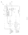
- FIGURE 1 illustrated is a block diagram of an embodiment of an Asymmetric Digital Subscriber Line (ADSL) modem, generally designated 100, constructed in accordance with the principles of the present invention.
- the ADSL modem 100 includes a front end 110, a transmitter 120, a receiver 130, and a noise determiner 140.
- the noise determiner 140 includes a crosstalk identifier 144 and a crosstalk estimator 148.
- the ADSL modem 100 may include components typically employed within a conventional DSL modem.
- the ADSL modem 100 may be a remote terminal that communicates with a Digital Subscriber Line Access Multiplier (DSLAM) in a central office of an ADSL system via a central office ADSL modem.
- the ADSL modem 100 may be another type of modem, such as, for example, a digital subscriber line (DSL) modem.
- the ADSL modem 100 could be a High bit-rate DSL (HDSL), a Single line DSL (SDSL) or a Very high bit-rate DSL (VDSL) modem.
- HDSL High bit-rate DSL
- SDSL Single line DSL
- VDSL Very high bit-rate DSL
- the ADSL modem 100 may include additional components than those illustrated and discussed.
- the front end 110 coupled to the transmitter 120 and the receiver 130, provides a connection for the ADSL modem 100 to a channel.
- the front end 110 may include a transformer, coupling capacitors and a hybrid.
- the channel may be a copper telephone line coupled to the central office ADSL modem. Additionally, the channel may include transmit filters at the ADSL modem 100 and receive filters at the central office ADSL modem.
- the transmitter 120 may be configured to send a signal, an upstream signal, via the channel to the DSLAM.
- the transmitter 120 may receive the signal in a digital format from a computer system coupled to the ADSL modem 100.
- the transmitter 120 may process the digital signal for transmission including converting the upstream signal from a time domain to a frequency domain, adding a cyclic prefix and modulating the upstream signal.
- the transmitter 120 may include a digital-to-analog converter (DAC) and filters, digital and analog, for shaping and attenuating the upstream signal.
- the transmitter 120 may include a line driver that adjusts transmit power of the upstream signal to adhere to a given power spectral density (PSD) mask.
- PSD power spectral density
- the transmitter 120 may be embodied as a sequence of operating instruction, dedicated hardware or a combination thereof. Some functionality of the transmitter 120 may be employed on a digital signal processor (DSP).
- DSP digital signal processor
- the receiver 130 may be configured to receive a signal, a downstream signal, in an analog format from the DSLAM via the channel. Essentially, the receiver 130 may operate in reverse of the transmitter 120. For example, the receiver 130 may convert the downstream signal from an analog format to a digital format for the computer system by employing an analog-to-digital converter (ADC). Additionally, the receiver 130 may include analog and digital filters for reducing noise and shaping the downstream signal.
- ADC analog-to-digital converter
- the receiver 130 may be embodied as a sequence of operating instruction, dedicated hardware or a combination thereof. Some functionality of the receiver 130 may be employed on a DSP.
- the ADSL modem 100 also includes the noise determiner 140.
- the noise determiner 140 identifies different noise sources that are present in the ADSL system and estimates corresponding levels or parameters for the noise sources.
- the noise determiner 140 may be a part of the receiver 130.
- the noise determiner 140 may be a sequence of operating instructions employed on a DSP.
- the noise determiner 140 may be integrated with a datapump of the ADSL modem 100.
- the noise determiner 140 may operate before the ADSL modem 100 trains or may operate during an appropriate period of a training sequence.
- the noise determiner 140 may be implemented without real time computational requirements.
- the noise determiner 140 includes the crosstalk identifier 144 and the crosstalk estimator 148.
- the crosstalk identifier 144 detects directly in a frequency domain a noise source from observed noise associated with the channel.
- PSD power spectral density
- the crosstalk identifier 144 may consider radio frequency interference (RFI) when identifying noise sources. Additionally, the crosstalk identifier 144 may operate in an environment having unknown disturbers. Preferably, the unknown disturbers in the environment are small compared to noise sources that may be identified. An unknown disturber may be a source of noise that has a PSD unknown to the noise determiner 140 whereas the noise determiner 140 may know the PSD of known noise sources.
- RFID radio frequency interference
- noise sources that may typically affect the ADSL system may include, but not limited to, Additive White Gaussian Noise (AWGN), Digital Subscriber Line (DSL) Near-End Crosstalk (NEXT), High bit-rate DSL (HDSL) NEXT, T1 NEXT, and European Technical Standards Institute (ETSI) defined noises.
- AWGN Additive White Gaussian Noise
- DSL Digital Subscriber Line
- NEXT Near-End Crosstalk
- HDSL High bit-rate DSL
- ETSI European Technical Standards Institute
- other communications systems may include different or additional known noise sources.
- the noise sources may be associated with modeling system such as an American noise model, an old ETSI noise model, and a new ETSI noise model.
- the crosstalk identifier 144 may advantageously identify a mixture of noise sources that have the multiplicative form expressed as EQUATION 1.
- the crosstalk estimator 148 coupled to the crosstalk identifier 144, provides a corresponding level of the noise source.
- the crosstalk estimator 148 may determine the corresponding level of the noise source by employing the scaling function g. Operation of a noise determiner including a crosstalk identifier and a crosstalk estimator will be discussed in more detail with respect to FIGURE 2.
- FIGURE 2 illustrated is a block diagram of an embodiment of a noise determiner, generally designated 200, constructed according to the principles of the present invention.
- the noise determiner 200 includes a crosstalk identifier 220 and a crosstalk estimator 240.
- the noise determiner 200 may be configured to identify different noise sources present in a communications system and estimate corresponding levels and parameters for the noise sources.
- the communications system is an ADSL system and the noise determiner 200 may be employed within a receiver of an ADSL modem.
- the communications system may be a DSL system or another type of DSL system such as an HDSL, an SDSL or a VDSL system.
- the noise determiner 200 may be trained off-line to estimate a noise floor associated with a CODEC of the ADSL modem and the noise sources that the ADSL modem may be expected to encounter.
- the noise determiner 200 may estimate the PSDs and determine the corresponding levels of the noise sources by "listening" to a channel before training begins (i.e. when a central office modem is quiet).
- the noise determiner 200 may send the levels and report the channel conditions to the receiver for possible modifications to adapt the receiver to conditions of the channel before establishing a connection.
- the crosstalk identifier 220 may be configured to detect directly a noise source in a frequency domain from observed noise associated with the communications system.
- a PSD of the observed noise may result from a variety of noise sources.
- Some common noise sources that may affect performance in an ADSL system may include AWGN, DSL NEXT, HDSL NEXT, T1 NEXT, and ETSI defined noise.
- Basis functions ( P B ( f )) and scaling functions (g(k)) which may be associated with these type of noise sources in an ADSL system are represented below in sections a-g.
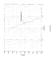
- FIGURE 5 includes an example of ETSI PSDs for NEXT and FEXT noises.
- the NEXT noises may be calculated with a straight loop of length 3kft and the FEXT noises may be calculated with a straight loop of length 10kft.
- the NEXT and FEXT different noise sources may be designated as NEXTA, NEXTB, NEXTC, NEXTD, FEXTA, FEXTB, FEXTC and FEXTD.
- the component noise sources may be the noise sources listed above in sections a-g.
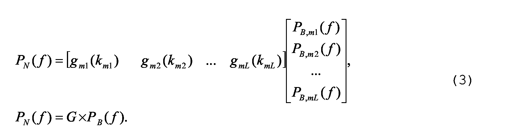
- the crosstalk identifier 220 may employ EQUATION 4 to determine the scaling vector G and send the scaling vector G to the crosstalk estimator 240.
- the crosstalk estimator 240 coupled to the crosstalk identifier 220, may be configured to provide a corresponding level associated with each component noise source.
- the crosstalk estimator 240 may employ the scaling vector G to determine the corresponding level of the noise source.
- an ADSL system may have an observed noise that includes component noise sources with known PSDs.
- the observed noise source may include AWGN noise, HDSL-NEXT, DSL-NEXT, T1-NEXT, Noise A, Noise B, NEXT B and FEXT A.
- AWGN noise AWGN noise
- HDSL-NEXT High Speed Downlink
- DSL-NEXT DSL-NEXT
- T1-NEXT Noise A
- Noise B Noise B
- NEXT B NEXT B
- FEXT A FEXT
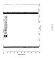
- the crosstalk identifier 220 may employ the known PSDs of the component noise sources of FIGURE 7 and the PSD of the observed noise, P N ( f ), to determine a scaling vector G.
- the crosstalk estimator 240 may then employ the scaling vector G to calculate levels of the component noise sources. The resulting values are given in TABLE 1 of FIGURE 6.
- the crosstalk estimator may also estimate parameters associated with the component noise sources in determining the corresponding levels associated therewith.
- the parameters for example, may include an average PSD, a number of disturbers, power, existence or loop length.
- the noise determiner 200 may also operate in an environment of noise sources having unknown PSDs.
- the unknown PSDs may result from mismatches of noise sources to noise models or may be a source of unknown interference.
- an observed noise may be modeled according to EQUATION 5, where N(f) denotes a PSD of an unknown interference.
- MSE minimized square error
- the noise determiner 200 may improve robustness by placing the noise source in a proper noise model.
- the component noise sources may be separated, for example, into three modeling systems: an American noise model, an old ETSI noise model and a new ETSI noise model.
- each modeling system exclusively describes component noise sources associated with its own modeling system such that component noise sources from different modeling systems do not coexist together.
- the noise determiner 200 may further increase robustness for new ETSI noise models by selectively classifying and including ETSI noise sources.
- the crosstalk identifier 220 may realize that NEXT A and NEXT B have similar PSD shapes while FEXT A, FEXT B and FEXT C have similar PSD shapes as illustrated in FIGURE 5. Accordingly, the crosstalk identifier 220 may classify NEXT A and NEXT B as one type of noise source and include NEXT B in the shape matrix P B . Furthermore, the crosstalk identifier 220 may classify FEXT A, FEXT B and FEXT C as one type of noise source and include FEXT B in the shape matrix P B .
- noise sources A, B, C, D may represent different noise scenarios and may not coexist with each other. Since a level of NEXT A is higher than a level of NEXT B, scaling results may be used to distinguish between NEXT A and NEXT B.
- the noise determiner 200 may also increase robustness by ignoring a FEXT noise source.
- a PSD of the FEXT noise source may be highly dependent on a channel response. If a FEXT noise source is considered in the base PSD matrix, the crosstalk identifier 220 may be required to perform an online calculation to compute a pseudo inverse of the base PSD matrix. On the other hand, a PSD of a NEXT noise source has limited dependency on a channel response. Accordingly, the crosstalk identifier 220 may consider PSDs of NEXT noise sources and ignore PSDs of FEXT noise sources in the base PSD matrix to allow pre-computing of the inverse matrix to simplify real-time computational complexity.
- the FEXT noise source becomes unknown interference, for medium-long loops, the FEXT noise source typically has limited contribution to an overall PSD of the observed noise. Since PSDs for NEXT of the new ETSI noise model hardly change for loop lengths greater than 100ft, the crosstalk identifier 220 may assume basis PSDs for this noise source to be constant and pre-computed.
- the noise determiner 200 may consider RFI.
- RFI identification may be difficult because a tone of the RFI may occur at a center of a Fast Fourier Transform (FFT) bin when, for example, the FFT is large.
- the RFI tone may manifest itself by a spike in the PSD of the observed noise if the RFI is stronger than a level of other noise sources.
- FFT Fast Fourier Transform
- the RFI may "spread" (FFT spreading) and smear the PSD of the observed noise causing difficulty in identifying noise sources.
- the crosstalk identifier 220 may consider the RFI as another noise source with a known PSD basis. Alternatively, the crosstalk identifier 220 may detect and remove the RFI. The crosstalk identifier 220 may detect and remove the RFI from the observed noise PSD by smoothening the observed noise PSD. To smoothen, the crosstalk identifier 220 may locate frequencies at which peak amplitudes exist in the observed noise PSD to determine frequencies at which RFI tones occur. Based on the peak amplitudes, the crosstalk identifier 220 may estimate strength of the RFI tones which may include analyzing PSD of bins surrounding the peak amplitudes to fine-tune the strength estimates.
- the crosstalk identifier 220 may subtract the peak amplitudes from peak positions or average RFI peak points to remove the RFI peaks and provide a smoother observed noise PSD that may be employed as P N (f) . Although the RFI may not be completely removed, the noise determiner 200 may achieve good performance due to improved robustness.
- the crosstalk identifier 220 may smooth the RFI employing a different procedure.
- the crosstalk identifier 220 locates frequencies at which peaks exist in the overall observed noise PSD to provide the the frequencies of the RFI tones. The strength of the RFI tones may be estimated based on peak amplitudes.
- the crosstalk identifier 220 may analyze a PSD at bins surrounding the peak to fine-tune frequency/amplitude estimates.
- the crosstalk identifier 220 may obtain a total RFI PSD by taking a FFT (of the same size as used in the computation of the overall observed noise PSD) of a summation of the RFI tones.
- the RFI tones may have the frequency and power as determined previously.
- the crosstalk identifier 220 may subtract the total RFI PSD from the overall observed noise PSD and, with some additional filtering, effectively remove effects of RFI and provide a smooth PSD that may be used as P N ( f ).
- the crosstalk identifier 200 may need to identify a noise model as well as noise sources within the noise model.
- the crosstalk identifier 220 may detect and smoothen the RFI if present.
- the noise determiner 200 may identify various noise sources based on an overall observed noise PSD that may be measured by the noise determiner 200 or, in some embodiments, a receiver of an ADSL modem. Additionally, robustness of the noise determiner 200 may allow the use of a simple RFI smoothening technique without significant performance degradation. Although the noise determiner 200 models the observed noise as a summation of individual noise sources, the noise determiner 200 may also work as well with other combining methods like the FSAN method disclosed in Draft Proposed American National Standard Spectrum Management for Loop Transmission Systems, Issue 2, T1E1.4/2001-002, May 2001, which is hereby incorporated by reference in its entirety.
- EQUATION 2 may be represented by EQUATION 13, where p m (f) is a PSD of an individual noise source.
- EQUATION 4 may be adapted to EQUATION 14.
- G [( P N ( f )) 1/0.6 ⁇ (( P B ( f )) 1/0.6 ) -1 ] 0.6
- the noise determiner 200 may be adapted to provide corresponding levels of individual noise sources for different models.
- the ADSL communications system includes an ADSL Customer Premise Equipment (CPE) modem operating in a noisy environment.
- the noise is generated randomly following one of three noise models, i.e ., American noise model, new ESTI noise model and old ETSI noise model. A level of the noise or a number of disturbers is generated randomly.
- RFI noise and unknown interference may be also included for testing purposes.
- EQUATION 15 is a normalized energy difference between an actual value and an estimated value and E (i), is a total actual (estimated) energy of an i th noise source.
- EQUATION 15 is a normalized energy difference between an actual value and an estimated value
- E (i) is a total actual (estimated) energy of an i th noise source.
- the energy difference in AWGN and RFI noise may be ignored with focus placed on crosstalk noise source identification.
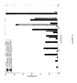
- FIGURE 8 represents a histogram of the accuracy results from simulations where unknown interference was not introduced.
- FIGUREs 7 and 8 represent determining the noise sources in presence of unknown interference and RFI.
- the unknown interference may be generated randomly with a maximum PSD level at 10dB lower than an observed received noise PSD and the RFI noise is generated randomly with a maximum PSD level 9dB higher than the observed received noise PSD.
- the channel may be generated longer than 7kft to limit the FEXT noise level.
- FIGUREs 8-10 illustrate that performance may be degraded slightly in the presence of unknown interference and RFI and that better results may be obtained from an American noise model and an old ETSI noise model.
Landscapes
- Engineering & Computer Science (AREA)
- Computer Networks & Wireless Communication (AREA)
- Signal Processing (AREA)
- Quality & Reliability (AREA)
- Cable Transmission Systems, Equalization Of Radio And Reduction Of Echo (AREA)
- Digital Transmission Methods That Use Modulated Carrier Waves (AREA)
- Telephonic Communication Services (AREA)
Abstract
Description
P B , NoiseB (f) as illustrated in FIGURE 4. The overall wide-band noise power over the



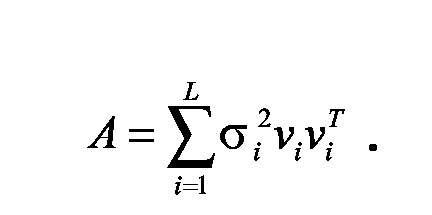
P -1 / B(f) is a pseudo-inverse of PB (f).








Claims (15)
- A noise determiner for use with a communications system, comprising:a crosstalk identifier configured to detect directly a noise source in a frequency domain from observed noise associated with said communications system; anda crosstalk estimator coupled to said crosstalk identifier and configured to provide a corresponding level of said noise source.
- A digital subscriber line (DSL) modem, comprising:a front end coupled to a DSL channel;a transmitter coupled to said front end that processes a digital signal for analog transmission over said channel; anda receiver coupled to said front end that converts an analog signal received over said channel to a digital signal; anda noise determiner as recited in Claim 1, including:the crosstalk identifier configured to detect directly in a frequency domain a noise source from observed noise associated with said channel; andthe crosstalk estimator coupled to said crosstalk identifier to provide a corresponding level of said noise source.
- The apparatus as recited in either Claim 1 or Claim 2, wherein said crosstalk identifier considers radio frequency interference.
- The apparatus as recited in any of Claims 1 - 3, wherein said crosstalk identifier considers unknown disturbers.
- The apparatus as recited in any of Claims 1 - 4, wherein said crosstalk identifier places said noise source into a modeling system selected from the group consisting of:an American noise model,an old European Technical Standards Institute (ETSI) noise model, anda new ETSI noise model.
- The apparatus as recited in any of Claims 1 - 5, wherein said noise source has a power spectral density of a form PN (f) = g(k)PB (f).
- The apparatus as recited in any of Claims 1 - 6, wherein said noise source is a noise selected from the group consisting of:Additive White Gaussian Noise,Digital Subscriber Line (DSL) Near-End Crosstalk (NEXT),High Bit-Rate DSL (HDSL) NEXT,T1 NEXT, andEuropean Technical Standards Institute (ETSI) defined noise.
- The apparatus as recited in any of Claims 1 - 7, wherein said communications system or modem is an Asymmetric DSL modem system or modem.
- A method of determining noise in a communications system, comprising:directly detecting a noise source in a frequency domain from observed noise associated with said communications system; andproviding a corresponding level of said noise source.
- The method as recited in Claim 9, wherein said detecting includes considering radio frequency interference.
- The method as recited in either Claim 9 or Claim 10, wherein said detecting includes considering unknown disturbers.
- The method as recited in any of Claims 9 - 11, wherein said detecting includes placing said noise source into a modeling system selected from the group consisting of:an American noise model,an old European Technical Standards Institute (ETSI) noise model, anda new ETSI noise model.
- The method as recited in any of Claims 9 - 12, wherein said noise source has a power spectral density of a form PN (f) = g(k)PB (f).
- The method as recited in any of Claims 9 - 13, further including selecting said noise source from the group consisting of:Additive White Gaussian Noise,Digital Subscriber Line (DSL) Near-End Crosstalk (NEXT),High Bit-Rate DSL (HDSL) NEXT,T1 NEXT, andEuropean Technical Standards Institute (ETSI) defined noise.
- The method as recited in any of Claims 9 - 14, wherein said communications system is a digital subscriber line (DSL) system.
Applications Claiming Priority (2)
| Application Number | Priority Date | Filing Date | Title |
|---|---|---|---|
| US628160 | 2003-07-28 | ||
| US10/628,160 US20050026572A1 (en) | 2003-07-28 | 2003-07-28 | Noise determiner, a DSL modem including a noise determiner and a method of determining noise in a communications system |
Publications (2)
| Publication Number | Publication Date |
|---|---|
| EP1503505A2 true EP1503505A2 (en) | 2005-02-02 |
| EP1503505A3 EP1503505A3 (en) | 2011-12-07 |
Family
ID=33541453
Family Applications (1)
| Application Number | Title | Priority Date | Filing Date |
|---|---|---|---|
| EP04103579A Withdrawn EP1503505A3 (en) | 2003-07-28 | 2004-07-26 | Noise determination and DSL Modem with noise determination |
Country Status (2)
| Country | Link |
|---|---|
| US (1) | US20050026572A1 (en) |
| EP (1) | EP1503505A3 (en) |
Cited By (1)
| Publication number | Priority date | Publication date | Assignee | Title |
|---|---|---|---|---|
| CN104335519A (en) * | 2012-05-07 | 2015-02-04 | 适应性频谱和信号校正股份有限公司 | Apparatus, system and method for impulse noise detection and mitigation |
Families Citing this family (10)
| Publication number | Priority date | Publication date | Assignee | Title |
|---|---|---|---|---|
| US6885746B2 (en) * | 2001-07-31 | 2005-04-26 | Telecordia Technologies, Inc. | Crosstalk identification for spectrum management in broadband telecommunications systems |
| US7302379B2 (en) * | 2003-12-07 | 2007-11-27 | Adaptive Spectrum And Signal Alignment, Inc. | DSL system estimation and parameter recommendation |
| US7809116B2 (en) * | 2003-12-07 | 2010-10-05 | Adaptive Spectrum And Signal Alignment, Inc. | DSL system estimation including known DSL line scanning and bad splice detection capability |
| ATE460012T1 (en) * | 2004-12-20 | 2010-03-15 | Alcatel Lucent | METHOD AND APPARATUS FOR DETERMINING TRANSMITTER PSD AT A REMOTE LOCATION |
| CN101233721B (en) * | 2005-07-10 | 2014-07-16 | 适应性频谱和信号校正股份有限公司 | Digital Subscriber Line DSL System Estimation |
| US8023825B2 (en) * | 2006-04-04 | 2011-09-20 | Cisco Technology, Inc. | Optical switching architectures for nodes in WDM mesh and ring networks |
| US8351598B2 (en) * | 2007-04-25 | 2013-01-08 | Ikanos Communications, Inc. | Crosstalk recognition in presence of radio frequency interference |
| US8730785B2 (en) * | 2009-03-11 | 2014-05-20 | At&T Intellectual Property I, L.P. | Method and apparatus for reducing noise in a communication system |
| US8600312B2 (en) * | 2010-01-25 | 2013-12-03 | Qualcomm Incorporated | Method and apparatus for spectral sensing |
| US9148199B2 (en) * | 2013-04-01 | 2015-09-29 | Fluke Corporation | Prequalification of vectoring before implementation |
Family Cites Families (3)
| Publication number | Priority date | Publication date | Assignee | Title |
|---|---|---|---|---|
| EP2267914A3 (en) * | 2000-01-07 | 2012-09-26 | Aware, Inc. | Systems and methods for loop length and bridged tap length determination of a transmission line |
| US6567465B2 (en) * | 2001-05-21 | 2003-05-20 | Pc Tel Inc. | DSL modem utilizing low density parity check codes |
| CA2454239A1 (en) * | 2001-07-31 | 2003-02-13 | Telcordia Technologies, Inc. | Improved crosstalk identification for spectrum management in broadband telecommunications systems |
-
2003
- 2003-07-28 US US10/628,160 patent/US20050026572A1/en not_active Abandoned
-
2004
- 2004-07-26 EP EP04103579A patent/EP1503505A3/en not_active Withdrawn
Cited By (1)
| Publication number | Priority date | Publication date | Assignee | Title |
|---|---|---|---|---|
| CN104335519A (en) * | 2012-05-07 | 2015-02-04 | 适应性频谱和信号校正股份有限公司 | Apparatus, system and method for impulse noise detection and mitigation |
Also Published As
| Publication number | Publication date |
|---|---|
| US20050026572A1 (en) | 2005-02-03 |
| EP1503505A3 (en) | 2011-12-07 |
Similar Documents
| Publication | Publication Date | Title |
|---|---|---|
| US8687770B2 (en) | Systems and methods for performing line imbalance measurement and mitigation based on a common mode sensor | |
| JP4694093B2 (en) | System and method for characterizing transmission lines using broadband signals in a multi-carrier DSL environment | |
| Prasad et al. | In-band full duplex broadband power line communications | |
| US6999583B2 (en) | Crosstalk identification for spectrum management in broadband telecommunications systems | |
| US7027589B2 (en) | Single-ended loop test circuitry in a central office DSL modem | |
| CN101908909B (en) | Far end crosstalk channel estimation method and device | |
| US20050026572A1 (en) | Noise determiner, a DSL modem including a noise determiner and a method of determining noise in a communications system | |
| US9246614B2 (en) | Methods and devices for transmission line analysis | |
| WO2007031025A1 (en) | Method, apparatus and system for crosstalk testing of multi-user communication line | |
| CN101459498B (en) | Detection method, apparatus and system for dispenser | |
| JP4498737B2 (en) | Advanced crosstalk identification for spectrum management in broadband communication systems | |
| WO2002058315A1 (en) | Crosstalk identification for spectrum management in broadband telecommunications systems | |
| Valenti et al. | Analysis of wideband noise measurements and implications for signal processing in ADSL systems | |
| Magesacher et al. | Exploiting the common-mode signal in xDSL | |
| TWI799235B (en) | System and method to optimize the digital subscriber line performance by negotiating the transmitter power back off | |
| CN1855917B (en) | Realization method of automatic selection of operation mode in xDSL network | |
| CN1965498B (en) | Method and apparatus for estimating operating characteristics of a multiline, vectored DSL system | |
| Ali et al. | An evaluation of frequency domain PLC interference cancellation for DSL systems | |
| Wan Abdullah et al. | Measurement and verification of the impact of electromagnetic interference from household appliances on digital subscriber loop systems | |
| Abidin et al. | G. fast channel modelling based on copper cable characteristics | |
| Abidin et al. | G. fast achievable bit rate performance based on FEXT stochastic and 99% worst case model | |
| Lindqvist et al. | Impact of crosstalk channel estimation on the DSM performance for DSL networks | |
| Aung et al. | Detection of unknown multitone interference using the AR method in slow FH/BFSK systems over Rayleigh fading channels | |
| Bharathi et al. | A Combined correlation TDR and FDR procedure for single ended loop topology estimation in DSL | |
| Linde | Comparison of theoretical models with practice for ADSL |
Legal Events
| Date | Code | Title | Description |
|---|---|---|---|
| PUAI | Public reference made under article 153(3) epc to a published international application that has entered the european phase |
Free format text: ORIGINAL CODE: 0009012 |
|
| AK | Designated contracting states |
Kind code of ref document: A2 Designated state(s): AT BE BG CH CY CZ DE DK EE ES FI FR GB GR HU IE IT LI LU MC NL PL PT RO SE SI SK TR |
|
| AX | Request for extension of the european patent |
Extension state: AL HR LT LV MK |
|
| PUAL | Search report despatched |
Free format text: ORIGINAL CODE: 0009013 |
|
| AK | Designated contracting states |
Kind code of ref document: A3 Designated state(s): AT BE BG CH CY CZ DE DK EE ES FI FR GB GR HU IE IT LI LU MC NL PL PT RO SE SI SK TR |
|
| AX | Request for extension of the european patent |
Extension state: AL HR LT LV MK |
|
| RIC1 | Information provided on ipc code assigned before grant |
Ipc: H04B 3/46 20060101AFI20111103BHEP |
|
| 17P | Request for examination filed |
Effective date: 20120608 |
|
| AKX | Designation fees paid |
Designated state(s): DE FR GB |
|
| 17Q | First examination report despatched |
Effective date: 20120723 |
|
| STAA | Information on the status of an ep patent application or granted ep patent |
Free format text: STATUS: THE APPLICATION IS DEEMED TO BE WITHDRAWN |
|
| 18D | Application deemed to be withdrawn |
Effective date: 20130205 |