EP1503478B1 - A rotor disc for an electrical machine, and retaining means - Google Patents
A rotor disc for an electrical machine, and retaining means Download PDFInfo
- Publication number
- EP1503478B1 EP1503478B1 EP04254526A EP04254526A EP1503478B1 EP 1503478 B1 EP1503478 B1 EP 1503478B1 EP 04254526 A EP04254526 A EP 04254526A EP 04254526 A EP04254526 A EP 04254526A EP 1503478 B1 EP1503478 B1 EP 1503478B1
- Authority
- EP
- European Patent Office
- Prior art keywords
- disc
- spider
- rotor disc
- members
- magnetisable
- Prior art date
- Legal status (The legal status is an assumption and is not a legal conclusion. Google has not performed a legal analysis and makes no representation as to the accuracy of the status listed.)
- Expired - Lifetime
Links
Images



Classifications
-
- H—ELECTRICITY
- H02—GENERATION; CONVERSION OR DISTRIBUTION OF ELECTRIC POWER
- H02K—DYNAMO-ELECTRIC MACHINES
- H02K1/00—Details of the magnetic circuit
- H02K1/06—Details of the magnetic circuit characterised by the shape, form or construction
- H02K1/22—Rotating parts of the magnetic circuit
- H02K1/27—Rotor cores with permanent magnets
- H02K1/2793—Rotors axially facing stators
- H02K1/2795—Rotors axially facing stators the rotor consisting of two or more circumferentially positioned magnets
Definitions
- This invention relates to a rotor disc for an electrical machine and to retaining means for such a rotor disc. This invention also relates to retaining means for a rotor disc for an electrical machine.
- the document US 5,831,365 relates to a detachable magnet carrier for a permanent magnet motor.
- a permanent magnet is placed in a container which then receives a cover, and a rotor has recesses which have a size and shape complementary to the size and shape of the magnet carrier assembly.
- electromagnetic force is transferred to the rotor.
- Document US 3,320,453 relates to an axial air gap dynamo electric machine with a disc rotor.
- An annular body of ceramic magnet material is supported by a casing wall against centrifugal force produced upon rotation of the structure.
- Document US 4,864,175 relates to a rotor for an electric motor.
- a supporting disc has window-like openings corresponding to the contour of flat magnets.
- Flat magnets are seated between the supporting discs to secure them against the effects of centrifugal forces.
- a rotor disc for an electrical machine, the rotor disc including a series of magnetisable members arranged in a circumferential series on a surface thereof and against peripheral retaining structure of the disc, and further including a retaining means fixable to the surface and arranged for assisting in retaining the members at least axially on the surface when so fixed, the retaining means comprising a spider, the spider comprising an annulus and a series of radially projecting arms, characterised in that:
- Secondary retaining means may be provided for fixing the magnetisable members to the surface.
- the magnetisable members may also be fixed to the surface by an adhesive.
- the retaining means may also be arranged to abut the members so as to retain the magnetisable members tangentially. Tangential retention may be provided by the retaining means being arranged to abut substantially radially-extending sides of the magnetisable members.
- the retaining means and the magnetisable members are arranged to have mutually abutting surfaces that are oblique to the surface of the disc. Some or all of the mutually abutting surfaces may extend substantially circumferentially, or substantially tangentially, such that the axial retention is provided by abutment therebetween.
- the surface of each member that is a mutually abutting surface is a radially innermost end of the member. This is advantageous in urging each magnetisable member both axially against the surface of the disc and radially against the peripheral retaining structure of the disc, thereby providing both axial and radial retention of at least the radially innermost part of the member.
- the mutually abutting surfaces make an angle of between about 70 and 80 degrees with the surface of the disc. Most preferably, the angle is about 75 degrees.
- At least some of the mutually-abutting surfaces may extend substantially radially, such that the radial retention, and additional axial retention, is provided by abutment therebetween.
- the retaining means may be arranged such that it abuts a surface of each magnetisable member that is opposite to a surface thereof that is against the surface of the disc, the retaining means thereby providing the axial retention.
- the retaining means may include supporting means and abutment means, the supporting means being for fixing to the surface of the disc and the abutment means for fixing to the supporting means and for abutting the magnetisable members.
- the abutment means may be of a stronger material that the supporting means.
- the abutment means is of a non-ferrous metal, such as aluminium and the supporting means is of a plastic material, such as nylon.
- the abutment means is arranged such that, when fixed to the supporting means, it presents a, or a respective, surface for the said oblique mutual abutment with the or each of the members.
- the plurality of wedge members are preferably fitted to the supporting means such that fixing the supporting means to the disc results in each wedge member presenting a substantially tangential surface that is oblique to the surface of the disc to a respective one of the magnetisable members.
- the magnetisable members are arranged with a radially inner and cooperating substantially tangential surface that is oblique to the surface of the disc and that cooperates with the oblique surface of each wedge member to result in the axial retention of the member when the supporting means is fixed to the disc.
- the abutment means may include another surface or surfaces, substantially opposite the first and for abutment against the supporting means or against radially inner structure of the disc.
- the other surface of the abutment means may also be oblique to the surface of the disc and such that fixing the abutment means to the supporting means, and/or the supporting means to the disc, causes the abutment means to be urged against the member.
- the supporting means or the radially inner structure of the disc may be provided with a cooperating surface or surfaces that are oblique to the surface of the disc and for cooperating with the other surface of the abutment means.
- the spider is preferably for mounting coaxially with the disc such that each arm projects between and abuts each of a respective juxtaposed pair of the members, thereby providing the tangential retention.
- the plurality of wedge members is preferably for fitting to the annulus of the spider such that fixing the spider to the disc results in each wedge member presenting a substantially tangential surface that is oblique to the surface of the disc and to a respective one of the magnetisable members.
- the magnetisable members are arranged with a substantially tangential surface that is oblique to the surface of the disc and that cooperates with the oblique surface of each wedge member to result in the axial retention of the magnetisable member when the spider is fixed to the disc.
- the magnetisable members are preferable rare earth magnets, such as those formed from neodymium-iron-boron.
- Figure 1 shows a rotor disc 20 of a permanent magnet, axial flux alternator 10.
- the alternator 10 is of the type that has a toroidal stator sandwiched between a pair of co-axial rotor discs, of which the rotor disc 20 is one.
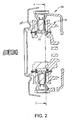
- Figure 2 is a cross sectional view of the alternator 10 and shows the stator 30, the one rotor disc 20 and the other rotor disc 20'.
- the rotor disc 20 is an annular disc formed of a ferrous material, such as electromagnetic steel.
- the disc 20 is formed with peripheral retaining structure in the form of a continuous peripheral lip 22 that projects from the one of its surfaces that is for placing adjacent the stator 30.
- the disc 20 is also formed with radially inner structure in the form of a continuous radially inner lip 24 that projects from the same surface of the disc 20.
- the rotor disc 20 includes twelve magnets 50 positioned on the surface of the disc 20, and a spider 40 fixed to that surface.
- the magnets 50 are rare earth permanent magnets formed of neodymium-iron-boron.
- the magnets 50 are substantially trapezium-shaped plates, having a long side substantially parallel to a short side with two mutually-oblique sides extending therebetween.
- the long side is, however, shaped so as to be arcuate and of a radius that is substantially the same as that of the inner diameter of the peripheral lip 22.
- each magnet 50 resembles a sector, but with a triangular tip portion removed.
- the magnets 50 are circumferentially distributed about the disc 20 with a constant pitch angle and orientated such that each has its arcuate side adjacent the peripheral lip 22.
- each magnet 50 When positioned on the surface of the disc 20, all of the sides of each magnet 50 project perpendicularly from the surface, with the exception of the radially innermost side, shown at 52 on Figures 3A and 3B .
- the radially innermost side 52 which extends tangentially when in position on the disc 20, is inclined to the perpendicular from the surface of the disc so as to be oblique thereto.
- the radially innermost side 52 forms an angle of 15 degrees with the perpendicular and such that the magnet face that is adjacent the disc surface projects further from the peripheral lip 22 than does the magnet face that is spaced from the surface.
- each magnet 50 has three sides which may be termed "perpendicular" and one side, the radially innermost side 52, which may be termed "oblique".
- Each magnet is fixed in position on the surface of the disc 20 by an adhesive.
- the spider 40 is for use in retaining the magnets 50 in position on the rotor disc 20.
- the spider 40 is formed from nylon and is shaped so as to have an inner annular portion 42, with a series of circumferentially-distributed arms 44 projecting radially outwards therefrom, as can be seen more clearly from figure 4 .
- the spider 40 is mounted to the surface of the disc 20 such that the inner diameter of the annular portion 42 of the spider 40 lies around and adjacent the radially inner lip 24.
- the arms 44 of the spider are for interdigitating with the magnets 50 and so the spider 40 is orientated such that each juxtaposed pair of the magnets 50 have a respective arm 44 therebetween.
- the sides of each of the spider arms 44 are perpendicular to the surface of the disc 20 and the width of each arm 44 is such that it abuts the adjacent, perpendicular and generally radial side of each of the respective juxtaposed pair of magnets 50.
- Figure 4 allows more of the detail of the shape of the spider 40 to be understood.
- the inner annulus 42 of the spider 40 has radially outer sides 42a that, in contrast to the sides of the arms 44, are not perpendicular to the surface of the disc 20 when the spider 40 is mounted thereon. Instead, the radially outer sides 42a are oblique to the surface so as to cooperate with and be in face-to-face abutment with the oblique radially inner sides 52 of the magnets 50.
- the radially outer sides 42a of the spider 40 also make an angle of 15 degrees with a perpendicular to the disc surface. The abutment is such that the magnets 50 are urged against the peripheral lip 22 of the disc 20.
- the spider is fixed in position by the provision of a number of rivets, shown at 46 in Figure 1 , each of which passes through a respective rivet hole, shown at 47 in Figures 1 and 4 , formed through each arm 44 of the spider 40 and through a cooperating hole (not shown) formed through the rotor disc 20.
- the spider 40 also includes a series of air holes 48 formed through the annulus 42 thereof, each in-line with a respective one of the arms 44. Each of these air holes 48 is co-axial with a respective cooperating hole (not shown) in the rotor disc 20 and is for admitting cooling air therethrough during operation of the alternator 10.
- the annulus 42 of the spider 40 also includes a series of cut-outs 49.
- Each cut-out 49 is a radial channel through the annulus 42, such that the annulus 42 is of reduced thickness in the region of each cut-out 49.
- Each cut-out 49 is formed into the surface of the spider 40 that is not for placing against the surface of the disc 20.
- a respective cut-out 49 is formed mid-way between each juxtaposed pair of the arms 44.
- a further rivet hole 49a is formed though the base of the channel that is defined by each cut-out 49, that is to say: through material of the annulus 42, in the region of each cut-out 49.
- the disc 20 also includes a series of wedge members in the form of inserts 60.
- Each insert 60 is a block, formed from aluminium, that is shaped and arranged to be a sliding fit, in a radial direction, in one of the cut-outs 49. All of the sides of each insert 60 are at right angles to one another or parallel to one another, apart from one face 62 which is oblique.
- Each insert 60 is arranged such that, when fitted in a cut-out 49, the oblique face 62 can be positioned radially outwards, with respect to the annulus 42 of the spider 40.
- each insert 60 In such a position, the oblique face 49 of each insert 60 is a co-planar continuation of a respective oblique radially-outer side 42a of the annulus 42.
- the oblique side 62 of each insert 60 is also in face-to-face abutment with the oblique face 52 of a respective one of the magnets 50.
- Each insert 60 includes a rivet-receiving fixing hole 64 for fixing the insert 60 to the annulus 42 of the spider 40 and to the rotor disc 20.
- An insert-retaining rivet shown at 66 in Figure 1 , is riveted through the fixing hole 64 of each insert 60 and through a respective one of the further holes 49a in the annulus 42 and through a respective cooperating hole formed through the rotor disc 20.
- the fixing holes 64 are counter-sunk to accommodate the rivet head portions within external contours of the insert 60.
- the fixing holes 64, including the counter sunk portions thereof, are elongated in a direction that is radial with respect to the annulus 42 when the inserts 60 are fitted thereto.
- each insert 60 is formed with grooves extending in a direction that is substantially tangential when the insert 60 is fitted to the annulus 42.
- the grooves are formed in a knurling operation. The provision of the grooves increases friction between the inserts 60 and the annulus 42, thereby promoting fixation of the former relative to the latter.
- the rotor disc 20 In operation of the alternator 10, the rotor disc 20 is rotated at high speed.
- the magnets 50 are therefore subjected (from the frame of reference of the rotor disc) to a radially outwards centrifugal force during rotation, to tangential forces when speeding up and slowing down and to axial forces as a result of electromagnetic interaction with surrounding structure.
- Radial retention is provided by the peripheral lip 22 in reaction to the centrifugal force
- tangential retention is provided by the arms 44 of the spider 40 in reaction to the tangential forces
- axial retention, at least of the radially innermost part of each magnet 50, is provided by the inserts 60, and specifically by the reaction of the oblique faces 62 thereof against the cooperating oblique sides 52 of the magnets 50.
- each magnet 50 By axially retaining at least the radially innermost part of each magnet 50, the tendency of each magnet 50 to rotate about an axis tangential to the disc such that their radially innermost ends lift from the surface of the disc 20 is resisted. Thus, the magnets are retained in position during operation.
- the spider 40 of the previously-described embodiment is modified.
- the modified spider is modified such that each cut-out therethrough forms a blind channel in the annulus that terminates in a radially inner wall.
- Each radially inner wall serves as an abutment against which the respective insert may abut when it abuts against the respective magnet.
- the insert acts as a wedge between the wall and the magnet.
- each modified insert is elongated in a radial direction and has a radially inner face that mirrors its radially outer face in being oblique to a perpendicular to the surface of disc.
- Each insert is arranged such that, when its radially outer face abuts the respective magnet, its radially inner face abuts the radially inner lip of the disc.
- the inserts act as wedges; but this time they act as wedges between the radially inner lip and the magnets.
- a radially outer surface of the radially inner lip may also be oblique to a perpendicular to the surface of the disc and so as to cooperate with the oblique and radially inner face of each modified insert.
Landscapes
- Engineering & Computer Science (AREA)
- Power Engineering (AREA)
- Permanent Field Magnets Of Synchronous Machinery (AREA)
- Holding Or Fastening Of Disk On Rotational Shaft (AREA)
- Insulation, Fastening Of Motor, Generator Windings (AREA)
- Iron Core Of Rotating Electric Machines (AREA)
Abstract
Description
- This invention relates to a rotor disc for an electrical machine and to retaining means for such a rotor disc. This invention also relates to retaining means for a rotor disc for an electrical machine.
- The document
US 5,831,365 relates to a detachable magnet carrier for a permanent magnet motor. A permanent magnet is placed in a container which then receives a cover, and a rotor has recesses which have a size and shape complementary to the size and shape of the magnet carrier assembly. By providing the magnet carrier assembly with a key which is received in a mating groove in a rotor surface, electromagnetic force is transferred to the rotor. - Document
US 3,320,453 relates to an axial air gap dynamo electric machine with a disc rotor. An annular body of ceramic magnet material is supported by a casing wall against centrifugal force produced upon rotation of the structure. - Document
US 4,864,175 relates to a rotor for an electric motor. A supporting disc has window-like openings corresponding to the contour of flat magnets. Flat magnets are seated between the supporting discs to secure them against the effects of centrifugal forces. - International publication
WO 02/056443 - Although the arrangement disclosed in
WO 02/056443 - It is an object of this invention to address this problem.
- According to one aspect of the invention, there is provided a rotor disc for an electrical machine, the rotor disc including a series of magnetisable members arranged in a circumferential series on a surface thereof and against peripheral retaining structure of the disc, and further including a retaining means fixable to the surface and arranged for assisting in retaining the members at least axially on the surface when so fixed, the retaining means comprising a spider, the spider comprising an annulus and a series of radially projecting arms, characterised in that:
- the spider comprises a series of cut-outs through the annulus such that the annulus is of reduced thickness in the region of each cut-out; and
- the retaining means further comprises a series of wedge members shaped and arranged to fit in the cut-outs so as to abut a substantially circumferentially or substantially tangentially extending and radially inner part of each magnetisable member thereby to provide the axial retention.
- It has been found that, in operation, larger magnets fixed to a rotor disc using a known technique, such as that disclosed in
WO 02/056443 - Secondary retaining means may be provided for fixing the magnetisable members to the surface. For example the magnetisable members may also be fixed to the surface by an adhesive.
- The retaining means may also be arranged to abut the members so as to retain the magnetisable members tangentially. Tangential retention may be provided by the retaining means being arranged to abut substantially radially-extending sides of the magnetisable members.
- Preferably the retaining means and the magnetisable members are arranged to have mutually abutting surfaces that are oblique to the surface of the disc. Some or all of the mutually abutting surfaces may extend substantially circumferentially, or substantially tangentially, such that the axial retention is provided by abutment therebetween. Preferably, the surface of each member that is a mutually abutting surface is a radially innermost end of the member. This is advantageous in urging each magnetisable member both axially against the surface of the disc and radially against the peripheral retaining structure of the disc, thereby providing both axial and radial retention of at least the radially innermost part of the member. In a preferred embodiment of this invention, the mutually abutting surfaces make an angle of between about 70 and 80 degrees with the surface of the disc. Most preferably, the angle is about 75 degrees.
- At least some of the mutually-abutting surfaces may extend substantially radially, such that the radial retention, and additional axial retention, is provided by abutment therebetween.
- The retaining means may be arranged such that it abuts a surface of each magnetisable member that is opposite to a surface thereof that is against the surface of the disc, the retaining means thereby providing the axial retention.
- The retaining means may include supporting means and abutment means, the supporting means being for fixing to the surface of the disc and the abutment means for fixing to the supporting means and for abutting the magnetisable members. The abutment means may be of a stronger material that the supporting means. Preferably the abutment means is of a non-ferrous metal, such as aluminium and the supporting means is of a plastic material, such as nylon. Preferably the abutment means is arranged such that, when fixed to the supporting means, it presents a, or a respective, surface for the said oblique mutual abutment with the or each of the members.
- The plurality of wedge members are preferably fitted to the supporting means such that fixing the supporting means to the disc results in each wedge member presenting a substantially tangential surface that is oblique to the surface of the disc to a respective one of the magnetisable members. Preferably the magnetisable members are arranged with a radially inner and cooperating substantially tangential surface that is oblique to the surface of the disc and that cooperates with the oblique surface of each wedge member to result in the axial retention of the member when the supporting means is fixed to the disc.
- The abutment means may include another surface or surfaces, substantially opposite the first and for abutment against the supporting means or against radially inner structure of the disc. The other surface of the abutment means may also be oblique to the surface of the disc and such that fixing the abutment means to the supporting means, and/or the supporting means to the disc, causes the abutment means to be urged against the member. The supporting means or the radially inner structure of the disc may be provided with a cooperating surface or surfaces that are oblique to the surface of the disc and for cooperating with the other surface of the abutment means.
- The spider is preferably for mounting coaxially with the disc such that each arm projects between and abuts each of a respective juxtaposed pair of the members, thereby providing the tangential retention. The plurality of wedge members is preferably for fitting to the annulus of the spider such that fixing the spider to the disc results in each wedge member presenting a substantially tangential surface that is oblique to the surface of the disc and to a respective one of the magnetisable members. Preferably the magnetisable members are arranged with a substantially tangential surface that is oblique to the surface of the disc and that cooperates with the oblique surface of each wedge member to result in the axial retention of the magnetisable member when the spider is fixed to the disc.
- The magnetisable members are preferable rare earth magnets, such as those formed from neodymium-iron-boron.
- Specific embodiments of this invention are now described by way of example only and with reference to the accompanying figures, in which:
-
Figure 1 is a sectional view through an alternator showing a plan view of a rotor disc of the alternator; -
Figure 2 is sectional view though the alternator, the section being through a radial plane of the rotor disc; -
Figure 3A is a side elevation of a magnet for fitting to the rotor disc; -
Figure 3B is a plan view of the magnet; -
Figure 4 is a perspective view of a spider for fitting to the rotor disc; -
Figure 5A is a plan view of an insert for fitting to the spider; and -
Figure 5B is a sectional view through the insert. -
Figure 1 shows arotor disc 20 of a permanent magnet,axial flux alternator 10. Thealternator 10 is of the type that has a toroidal stator sandwiched between a pair of co-axial rotor discs, of which therotor disc 20 is one.Figure 2 is a cross sectional view of thealternator 10 and shows thestator 30, the onerotor disc 20 and the other rotor disc 20'. - With reference to
Figure 1 , therotor disc 20 is an annular disc formed of a ferrous material, such as electromagnetic steel. Thedisc 20 is formed with peripheral retaining structure in the form of a continuousperipheral lip 22 that projects from the one of its surfaces that is for placing adjacent thestator 30. Thedisc 20 is also formed with radially inner structure in the form of a continuous radiallyinner lip 24 that projects from the same surface of thedisc 20. - As can also be seen from
Figure 1 , therotor disc 20 includes twelvemagnets 50 positioned on the surface of thedisc 20, and aspider 40 fixed to that surface. - The
magnets 50 are rare earth permanent magnets formed of neodymium-iron-boron. Themagnets 50 are substantially trapezium-shaped plates, having a long side substantially parallel to a short side with two mutually-oblique sides extending therebetween. The long side is, however, shaped so as to be arcuate and of a radius that is substantially the same as that of the inner diameter of theperipheral lip 22. Thus, in plan-form, eachmagnet 50 resembles a sector, but with a triangular tip portion removed. Themagnets 50 are circumferentially distributed about thedisc 20 with a constant pitch angle and orientated such that each has its arcuate side adjacent theperipheral lip 22. - When positioned on the surface of the
disc 20, all of the sides of eachmagnet 50 project perpendicularly from the surface, with the exception of the radially innermost side, shown at 52 onFigures 3A and 3B . With reference to these two figures, the radiallyinnermost side 52, which extends tangentially when in position on thedisc 20, is inclined to the perpendicular from the surface of the disc so as to be oblique thereto. The radiallyinnermost side 52 forms an angle of 15 degrees with the perpendicular and such that the magnet face that is adjacent the disc surface projects further from theperipheral lip 22 than does the magnet face that is spaced from the surface. Thus, eachmagnet 50 has three sides which may be termed "perpendicular" and one side, the radiallyinnermost side 52, which may be termed "oblique". - Each magnet is fixed in position on the surface of the
disc 20 by an adhesive. - The
spider 40 is for use in retaining themagnets 50 in position on therotor disc 20. Thespider 40 is formed from nylon and is shaped so as to have an innerannular portion 42, with a series of circumferentially-distributedarms 44 projecting radially outwards therefrom, as can be seen more clearly fromfigure 4 . With reference toFigure 3 , thespider 40 is mounted to the surface of thedisc 20 such that the inner diameter of theannular portion 42 of thespider 40 lies around and adjacent the radiallyinner lip 24. Thearms 44 of the spider are for interdigitating with themagnets 50 and so thespider 40 is orientated such that each juxtaposed pair of themagnets 50 have arespective arm 44 therebetween. The sides of each of thespider arms 44 are perpendicular to the surface of thedisc 20 and the width of eacharm 44 is such that it abuts the adjacent, perpendicular and generally radial side of each of the respective juxtaposed pair ofmagnets 50. -
Figure 4 allows more of the detail of the shape of thespider 40 to be understood. With reference toFigure 4 , theinner annulus 42 of thespider 40 has radiallyouter sides 42a that, in contrast to the sides of thearms 44, are not perpendicular to the surface of thedisc 20 when thespider 40 is mounted thereon. Instead, the radiallyouter sides 42a are oblique to the surface so as to cooperate with and be in face-to-face abutment with the oblique radiallyinner sides 52 of themagnets 50. Thus, the radiallyouter sides 42a of thespider 40 also make an angle of 15 degrees with a perpendicular to the disc surface. The abutment is such that themagnets 50 are urged against theperipheral lip 22 of thedisc 20. - The spider is fixed in position by the provision of a number of rivets, shown at 46 in
Figure 1 , each of which passes through a respective rivet hole, shown at 47 inFigures 1 and4 , formed through eacharm 44 of thespider 40 and through a cooperating hole (not shown) formed through therotor disc 20. Thespider 40 also includes a series ofair holes 48 formed through theannulus 42 thereof, each in-line with a respective one of thearms 44. Each of theseair holes 48 is co-axial with a respective cooperating hole (not shown) in therotor disc 20 and is for admitting cooling air therethrough during operation of thealternator 10. - With reference to
Figure 4 , theannulus 42 of thespider 40 also includes a series of cut-outs 49. Each cut-out 49 is a radial channel through theannulus 42, such that theannulus 42 is of reduced thickness in the region of each cut-out 49. Each cut-out 49 is formed into the surface of thespider 40 that is not for placing against the surface of thedisc 20. A respective cut-out 49 is formed mid-way between each juxtaposed pair of thearms 44. A further rivet hole 49a is formed though the base of the channel that is defined by each cut-out 49, that is to say: through material of theannulus 42, in the region of each cut-out 49. - With reference to
Figure 1 , thedisc 20 also includes a series of wedge members in the form ofinserts 60. Eachinsert 60 is a block, formed from aluminium, that is shaped and arranged to be a sliding fit, in a radial direction, in one of the cut-outs 49. All of the sides of eachinsert 60 are at right angles to one another or parallel to one another, apart from oneface 62 which is oblique. Eachinsert 60 is arranged such that, when fitted in a cut-out 49, theoblique face 62 can be positioned radially outwards, with respect to theannulus 42 of thespider 40. In such a position, theoblique face 49 of eachinsert 60 is a co-planar continuation of a respective oblique radially-outer side 42a of theannulus 42. Thus, theoblique side 62 of eachinsert 60 is also in face-to-face abutment with theoblique face 52 of a respective one of themagnets 50. - Each
insert 60 includes a rivet-receivingfixing hole 64 for fixing theinsert 60 to theannulus 42 of thespider 40 and to therotor disc 20. An insert-retaining rivet, shown at 66 inFigure 1 , is riveted through the fixinghole 64 of eachinsert 60 and through a respective one of the further holes 49a in theannulus 42 and through a respective cooperating hole formed through therotor disc 20. With reference toFigures 5A and 5B , the fixing holes 64 are counter-sunk to accommodate the rivet head portions within external contours of theinsert 60. The fixing holes 64, including the counter sunk portions thereof, are elongated in a direction that is radial with respect to theannulus 42 when theinserts 60 are fitted thereto. This is to allow some radial variation of the position of each insert 60 relative to themagnets 50, thereby ensuring that each insert 60 can be placed in abutment with itsrespective magnet 50, before thatinsert 60 is riveted into position on theannulus 42 and therotor disc 20. As shown inFigure 5B , the underside of eachinsert 60, that is for contacting theannulus 42, is formed with grooves extending in a direction that is substantially tangential when theinsert 60 is fitted to theannulus 42. The grooves are formed in a knurling operation. The provision of the grooves increases friction between theinserts 60 and theannulus 42, thereby promoting fixation of the former relative to the latter. - The abutment between two
inserts 60 and theirrespective magnets 50, and the riveting of those twoinserts 60 to theannulus 42 of the spider and therotor disc 20 is shown in the section view of thealternator 10 ofFigure 2 . - In operation of the
alternator 10, therotor disc 20 is rotated at high speed. Themagnets 50 are therefore subjected (from the frame of reference of the rotor disc) to a radially outwards centrifugal force during rotation, to tangential forces when speeding up and slowing down and to axial forces as a result of electromagnetic interaction with surrounding structure. Radial retention is provided by theperipheral lip 22 in reaction to the centrifugal force, tangential retention is provided by thearms 44 of thespider 40 in reaction to the tangential forces, and axial retention, at least of the radially innermost part of eachmagnet 50, is provided by theinserts 60, and specifically by the reaction of the oblique faces 62 thereof against the cooperatingoblique sides 52 of themagnets 50. By axially retaining at least the radially innermost part of eachmagnet 50, the tendency of eachmagnet 50 to rotate about an axis tangential to the disc such that their radially innermost ends lift from the surface of thedisc 20 is resisted. Thus, the magnets are retained in position during operation. - In a first alternative embodiment of this invention which is not illustrated, the
spider 40 of the previously-described embodiment is modified. The modified spider is modified such that each cut-out therethrough forms a blind channel in the annulus that terminates in a radially inner wall. Each radially inner wall serves as an abutment against which the respective insert may abut when it abuts against the respective magnet. In other words, the insert acts as a wedge between the wall and the magnet. - In a second alternative embodiment of this invention which is also not illustrated, the spider is the same as that 40 described above with reference to the drawings, but the inserts are modified. Each modified insert is elongated in a radial direction and has a radially inner face that mirrors its radially outer face in being oblique to a perpendicular to the surface of disc. Each insert is arranged such that, when its radially outer face abuts the respective magnet, its radially inner face abuts the radially inner lip of the disc. Thus, and again, the inserts act as wedges; but this time they act as wedges between the radially inner lip and the magnets. It is envisaged that a radially outer surface of the radially inner lip may also be oblique to a perpendicular to the surface of the disc and so as to cooperate with the oblique and radially inner face of each modified insert.
Claims (15)
- A rotor disc (20) for an electrical machine, the rotor disc including a series of magnetisable members (50) arranged in a circumferential series on a surface thereof and against peripheral retaining structure (22) of the disc, and further including a retaining means fixable to the surface and arranged for assisting in retaining the members at least axially on the surface when so fixed, the retaining means comprising a spider (40), the spider comprising an annulus (42) and a series of radially projecting arms (44), characterised in that:the spider comprises a series of cut-outs (49) through the annulus (42) such that the annulus is of reduced thickness in the region of each cut-out; andthe retaining means further comprises a series of wedge members (60) shaped and arranged to fit in the cut-outs so as to abut a substantially circumferentially or substantially tangentially extending and radially inner part of each magnetisable member thereby to provide the axial retention.
- A rotor disc according to claim 1, wherein the spider is arranged to abut the magnetisable members so as to retain the magnetisable members tangentially.
- A rotor disc according to claim 2, wherein said tangential retention is provided by the spider being arranged to abut substantially radially-extending sides of the magnetisable members.
- A rotor disc according to any preceding claim, wherein the retaining means and the magnetisable members are arranged to have mutually abutting surfaces that are oblique to the surface of the disc.
- A rotor disc according to claim 4, wherein some or all of the mutually abutting surfaces extend substantially circumferentially, or substantially tangentially, such that the axial retention is provided by abutment therebetween.
- A rotor disc according to claim 4 or claim 5, wherein the surface of each magnetisable member that is a mutually abutting surface is a radially innermost end of the magnetisable member.
- A rotor disc according to any one of claims 4 to 6, wherein the mutually abutting surfaces make an angle of between about 70 and 80 degrees with the surface of the disc.
- A rotor disc according to any one of claims 4 to 7, wherein at least some of the mutually-abutting surfaces extend substantially radially, such that the radial retention, and additional axial retention, is provided by abutment therebetween.
- A rotor disc according to any preceding claim, wherein the retaining means is arranged so as to abut a surface of each magnetisable member that is opposite to a surface thereof that is against the surface of the disc, the retaining means thereby providing the axial retention.
- A rotor disc according to any of the preceding claims, wherein the wedge members are of a stronger material that the spider.
- A rotor disc assembly according to any of the preceding claims, wherein each wedge member presents a substantially tangential surface that is oblique to the surface of the disc and to a respective one of the magnetisable members.
- A rotor disc assembly according to claim 11, wherein the magnetisable members are arranged with a radially inner and cooperating substantially tangential surface that is oblique to the surface of the disc and that cooperates with the oblique surface of each wedge member to result in the axial retention of the magnetisable members when the spider is fixed to the disc.
- A rotor disc assembly according to claim 11 or 12 wherein each wedge member includes another surface or surfaces, substantially opposite the first said surface of each wedge member, the other surface or surfaces being for abutment against the spider or against radially inner structure of the disc.
- A rotor disc according to claim 13 wherein the spider or the radially inner structure of the disc is provided with a cooperating surface or surfaces that are oblique to the surface of the disc and for cooperating with the said other surface of the wedge members.
- A rotor disc according to any of the preceding claims wherein the spider is for mounting coaxially with the disc such that each arm projects between and abuts each of a respective juxtaposed pair of the magnetisable members, thereby providing the tangential retention.
Applications Claiming Priority (2)
| Application Number | Priority Date | Filing Date | Title |
|---|---|---|---|
| GBGB0317633.6A GB0317633D0 (en) | 2003-07-28 | 2003-07-28 | A rotor disc for an electrical machine,and retaining means |
| GB0317633 | 2003-07-28 |
Publications (2)
| Publication Number | Publication Date |
|---|---|
| EP1503478A1 EP1503478A1 (en) | 2005-02-02 |
| EP1503478B1 true EP1503478B1 (en) | 2010-03-31 |
Family
ID=27772838
Family Applications (1)
| Application Number | Title | Priority Date | Filing Date |
|---|---|---|---|
| EP04254526A Expired - Lifetime EP1503478B1 (en) | 2003-07-28 | 2004-07-28 | A rotor disc for an electrical machine, and retaining means |
Country Status (4)
| Country | Link |
|---|---|
| EP (1) | EP1503478B1 (en) |
| AT (1) | ATE463068T1 (en) |
| DE (1) | DE602004026249D1 (en) |
| GB (1) | GB0317633D0 (en) |
Families Citing this family (2)
| Publication number | Priority date | Publication date | Assignee | Title |
|---|---|---|---|---|
| GB0821815D0 (en) | 2008-11-28 | 2009-01-07 | Cummins Generator Technologies | Rotating electrical machine |
| GB2511320A (en) * | 2013-02-27 | 2014-09-03 | Yasa Motors Ltd | Axial flux motor |
Family Cites Families (4)
| Publication number | Priority date | Publication date | Assignee | Title |
|---|---|---|---|---|
| US3320453A (en) * | 1959-09-09 | 1967-05-16 | Garrett Corp | Axial air gap dynamoelectric machine with a disc rotor |
| DE3713610A1 (en) * | 1987-04-23 | 1988-11-10 | Heldt & Rossi Servoelektronik | ROTOR FOR ELECTRIC MOTOR |
| US5691589A (en) * | 1995-06-30 | 1997-11-25 | Kaman Electromagnetics Corporation | Detachable magnet carrier for permanent magnet motor |
| GB0100635D0 (en) * | 2001-01-10 | 2001-02-21 | Newage Int Ltd | Apparatus for and method of locating magnets |
-
2003
- 2003-07-28 GB GBGB0317633.6A patent/GB0317633D0/en not_active Ceased
-
2004
- 2004-07-28 EP EP04254526A patent/EP1503478B1/en not_active Expired - Lifetime
- 2004-07-28 DE DE602004026249T patent/DE602004026249D1/en not_active Expired - Lifetime
- 2004-07-28 AT AT04254526T patent/ATE463068T1/en not_active IP Right Cessation
Also Published As
| Publication number | Publication date |
|---|---|
| EP1503478A1 (en) | 2005-02-02 |
| DE602004026249D1 (en) | 2010-05-12 |
| GB0317633D0 (en) | 2003-08-27 |
| ATE463068T1 (en) | 2010-04-15 |
Similar Documents
| Publication | Publication Date | Title |
|---|---|---|
| US11005322B2 (en) | Rotor assemblies for axial flux machines | |
| US6384504B1 (en) | Electric machine with a rotor constructed of permanent magnets and magnetic flux guides | |
| EP1193827B1 (en) | Rotor structure for permanent-magnet motor | |
| KR100249099B1 (en) | Detachable magnet carrier for permanent magnet motor | |
| EP1286446B1 (en) | Permanent magnet rotor and permanent magnet machine | |
| US4853573A (en) | Eddy current brake assembly | |
| CA1096921A (en) | Magneto rotor construction | |
| US7109629B2 (en) | Rotor disc for an electrical machine and a retainer | |
| EP1350300B1 (en) | Method of fixing magnetisable members to a rotor disc and corresponding rotor disc | |
| US8304951B2 (en) | Dynamoelectric machine | |
| EP0831243A3 (en) | Clamshell cup friction article and method of refurbishment | |
| EP1567323B1 (en) | Belt and tread drum | |
| EP0216024B1 (en) | External magnet flywheel mounting | |
| EP1503478A1 (en) | A rotor disc for an electrical machine, and retaining means | |
| AU2020382759B2 (en) | Improved rotor assemblies for axial flux machines | |
| CA1138788A (en) | Friction wear pad and method and means for fastening said pad to a disk core member | |
| US3265913A (en) | Magnetic retaining means | |
| JPS61293142A (en) | High-speed synchronous rotary machine with rotor comprising permanent magnet for producing magnetic field vartical to diametrical direction | |
| CA2017474C (en) | End ring damping structure for dynamoelectric machines | |
| GB2643419A (en) | Brake rotor | |
| KR19990009910U (en) | Permanent Magnet Motor Rotor | |
| JPH11336796A (en) | Electromagnetic clutch |
Legal Events
| Date | Code | Title | Description |
|---|---|---|---|
| PUAI | Public reference made under article 153(3) epc to a published international application that has entered the european phase |
Free format text: ORIGINAL CODE: 0009012 |
|
| AK | Designated contracting states |
Kind code of ref document: A1 Designated state(s): AT BE BG CH CY CZ DE DK EE ES FI FR GB GR HU IE IT LI LU MC NL PL PT RO SE SI SK TR |
|
| AX | Request for extension of the european patent |
Extension state: AL HR LT LV MK |
|
| 17P | Request for examination filed |
Effective date: 20050715 |
|
| AKX | Designation fees paid |
Designated state(s): AT BE BG CH CY CZ DE DK EE ES FI FR GB GR HU IE IT LI LU MC NL PL PT RO SE SI SK TR |
|
| RAP1 | Party data changed (applicant data changed or rights of an application transferred) |
Owner name: CUMMINS GENERATOR TECHNOLOGIES LIMITED |
|
| 17Q | First examination report despatched |
Effective date: 20090310 |
|
| GRAP | Despatch of communication of intention to grant a patent |
Free format text: ORIGINAL CODE: EPIDOSNIGR1 |
|
| GRAS | Grant fee paid |
Free format text: ORIGINAL CODE: EPIDOSNIGR3 |
|
| GRAA | (expected) grant |
Free format text: ORIGINAL CODE: 0009210 |
|
| AK | Designated contracting states |
Kind code of ref document: B1 Designated state(s): AT BE BG CH CY CZ DE DK EE ES FI FR GB GR HU IE IT LI LU MC NL PL PT RO SE SI SK TR |
|
| REG | Reference to a national code |
Ref country code: GB Ref legal event code: FG4D Ref country code: CH Ref legal event code: EP |
|
| REG | Reference to a national code |
Ref country code: IE Ref legal event code: FG4D |
|
| REF | Corresponds to: |
Ref document number: 602004026249 Country of ref document: DE Date of ref document: 20100512 Kind code of ref document: P |
|
| REG | Reference to a national code |
Ref country code: NL Ref legal event code: VDEP Effective date: 20100331 |
|
| PG25 | Lapsed in a contracting state [announced via postgrant information from national office to epo] |
Ref country code: AT Free format text: LAPSE BECAUSE OF FAILURE TO SUBMIT A TRANSLATION OF THE DESCRIPTION OR TO PAY THE FEE WITHIN THE PRESCRIBED TIME-LIMIT Effective date: 20100331 Ref country code: SI Free format text: LAPSE BECAUSE OF FAILURE TO SUBMIT A TRANSLATION OF THE DESCRIPTION OR TO PAY THE FEE WITHIN THE PRESCRIBED TIME-LIMIT Effective date: 20100331 Ref country code: PL Free format text: LAPSE BECAUSE OF FAILURE TO SUBMIT A TRANSLATION OF THE DESCRIPTION OR TO PAY THE FEE WITHIN THE PRESCRIBED TIME-LIMIT Effective date: 20100331 Ref country code: FI Free format text: LAPSE BECAUSE OF FAILURE TO SUBMIT A TRANSLATION OF THE DESCRIPTION OR TO PAY THE FEE WITHIN THE PRESCRIBED TIME-LIMIT Effective date: 20100331 |
|
| PG25 | Lapsed in a contracting state [announced via postgrant information from national office to epo] |
Ref country code: BE Free format text: LAPSE BECAUSE OF FAILURE TO SUBMIT A TRANSLATION OF THE DESCRIPTION OR TO PAY THE FEE WITHIN THE PRESCRIBED TIME-LIMIT Effective date: 20100331 Ref country code: SE Free format text: LAPSE BECAUSE OF FAILURE TO SUBMIT A TRANSLATION OF THE DESCRIPTION OR TO PAY THE FEE WITHIN THE PRESCRIBED TIME-LIMIT Effective date: 20100331 Ref country code: RO Free format text: LAPSE BECAUSE OF FAILURE TO SUBMIT A TRANSLATION OF THE DESCRIPTION OR TO PAY THE FEE WITHIN THE PRESCRIBED TIME-LIMIT Effective date: 20100331 Ref country code: NL Free format text: LAPSE BECAUSE OF FAILURE TO SUBMIT A TRANSLATION OF THE DESCRIPTION OR TO PAY THE FEE WITHIN THE PRESCRIBED TIME-LIMIT Effective date: 20100331 Ref country code: ES Free format text: LAPSE BECAUSE OF FAILURE TO SUBMIT A TRANSLATION OF THE DESCRIPTION OR TO PAY THE FEE WITHIN THE PRESCRIBED TIME-LIMIT Effective date: 20100712 Ref country code: EE Free format text: LAPSE BECAUSE OF FAILURE TO SUBMIT A TRANSLATION OF THE DESCRIPTION OR TO PAY THE FEE WITHIN THE PRESCRIBED TIME-LIMIT Effective date: 20100331 Ref country code: CY Free format text: LAPSE BECAUSE OF FAILURE TO SUBMIT A TRANSLATION OF THE DESCRIPTION OR TO PAY THE FEE WITHIN THE PRESCRIBED TIME-LIMIT Effective date: 20100331 |
|
| PG25 | Lapsed in a contracting state [announced via postgrant information from national office to epo] |
Ref country code: CZ Free format text: LAPSE BECAUSE OF FAILURE TO SUBMIT A TRANSLATION OF THE DESCRIPTION OR TO PAY THE FEE WITHIN THE PRESCRIBED TIME-LIMIT Effective date: 20100331 Ref country code: SK Free format text: LAPSE BECAUSE OF FAILURE TO SUBMIT A TRANSLATION OF THE DESCRIPTION OR TO PAY THE FEE WITHIN THE PRESCRIBED TIME-LIMIT Effective date: 20100331 |
|
| PG25 | Lapsed in a contracting state [announced via postgrant information from national office to epo] |
Ref country code: DK Free format text: LAPSE BECAUSE OF FAILURE TO SUBMIT A TRANSLATION OF THE DESCRIPTION OR TO PAY THE FEE WITHIN THE PRESCRIBED TIME-LIMIT Effective date: 20100331 Ref country code: PT Free format text: LAPSE BECAUSE OF FAILURE TO SUBMIT A TRANSLATION OF THE DESCRIPTION OR TO PAY THE FEE WITHIN THE PRESCRIBED TIME-LIMIT Effective date: 20100802 |
|
| PLBE | No opposition filed within time limit |
Free format text: ORIGINAL CODE: 0009261 |
|
| STAA | Information on the status of an ep patent application or granted ep patent |
Free format text: STATUS: NO OPPOSITION FILED WITHIN TIME LIMIT |
|
| PG25 | Lapsed in a contracting state [announced via postgrant information from national office to epo] |
Ref country code: MC Free format text: LAPSE BECAUSE OF NON-PAYMENT OF DUE FEES Effective date: 20100731 |
|
| REG | Reference to a national code |
Ref country code: CH Ref legal event code: PL |
|
| 26N | No opposition filed |
Effective date: 20110104 |
|
| PG25 | Lapsed in a contracting state [announced via postgrant information from national office to epo] |
Ref country code: IT Free format text: LAPSE BECAUSE OF FAILURE TO SUBMIT A TRANSLATION OF THE DESCRIPTION OR TO PAY THE FEE WITHIN THE PRESCRIBED TIME-LIMIT Effective date: 20100331 |
|
| REG | Reference to a national code |
Ref country code: FR Ref legal event code: ST Effective date: 20110331 |
|
| PG25 | Lapsed in a contracting state [announced via postgrant information from national office to epo] |
Ref country code: LI Free format text: LAPSE BECAUSE OF NON-PAYMENT OF DUE FEES Effective date: 20100731 Ref country code: CH Free format text: LAPSE BECAUSE OF NON-PAYMENT OF DUE FEES Effective date: 20100731 |
|
| PG25 | Lapsed in a contracting state [announced via postgrant information from national office to epo] |
Ref country code: FR Free format text: LAPSE BECAUSE OF NON-PAYMENT OF DUE FEES Effective date: 20100802 |
|
| PG25 | Lapsed in a contracting state [announced via postgrant information from national office to epo] |
Ref country code: IE Free format text: LAPSE BECAUSE OF NON-PAYMENT OF DUE FEES Effective date: 20100728 |
|
| PG25 | Lapsed in a contracting state [announced via postgrant information from national office to epo] |
Ref country code: HU Free format text: LAPSE BECAUSE OF FAILURE TO SUBMIT A TRANSLATION OF THE DESCRIPTION OR TO PAY THE FEE WITHIN THE PRESCRIBED TIME-LIMIT Effective date: 20101001 Ref country code: BG Free format text: LAPSE BECAUSE OF FAILURE TO SUBMIT A TRANSLATION OF THE DESCRIPTION OR TO PAY THE FEE WITHIN THE PRESCRIBED TIME-LIMIT Effective date: 20100331 Ref country code: LU Free format text: LAPSE BECAUSE OF NON-PAYMENT OF DUE FEES Effective date: 20100728 |
|
| PG25 | Lapsed in a contracting state [announced via postgrant information from national office to epo] |
Ref country code: TR Free format text: LAPSE BECAUSE OF FAILURE TO SUBMIT A TRANSLATION OF THE DESCRIPTION OR TO PAY THE FEE WITHIN THE PRESCRIBED TIME-LIMIT Effective date: 20100331 |
|
| PG25 | Lapsed in a contracting state [announced via postgrant information from national office to epo] |
Ref country code: BG Free format text: LAPSE BECAUSE OF FAILURE TO SUBMIT A TRANSLATION OF THE DESCRIPTION OR TO PAY THE FEE WITHIN THE PRESCRIBED TIME-LIMIT Effective date: 20100630 |
|
| PG25 | Lapsed in a contracting state [announced via postgrant information from national office to epo] |
Ref country code: GR Free format text: LAPSE BECAUSE OF FAILURE TO SUBMIT A TRANSLATION OF THE DESCRIPTION OR TO PAY THE FEE WITHIN THE PRESCRIBED TIME-LIMIT Effective date: 20100331 |
|
| P01 | Opt-out of the competence of the unified patent court (upc) registered |
Effective date: 20230510 |
|
| PGFP | Annual fee paid to national office [announced via postgrant information from national office to epo] |
Ref country code: GB Payment date: 20230727 Year of fee payment: 20 |
|
| PGFP | Annual fee paid to national office [announced via postgrant information from national office to epo] |
Ref country code: DE Payment date: 20230727 Year of fee payment: 20 |
|
| REG | Reference to a national code |
Ref country code: DE Ref legal event code: R071 Ref document number: 602004026249 Country of ref document: DE |
|
| REG | Reference to a national code |
Ref country code: GB Ref legal event code: PE20 Expiry date: 20240727 |
|
| PG25 | Lapsed in a contracting state [announced via postgrant information from national office to epo] |
Ref country code: GB Free format text: LAPSE BECAUSE OF EXPIRATION OF PROTECTION Effective date: 20240727 |
|
| PG25 | Lapsed in a contracting state [announced via postgrant information from national office to epo] |
Ref country code: GB Free format text: LAPSE BECAUSE OF EXPIRATION OF PROTECTION Effective date: 20240727 |