EP1503423A1 - MIS power semiconductor device and method of making the same - Google Patents
MIS power semiconductor device and method of making the same Download PDFInfo
- Publication number
- EP1503423A1 EP1503423A1 EP03425526A EP03425526A EP1503423A1 EP 1503423 A1 EP1503423 A1 EP 1503423A1 EP 03425526 A EP03425526 A EP 03425526A EP 03425526 A EP03425526 A EP 03425526A EP 1503423 A1 EP1503423 A1 EP 1503423A1
- Authority
- EP
- European Patent Office
- Prior art keywords
- dielectric layer
- dielectric
- portions
- gate electrode
- manufacturing
- Prior art date
- Legal status (The legal status is an assumption and is not a legal conclusion. Google has not performed a legal analysis and makes no representation as to the accuracy of the status listed.)
- Granted
Links
Images


Classifications
-
- H—ELECTRICITY
- H10—SEMICONDUCTOR DEVICES; ELECTRIC SOLID-STATE DEVICES NOT OTHERWISE PROVIDED FOR
- H10D—INORGANIC ELECTRIC SEMICONDUCTOR DEVICES
- H10D30/00—Field-effect transistors [FET]
- H10D30/60—Insulated-gate field-effect transistors [IGFET]
- H10D30/64—Double-diffused metal-oxide semiconductor [DMOS] FETs
- H10D30/66—Vertical DMOS [VDMOS] FETs
-
- H—ELECTRICITY
- H10—SEMICONDUCTOR DEVICES; ELECTRIC SOLID-STATE DEVICES NOT OTHERWISE PROVIDED FOR
- H10D—INORGANIC ELECTRIC SEMICONDUCTOR DEVICES
- H10D30/00—Field-effect transistors [FET]
- H10D30/01—Manufacture or treatment
- H10D30/021—Manufacture or treatment of FETs having insulated gates [IGFET]
- H10D30/028—Manufacture or treatment of FETs having insulated gates [IGFET] of double-diffused metal oxide semiconductor [DMOS] FETs
- H10D30/0291—Manufacture or treatment of FETs having insulated gates [IGFET] of double-diffused metal oxide semiconductor [DMOS] FETs of vertical DMOS [VDMOS] FETs
-
- H—ELECTRICITY
- H10—SEMICONDUCTOR DEVICES; ELECTRIC SOLID-STATE DEVICES NOT OTHERWISE PROVIDED FOR
- H10D—INORGANIC ELECTRIC SEMICONDUCTOR DEVICES
- H10D64/00—Electrodes of devices having potential barriers
- H10D64/01—Manufacture or treatment
- H10D64/021—Manufacture or treatment using multiple gate spacer layers, e.g. bilayered sidewall spacers
-
- H—ELECTRICITY
- H10—SEMICONDUCTOR DEVICES; ELECTRIC SOLID-STATE DEVICES NOT OTHERWISE PROVIDED FOR
- H10D—INORGANIC ELECTRIC SEMICONDUCTOR DEVICES
- H10D64/00—Electrodes of devices having potential barriers
- H10D64/20—Electrodes characterised by their shapes, relative sizes or dispositions
- H10D64/27—Electrodes not carrying the current to be rectified, amplified, oscillated or switched, e.g. gates
- H10D64/311—Gate electrodes for field-effect devices
- H10D64/411—Gate electrodes for field-effect devices for FETs
- H10D64/511—Gate electrodes for field-effect devices for FETs for IGFETs
- H10D64/514—Gate electrodes for field-effect devices for FETs for IGFETs characterised by the insulating layers
- H10D64/516—Gate electrodes for field-effect devices for FETs for IGFETs characterised by the insulating layers the thicknesses being non-uniform
-
- H—ELECTRICITY
- H10—SEMICONDUCTOR DEVICES; ELECTRIC SOLID-STATE DEVICES NOT OTHERWISE PROVIDED FOR
- H10D—INORGANIC ELECTRIC SEMICONDUCTOR DEVICES
- H10D64/00—Electrodes of devices having potential barriers
- H10D64/20—Electrodes characterised by their shapes, relative sizes or dispositions
- H10D64/27—Electrodes not carrying the current to be rectified, amplified, oscillated or switched, e.g. gates
- H10D64/311—Gate electrodes for field-effect devices
- H10D64/411—Gate electrodes for field-effect devices for FETs
- H10D64/511—Gate electrodes for field-effect devices for FETs for IGFETs
- H10D64/517—Gate electrodes for field-effect devices for FETs for IGFETs characterised by the conducting layers
- H10D64/518—Gate electrodes for field-effect devices for FETs for IGFETs characterised by the conducting layers characterised by their lengths or sectional shapes
-
- H—ELECTRICITY
- H10—SEMICONDUCTOR DEVICES; ELECTRIC SOLID-STATE DEVICES NOT OTHERWISE PROVIDED FOR
- H10D—INORGANIC ELECTRIC SEMICONDUCTOR DEVICES
- H10D64/00—Electrodes of devices having potential barriers
- H10D64/20—Electrodes characterised by their shapes, relative sizes or dispositions
- H10D64/23—Electrodes carrying the current to be rectified, amplified, oscillated or switched, e.g. sources, drains, anodes or cathodes
- H10D64/251—Source or drain electrodes for field-effect devices
- H10D64/256—Source or drain electrodes for field-effect devices for lateral devices wherein the source or drain electrodes are recessed in semiconductor bodies
Definitions
- the present invention relates to a manufacturing method for a power device having an auto-aligned double thickness gate dielectric layer and corresponding device.
- the invention also relates to a power device integrated on a semiconductor substrate comprising a gate electrode formed above a channel region formed in said semiconductor substrate and insulated therefrom by means of a gate dielectric layer.
- the invention particularly, but not exclusively, relates to a manufacturing method of a VDMOS power device and the following description is made with reference to this field of application for convenience of illustration only.
- the planar and vertical size decrease and the subsequent power device integration density increase involves the need to reduce the driving potentials of these devices in order to save the strength and integrity thereof.
- a particularly important class of silicon power devices are PowerMOSFETs which must generally meet very strict requirements in terms of minimum on state resistance and high switching speed in switching applications.
- the gate dielectric layer thickness traditionally silicon oxide, is more and more reduced in order to obtain threshold voltage values being even lower than 1 Volt without degrading excessively the breakdown strength of the diffused channel, channel which is moreover designed in order to be always as short as possible.
- an excessive reduction of the involved geometries and of the gate dielectric layer thickness can generate a considerable device weakening with respect to the action of very energetic heavy ions passing through the device and capable of depositing very high amounts of energy/ charge in the active region of the device itself.
- a prior art solution to meet this requirement to form thin, but radiation-resistant, gate dielectric layers provides the integration in traditional MOS devices of gate dielectric layers being different from thermal silicon oxide (SiO 2 ) such as for example hafnium oxide, aluminium oxide or silicon oxide/silicon nitride multilayers.
- this first solution has several drawbacks connected to the use of alternative materials whose use at industrial level involves long implementation steps being subject to tests which might require prohibitive times for the present market of the devices concerned.
- the technical problem underlying the present invention is to manufacture a power device having a fast switching and a high tolerance to the trigger of gate dielectric layer hard breakdown mechanisms, this device being manufactured with the lowest number of process steps and having such structural and functional features as to allow a very compact device to be obtained, overcoming the limits and drawbacks still affecting prior art devices.
- the solution idea underlying the present invention is to manufacture a power transistor device having a "totally auto-aligned" double thickness gate dielectric layer in active area.
- a single photolithography step is used to define the configuration of a thick gate dielectric layer portion.
- MOS transistor electronic device in particular of the VDMOS type, manufactured according to the method of the present invention, is globally and schematically indicated with D.
- the device D can be a power device formed in the MOS technology with a central gate electrode 5a and respective source regions 9 located on opposite sides with respect to the gate electrode 5a.
- These source regions 9 are completely comprised in respective body regions 8.
- the gate electrode 5a is formed above a channel region 1a formed in the semiconductor substrate 1 and insulated from the latter by interposing a gate dielectric layer S.
- this gate dielectric layer S comprises a first dielectric portion 3 of a first thickness and a second dielectric portion 4a of a second thickness.
- the gate dielectric layer S has a double thickness.
- the first dielectric portion 3 has a higher thickness than the second dielectric portion 4a.
- the first dielectric portion 3 and the second dielectric portion 4a are auto-aligned with each other.
- the second portion 4a is also aligned with the gate electrode 5a in correspondence with the source 9 and channel 1a regions.
- the whole gate electrode 5a is covered on top by a dielectric layer 6.
- the device D is then completed by spacers 11 formed on the side walls of the electrode 5a and on the dielectric layer 6.
- a soft trench 12 is formed in the substrate 1 aligned with spacers 11.
- the device D is then traditionally completed by forming a drain electrode behind the substrate 1, not shown in the drawings.
- the gate electrode 5a is not present on the upper surface of the first dielectric portion 3, but it is present only on the side walls of this first dielectric portion 3.
- First spacers 14 are then formed on the gate electrode 5a.
- the device D is then completed by second spacers 11 formed on the side walls of the electrode 5a and they cover at least partially the first spacers 14. These second spacers 11 are formed in a dielectric layer 10 covering the top of both the gate electrode 5a and the first dielectric portions 3.
- a soft trench 12 is formed in the substrate 1 aligned with the second spacers 11.
- Convenient edge terminals are traditionally formed on a semiconductor substrate 1.
- a thin dielectric layer for example thermal oxide with a thickness being lower or equal to 100 nm, can be formed on the semiconductor substrate 1, not shown in the figures.
- a thick gate dielectric layer 2 is formed on the substrate 1, for example through CVD (Chemical Vapor Deposition) deposition.
- the thick dielectric layer 2 is for example a USG (Undoped Silicon Glass), PSG (Phospho-Silicate Glass), BPSG (Boro-Phospho-Silicate Glass), TEOS (Tetraethyl Ortosilicate), SOG (Spin on Glass), silicon nitride layer, or a multilayer comprising a sequence of these layers.
- USG Undoped Silicon Glass
- PSG Phospho-Silicate Glass
- BPSG Boro-Phospho-Silicate Glass
- TEOS Tetraethyl Ortosilicate
- SOG Spin on Glass
- silicon nitride layer or a multilayer comprising a sequence of these layers.
- this dielectric layer 2 ranges from 100 to 1000 nm.
- a thermal densifying process of the thick dielectric layer 2 is then advantageously performed.
- a first plurality of dielectric portions 3 is defined from the thick dielectric layer 2.
- the etching step of this thick dielectric layer 2 is performed through a unidirectional etching with final end point on the semiconductor substrate 1.
- a cleaning step is performed on the whole semiconductor device to prepare the manufacture of a second dielectric layer.
- a thin gate dielectric layer 4 is then formed on the whole substrate in the regions not covered by the first portions 3.
- this thin gate dielectric layer 4 is formed through thermal oxidation or it can be formed by means of an oxinitride layer or an oxide/nitride/oxide multilayer.
- the thickness of the thin gate dielectric layer 4 is lower or equal to 100 nm.
- a conductive layer 5 is then formed on the whole device to manufacture gate electrodes as shown in figure 3. For example, a doped polysilicon layer, or a double polysilicon/metallic silicide layer is deposited. The thickness of this conductive layer 5 is compatible with the planar geometries and the auto-alignment requirements of the manufacturing process.
- a further dielectric layer 6 is formed on the whole device for example through CVD (Chemical Vapor Deposition) deposition.
- the dielectric layer 6 is for example a low-conformality dielectric layer or multilayer like for example USG (Undoped-Silicate Glass), PSG (Phospho-Silicate Glass), TEOS (Tetraethyl Orthosilicate) formed through convenient deposition techniques.
- USG Undoped-Silicate Glass
- PSG Phospho-Silicate Glass
- TEOS Tetraethyl Orthosilicate
- the thickness of this dielectric layer 6 in correspondence with the thin layer 4 is lower than the layer formed in correspondence with the portions 3 of the thick dielectric layer 2, as shown in figure 3.
- etching step of the dielectric layer 6 is then performed.
- this etching step is of the unidirectional type, with end point on the conductive layer 5.
- First spacers 7 are formed therefore on the conductive layer 5 in correspondence with the side walls of the portions 3, as shown in figure 4.
- this etching step is of the unidirectional type and it is timed or end point performed on the thin gate dielectric layer 4.
- Second dielectric portions 4a of the thing gate dielectric layer 4 are then defined and comprised between the gate electrode 5a and the semiconductor substrate 1, as shown in figure 5.
- the first dielectric portions 3 and the second dielectric portions 4a form the gate dielectric layer S of the final device D.
- a body region 8 is then formed for example by performing a ionic implant in the substrate 1 and further diffusing said implanted region 8.
- an etching step of the residual thin gate dielectric layer 4 is then performed up to uncover the substrate 1.
- This etching step is for example of the dry type and timed.
- a source region 9 is then formed, for example by performing a further ionic implant F in the substrate 1, as shown in figure 5.
- a further dielectric layer 10 is formed, on the whole device, for example through CVD (Chemical Vapor Deposition) deposition, as shown in figure 6.
- CVD Chemical Vapor Deposition
- the dielectric layer 10 is for example a low-conformality dielectric layer or multilayer, like for example USG (Undoped-Silicate Glass), PSG (Phospho-Silicate Glass), TEOS (Tetraethyl Orthosilicate) formed through convenient deposition techniques.
- USG Undoped-Silicate Glass
- PSG Phospho-Silicate Glass
- TEOS Tetraethyl Orthosilicate
- this dielectric layer 10 depends on the planar geometry of the device D.
- a diffusion step of the source region 9 and a densifying step of the last dielectric layer 10 are then performed, as shown in figure 6.
- This etching step is for example of the unidirectional type with final end point on the semiconductor substrate, as shown in figure 7.
- An advantageous embodiment of the device according to the invention provides the formation of a body/ source contact soft trench 12 which is auto-aligned with the second spacers 11.
- the presence of a soft trench in the source/body diffusion region allows a metalization contact to be formed on both source and body wells being extended on the whole active cell perimeter. Therefore, it avoids a previous photolithographic step to be performed, which selects the active cell area fraction being concerned by the source implant. Therefore the periphery of said channel region, which will obviously be equal to the perimeter of the gate electrode, is maximised.
- the device D according to the invention is then completed with traditional process steps providing:
- This first embodiment allows a device D to be obtained with low resistance of the gate electrode 5a, covering completely the first portions 3.
- a first dielectric layer 13 is then formed on the conductive layer 5, for example through CVD deposition, as shown in figure 9.
- the first dielectric layer 13 is for example a high-conformality dielectric layer or multilayer like for example USG (Undoped-Silicate Glass), PSG (Phospho-Silicate Glass), TEOS (Tetraethyl Orthosilicate) formed through convenient deposition techniques.
- USG Undoped-Silicate Glass
- PSG Phospho-Silicate Glass
- TEOS Tetraethyl Orthosilicate
- the thickness of this layer is uniform on the whole device D.
- An etching step, for example unidirectional, of the first dielectric layer 13 is performed at end point on the conductive layer 5 to form a first spacer 14, as shown in figure 10.
- This etching step is then followed by an etching step, for example unidirectional, of the gate electrode (multi)layer, timed or with end point on the thin gate dielectric layer 4.
- the process flow is completed as in the previous embodiment starting from the deposition of the dielectric layer 10 to form second spacers 11.
- the dielectric layer 10 is not removed from the upper surface of the first dielectric portion 3 and it covers the top of both the gate electrode 5a and the first dielectric portions 3.
- the removal of the gate electrode overlapped to the thick dielectric portions 3 ensures a better gate/source side insulation quality because of the higher usable thickness of the second dielectric layer 10.
- the present invention applies to VDMOS power devices of both types of polarity with any edge terminal structure and with cell in active area of any shape and size.
- the method according to the invention can be advantageously applied to signal VDMOS, IGBT and VDMOSFET devices, both of the P- and of the N- type.
- Both embodiments described can be also used to define photolithographically active area contacts, i.e. without auto-aligned formation of the second spacer.
- size limits of the width of the device D or elementary cell are largely imposed by the definition and alignment specifications of the photoexposure equipment used.
- an evident advantage mainly in the second embodiment, wherein the gate electrode overlapped to the thick dielectric portion 3 also called intercell is removed, is the higher insulation quality between gate electrode and source region because of, as already mentioned, the higher dielectric layer 10 thickness which can be used in this embodiment.
- a device D with a gate dielectric layer S comprising two portions 3, 4a with different thickness and auto-aligned with each other, photolithographic steps are not used for defining single elements composing the device, such as for example the gate electrode.
- the removal of the photolithographic definition step of the gate electrode is allowed by exploiting the low conformality of the CVD silicon oxide layer 4, for example USG, connected in turn to the thick dielectric layer 2 height and to the width of the device D or active cell (aspect ratio).
Landscapes
- Insulated Gate Type Field-Effect Transistor (AREA)
- Electrodes Of Semiconductors (AREA)
Abstract
- forming first dielectric portions (3) having a first thickness;
- forming on the whole semiconductor substrate (1) a first dielectric layer (4) thinner than the first dielectric portions (3);
- forming a conductive layer (5) on the first dielectric layer (4);
- forming a second dielectric layer (6,13) on the conductive layer (5);
- performing an etching step of the second dielectric layer (6,13) and of the conductive layer (5) to form first spacers (7,14) and a gate electrode (5a), to define, between the gate electrode (5a) and the substrate (1), second dielectric portions (4a) in the first dielectric layer (4), the second dielectric portions (4a) being auto-aligned with the first portions (3).
A body contact trench (12) may be formed using second spacers (11).
Description
- The present invention relates to a manufacturing method for a power device having an auto-aligned double thickness gate dielectric layer and corresponding device.
- The invention also relates to a power device integrated on a semiconductor substrate comprising a gate electrode formed above a channel region formed in said semiconductor substrate and insulated therefrom by means of a gate dielectric layer.
- The invention particularly, but not exclusively, relates to a manufacturing method of a VDMOS power device and the following description is made with reference to this field of application for convenience of illustration only.
- As it is well known, the planar and vertical size decrease and the subsequent power device integration density increase involves the need to reduce the driving potentials of these devices in order to save the strength and integrity thereof. A particularly important class of silicon power devices are PowerMOSFETs which must generally meet very strict requirements in terms of minimum on state resistance and high switching speed in switching applications.
- Moreover, it is important to succeed in driving these devices with very low voltages (logic or superlogic level) in order to reduce also the power consumption.
- On the technological level, the need to reduce more and more a PowerMOSFET operating resistance has led to a new design of the MOS capacitor structure which is formed between the gate electrode, the substrate and the gate dielectric layer interposed between these layers, and which is responsible for the switching functions themselves.
- In particular, the gate dielectric layer thickness, traditionally silicon oxide, is more and more reduced in order to obtain threshold voltage values being even lower than 1 Volt without degrading excessively the breakdown strength of the diffused channel, channel which is moreover designed in order to be always as short as possible.
- Nevertheless, such a technological choice as the just mentioned one has some important drawbacks. In terms of switching speed, in fact, the reduction of the gate dielectric layer thickness, together with the increase in the gate electrode area being intrinsic in the higher integration density, involves lower transistor device performances because of the increased input and transition capacitive components.
- Moreover, in some more and more important applications wherein the device must integrally support the action of ionised environmental agents, for example in satellites or high nuclear radiation concentration environments, an excessive reduction of the involved geometries and of the gate dielectric layer thickness can generate a considerable device weakening with respect to the action of very energetic heavy ions passing through the device and capable of depositing very high amounts of energy/ charge in the active region of the device itself.
- A prior art solution to meet this requirement to form thin, but radiation-resistant, gate dielectric layers, provides the integration in traditional MOS devices of gate dielectric layers being different from thermal silicon oxide (SiO2) such as for example hafnium oxide, aluminium oxide or silicon oxide/silicon nitride multilayers.
- Although advantageous under many aspects, this first solution has several drawbacks connected to the use of alternative materials whose use at industrial level involves long implementation steps being subject to tests which might require prohibitive times for the present market of the devices concerned.
- The technical problem underlying the present invention is to manufacture a power device having a fast switching and a high tolerance to the trigger of gate dielectric layer hard breakdown mechanisms, this device being manufactured with the lowest number of process steps and having such structural and functional features as to allow a very compact device to be obtained, overcoming the limits and drawbacks still affecting prior art devices.
- The solution idea underlying the present invention is to manufacture a power transistor device having a "totally auto-aligned" double thickness gate dielectric layer in active area. Advantageously, in the transistor device manufacturing, a single photolithography step is used to define the configuration of a thick gate dielectric layer portion.
- On the basis of this solution idea the technical problem is solved by a manufacturing method as previously indicated and defined in the characterising part of
claim 1. - The problem is also solved by a device as previously indicated and defined in the characterising part of
claim 11. - The features and advantages of the method and device according to the invention will be apparent from the following description of an embodiment thereof given by way of non-limiting example with reference to the attached drawings.
- In the drawings:
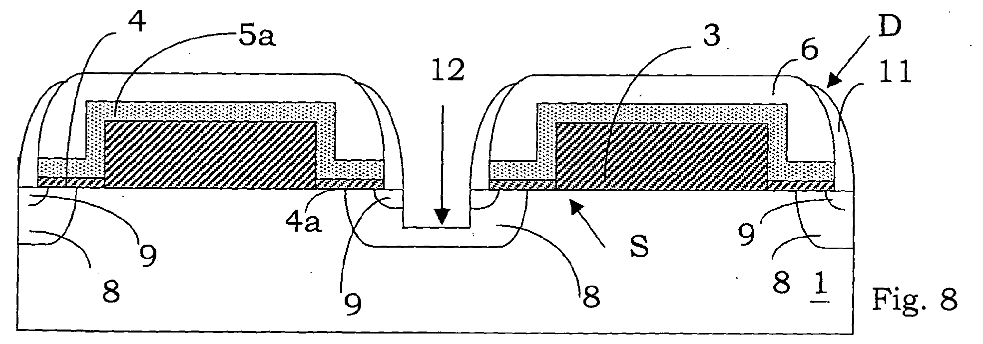
- Figures 1 to 8 show schematical views in vertical section and in enlarged scale respectively of a vertical-type MOS device undergoing different steps of a first embodiment of the manufacturing method according to the invention;
- Figures 9 to 12 show schematical views in vertical section and in enlarged scale respectively of a MOS device undergoing different steps of a second embodiment of the manufacturing method according to the invention.
- With reference to these drawings, a MOS transistor electronic device, in particular of the VDMOS type, manufactured according to the method of the present invention, is globally and schematically indicated with D.
- The process steps and the structures described hereinafter do not form a complete process flow for manufacturing integrated circuits. In fact, the present invention can be implemented together with the integrated circuit manufacturing techniques presently used in this field and only those commonly used process steps which are necessary to understand the invention are described hereinafter.
- The figures representing cross sections of device portions during the manufacturing are not drawn to scale, but they are drawn instead in order to show the important features of the invention.
- With reference to figure 7, a transistor device D formed on a
semiconductor material substrate 1 is shown. In particular, the device D can be a power device formed in the MOS technology with acentral gate electrode 5a andrespective source regions 9 located on opposite sides with respect to thegate electrode 5a. - These
source regions 9 are completely comprised inrespective body regions 8. - The
gate electrode 5a is formed above a channel region 1a formed in thesemiconductor substrate 1 and insulated from the latter by interposing a gate dielectric layer S. - According to the invention, this gate dielectric layer S comprises a first
dielectric portion 3 of a first thickness and a seconddielectric portion 4a of a second thickness. In other words, the gate dielectric layer S has a double thickness. - In particular, the first
dielectric portion 3 has a higher thickness than the seconddielectric portion 4a. Moreover, the firstdielectric portion 3 and the seconddielectric portion 4a are auto-aligned with each other. - The
second portion 4a is also aligned with thegate electrode 5a in correspondence with thesource 9 and channel 1a regions. - The
whole gate electrode 5a is covered on top by adielectric layer 6. The device D is then completed byspacers 11 formed on the side walls of theelectrode 5a and on thedielectric layer 6. - Advantageously, a
soft trench 12 is formed in thesubstrate 1 aligned withspacers 11. - The device D is then traditionally completed by forming a drain electrode behind the
substrate 1, not shown in the drawings. - With reference to figure 11, a second embodiment of the device D according to the invention is described.
- In this embodiment, the
gate electrode 5a is not present on the upper surface of the firstdielectric portion 3, but it is present only on the side walls of this firstdielectric portion 3. -
First spacers 14 are then formed on thegate electrode 5a. The device D is then completed bysecond spacers 11 formed on the side walls of theelectrode 5a and they cover at least partially thefirst spacers 14. Thesesecond spacers 11 are formed in adielectric layer 10 covering the top of both thegate electrode 5a and the firstdielectric portions 3. - In this embodiment too, advantageously, a
soft trench 12 is formed in thesubstrate 1 aligned with thesecond spacers 11. - A first embodiment of the manufacturing method of the device D according to the invention is now described.
- Convenient edge terminals, not shown in the figures, are traditionally formed on a
semiconductor substrate 1. - A thin dielectric layer, for example thermal oxide with a thickness being lower or equal to 100 nm, can be formed on the
semiconductor substrate 1, not shown in the figures. - According to the invention, a thick gate
dielectric layer 2 is formed on thesubstrate 1, for example through CVD (Chemical Vapor Deposition) deposition. - The thick
dielectric layer 2 is for example a USG (Undoped Silicon Glass), PSG (Phospho-Silicate Glass), BPSG (Boro-Phospho-Silicate Glass), TEOS (Tetraethyl Ortosilicate), SOG (Spin on Glass), silicon nitride layer, or a multilayer comprising a sequence of these layers. - Advantageously, the thickness of this
dielectric layer 2 ranges from 100 to 1000 nm. - A thermal densifying process of the thick
dielectric layer 2 is then advantageously performed. - As shown in figure 1, through a traditional photolithographic technique, a first plurality of
dielectric portions 3 is defined from the thickdielectric layer 2. - Advantageously, the etching step of this thick
dielectric layer 2 is performed through a unidirectional etching with final end point on thesemiconductor substrate 1. - Advantageously, a cleaning step is performed on the whole semiconductor device to prepare the manufacture of a second dielectric layer.
- A thin gate
dielectric layer 4 is then formed on the whole substrate in the regions not covered by thefirst portions 3. For example this thin gatedielectric layer 4 is formed through thermal oxidation or it can be formed by means of an oxinitride layer or an oxide/nitride/oxide multilayer. Advantageously, the thickness of the thin gatedielectric layer 4 is lower or equal to 100 nm. - A
conductive layer 5 is then formed on the whole device to manufacture gate electrodes as shown in figure 3. For example, a doped polysilicon layer, or a double polysilicon/metallic silicide layer is deposited. The thickness of thisconductive layer 5 is compatible with the planar geometries and the auto-alignment requirements of the manufacturing process. - A
further dielectric layer 6 is formed on the whole device for example through CVD (Chemical Vapor Deposition) deposition. - The
dielectric layer 6 is for example a low-conformality dielectric layer or multilayer like for example USG (Undoped-Silicate Glass), PSG (Phospho-Silicate Glass), TEOS (Tetraethyl Orthosilicate) formed through convenient deposition techniques. The thickness of thisdielectric layer 6 depends on the planar geometry and the project channel length. - Advantageously, having the dielectric layer 6 a low conformality, the thickness of this
dielectric layer 6 in correspondence with thethin layer 4 is lower than the layer formed in correspondence with theportions 3 of thethick dielectric layer 2, as shown in figure 3. - An etching step of the
dielectric layer 6 is then performed. For example this etching step is of the unidirectional type, with end point on theconductive layer 5.First spacers 7 are formed therefore on theconductive layer 5 in correspondence with the side walls of theportions 3, as shown in figure 4. - Advantageously, this
dielectric layer 6, after the etching step, covers also a portion of theconductive layer 5 located in correspondence with the upper surface of thefirst portions 3, while it is completely removed from further portions of theconductive layer 5 located in correspondence with thethin dielectric layer 4 being uncovered by thefirst spacers 7. - An etching step of the
conductive layer 5 being uncovered by thefirst spacers 7 is then performed. Aportion 5a of theconductive layer 5 which is therefore defined between thesespacers 7 and the substrate forms the gate electrode of the final device, as shown in figure 4. - Advantageously, this etching step is of the unidirectional type and it is timed or end point performed on the thin
gate dielectric layer 4. - Second
dielectric portions 4a of the thinggate dielectric layer 4 are then defined and comprised between thegate electrode 5a and thesemiconductor substrate 1, as shown in figure 5. - The first
dielectric portions 3 and the seconddielectric portions 4a form the gate dielectric layer S of the final device D. - A
body region 8 is then formed for example by performing a ionic implant in thesubstrate 1 and further diffusing said implantedregion 8. - Advantageously, an etching step of the residual thin
gate dielectric layer 4 is then performed up to uncover thesubstrate 1. This etching step is for example of the dry type and timed. - A
source region 9 is then formed, for example by performing a further ionic implant F in thesubstrate 1, as shown in figure 5. - A
further dielectric layer 10 is formed, on the whole device, for example through CVD (Chemical Vapor Deposition) deposition, as shown in figure 6. - The
dielectric layer 10 is for example a low-conformality dielectric layer or multilayer, like for example USG (Undoped-Silicate Glass), PSG (Phospho-Silicate Glass), TEOS (Tetraethyl Orthosilicate) formed through convenient deposition techniques. - The thickness of this
dielectric layer 10 depends on the planar geometry of the device D. - A diffusion step of the
source region 9 and a densifying step of thelast dielectric layer 10 are then performed, as shown in figure 6. - An etching step of this
last dielectric layer 10 is then performed to formsecond spacers 11. This etching step is for example of the unidirectional type with final end point on the semiconductor substrate, as shown in figure 7. - An advantageous embodiment of the device according to the invention provides the formation of a body/ source contact
soft trench 12 which is auto-aligned with thesecond spacers 11. - The presence of a soft trench in the source/body diffusion region allows a metalization contact to be formed on both source and body wells being extended on the whole active cell perimeter. Therefore, it avoids a previous photolithographic step to be performed, which selects the active cell area fraction being concerned by the source implant. Therefore the periphery of said channel region, which will obviously be equal to the perimeter of the gate electrode, is maximised.
- Finally, a strengthening of the device with respect to the destructive triggering of parasite elements in the active area is basically obtained.
- The device D according to the invention is then completed with traditional process steps providing:
- pad contact photolithography;
- front device metalization;
- preparation and metalization of the back wafer to form the device drain region.
- This first embodiment allows a device D to be obtained with low resistance of the
gate electrode 5a, covering completely thefirst portions 3. - A second embodiment of the manufacturing method of the device D according to the invention is now described.
- In particular the process steps up to the deposition of the
conductive layer 5 on the whole semiconductor substrate are the same as in the previous embodiment. - A
first dielectric layer 13 is then formed on theconductive layer 5, for example through CVD deposition, as shown in figure 9. - The
first dielectric layer 13 is for example a high-conformality dielectric layer or multilayer like for example USG (Undoped-Silicate Glass), PSG (Phospho-Silicate Glass), TEOS (Tetraethyl Orthosilicate) formed through convenient deposition techniques. The thickness of thisdielectric layer 13 depends on the planar geometry and the project channel length. - Having the first dielectric layer 13 a high conformality, the thickness of this layer is uniform on the whole device D.
- An etching step, for example unidirectional, of the first dielectric layer 13is performed at end point on the
conductive layer 5 to form afirst spacer 14, as shown in figure 10. - This etching step is then followed by an etching step, for example unidirectional, of the gate electrode (multi)layer, timed or with end point on the thin
gate dielectric layer 4. - The process flow is completed as in the previous embodiment starting from the deposition of the
dielectric layer 10 to formsecond spacers 11. - In particular, in this embodiment the
dielectric layer 10 is not removed from the upper surface of the firstdielectric portion 3 and it covers the top of both thegate electrode 5a and the firstdielectric portions 3. - Advantageously, in this second embodiment the removal of the gate electrode overlapped to the
thick dielectric portions 3 ensures a better gate/source side insulation quality because of the higher usable thickness of thesecond dielectric layer 10. - The present invention applies to VDMOS power devices of both types of polarity with any edge terminal structure and with cell in active area of any shape and size.
- The method according to the invention can be advantageously applied to signal VDMOS, IGBT and VDMOSFET devices, both of the P- and of the N- type.
- Both embodiments described can be also used to define photolithographically active area contacts, i.e. without auto-aligned formation of the second spacer. Obviously in this case size limits of the width of the device D or elementary cell are largely imposed by the definition and alignment specifications of the photoexposure equipment used. Nevertheless, an evident advantage mainly in the second embodiment, wherein the gate electrode overlapped to the
thick dielectric portion 3 also called intercell is removed, is the higher insulation quality between gate electrode and source region because of, as already mentioned, the higherdielectric layer 10 thickness which can be used in this embodiment. - In conclusion, by manufacturing a device D, with a gate dielectric layer S comprising two
portions - In particular, the removal of the photolithographic definition step of the gate electrode is allowed by exploiting the low conformality of the CVD
silicon oxide layer 4, for example USG, connected in turn to thethick dielectric layer 2 height and to the width of the device D or active cell (aspect ratio). - Moreover the self-alignment of the pattern of the gate electrode and mainly of the source and body region diffusions makes the definition of the photolithography itself forming initial thick
dielectric layer portions 3 less critical.
Claims (11)
- A manufacturing method for a power device (D) integrated on a semiconductor substrate (1) with double thickness of a gate dielectric layer (S) comprising the following steps:forming first dielectric portions (3) having a first thickness;forming on whole said semiconductor substrate (1) a first dielectric layer (4) thinner than said first dielectric portions (3);forming a conductive layer (5) on said first dielectric layer (4);forming a second dielectric layer (6, 13) on said conductive layer (5);.performing an etching step of said second dielectric layer (6, 13) and of said conductive layer (5) to form first spacers (7, 14) and a gate electrode (5a), to define, between said gate electrode (5a) and said substrate (1), second dielectric portions (4a) in said first dielectric layer (4), said second dielectric portions (4a) being auto-aligned with said first portions (3).
- A manufacturing method according to claim 1, characterised in that said second dielectric layer (6) is formed in a non conforming manner.
- A manufacturing method according to claim 2, characterised in that said etching step leaves portions of said second dielectric layer (6) to cover the top of said gate electrode (5a).
- A manufacturing method according to claim 1, characterised in that said second dielectric layer (13) is formed in a conforming manner.
- A manufacturing method according to claim 4, characterised in that said etching step removes said second dielectric layer (13) and said conductive layer (5) in correspondence with said first portions (3).
- A manufacturing method according to claim 3, characterised in that it further comprises the steps of:depositing a third dielectric layer (10) on whole said semiconductor substrate (1).
- A manufacturing method according to claim 6, characterised in that it further comprises the steps of:etching said third dielectric layer (10) in order to form second spacers (11) on the side walls of said gate electrode (5a) and on said first spacers (7, 14) and to leave said second dielectric layer (6) to cover the top of said gate electrode (5a).
- A manufacturing method according to claim 5, characterised in that it further comprises the steps of:depositing a third dielectric layer (10) on whole said semiconductor substrate (1).
- A manufacturing method according to claim 8, characterised in that it further comprises the steps of:etching said third dielectric layer (10) in order to form second spacers (11) on the side walls of said gate electrode (5a) and on said first spacers (7, 14) and to leave said third dielectric layer (10) to cover the top of said gate electrode (5a) and of said first dielectric portions (3).
- A manufacturing method according to claim 7 or 9, characterised in that it comprises the step of forming a soft trench (12) in the semiconductor substrate (1) being aligned with said second spacers (11).
- A power device (D) integrated on a semiconductor substrate (1) comprising a gate electrode (5a) formed above a channel region (1a) formed in said semiconductor substrate (1) and insulated from the latter by means of a gate dielectric layer (S) characterised in that said gate dielectric layer (S) comprises at least a first dielectric portion (3) having a first thickness and a second dielectric portion (4a) having a second thickness being lower than the first one, said first dielectric portion (3) and second dielectric portion (4a) being auto-aligned with each other.
Priority Applications (3)
| Application Number | Priority Date | Filing Date | Title |
|---|---|---|---|
| DE60332341T DE60332341D1 (en) | 2003-07-31 | 2003-07-31 | Method for producing an MIS power semiconductor device |
| EP03425526A EP1503423B1 (en) | 2003-07-31 | 2003-07-31 | Method of making a MIS power semiconductor device |
| US10/901,920 US7344966B2 (en) | 2003-07-31 | 2004-07-29 | Manufacturing method for a power device having an auto-aligned double thickness gate layer and corresponding device |
Applications Claiming Priority (1)
| Application Number | Priority Date | Filing Date | Title |
|---|---|---|---|
| EP03425526A EP1503423B1 (en) | 2003-07-31 | 2003-07-31 | Method of making a MIS power semiconductor device |
Publications (2)
| Publication Number | Publication Date |
|---|---|
| EP1503423A1 true EP1503423A1 (en) | 2005-02-02 |
| EP1503423B1 EP1503423B1 (en) | 2010-04-28 |
Family
ID=33522520
Family Applications (1)
| Application Number | Title | Priority Date | Filing Date |
|---|---|---|---|
| EP03425526A Expired - Lifetime EP1503423B1 (en) | 2003-07-31 | 2003-07-31 | Method of making a MIS power semiconductor device |
Country Status (3)
| Country | Link |
|---|---|
| US (1) | US7344966B2 (en) |
| EP (1) | EP1503423B1 (en) |
| DE (1) | DE60332341D1 (en) |
Cited By (1)
| Publication number | Priority date | Publication date | Assignee | Title |
|---|---|---|---|---|
| EP1918986A2 (en) * | 2006-11-02 | 2008-05-07 | STMicroelectronics S.r.l. | MOS Device resistant to ionizing radiatiion |
Families Citing this family (2)
| Publication number | Priority date | Publication date | Assignee | Title |
|---|---|---|---|---|
| US20110040697A1 (en) * | 2009-08-14 | 2011-02-17 | Oracle International Corporation | Reassignment and reconciliation for multi-dimensional sales territories |
| US8067283B2 (en) * | 2009-11-13 | 2011-11-29 | Vanguard International Semiconductor Corporation | Semiconductor device fabricating method |
Citations (1)
| Publication number | Priority date | Publication date | Assignee | Title |
|---|---|---|---|---|
| US20020140042A1 (en) * | 2001-03-28 | 2002-10-03 | International Rectifier Corporation | Ultra low QGD power MOSFET |
Family Cites Families (6)
| Publication number | Priority date | Publication date | Assignee | Title |
|---|---|---|---|---|
| US5895955A (en) * | 1997-01-10 | 1999-04-20 | Advanced Micro Devices, Inc. | MOS transistor employing a removable, dual layer etch stop to protect implant regions from sidewall spacer overetch |
| US6261978B1 (en) * | 1999-02-22 | 2001-07-17 | Motorola, Inc. | Process for forming semiconductor device with thick and thin films |
| JP2001351989A (en) * | 2000-06-05 | 2001-12-21 | Nec Corp | Method for manufacturing semiconductor device |
| JP3534056B2 (en) * | 2000-08-31 | 2004-06-07 | 日産自動車株式会社 | Method for manufacturing silicon carbide semiconductor device |
| DE60131094D1 (en) * | 2001-12-20 | 2007-12-06 | St Microelectronics Srl | Method for integrating metal oxide semiconductor field effect transistors |
| KR100440263B1 (en) * | 2002-10-29 | 2004-07-15 | 주식회사 하이닉스반도체 | Transistor in a semiconductor device and a method of manufacturing the same |
-
2003
- 2003-07-31 EP EP03425526A patent/EP1503423B1/en not_active Expired - Lifetime
- 2003-07-31 DE DE60332341T patent/DE60332341D1/en not_active Expired - Fee Related
-
2004
- 2004-07-29 US US10/901,920 patent/US7344966B2/en not_active Expired - Lifetime
Patent Citations (1)
| Publication number | Priority date | Publication date | Assignee | Title |
|---|---|---|---|---|
| US20020140042A1 (en) * | 2001-03-28 | 2002-10-03 | International Rectifier Corporation | Ultra low QGD power MOSFET |
Cited By (3)
| Publication number | Priority date | Publication date | Assignee | Title |
|---|---|---|---|---|
| EP1918986A2 (en) * | 2006-11-02 | 2008-05-07 | STMicroelectronics S.r.l. | MOS Device resistant to ionizing radiatiion |
| US8187943B2 (en) | 2006-11-02 | 2012-05-29 | Stmicroelectronics S.R.L. | MOS device resistant to ionizing radiation |
| US8471330B2 (en) | 2006-11-02 | 2013-06-25 | Stmicroelectronics S.R.L. | MOS device resistant to ionizing radiation |
Also Published As
| Publication number | Publication date |
|---|---|
| US7344966B2 (en) | 2008-03-18 |
| DE60332341D1 (en) | 2010-06-10 |
| EP1503423B1 (en) | 2010-04-28 |
| US20050059195A1 (en) | 2005-03-17 |
Similar Documents
| Publication | Publication Date | Title |
|---|---|---|
| US6638798B2 (en) | Method of fabricating a semiconductor device of high-voltage CMOS structure | |
| KR100271955B1 (en) | Semiconductor integrated circuit device | |
| US6815769B2 (en) | Power semiconductor component, IGBT and field-effect transistor | |
| US5355008A (en) | Diamond shaped gate mesh for cellular MOS transistor array | |
| KR100759939B1 (en) | Trench MOSF devices and methods of forming such devices | |
| US8785987B2 (en) | IGFET device having an RF capability | |
| US4890142A (en) | Power MOS transistor structure | |
| US6833586B2 (en) | LDMOS transistor with high voltage source and drain terminals | |
| US7187041B2 (en) | Vertical gate semiconductor device and method for fabricating the same | |
| US20040140527A1 (en) | Semiconductor device having poly-poly capacitor | |
| US6303961B1 (en) | Complementary semiconductor devices | |
| CN101211849B (en) | Semiconductor device capacitance preparation method | |
| JPH08241985A (en) | LD-MOS transistor | |
| CN1034841C (en) | Transistor with common base region | |
| US6605841B2 (en) | Method for producing an electrode by means of a field effect controllable semiconductor component and field-effect-controllable semiconductor component | |
| US8324669B2 (en) | Process for manufacturing a MOS device with intercell ion implant confined to the gate electrode region | |
| EP1503423B1 (en) | Method of making a MIS power semiconductor device | |
| US20200411510A1 (en) | Multi-finger devices with reduced parasitic capacitance | |
| EP1535342A1 (en) | Method of making a vertical gate semiconductor device | |
| JP2712359B2 (en) | Method for manufacturing semiconductor device | |
| CN112234094B (en) | Metal oxide semiconductor device and method for manufacturing the same | |
| CN110010685A (en) | Groove metal-oxide-semiconductor element and its manufacturing method | |
| CN111326581B (en) | Gate drive integrated circuit and forming method thereof | |
| KR100577447B1 (en) | Semiconductor device having a shared gate electrode and fabrication thereof | |
| CN120980917A (en) | semiconductor devices |
Legal Events
| Date | Code | Title | Description |
|---|---|---|---|
| PUAI | Public reference made under article 153(3) epc to a published international application that has entered the european phase |
Free format text: ORIGINAL CODE: 0009012 |
|
| AK | Designated contracting states |
Kind code of ref document: A1 Designated state(s): AT BE BG CH CY CZ DE DK EE ES FI FR GB GR HU IE IT LI LU MC NL PT RO SE SI SK TR |
|
| AX | Request for extension of the european patent |
Extension state: AL LT LV MK |
|
| 17P | Request for examination filed |
Effective date: 20050721 |
|
| AKX | Designation fees paid |
Designated state(s): DE FR GB IT |
|
| 17Q | First examination report despatched |
Effective date: 20090310 |
|
| RTI1 | Title (correction) |
Free format text: METHOD OF MAKING A MIS POWER SEMICONDUCTOR DEVICE |
|
| GRAP | Despatch of communication of intention to grant a patent |
Free format text: ORIGINAL CODE: EPIDOSNIGR1 |
|
| GRAS | Grant fee paid |
Free format text: ORIGINAL CODE: EPIDOSNIGR3 |
|
| GRAA | (expected) grant |
Free format text: ORIGINAL CODE: 0009210 |
|
| RAP1 | Party data changed (applicant data changed or rights of an application transferred) |
Owner name: STMICROELECTRONICS SRL |
|
| AK | Designated contracting states |
Kind code of ref document: B1 Designated state(s): DE FR GB IT |
|
| REG | Reference to a national code |
Ref country code: GB Ref legal event code: FG4D |
|
| REF | Corresponds to: |
Ref document number: 60332341 Country of ref document: DE Date of ref document: 20100610 Kind code of ref document: P |
|
| PLBE | No opposition filed within time limit |
Free format text: ORIGINAL CODE: 0009261 |
|
| STAA | Information on the status of an ep patent application or granted ep patent |
Free format text: STATUS: NO OPPOSITION FILED WITHIN TIME LIMIT |
|
| GBPC | Gb: european patent ceased through non-payment of renewal fee |
Effective date: 20100731 |
|
| 26N | No opposition filed |
Effective date: 20110131 |
|
| PG25 | Lapsed in a contracting state [announced via postgrant information from national office to epo] |
Ref country code: DE Free format text: LAPSE BECAUSE OF NON-PAYMENT OF DUE FEES Effective date: 20110201 |
|
| REG | Reference to a national code |
Ref country code: DE Ref legal event code: R119 Ref document number: 60332341 Country of ref document: DE Effective date: 20110201 |
|
| PG25 | Lapsed in a contracting state [announced via postgrant information from national office to epo] |
Ref country code: GB Free format text: LAPSE BECAUSE OF NON-PAYMENT OF DUE FEES Effective date: 20100731 |
|
| PGFP | Annual fee paid to national office [announced via postgrant information from national office to epo] |
Ref country code: IT Payment date: 20120626 Year of fee payment: 10 |
|
| PGFP | Annual fee paid to national office [announced via postgrant information from national office to epo] |
Ref country code: FR Payment date: 20120806 Year of fee payment: 10 |
|
| REG | Reference to a national code |
Ref country code: FR Ref legal event code: ST Effective date: 20140331 |
|
| PG25 | Lapsed in a contracting state [announced via postgrant information from national office to epo] |
Ref country code: IT Free format text: LAPSE BECAUSE OF NON-PAYMENT OF DUE FEES Effective date: 20130731 Ref country code: FR Free format text: LAPSE BECAUSE OF NON-PAYMENT OF DUE FEES Effective date: 20130731 |