BACKGROUND OF THE INVENTION
-
The present invention relates to a fixing device that fixes an unfixed
toner image formed on a sheet medium. The fixing device comprises: a
heating roller; a pressing roller that is pressed against the heating roller; a belt
that moves by being wound around an outer periphery of the pressing roller
and nipped between the pressing roller and the heating roller; and a belt
stretcher over which the belt is stretched. The present invention also relates
to an image forming apparatus incorporating such a fixing device.
-
An image forming apparatus such as a copying machine, a printer
and a facsimile machine incorporates a heating roller type fixing device in
which an unfixed toner on a recording medium is subjected to a press contact
with heat to thereby fix the unfixed toner on the recording medium. Such a
fixing device comprises: a rotatable heating roller coated with an elastic body
on the surface thereof and housing a heat source therein; a belt stretched over
plural supporting rollers, and a pressing member for forming a nip region by
causing the belt to wind around the heating roller by a predetermined angle
while causing the elastic body on the surface of the heating roller to undergo
deformation by locally applying a larger pressure to the exit of the nip region
than the other portions, thereby making it easier for a sheet medium to be
discharged from the nip portion. Such a configuration is disclosed in
Japanese Patent No. 3084692.
-
In the fixing device, the surface of the heating roller has been
deformed in advance due to the presence of the pressing member, and the
deformation on the surface is relieved momentarily while toner is in contact
with the surface of the heating roller. For this reason, when a sheet medium
is discharged from the nip portion, an contact force between the toner and the
heating roller is reduced in inhibiting the sheet medium from winding around
the heating roller, so that even a recording sheet of paper that is not very firm
can be readily separated at the exit of the belt nip. This device thus
eliminates the need for a separating claw member.
-
However, plural supporting rollers and the rotation bearings are
required. Further, not only the peripheral length of the belt is extended, but
also the fixing device becomes complex with an increase in both size and cost.
The structure such that makes the fixing device complex with an increase in
size and cost naturally makes the image forming apparatus equipped with such
a fixing device complex with an increase in size and cost.
-
Moreover, the belt is heated at the nip portion with the rotatable
heating roller housing the heat source; however, with the configuration in which
the belt is stretched over plural rollers and its peripheral length is inevitably
extended, heat energy is absorbed by plural supporting rollers when it moves
along a predetermined path. In addition, natural heat release is increased
with the peripheral length. This extends a time needed to reach a
predetermined temperature, which in turn extends a so-called warm-up time
needed for the fixing operation to be enabled since the apparatus has been
activated. Hence, this configuration is not preferable.
-
Further, the configuration, in which deformation of the elastic layer on
the heating roller is caused by winding the belt around the heating roller by an
angle needed to form the nip and by applying a larger pressure locally at the
exit of the nip portion than the other portions, is suitable in inhibiting a sheet
medium from winding around the heating roller, however, the sheet medium
discharged along the deformation of the elastic layer is distorted, by being
curled along the deformation or wrinkled as a result of a local high pressure.
-
Japanese Patent Publication No. 6-40235B discloses a fixing device
in which an unfixed toner image is fixed on a recording medium by passing
through a nip region formed between roller members which are in press
contact with each other. In this device, the rotating speed of the roller
members can be set to either a first speed or a second speed in accordance
with the characteristic of the recording medium.
-
However, since the heat capacity of the roller members are large, the
warm-up time is extended. Moreover, the recording medium passing through
the nip region formed by deforming the roller members with a pressure
undergoes distortion, such as curls and wrinkles, because an applied stress
induced by this pressure is large.
-
Japanese Patent Publication No. 8-262903A discloses a fixing device
in which an endless belt stretched over a heating roller, which is coated with an
elastic body on the surface thereof and housing a heat source therein, is run
while being in contact with the heating roller, and a non-rotatable pressing pad
provided on the inner side of the endless belt to press the endless belt against
the heating roller, not only forms a nip portion, but also causes the elastic layer
on the surface of the heating roller to undergo deformation. A sheet medium
bearing an unfixed toner image is forced to pass through a space between the
heating roller and the endless belt for the toner to be fixed on the sheet
medium. Since the pressing pad is not rotated, heat transmitted from the
heating roller is hardly dissipated. Therefore it has an advantage that a
quantity of heat absorbed from the heating roller is small.
-
Nevertheless, the warm-up time is extended because heat is
transmitted to the pressing pad from the heating roller via the endless belt
during the warm-up operation. In addition, three or more rollers are
necessary to circulate the belt, which raises another problem that the device is
increased in size.
SUMMARY OF THE INVENTION
-
It is therefore an object of the invention to provide a heating roller type
fixing device which is simple, compact and cost-saving in the structure, and
which is capable of shortening a warm-up time as well as suppressing the
distortion of a discharged sheet medium (recording medium), such as the
occurrence of curls and wrinkles, by reducing a stress applied to the sheet
medium.
-
In order to achieve the above object, according to the invention, there
is provided a fixing device for fixing an unfixed toner image formed on a
sheet-shaped recording medium, comprising:
- a first roller, incorporating a heat source therein;
- a second roller, being pressed toward the first roller;
- an endless belt, a part of which is wound on an outer periphery of the
second roller to be circulated; and
- a non-rotatable belt stretcher, which stretches the endless belt
together with the second roller such that the circulated endless belt is slid on a
first face extending in a widthwise direction of the endless belt, and such that a
tensile force is applied to both widthwise end portions of the endless belt,
wherein:
- the circulated endless belt is nipped between the first roller and the
second roller to form a first nip portion through which the unfixed toner image
is fixed on the recording medium with heat from the heat source; and
- the first face of the belt stretcher is curved in the widthwise direction
of the endless belt.
-
-
Here, a widthwise center portion of the first face of the belt stretcher is
made concave or convex from the both widthwise end portions thereof.
-
Preferably, the circulated endless belt is nipped between the first
roller and the belt stretcher to form a second nip portion through which the
unfixed toner image is fixed on the recording medium with heat from the heat
source.
-
With the above configurations, since the both widthwise end portions
of the endless belt are brought into close contact with the first face of the belt
stretcher, the buckling of the endless belt at the second nip portion can be
avoided. In addition, the total nipping length for the recording medium can be
elongated to realize the stable fixing operation.
-
Here, it is preferable that the belt stretcher comprises a wall member
having a second face adjacent to at least one of the both widthwise end
portions of the endless belt, in order to restrict a wobbling motion of the
circulated endless belt.
-
It is further preferable that the wall member is integrally formed with
the belt stretcher. More preferably, the wall member is monolithically formed
with the belt stretcher.
-
With the above configuration, the wobbling motion of the circulated
endless belt can be eliminated so that the stable fixing operation can be
realized.
-
It is also preferable that the second face of the wall member is
continuously extended from the first face of the belt stretcher.
-
Here, it is further preferable that the second face of the wall member
and the first face of the belt stretcher facing one of the widthwise end portions
of the endless belt form a first angle. A side end face of the endless belt and
the first face of the belt stretcher facing one of the widthwise end portions of
the endless belt form a second angle which is smaller than the first angle.
-
With the above configurations, the bucking of the widthwise end
portion of the circulated endless belt can be avoided more effectively.
-
It is also preferable that a height dimension of the wall member is
larger than a thickness dimension of the endless belt.
-
It is also preferable that the wall member is formed with a chamfered
face continued to the second face to guide the circulated endless belt into the
first face of the belt stretcher.
-
With the above configurations, the circulated endless belt can be
prevented from surmounting the wall member.
-
It is also preferable that a part of the wall member is abutted against
the first roller to define a gap between the first roller and the first face of the
belt stretcher at the second nip portion.
-
Here, it is further preferable that a distance between the first roller
and the first face of the belt stretcher at the gap is larger than a thickness
dimension of the endless belt. The distance is determined such that the first
face of the belt stretcher presses the recording medium against the first roller
through the endless belt when the recording medium enters the second nip
portion.
-
With the above configurations, since the gap serves as a heat
insulation layer during the warm-up operation of the apparatus, a heat quantity
absorbed from the first roller (i.e., heat loss) via the endless belt is lessened,
so that the time period required for the warm-up operation can be shortened.
When the recording medium enters the second nip portion, the gap is
eliminated so that the stable contact between the recording medium and the
first roller can be realized.
-
Preferably, wherein the belt stretcher is pivotable. More preferably,
an elastic member urges the belt stretcher toward the first roller. Here, a pivot
center of the belt stretcher may be identical with or different from a rotational
axis of the second roller.
-
Preferably, the belt stretcher has a semiannular or circular cross
section viewed from the widthwise direction of the endless belt.
-
In a case where an open side of the semiannular cross section is
faced the second roller, the belt stretcher can be disposed as close as possible
to the second roller. Therefore, the entire length of the endless belt can be
shortened, so that the natural heat release for prolonging the warm-up
operation can be suppressed. In addition, the fixing device can be made
compact.
-
Preferably, a cleaner is disposed between the second roller and the
belt stretcher so as to abut against an inner peripheral face of the endless belt.
-
Preferably, the belt stretcher is disposed at an upstream side or a
downstream side in the circulating direction of the endless belt relative to the
first nip portion.
-
According to the invention, there is also provided an image forming
apparatus, comprising:
- an image forming device, which forms a toner image on a recording
medium; and
- the above-described fixing device for fixing the toner image on the
recording medium.
-
BRIEF DESCRIPTION OF THE DRAWINGS
-
The above objects and advantages of the present invention will
become more apparent by describing in detail preferred exemplary
embodiments thereof with reference to the accompanying drawings, wherein:
- Fig. 1A is a section view of a fixing device according to a first
embodiment of the invention;
- Fig. 1 B is a partial section view taken along a line IB-IB of Fig. 1A;
- Fig. 2 is a partial section view taken along a line II-II of Fig. 1A;
- Fig. 3 is a partial section view of a press contact portion of a belt
stretcher and a heating roller in the fixing device of Fig. 1A, showing a state
that a heat-resistant belt is removed;
- Fig. 4 is a partial section view of the press contact portion, showing a
state that the heat-resistant belt is attached;
- Fig. 5 is a partial section view of the press contact portion, showing a
state that a sheet medium enters the press contact portion;
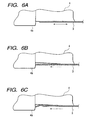
- Fig. 6A is an enlarged schematic view for explaining the movement of
the belt sliding on the belt stretcher;
- Figs. 6B and 6C are enlarged schematic views of a belt stretcher
according to a first comparative example, showing a case that buckling occurs
at the side edge of the belt;
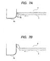
- Fig. 7A is an enlarged schematic views of a belt stretcher and a belt
according to a second comparative example;
- Fig. 7B is an enlarged schematic views of a belt stretcher and a belt
according to a third comparative example;
- Figs. 8A and 8B are enlarged schematic views of the shapes of the
belt stretcher in the fixing device of Fig. 1A;
- Fig. 8C is an enlarged schematic view of a side edge face of the belt
and a protruding wall of the belt stretcher in the fixing device of Fig. 1A;
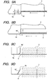
- Fig. 9A is an enlarged schematic view showing a relationship between
the thickness of the belt and the height of the protruding wall;
- Fig. 9B is an enlarged schematic view showing a function of a
chamfered portion formed on the protruding wall;
- Fig. 9C is a plan view of the belt and the protruding wall viewed from
the lower side of Fig. 9B;
- Fig. 9D is a plan view of a modified example of the protruding wall of
Fig. 9C;
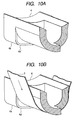
- Fig. 10A is a perspective view of the protruding wall of Fig. 9B,
showing a state that the belt is removed;
- Fig. 10B is a perspective view of the protruding wall of Fig. 9B,
showing a state that the belt is attached;
- Fig. 11A is a graph showing fixing pressure variation generated by the
belt stretcher in a case where a spring for assisting a pivot movement of the
belt stretcher is not provided;
- Fig. 11 B is a graph showing fixing pressure variation generated by the
belt stretcher in a case where the spring for assisting the pivot movement of
the belt stretcher is provided;
- Fig. 12A is a section view of a fixing device according to a second
embodiment of the invention;
- Fig. 12B is a partial section view taken along a line XIIB-XIIB of Fig.
12A;
- Fig. 13 is a section view of a fixing device according to a third
embodiment of the invention;
- Fig. 14A is a section view of a fixing device according to a fourth
embodiment of the invention;
- Fig. 14B is a partial section view taken along a line XIVB-XIVB of Fig.
14A;
- Fig. 15A is a partial section view of a press contact portion of a belt
stretcher and a heating roller in the fixing device of Fig. 14A, showing a state
before a sheet medium enters the press contact portion;
- Fig. 15B is a partial section view taken along a line XVB-XVB of Fig.
15A;
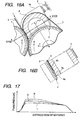
- Fig. 16A is a partial section view of the press contact portion, showing
a state that the sheet medium is discharged from the press contact portion;
- Fig. 16B is a partial section view taken along a line XVIB-XVIB of Fig.
16A;
- Fig. 17 is a graph showing fixing pressure variation generated by the
belt stretcher of Fig. 14A in a case where a spring for assisting the pivot
movement of the belt stretcher is provided;
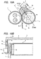
- Fig. 18A is a section view of a fixing device according to a fifth
embodiment of the invention;
- Fig. 18B is a partial section view taken along a fine XVIIIB-XVIIIB of
Fig. 18A; and
- Fig. 19 is a schematic section view of an image forming apparatus
incorporating any one of the fixing devices.
-
DETAILED DESCRIPTION OF THE INVENTION
-
Embodiments of the invention will now be described with reference to
the accompanying drawings.
-
Fig. 1A shows a fixing device according to a first embodiment of the
invention. A heating roller 1 is formed by coating the periphery of a base
member 1 b, which is a pipe member having an outer diameter of about 25 mm
and a thickness of about 0.7 mm, with an elastic body 1 c having a thickness of
about 0.4 mm. The heating roller 1 is rotatable in the direction indicated by an
arrow Q and includes two column-shaped halogen lamps 1 a of 1050 W in the
interior of the base member 1b as a heat source. A pressing roller 2 is formed
by coating the periphery of a base member 2b, which is a pipe member having
an outer diameter of about 25 mm and a thickness of about 0.7 mm, with the
elastic body 2c having a thickness of about 0.2 mm. The pressing roller 2 is
configured to achieve a press-contact force F between the heating roller 1 and
the pressing roller 2 at 10 kg or below and the nip length of about 10 mm, and
is rotatable in the direction indicated by an arrow R.
-
A heat-resistant belt 3 (hereinafter, simply referred as "belt") is an
endless belt made movable by being nipped between the heating roller 1 and
the pressing roller 2 and stretched over the pressing roller 2 and a belt
stretcher 4 along their peripheries. The belt 3 is formed from a metal tube,
such as a stainless tube and a nickel electrocast tube, or a tube of
heat-resistant resin, such as polyimide and silicon, having a thickness of 0.03
mm or greater.
-
According to this embodiment, because the outer diameters of the
heating roller 1 and the pressing roller 2 are set to a diameter as small as 25
mm, a sheet medium 5 having been subjected to the fixing operation winds
around neither the heating roller 1 nor the belt 3, which eliminates the need for
a member for forcedly separating the sheet medium 5. Also, the rigidity is
enhanced by providing a PFA layer of about 30-µm-thick on the surface layer
of the elastic body 1c on the heating roller 1. Although the elastic bodies 1c
and 2c differ in thickness, they undergo elastic deformation almost identically,
and a so-called flat nip is formed. Hence, no difference is generated in
transportation speed of the belt 3 or a sheet medium 5 with respect to the
peripheral speed of the heating roller 1, which enables an image to be fixed in
an extremely stable manner.
-
In this embodiment, two heat sources 1 a are built into the heating
roller 1 such that the halogen lamps are placed in the different positions to be
selectively activated, it becomes easier to control temperatures under different
positions or conditions, that is, between a portion where the belt 3 winds
around the heating roller 1 and a portion where the belt stretcher 4 comes in
sliding contact with the heating roller 1, and between a wide sheet medium and
a narrow sheet medium.
-
The belt stretcher 4 is provided upstream of the nip portion between
the heating roller 1 and the pressing roller 2 in the transportation direction of
the sheet medium 5, and is provided to be able to pivot in a direction indicated
by an arrow P about the rotary shaft 2a of the pressing roller 2. The belt
stretcher 4 is configured in such a manner that the belt 3 is stretched over in
the tangential direction to the heating roller 1 while no sheet medium 5 is
passing through the nip portion. When a fixing pressure is too large at the
position from which a sheet medium 5 starts to enter the nip portion, the sheet
medium 5 is not able to enter the nip portion smoothly, and the fixing may be
performed while the leading end of the sheet medium 5 being folded.
However, by configuring the belt 3 to be stretched over in the tangential
direction to the heating roller 1, it is possible to form an entrance portion
through which a sheet medium 5 is able to enter the nip portion smoothly and
stably.
-
The belt stretcher 4 is a semiannular member which is disposed in an
inner periphery of the heat-resistant so as to provide a tensile force f to the belt
in cooperation with the pressing roller 2. Accordingly, the belt 3 slides on the
semiannular member. The belt stretcher 4 is provided at a position where a
nip is formed by bringing the belt 3 into press contact with the heating roller 1
beyond a tangential line L of the press contact portion between the heating
roller 1 and the pressing roller 2.
-
A protruding wall 4a is formed to protrude from one end or both ends
of the belt stretcher 4, and regulates the leaning when the belt 3 leans to one
side as it abuts on the protruding wall 4a. A spring 9 is provided in a space
between the frame and the end face of the protruding wall 4a on the opposite
side of the heating roller 1. The belt stretcher 4 is thereby slightly pressed
against the heating roller 1 by the spring 9 and is positioned such that the belt
3 comes in sliding contact with the heating roller 1.
-
In order to drive the pressing roller 2 in a stable manner by stretching
the belt 3 over the pressing roller 2 and the belt stretcher 4, it is preferable to
set a frictional coefficient between the pressing roller 2 and the belt 3 larger
than a frictional coefficient between the belt stretcher 4 and the belt 3. The
frictional coefficient, however, may become unstable due to intrusion of foreign
substances or abrasion. In contrast, by setting a winding angle of the belt 3 to
the pressing roller 2 smaller than a winding angle of the belt 3 to the belt
stretcher 4, and by setting the diameter of the belt stretcher 4 smaller than the
diameter of the pressing roller 2, it is possible to shorten a distance over which
the belt 3 slides on the belt stretcher 4. Destabilizing factors derived from a
change with time or disturbances can be thus avoided, which in turn makes it
possible to drive the belt 3 in a stable manner by the pressing roller 2.
-
A cleaner 6 is provided somewhere between the pressing roller 2 and
the belt stretcher 4 to come in sliding contact with the inner peripheral surface
of the belt 3, and thereby cleans the foreign substances, abrasive powder, etc.
on the inner peripheral surface of the belt 3. By cleaning the foreign
substances, abrasive powder, etc., the belt 3 is refreshed and destabilizing
factors are thereby removed. In addition, a concave portion 4f provided in the
belt stretcher 4 is suitable to store the removed foreign substances, abrasive
powder, etc.
-
A nip entrance is defined as a position at which the belt stretcher 4 is
slightly pressed against the heating roller 1, and a nip exit is defined as a
position at which the pressing roller 2 is pressed against the heating roller 1.
A sheet medium 5 enters from the nip entrance and passes a space between
the belt 3 and the heating roller 1 so that an unfixed toner image 5a is fixed on
the sheet medium 5. The sheet medium 5 is then discharged from the nip exit
in the direction of the tangential line L.
-
A supporting structure of the pressing roller 2 and the belt stretcher 4
will now be described. The both ends of rotary shaft 2a of the pressing roller
2 are, as is shown in Fig. 1 B, supported by frames 7 on the right and left via
bearings 7a to be free to rotate (the right side is omitted from the drawing).
On the both sides of the rotary shaft 2a of the pressing roller 2 are fitted arms
4b to be free to pivot, and a guiding groove 4c is formed in each arm 4b so as
to face the belt stretcher 4. On the other hand, at the both ends of the belt
stretcher 4 are formed guiding portions 4d to be fitted into the guiding grooves
4c in the arms 4b via springs 4e. The belt stretcher 4 is therefore of a
structure such that provides the tensile force f to the belt 3 as it is pushed by
the springs 4e in a direction to move away from the pressing roller 2.
-
In this embodiment, the belt stretcher 4 is used as a non-rotating
member for the belt 3 to slide thereon, a bearing or the like is not necessary,
which can make the supporting structure simpler. In addition, by forming the
belt stretcher 4 in a semiannular shape, it is possible provide the belt stretcher
4 in the closest proximity to the pressing roller 2 by facing the missing half of
the ring toward the pressing roller 2. This also makes it possible to form the
belt 3 with a shorter peripheral length. It is thus possible to provide a compact,
inexpensive heating roller type fixing device by simplifying the structure.
-
Also, because the belt 3 moves along a path of the least necessary
length, for the belt 3 heated at the nip portion with the heating roller 1 housing
the heat source, heat energy absorbed while moving along a predetermined
path can be minimized. Also, because the peripheral length is short, a drop in
temperature due to natural heat release is small, which makes it possible to
shorten a so-called warm-up time needed to reach a desired temperature for
the fixing to be enabled since the apparatus has been activated.
-
Also, because the belt 3 is brought into press contact with the heating
roller 1 to form the nip portion with the tensile force f provided from the belt
stretcher 4 in cooperation with the pressing roller 2, the nip length can be
readily extended and the structure can be simplified, which in turn makes the
device compact and less expensive.
-
In order to fix an unfixed toner image 5a formed on a sheet medium 5
in a stable manner, it is essential to melt the unfixed toner image 5a sufficiently
before it is fixed, and predetermined temperature and melting time are needed.
In this embodiment, since there is no need to provide a member for extending
the nip length by causing the elastic body 1 c of the heating roller 1 to undergo
considerable deformation, the thickness of the elastic body 1 c can be made
thin. In addition, since there is no need to set a large press-contact pressure
to the pressing roller 2 in causing the elastic body to undergo deformation.
Hence, only a small stress is applied to the sheet medium 5 bearing the
unfixed toner image 5a when it passes through the space between the heating
roller 1 and the belt 3, which suppresses the sheet medium distortion, such as
the occurrence of wrinkles, when the sheet medium 5 is discharged after the
unfixed toner image 5a is fixed thereon.
-
Thus, not only can the need to increase the mechanical rigidity of the
heating roller type fixing device be eliminated, but also the heating roller 1 can
be thinner. It is thus possible to increase the heating speed with which the
heat source heats the belt 3. The pressing roller 2 can be thinner, too, and a
heat capacity can be smaller, which can reduce absorption of heat energy from
the belt 3. It is thus possible to shorten the warm-up time.
-
As shown in Figs. 2 and 3, the protruding wall 4a of the belt stretcher
4 is positioned by coming in sliding contact with the heating roller 1 on a
slide-contact surface 4g. A gap (step difference) G, which is larger than the
thickness of the belt 3, is provided to the belt stretcher 4 between the
slide-contact surface 4g and a pressing surface 4h that presses the belt 3 and
thereby presses a sheet medium 5 against the heating roller 1. The pressing
surface 4h is formed concentrically with the heating roller 1. To be more
concrete, by forming the gap G from a step difference of about 110 µm, and
forming the belt 3 to have a thickness of about 80 µm, a clearance of about 30
µm is secured, which enables the fixing to be performed in a stable manner
even for a sheet medium 5 as thick as 60 µm.
-
As shown in Fig. 4, the belt 3 is nipped between the heating roller 1
and the pressing roller 2, and is brought into press contact with the heating
roller by the belt stretcher 4 so as to define the nip entrance,
-
In is not practical to bring a speed in the process step of forming an
unfixed toner image 5a on a sheet medium 5, which is the preceding step of
the fixing step, into perfect agreement with a speed in the fixing step, when
irregularities in specifications of various mass-produced components are
concerned. Hence, speeds in the consecutive steps are balanced by setting
the speed in the fixing step to one side, that is, either reduced or increased
from the speed in the process step of forming an unfixed toner image 5a on a
sheet medium 5 in consideration of such irregularities. Although there is a
need to specify an entering speed of a sheet medium 5 by gripping the sheet
medium 5 in a reliable manner at the nip entrance, the need can be satisfied
by the configuration described above.
-
In addition, the surface of the elastic body 1c of the heating roller 1
and the surface of the belt 3 move at the same peripheral speed to fix an
unfixed toner image 5a formed on a sheet medium 5. However, when the
surface of the belt 3 is corrugated or the leading end of the sheet medium 5 is
corrugated, the initial condition of the fixing operation may become unstable.
Hence, by configuring the belt 3 in such a manner that it is pressed against the
heating roller 1 at the nip entrance, the both components are able to meet in a
stable condition, which enables the unfixed toner image 5a to be fixed in an
extremely stable manner.
-
In this embodiment, in the foregoing state while no sheet medium 5 is
passing through, the gap G is formed between the belt 3 and the belt stretcher
4. Hence, the clearance in the gap G serves as a heat insulation layer during
the warm-up. A heat quantity absorbed from the heating roller 1 via the belt 3
is thus lessened, and so is a heat loss. The warm-up time, therefore, can be
shortened.
-
On the other hand, when a sheet medium 5 is passing through the nip
portion, as is shown in Fig. 5, the protruding wall 4a of the belt stretcher 4 is
kept spaced apart from the heating roller 1, which eliminates the gap G
between the belt 3 and the belt stretcher 4. The sheet medium 5 is thus
pressed by the belt 3 at the nip portion, and hence pressed against the heating
roller 1, which makes it possible to achieve adequate fixing by adjusting this
pressing pressure to a desired pressure with the use of the spring 9 shown in
Fig. 1 A.
-
Also, a heat quantity, accumulated while the belt stretcher 4 is heated
by the heating roller 1, is small due to the presence of the gap G. Hence,
when the sheet medium 5 enters the nip portion, the second surface of the
sheet medium 5 opposite to the first surface on which the unfixed toner image
5a is formed cools the belt 3 having a small heat capacity. Since a heat
quantity supplied from the belt stretcher 4 side is small, in a case of
double-sided image fixing to fix an unfixed toner image 5a on the second
surface after the unfixed toner image 5a formed on the first surface of the
sheet medium 5 is fixed, the image fixed earlier on the first surface is not
excessively heated when the second surface undergoes fixing, and no
disturbance occurs in the image fixed on the first surface.
-
In this embodiment, as is shown in Fig. 1A, the spring 9 is provided
upstream of the press contact portion between the heating roller 1 and the
pressing roller 2 in the moving direction of the belt 3, at a position remote from
the pivot center of the belt stretcher 4. The belt 3 is driven by driving one of
the heating roller 1 and the pressing roller 2, and the belt stretcher 4 starts to
pivot toward the heating roller 1 by this driving force and the sliding-frictional
force between the belt 3 and the belt stretcher 4. However, there may be a
case where the pivotal moving force alone cannot induce a sufficient fixing
pressure to fix an unfixed toner image 5a formed on a sheet medium 5. To
address this inconvenience, the pivotal moving force is set to a desired fixing
pressure with the assistance of the spring 9, so that the unfixed toner image 5a
can be fixed in an extremely stable manner.
-
It is preferable that the tensile force f, applied to the belt 3 from the
belt stretcher 4 in cooperation with the pressing roller 2, is identical across the
entire stretched region. However, in some cases, the accuracy of
straightness of the pressing roller 2 and the belt stretcher 4, or the accuracy of
homogeneity of the inner periphery of the belt 3, or an erroneous factor of a
quantity of deformation occurred while the tensile force is applied to the
pressing roller 2 and the belt stretcher 4, makes it difficult to make the tensile
force f identical across the entire stretched region.
-
In addition, besides the foregoing state, as is shown in Fig. 6A, the
belt 3 runs with wobbling due to the factors, such as the accuracy of
parallelism in the pressing roller 2 and the belt stretcher 4 provided at their
respective positions, and the larger the frictional force between the inner
surface of the belt 3 and the pressing roller 2 as well as the belt stretcher 4, the
larger the wobble-leaning force becomes, which makes it difficult to regulate
the running position.
-
The condition to achieve the position regulation in preventing the
wobbling of the belt 3 is to provide a position regulator well capable of
responding to the wobble-leaning force of the belt 3 and to have a sufficient
withstanding strength while the position of the belt 3 is regulated by the
position regulator. Hence, it is crucial whether the belt 3 can secure the
withstanding strength.
-
As is shown in Fig. 1 B, by forming the belt stretcher 4 to be supported
at the both ends with the springs 4e in providing the tensile force f to the belt 3
at least at the side edges of the belt 3 in the width direction, and to have the
protruding wall 4a that protrudes from each tension applying portion and
regulates the side edge face of the belt 3, the belt 3 is brought into a close
contact state to the tension applying portion while running along the protruding
wall 4a.
-
For example, assume that, as is shown in Fig. 6B, a concave, a step
difference, a clearance or the like is present in the vicinity of the side edge of
the belt stretcher 4 provided with the protruding wall 4a. Then, the belt 3 is
not able to come in close contact to the sliding surface of the belt stretcher 4,
and a clearance is formed. Under these conditions, when the belt 3 runs with
wobbling and abuts on the protruding wall 4a, a larger wobble-leaning force is
exerted, upon which, as is shown in Fig. 6C, the bucking occurs at the side
edge of the belt 3.
-
When the inclined angle at the side edge face of the belt 3 and the
extending angle of the protruding wall 4a relative to the sliding surface of the
belt stretcher 4 are concerned, as is shown in Fig. 7A, in a case where the
inclined angle 2 of the side edge face of the belt 3 becomes larger than the
extending angle 1 of the protruding wall 4a, if the belt 3 runs with wobbling
and abuts on the protruding Wall 4a, a large wobble-leaning force is exerted,
upon which the side edge of the belt 3 is lifted along the protruding wall 4a as
indicated. On the other hand, as is shown in Fig. 7B, in a case where the
angle 2 at the side edge face of the belt 3 is smaller than the extending angle
1 of the protruding wall 4a and a clearance is formed between the sliding
surface of the belt stretcher 4 and the protruding wall 4a, if the belt 3 runs with
wobbling and abuts on the protruding wall 4a, a large wobble-leaning force is
exerted, upon which the side edge of the belt 3 engages in the clearance
portion along the protruding wall 4a, thereby giving rise to the bucking at the
side edge of the belt 3.
-
In order to prevent the occurrence of bucking at the side edge of the
belt 3, as is shown in Fig. 8B, the belt 3 needs to come in close contact to the
sliding surface of the belt stretcher 4 without any clearance at the side edge
region of the belt 3, and the protruding wall 4a needs to have a wall surface
that rises continuously from the sliding surface. The protruding wall 4a is
preferably provided as a monolithic part of the belt stretcher 4. Even when
the protruding wall 4a is an individual member from the belt stretcher 4, it is
preferable that the protruding wall 4a is provided integrally with the belt
stretcher 4, so that the belt 3 slides on the sliding surface of the belt stretcher 4
in close contact without leaving any clearance. To this end, it is also
preferable to support the belt stretcher 4 at the both ends with the use of the
springs 4e, so that when the belt 3 is stretched over, as is shown in Fig. 1 B,
the belt stretcher 4 is preferably shaped into an inversed crown shape in which
the sliding surface is concave from the both ends to the center portion.
-
In view of the foregoing, the side edge of the belt 3 abuts on the
protruding wall 4a while coming close contact with the sliding surface of the
belt stretcher 4, so that the wobbling of the belt 3 can be regulated effectively
and the position regulation of the belt 3 to be performed in a stable manner.
In this case, the belt 3 is supported by the belt stretcher 4 at the both side
edge regions thereof, thereby generating a bent at the center portion thereof.
In view of this, as shown in Fig. 8A, the sliding surface of the belt stretcher 4
may be shaped into a crown shape in which the sliding surface is convex from
the both ends to the center portion, under the condition that the side edge
regions of the belt 3 are brought into close contact with the sliding surface of
the belt stretcher 4 (along the reference line ).
-
Further, in order to prevent the bucking at the side edge of the belt 3,
as is shown in Fig. 8C, it is preferable to make the inclined angle 2 of the side
edge face of the belt 3 less than the extending angle 1 of the protruding wall
4a relative to the sliding surface of the belt stretcher (the reference line ), that
is, to set as 2 ≤ 1.
-
As a structure such that applies a tensile force f to the belt 3 from the
belt stretcher 4 in cooperation with the pressing roller 2, by forming the
protruding wall 4a on either the pressing roller 2 or the belt stretcher 4 side, the
wobbling side edge of the belt 3 abuts on the protruding wall 4a, thereby the
wobbling regulation is performed. However, in a case where the protruding
wall 4a is provided on the pressing roller 2, it is necessary to provide a
structure for receiving the protruding wall 4a on the heating roller 1 which is
brought into press contact with the pressing roller 2. Such a provision may be
a limitation or a restriction to the design of the heating roller 1. In a case
where the protruding wall 4a is provided in the belt stretcher 4 as in this
embodiment, the heating roller can be made free from such a design limitation.
-
Also, the belt 3 closely adheres to the belt stretcher 4 and runs with
sliding due to the tensile force f, at the portion where it abuts on the protruding
wall 4a and the position regulation on the running with wobbling is thereby
effected. When the tensile force f is greater than the running force with
wobbling, there may occur a phenomenon that the side edge of the belt 3
surmounts the protruding wall 4a or the end face of the belt 3 extends to
overlap a part of the protruding wall 4a. In order to avoid such phenomena
while increasing the degree of the design freedom, such as the edge strength
of the belt 3, the tensile force f, the running force with wobbling of the belt 3, it
is preferable to form the protruding wall 4a, as is shown in Fig. 9A, to have a
belt regulating height h at least twice the thickness t of the belt 3.
-
When the belt 3 is brought into close contact with the sliding surface
of the belt stretcher 4, the belt 3 tends to wobble. Therefore, it is necessary to
provide a structure for smoothly subjecting the belt 3 having been separated
from the pressing roller 2 to the wobbling regulation by the protruding wall 4a
of the belt stretcher 4. In this embodiment, as shown in Figs. 9B, 9C, 10A and
10B, a chamfered portion 4a' is formed along an inner top edge of the
protruding wall 4a' to smoothly introduce the belt 3 to the region where the
protruding wall 4a is formed. As shown in Fig. 9A, the belt regulating height h
is defined so as to exclude the chamfered portion 4a'.
-
Alternatively, as shown in Fig. 9D, the chamfered portion 4a' may be
formed at the entrance of the region where the protruding wall 4a is formed
such that the width of the sliding surface of the belt stretcher 4 is gradually
reduced.
-
In this embodiment, the spring 9 is provided upstream of the press
contact portion between the heating roller 1 and the pressing roller 2 in the
moving direction of the belt 3, which is remote from the pivot center of the belt
stretcher 4. Hence, as is shown in Fig. 11 B, it is possible to increase the
fixing pressure continuously from the nip entrance toward the press contact
portion between the heating roller 1 and the pressing roller 2 due to the
mechanism of leverage, and a stress having an inflection point is not applied to
a sheet medium 5. Hence, no fixing irregularities or the like are generated in
a fixed image, which not only enables an unfixed toner image 5a to be fixed in
an extremely stable manner, but also the sheet medium distortion, such as the
occurrence of wrinkles, can be suppressed for a sheet medium 5 discharged
after the unfixed toner image 5a is fixed.
-
Incidentally, "H" denotes the case of a thick sheet medium or a
layered sheet medium such as an envelop, having a large heat capacity, or a
transparent sheet medium such as an OHP sheet, "S" denotes the case of a
standard sheet medium, and "L" denotes a thin sheet medium or a sheet
medium having a poor heat resistance.
-
For the comparison purpose, Fig. 11A shows the pressing pressure
variation in a case where the spring 9 is not provided. In other words, it is a
case where the fixing pressure is generated only by the pivot movement of the
belt stretcher 4 without the assistance of the spring 9.
-
The fixing pressure (abutting pressure distribution) between the
heating roller 1 and the belt 3 reaches the maximum pressure at a portion at
which the heating roller 1 and the pressing roller 2 come in pressing contact
with each other. In a case where it is difficult to melt an unfixed toner image
5a sufficiently to enable the fixing in a stable manner, for example, when the
surface of a sheet medium 5 is irregular, or the surface is made of a material
having excellent hermeticity and is so smooth that a melted toner image hardly
permeates inside like an OHP sheet, by providing a higher pressure than that
in the melting stage to melted toner in the final stage where the sheet medium
5 passes through the nip, not only can the surface of the melted toner be
smooth, but also the permeation into the sheet medium 5 can be promoted and
the fixed image, therefore, can be more stable.
-
Figs. 12A and 12B show a fixing device according to a second
embodiment of the invention. Members similar to those in the first
embodiment are designated by the same reference numerals and the repetitive
explanations for those will be omitted.
-
In the first embodiment, the belt stretcher 4 is allowed to pivot by a
predetermined angle about the common axis with the rotary shaft 2a of the
pressing roller 2. In this embodiment, the belt stretcher 4 is configured so as
to be allowed to pivot by a predetermined angle about an axis 7b, which is
different from the rotary shaft 2a of the pressing roller 2.
-
In other words, on the both sides of the axis 7b provided at a position
different from the axial center of the rotary shaft 2a are fitted arms 4b to be free
to pivot, and a guiding groove 4c is formed in each arm 4b so as to face the
belt stretcher 4. On the other hand, at the both ends of the belt stretcher 4
are formed guiding portions 4d to be fitted into the guiding grooves 4c in the
arms 4b via springs 4e. The belt stretcher 4 is therefore of a structure such
that provides a tensile force f to the belt 3 as it is pushed by the springs 4e in a
direction to move away from the pressing roller 2.
-
This configuration can change the torque acting on the belt stretcher
4 (in this embodiment, the torque is increased), which makes it possible to
adjust the press-contact force between the belt 3 and the heating roller 1 in
accordance with the position of the axis 7b. Also in this embodiment, as is
shown in Fig. 2, a gap (step difference) G, which is larger than the thickness of
the belt 3 is provided to the belt stretcher 4 between the slide-contact surface
4g and the pressing surface 4h that presses the belt 3 to press a sheet
medium 5 against the heating roller 1.
-
Fig. 13 shows a fixing device according to a third embodiment of the
invention. Members similar to those in the first embodiment are designated
by the same reference numerals and the repetitive explanations for those will
be omitted.
-
In this embodiment, the belt stretcher 4 is provided as a non-rotatable
cylindrical member. Also in this embodiment, as is shown in Fig. 2, a gap
(step difference) G, which is larger than the thickness of the belt 3, is provided
to the belt stretcher 4 between the slide-contact surface 4g and the pressing
surface 4h that presses the belt 3 to press the sheet medium 5 against the
heating roller 1.
-
A fourth embodiment of the invention will be described with reference
to Figs. 14A through 17. Members similar to those in the first embodiment are
designated by the same reference numerals and the repetitive explanations for
those will be omitted.
-
In this embodiment, the belt stretcher 4 is provided downstream of the
press contact portion between the heating roller 1 and the pressing roller 2 in
the transportation direction of a sheet medium 5, and is allowed to pivot in the
direction indicated by an arrow P about the rotary shaft 2a of the pressing roller
2, as shown in Figs. 14A and 14b.
-
The belt stretcher 4 is a semiannular member which is disposed in an
inner periphery of the heat-resistant so as to provide a tensile force f to the belt
in cooperation with the pressing roller 2. Accordingly, the belt 3 slides on the
semiannular member.
-
An entrance of the fixing nip is defined as a position at which the belt
stretcher 4 is slightly pressed against the heating roller 1, and an exit of the
fixing nip is defined as a position at which the belt stretcher 4 is separated from
the heating roller 1. A sheet medium 5 enters from the nip entrance and
passes a space between the belt 3 and the heating roller 1 so that an unfixed
toner image 5a is fixed on the sheet medium 5. The sheet medium 5 is then
discharged from the nip exit in the direction of the tangential line L.
-
As is shown in Figs. 15A and 15B, the protruding wall 4a of the belt
stretcher 4 is positioned by coming in sliding contact with the heating roller 1
on a slide-contact surface 4g. A gap (step difference) G, which is larger than
the thickness of the belt 3, is provided to the belt stretcher 4 between the
slide-contact surface 4g and a pressing surface 4h that presses the belt 3 and
thereby presses a sheet medium 5 against the heating roller 1. The pressing
surface 4h is formed concentrically with the heating roller 1. To be more
concrete, by forming the gap G from a step difference of about 110 µm, and
forming the belt 3 to have a thickness of about 80 µm, a clearance of about 30
µm is secured, which enables the fixing to be performed in a stable manner
even for a sheet medium 5 as thick as 60 µm.
-
The belt 3 is nipped between the heating roller 1 and the pressing
roller 2, and is brought into press contact with the heating roller 1 by the belt
stretcher 4 at the exit of the nip region.
-
In this embodiment, in the foregoing state while no sheet medium 5 is
passing through, the gap G is formed between the belt 3 and the belt stretcher
4. Hence, the clearance in the gap G serves as a heat insulation layer during
the warm-up. A heat quantity absorbed from the heating roller 1 via the belt 3
is thus lessened, and so is a heat loss. The warm-up time, therefore, can be
shortened.
-
On the other hand, when a sheet medium 5 is passing through the
fixing nip portion, as is shown in Figs. 16A and 16B, the protruding wall 4a of
the belt stretcher 4 is kept spaced apart from the heating roller 1, which
eliminates the gap G between the belt 3 and the belt stretcher 4. The sheet
medium 5 is thereby pressed by the belt 3 at the fixing nip portion, and hence
pressed against the heating roller 1, which makes it possible to achieve
adequate fixing by adjusting this pressing force to a desired pressure with the
use of the spring 9 shown in Fig. 14A.
-
Also, a heat quantity, accumulated while the belt stretcher 4 is heated
by the heating roller 1, is small due to the presence of the gap G. Hence,
when the sheet medium 5 enters the nip portion, the second surface of the
sheet medium 5 opposite to the first surface on which the unfixed toner image
5a is formed cools the belt 3 having a small heat capacity. Since a heat
quantity supplied from the belt stretcher 4 side is small, in a case of
double-sided image fixing to fix an unfixed toner image 5a on the second
surface after the unfixed toner image 5a formed on the first surface of the
sheet medium 5 is fixed, the image fixed earlier on the first surface is not
excessively heated when the second surface undergoes fixing, and no
disturbance occurs in the image fixed on the first surface.
-
The belt 3 is driven when either the heating roller 1 and the pressing
roller 2 is driven, and the belt stretcher 4 starts to pivot in a direction to move
away from the heating roller 1 by this driving force and the sliding-frictional
force between the belt 3 and the belt stretcher 4. However, by setting a
desired fixing pressure by pushing the belt stretcher 4 toward the heating roller
1 by a desired pushing force larger than the pivotal moving force, it is possible
to fix an unfixed toner image 5a in an extremely stable manner.
-
Hence, in this embodiment, the spring 9 is provided downstream of
the press contact portion between the heating roller 1 and the pressing roller 2
in the moving direction of the belt 3, which is remote from the pivot center of
the belt stretcher 4.
-
In this embodiment, the spring 9 is provided downstream of the press
contact portion between the heating roller 1 and the pressing roller 2 in the
moving direction of the belt 3, which is remote from the pivot center of the belt
stretcher 4. Hence, as is shown in Fig. 17, it is possible to increase the fixing
pressure continuously from the nip entrance toward the press contact portion
between the heating roller 1 and the pressing roller 2 due to the mechanism of
leverage, and a stress having an inflection point is not applied to a sheet
medium 5. Hence, no fixing irregularities or the like are generated in a fixed
image, which not only enables an unfixed toner image 5a to be fixed in an
extremely stable manner, but also the sheet medium distortion, such as the
occurrence of wrinkles, can be suppressed for a sheet medium 5 discharged
after the unfixed toner image 5a is fixed.
-
Incidentally, "H" denotes the case of a thick sheet medium or a
layered sheet medium such as an envelop, having a large heat capacity, or a
transparent sheet medium such as an OHP sheet, "S" denotes the case of a
standard sheet medium, and "L" denotes a thin sheet medium or a sheet
medium having a poor heat resistance.
-
Figs. 18A and 18B show a fixing device according to a fifth
embodiment of the invention. Members similar to those in the fourth
embodiment are designated by the same reference numerals and the repetitive
explanations for those will be omitted.
-
In the fourth embodiment, the belt stretcher 4 is allowed to pivot by a
predetermined angle about the common axis with the rotary shaft 2a of the
pressing roller 2. In this embodiment, the belt stretcher 4 is configured so as
to be allowed to pivot by a predetermined angle about an axis 7b, which is
different from the rotary shaft 2a of the pressing roller 2.
-
In other words, on the both sides of the axis 7b provided at a position
different from the axial center of the rotary shaft 2a are fitted arms 4b to be free
to pivot, and a guiding groove 4c is formed in each arm 4b so as to face the
belt stretcher 4. On the other hand, at the both ends of the belt stretcher 4
are formed guiding portions 4d to be fitted into the guiding grooves 4c in the
arms 4b via springs 4e. The belt stretcher 4 is therefore of a structure such
that provides a tensile force f to the belt 3 as it is pushed by the springs 4e in a
direction to move away from the pressing roller 2.
-
This configuration can change the torque acting on the belt stretcher
4 (in this embodiment, the torque is increased), which makes it possible to
adjust the press-contact force between the belt 3 and the heating roller 1 in
accordance with the position of the axis 7b.
-
In the above embodiments, the heating roller 1 or the pressing roller 2
serves as the driving roller. In this case, in order to achieve the safe driving, it
is preferable to use either roller whichever is the harder as the driving roller
and the other softer roller as the driven roller. The belt 3 is wound around the
pressing roller 2 to be circulated, and is brought into press contact with the
elastic body 1 c coated on the surface of the heating roller 1. In this case,
since the pressing roller 2 serves as the driving roller and the heating roller 1
serves as the driven roller, the pressing roller 2 determines the transportation
speed of the belt 3, that is, of a sheet medium 5 bearing an unfixed toner
image 5a. The pressing roller 2 is configured to have a harder surface than at
least the elastic body 1 c. This configuration enables the driving with a stable
transportation speed to be achieved without causing distortion.
-
In the above embodiments, the rotational speed of the heating roller 1
and the pressing roller 2 may be selectably controlled. The control of the
driving speed will now be described. A driving member has two rotational
speeds to drive the heating roller 1 and the pressing roller 2, and drives the
heating roller 1 and the pressing roller 2 selectively at a first rotational speed or
a second rotational speed slower than the first rotational speed, according to
the sheet medium properties.
-
In order to set the rotational speed, a detector for detecting the sheet
medium properties is provided, and a table or the like for selecting the
rotational speed corresponding to the sheet medium properties is also
provided. The sheet medium properties are detected while a sheet medium 5
bearing an unfixed toner image 5a is being transported, and the rotational
speed is selected according to the detected sheet medium properties through
the table when the fixing command is processed.
-
To select the rotational speed, the members interlocked with the fixing
device may be manually operated before the fixing command is processed, or
remotely controlled by an electrical signal or the like.
-
The sheet medium 5 bearing the unfixed toner image 5a must be
used in diversified purposes, including a typical sheet medium of paper or the
like, a thick sheet medium having a large heat capacity, a transparent sheet
medium (OHP sheet), etc. In comparison with a typical sheet medium, for a
thick sheet medium and a layered sheet medium, such as an envelope, having
a large heat capacity, a transparent sheet medium (OHP sheet medium), etc.,
a relatively long time period is needed to melt the unfixed toner image 5a
sufficiently before it is fixed thereon. In such a case, by selectively driving the
heating roller 1 and the pressing roller 2 at the first rotational speed or the
second rotational speed slower than the first rotational speed according to the
sheet medium properties, the unfixed toner image 5a is melted adequately,
and the fixing as desired can be achieved.
-
In addition, even by the selective driving at the first rotational speed or
the second rotational speed, a stress, applied to a sheet medium 5 bearing an
unfixed toner image 5a when the sheet medium 5 passes through a space
between the heating roller 1 and the belt 3, varies little and remains small.
This suppresses the sheet medium distortion, such as the occurrence of the
wrinkles, for the sheet medium 5 discharged after the unfixed toner image 5a is
fixed thereon. Hence, not only can the need to increase the mechanical
rigidity of the heating roller type fixing apparatus be eliminated, but also the
heating roller 1 can be thinner. A heating speed with which the heat source
heats the belt 3 can be thus increased. In addition, because the pressing
roller 2 can be thinner, too, a heat capacity can be smaller. Heat energy
absorbed from the belt 3 is thus lessened, which makes it possible to shorten a
so-called warm-up time needed to reach a predetermined temperature for the
fixing to be enabled since the apparatus has been activated. The selective
driving may be realized by, for example, selectively changing the rotational
speed of a driving motor.
-
Fig. 19 shows an image forming apparatus 10 incorporating any one
of the fixing devices as described the above.
-
The image forming apparatus 10 includes a housing 10a, a medium
discharging tray 10c formed on the top portion of the housing 10a, and a door
cover 10b attached at the front of the housing 10a to be free to open and close.
Inside the housing 10a are provided an exposure unit W, an image formation
unit D, a transfer belt unit 29 having an image transporter 18, and a medium
feeding unit 30. In the vicinity of the door 10b is provided a medium
transportation unit 11. Each unit is detachably loaded inside the housing 10a,
so that any one of the units can be individually detached from the housing 10a
during a maintenance work or the like for repairing or replacement.
-
The image formation unit D includes plural (four, in the embodiment)
image forming stations Y (for yellow), M (for magenta), C (for cyan), and K (for
black), each forming an image of a different color. Each of the image forming
stations Y, M, C, and K includes an image carrier 17 comprising a
photosensitive drum, as well as a charger 19 comprising a corona charger and
a development device 20 both provided in the periphery of the image carrier 17.
The respective image forming stations Y, M, C, and K are provided in parallel
below the transfer belt unit 29 along an arch-shaped line with the image
carriers 17 facing upward. The placement order of the respective image
forming stations Y, M, C, and K is arbitrary.
-
The transfer belt unit 29 includes a driving roller 12 driven to rotate by
an illustrated driving source provided at the lower end of the housing 10a, a
driven roller 13 provided diagonally above the driving roller 12, a tension roller
14, the image transporter 18 comprising an intermediate transfer belt stretched
over these three rollers or at least two of them and driven to circulate in a
direction indicated by an arrow S, and a cleaner 15 that abuts on the surface of
the image transporter 18. The driven roller 13, the tension roller 14, and the
image transporter 18 are arranged such that the circulating path of the image
transporter 18 extends obliquely. More specifically, they are arranged such
that a belt surface 18a faced down in the belt transportation direction is
positioned lower and a belt surface 18b faced up in the belt transportation
direction is positioned upper.
-
Thus, the image forming stations Y, M, C, and K are arrayed obliquely.
The belt surface 18a of the image transporter 18 comes in contact with the
image carriers 17 along the arch-shaped line, and the image carriers 17 are
then driven to rotate in the transportation direction of the image transporter 18
as indicated by arrows. The flexible image transporter 18 in the shape of an
endless sleeve comes in contact with the image carriers 17 at almost the same
winding angle to cover the image carriers 17 from above. This configuration
makes it possible to adjust a press-contact pressure or a nip width between the
image carriers 17 and the image transporter 18 by controlling a tensile force
applied to the image transporter 18 from the tension roller 14, placement
intervals of the image carriers 17, the winding angle (the curvature of the arch),
etc.
-
The driving roller 12 also serves as a back-up roller of a secondary
transfer roller 39. On the peripheral surface of the driving roller 12 is formed a
rubber layer having, for example, a thickness of about 3 mm and a volume
resistivity of 105 Ωcm or less, and the grounding via a metal shaft is used as an
electrical conduction path of the secondary bias provided via the secondary
transfer roller 39. In this manner, by providing the driving roller 12 with the
rubber layer having high friction and impact absorbing ability, an impact when a
sheet medium enters the secondary transfer portion is hardly transmitted to the
image transporter 18, which makes is possible to prevent deterioration of the
image quality, In addition, by making the diameter of the driving roller 12
smaller than the diameters of the driven roller 13 and the back-up roller 14, a
sheet medium, having undergone the secondary transfer, can be separated
more readily by its own elastic force. Further, the driven roller 13 is used also
as a back-up roller of the cleaner 15 described below.
-
Alternatively, the inclined direction of the circulating path of the image
transporter 18 is arbitrary and the array of the image forming stations Y, M, C,
K is determined accordingly.
-
The cleaner 15 is provided on the side of the belt surface 18a faced
down in the transportation direction, and is provided with a cleaning blade 15a
that removes toner remaining on the surface of the image transporter 18 after
the secondary transfer, and a toner transporter 15b that transports collected
toner. The cleaning blade 15a abuts on the image transporter 18 at the
winding portion of the image transporter 18 to the driven roller 13. On the
back side of the image transporter 18 abuts a primary transfer member 16
oppositely to the image carriers 17 of the respective image forming stations Y,
M, C, and K described below, and the transfer bias is thus applied to the
primary transfer portion 16.
-
The exposing unit W is provided in a space below the image
formation unit D obliquely arrayed. Also, the medium feeding unit 30 is
provided at the bottom of the housing 10a below the exposing unit W. The
exposing unit W is accommodated in the case entirely, and the case is
provided in a space formed diagonally below the belt surface 18a faced down
in the transportation direction. At the bottom of the case are provided
horizontally a single scanner 21 comprising a polygonal mirror motor 21 a, a
polygonal mirror (rotary multi-faceted mirror) 21 b. In an optical system B,
which reflects laser beams from plural laser light sources 23 modulated by
image signals of their respective colors on the polygonal mirror 21 b to be
deflected and scanned on the respective image carriers 17, are provided a
single f- lens 22 and plural reflection mirrors 24 that return scanning light
paths of respective colors to the corresponding image carriers 17 not in parallel
with each other.
-
In the exposing unit W configured as described above, image signals,
corresponding to respective colors, from the polygonal mirror 21 b are emitted
in the form of laser beams formed and modulated according to the common
data clock frequency, and irradiated to the image carriers 17 in the respective
image forming stations Y, M, C, and K by way of the f- lens 22 and the
reflection mirrors 24 for a latent image to be formed. The scanning light path
is bent by providing the reflection mirrors 24, and the height of the case can be
thereby lowered, which in turn makes it possible to achieve a compact optical
system.
-
Moreover, the reflection mirrors 24 are set so that the lengths of the
scanning light paths to the image carriers 17 in the respective image forming
stations Y, M, C, and K are all equal. By configuring in such a manner that
the lengths of light paths (light path lengths) to the respective image carriers 17
from the polygonal mirror 21 b in the exposing unit W become nearly equal with
respect to the image formation unit D, the scanning widths of light beams
scanned via the respective light paths also become nearly equal. This
eliminates the need for a special configuration to form image signals. Hence,
the laser light source is modulated by different image signals for images of
different colors; nevertheless, it can be modulated according to the common
data clock frequency, and because the common reflection surface is used,
color shifting induced from a relative difference in the sub-scanning directions
can be prevented. It is thus possible to fabricate an inexpensive color image
forming apparatus with a simple structure.
-
Further, in this apparatus, by providing the scanning optical system on
the lower side of the apparatus, it is possible to minimize vibrations of the
scanning optical system induced by vibrations given to the frame supporting
the image forming apparatus from the driving system in the apparatus, which
can in turn prevent deterioration of the image quality. In particular, by
providing the scanner 21 at the bottom of the case, vibrations given to the
entire housing 10a from the polygonal motor 21 a per se can be minimized, and
deterioration of the image quality can be prevented. Also, by limiting the
number of the polygonal motor 21 a, serving as the vibration source, to one,
vibrations given to the entire case can be minimized.
-
The medium feeding unit 30 is provided with a cassette tray 35 in
which a pile of sheet media are held, and a pick-up roller 36 that feeds the
sheet media from the feed cassette 35 one by one. The medium
transportation unit 11 is provided with a pair of gate rollers 37 that regulates
the feed timing of a sheet medium to the secondary transfer portion (one of the
rollers is provided on the housing 10a side), the secondary transfer roller 39
that is brought into pressing contact with the driving roller 12 and the image
transporter 18, a main transportation path 38, a fixing unit 40, a pair of
discharging rollers 41, and a double-sided printing transportation path 42.
-
An unfixed toner image secondarily transferred on a sheet medium is
fixed at the nip portion formed by the fixing unit 40 at a predetermined
temperature. In this embodiment, it is possible to provide the fixing unit 40 in
a space formed diagonally above the belt surface 18b of the transfer belt,
which is faced up in the transportation direction, in other words, a space on the
opposite side of the image forming stations Y, M, C, and K, with respect to the
transfer belt. This configuration can reduce heat to be transmitted to the
exposing unit W, the image transporter 18, and the image forming means, and
the frequency of a color-shift correcting operation for respective colors can be
reduced. In particular, the exposing unit W is at the remotest position from
the fixing unit 40, and distortion caused by heat in the scanning optical system
components can be minimized, which can in turn prevent a shift in color.
-
In this embodiment, because the image transporter 18 is extended
diagonally, a wide space can be secured on the right side of the drawing for
providing the fixing unit 40. Hence, not only can the apparatus be made
compact, but also transmission of heat, generated in the fixing unit 40, to the
exposure unit W, the image transporter 18, and the respective image forming
stations Y, M, C, and K, all positioned on the left side of the drawing, can be
prevented. Also, because the exposure unit W can be provided in a space on
the lower left of the image formation unit D, vibrations of the scanning optical
system in the exposure unit W, induced by vibrations given to the housing 10a
from the driving system in the image formation unit D, can be minimized, which
can in turn prevent the deterioration of the image quality.
-
Because no cleaner is provided, the corona charger 19 is adopted as
the charger. In a case where the charger comprises a roller, primary transfer
residual toner present on the image carrier 17 accumulates on the roller, albeit
in a slight quantity, and gives rise to a charging defect. However, toner hardly
adheres to the corona charger 19, which is non-contact charger. The
occurrence of a charging defect, therefore, can be prevented.
-
In this apparatus, the intermediate transfer belt serves as the image
transporter 18 and is configured to come in contact with the image carriers 17.
However, the image transporter 18 may be a sheet medium transportation belt
that attracts a sheet medium on the surface and moves to transport the sheet
medium in transferring toner images sequentially to be superposed on the
surface of the sheet medium, and is configured to come in contact with the
image carriers 17. In this case, the belt transportation direction of the sheet
medium transportation belt serving as the image transporter 18 is made
upward on the lower surface that comes in contact with the image carriers 17.
-
It should be appreciated that the invention is not limited to the above
embodiments, and can be modified in various manners. For example,
although a tandem-type color image forming apparatus in which the
development devices of respective colors are arrayed has been described the
above, the invention can be applied to a rotary-type color image forming
apparatus, in which the development devices of respective colors are mounted
to the rotary frame, as well as to a monochrome image forming apparatus.