EP1502901A1 - Method of forming split phase area inside glass - Google Patents
Method of forming split phase area inside glass Download PDFInfo
- Publication number
- EP1502901A1 EP1502901A1 EP03717659A EP03717659A EP1502901A1 EP 1502901 A1 EP1502901 A1 EP 1502901A1 EP 03717659 A EP03717659 A EP 03717659A EP 03717659 A EP03717659 A EP 03717659A EP 1502901 A1 EP1502901 A1 EP 1502901A1
- Authority
- EP
- European Patent Office
- Prior art keywords
- phase separation
- glass
- laser
- separation region
- phase
- Prior art date
- Legal status (The legal status is an assumption and is not a legal conclusion. Google has not performed a legal analysis and makes no representation as to the accuracy of the status listed.)
- Withdrawn
Links
Images

Classifications
-
- C—CHEMISTRY; METALLURGY
- C03—GLASS; MINERAL OR SLAG WOOL
- C03C—CHEMICAL COMPOSITION OF GLASSES, GLAZES OR VITREOUS ENAMELS; SURFACE TREATMENT OF GLASS; SURFACE TREATMENT OF FIBRES OR FILAMENTS MADE FROM GLASS, MINERALS OR SLAGS; JOINING GLASS TO GLASS OR OTHER MATERIALS
- C03C23/00—Other surface treatment of glass not in the form of fibres or filaments
- C03C23/0005—Other surface treatment of glass not in the form of fibres or filaments by irradiation
- C03C23/0025—Other surface treatment of glass not in the form of fibres or filaments by irradiation by a laser beam
-
- C—CHEMISTRY; METALLURGY
- C03—GLASS; MINERAL OR SLAG WOOL
- C03C—CHEMICAL COMPOSITION OF GLASSES, GLAZES OR VITREOUS ENAMELS; SURFACE TREATMENT OF GLASS; SURFACE TREATMENT OF FIBRES OR FILAMENTS MADE FROM GLASS, MINERALS OR SLAGS; JOINING GLASS TO GLASS OR OTHER MATERIALS
- C03C10/00—Devitrified glass ceramics, i.e. glass ceramics having a crystalline phase dispersed in a glassy phase and constituting at least 50% by weight of the total composition
-
- C—CHEMISTRY; METALLURGY
- C03—GLASS; MINERAL OR SLAG WOOL
- C03C—CHEMICAL COMPOSITION OF GLASSES, GLAZES OR VITREOUS ENAMELS; SURFACE TREATMENT OF GLASS; SURFACE TREATMENT OF FIBRES OR FILAMENTS MADE FROM GLASS, MINERALS OR SLAGS; JOINING GLASS TO GLASS OR OTHER MATERIALS
- C03C10/00—Devitrified glass ceramics, i.e. glass ceramics having a crystalline phase dispersed in a glassy phase and constituting at least 50% by weight of the total composition
- C03C10/0009—Devitrified glass ceramics, i.e. glass ceramics having a crystalline phase dispersed in a glassy phase and constituting at least 50% by weight of the total composition containing silica as main constituent
-
- C—CHEMISTRY; METALLURGY
- C03—GLASS; MINERAL OR SLAG WOOL
- C03C—CHEMICAL COMPOSITION OF GLASSES, GLAZES OR VITREOUS ENAMELS; SURFACE TREATMENT OF GLASS; SURFACE TREATMENT OF FIBRES OR FILAMENTS MADE FROM GLASS, MINERALS OR SLAGS; JOINING GLASS TO GLASS OR OTHER MATERIALS
- C03C14/00—Glass compositions containing a non-glass component, e.g. compositions containing fibres, filaments, whiskers, platelets, or the like, dispersed in a glass matrix
- C03C14/006—Glass compositions containing a non-glass component, e.g. compositions containing fibres, filaments, whiskers, platelets, or the like, dispersed in a glass matrix the non-glass component being in the form of microcrystallites, e.g. of optically or electrically active material
-
- C—CHEMISTRY; METALLURGY
- C03—GLASS; MINERAL OR SLAG WOOL
- C03C—CHEMICAL COMPOSITION OF GLASSES, GLAZES OR VITREOUS ENAMELS; SURFACE TREATMENT OF GLASS; SURFACE TREATMENT OF FIBRES OR FILAMENTS MADE FROM GLASS, MINERALS OR SLAGS; JOINING GLASS TO GLASS OR OTHER MATERIALS
- C03C2214/00—Nature of the non-vitreous component
- C03C2214/16—Microcrystallites, e.g. of optically or electrically active material
Definitions
- the present invention relates to a method for forming a phase separation region in a glass by converging a laser pulse in a glass containing a metastable immiscible phase.
- Phase separation is a phenomenon in which a single-phase supercooled liquid separates into at least two liquid phases. Phase separation in a temperature range below a liquid phase temperature is called metastable immiscibility, and phase separation in a temperature range above the liquid phase temperature is called stable immiscibility.
- a "homogeneous glass containing a metastable immiscible phase” looks homogeneous as a glass (in a solid state), but potentially has a metastable immiscible phase.
- a single-phase glass In a glass containing a stable immiscibility region, the melt itself is in a phase separation state and therefore a single-phase glass cannot be prepared even by quenching. However, in a glass only containing a metastable immiscible region, a homogeneous single-phase glass can be prepared by achieving a supercooled liquid state before phase separation occurs.
- a borosilicate glass that is not phase-separated yet is heat-treated at a phase separation temperature into a SiO 2 -rich phase and a B 2 O 3 -rich phase.
- the phase separation phenomenon is utilized to prepare porous glasses.
- optical and electrical anisotropy is imparted by phase separation under uniaxial stretching, which forms an axially stretched phase separation region (Non-patent Document 1).
- a microcrack in a glass resulting from optical damage or microfracture caused by laser radiation is known to change a refractive index on the periphery of the damaged or fractured area.
- a defect in a glass generated by light radiation is also known to change density and therefore a refractive index (Patent Documents 1-7).
- Non-patent Document 1 T. Takamori and M. Tomozawa, J, Am. Ceram. Soc., 59, 377 (1976)
- Patent Document 1 Japanese Unexamined Patent Application Publication No. 7-136782
- Patent Document 2 Japanese Unexamined Patent Application Publication No. 8-220688 (Japanese Patent No. 2961126)
- Patent Document 3 Japanese Unexamined Patent
- Patent Document 4 Japanese Unexamined Patent Application Publication No. 2000-56112
- Patent Document 5 Japanese Unexamined Patent Application Publication No. 2001-236002
- Patent Document 6 Japanese Unexamined Patent Application Publication No. 2001-236644
- Patent Document 7 Japanese Unexamined Patent Application Publication No. 2002-22980
- the present invention basically differs from the techniques described in the Background Art in that the variation in a refractive index according to the inventive method results from the formation of a phase separation region having a different composition and not from a crack or variation in density.
- the phase separation has two mechanisms of formation: a spinodal decomposition mechanism in which the phase separation proceeds predominantly by diffusion without nucleation, and a nucleation and growth mechanism in which the phase separation proceeds around a nucleus formed by nucleation.
- a spinodal decomposition mechanism in which the phase separation proceeds predominantly by diffusion without nucleation
- a nucleation and growth mechanism in which the phase separation proceeds around a nucleus formed by nucleation.
- the phase separation tends to proceed by the spinodal decomposition, forming two separated phases intricately entangled with each other on the order of angstroms.
- a high-refractive-index phase In the preparation of a waveguide utilizing phase separation, for example, a high-refractive-index phase must continuously be separated in a desired shape and size. However, it is difficult to form such a waveguide structure in a glass when two separated phases generated by the spinodal decomposition are intricately entangled with each other on the order of angstroms.
- the present invention is characterized in that a pulsed laser having a wavelength other than that of an intrinsic absorption of the glass is converged and is transmitted into a glass containing a metastable immiscible phase, for example, through an objective lens, and transfers its energy only to the vicinity of a focal point via multiphoton absorption, thus phase-separating only the vicinity of the focal point.
- the resulting separated phase having a refractive index different from that of its surrounding area can be grown in a linear or dotted form in a desired size and shape in the glass, forming a phase-separated region for use in an optical waveguide or a photonic crystal.
- a locally converged pulsed laser with an adjusted pulse width, radiation energy, or repetition frequency allows for a phase separation in which two separated phases are not entangled and are isolated from each other. This mechanism will be further described with reference to Fig. 1.
- the vicinity of the focal point will have a higher temperature and a higher pressure than the surroundings.
- a pulsed laser 2 is converged into a homogeneous glass 1 containing a metastable immiscible phase, the laser energy is transferred only to the periphery of the focal point by multiphoton absorption, thus melting the glass at the vicinity of the focal point 3 and providing its surrounding area 4 with a condition for inducing phase separation.
- light absorption requires that the wavelength of light should be the same as the absorption wavelength of a material.
- the material absorbs the light energy as one photon.
- the material can absorb the light energy as two or three photons. This is referred to as multiphoton absorption.
- phase separation does not occur above a liquid phase temperature in a glass containing a metastable immiscible phase
- laser radiation allows the focal area to melt uniformly and induce phase separation around the focal area.
- Two separated phases in the phase separation region have different glass compositions and therefore have different refractive indices and different liquid phase temperatures. This causes a phase 5 having a lower melting point to move to and melt in the central melt phase, and also causes a phase 6 having a higher melting point to move outward.
- a phase separation state A in Fig. 1 changes into a state B during continuous laser radiation.
- the vicinity of the focal point of the laser radiation and the surroundings have a clear boundary and form a phase separation region having different glass compositions.
- the cross-section of the phase separation region has a refractive index distribution as shown in Fig. 2A.
- the cross-section has a refractive index distribution as shown in Fig. 2B.
- Fig. 1 is a schematic diagram illustrating a mechanism of phase separation of a glass according to a method of the present invention.
- Fig. 2 is a graph showing one example of a refractive index distribution at a cross-section of a phase separation region according to a method of the present invention.
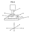
- Fig. 3 is a schematic diagram illustrating a method for forming a phase separation region according to each example.
- the present invention provides a method for locally phase-separating a focal area or its vicinity in a glass containing a metastable immiscible phase by the irradiation of a laser pulse.
- a homogeneous glass can be prepared from Ge-GeO 2 , R 2 O-SiO 2 (R: Li, Na), BaO-SiO 2 , R 2 O-B 2 O 3 (R: Li, Na, K, Rb, Cs), RF-BeF 2 (R: Li, Na, K, Rb, Cs), Na 2 O-CaO-SiO 2 , Na 2 O-B 2 O 3 -SiO 2 , PbO-GeO-SiO 2 , Ge-Te-Sb, Ge-Te-As, or other glasses that contain a metastable immiscible phase.
- a laser pulse on these glasses allows phase separation to occur only at an irradiated area.
- the pulse width, pulse energy, or repetition frequency of a laser is not limited to a specific value and is determined so that an energy sufficient to melt a focal area to induce phase separation is transferred to a glass, and that a sufficient heat for the growth of phase separation is accumulated.
- the pulse width of a laser is 10 picoseconds or less to prevent dielectric breakdown and cracking in the glass.
- a pulse width less than 10 femtoseconds is difficult to maintain and is therefore not practical.
- the peak power of a pulsed laser decreases with increasing the pulse width.
- the peak energy of a laser pulse should be large to maintain the peak power density with increased pulse width.
- a laser having the same wavelength as that of the intrinsic absorption of a glass is absorbed into a surface of the glass and cannot provide a phase separation region exclusively inside the glass.
- the peak power of a pulsed laser is an output energy (J) per pulse divided by a pulse width (second) and is expressed in watts (W).
- the peak power density is a peak power per unit area (cm 2 ) and is expressed in W/cm 2 .
- the size of a phase separation region or the phase separation speed may be controlled by changing the pulse width, pulse energy, or repetition frequency of a laser.
- the wavelength of a laser is different from that of the intrinsic absorption of a glass.
- a phase separation region can be formed only in the vicinity of the focal point.
- heating over a glass to a temperature at which no phase separation occurs enables a local phase separation with a low-power pulsed laser and increases the speed of phase separation.
- phase separation In general, phase separation generates two or more phases mixed on the order of angstroms to micrometers. These phases have no effect on visible to infrared light or are just scattering factors. Thus, such phase separation has no use in optical applications.
- a method for forming a phase separation region in a glass according to the present invention allows a single separated phase to grow to a certain size.
- the present method can also form a phase separation region continuously or regularly in a desired position.
- phase separation can be utilized to control the guide, reflection, or refraction of light.
- moving the focal point of a laser continuously or intermittently in a three-dimensional XYZ space relative to a glass can generate a two-dimensional or three-dimensional phase separation region of any shape and any size, such as a linear phase separation region or a dotted phase separation region, in the glass.
- the control of the guide, reflection, or refraction of light utilizing the phase separation according to the present method has little effect when the regional size is less than 200 nm.
- one of two or more separated phases preferably grows to have a regional size of 200 nm or more.
- two or more unclearly separated or mixed phases at a focal point of a laser or in the vicinity thereof produce an unclear boundary, making a design to control the guide, reflection, or refraction of light difficult.
- the light had a pulse energy of 1 ⁇ J, a cycle period of 250 kHz, and a wavelength of 800 nm.
- phase separation region had different phases with a clear boundary at the focal point and its vicinity.
- the glass sample 14 was then cut and grinded so that the phase separation region appeared on the surface.
- EPMA line analysis of compositions of each phase in the borosilicate glass sample 14 showed that a central phase was mainly composed of boric acid and its surrounding phase was mainly composed of quartz.
- the glass sample 14 was continuously irradiated with the laser under the same conditions as in EXAMPLE 1, except that the glass sample 14 was scanned in the X direction while the YZ axes were fixed. This continuously formed two separated phases in the glass sample 14.
- the glass sample 14 was irradiated with the laser under the same conditions as in EXAMPLE 1, except that the objective lens was replaced with one having NA of 0.4 and a magnification of 20, and that the glass sample 14 was scanned in the Z direction while fixed on the XY axes.
- the pulse width of the laser was adjusted to the penetration depth so as to maintain the pulse width in the glass sample 14 constant.
- a phase separation region was linearly formed or grown in the Z direction, as in the scanning in the X direction.
- a linear phase separation region was formed in a PbO-GeO 2 -SiO 2 glass in place of the alkali borosilicate glass sample 14 in EXAMPLE 3. Light incident from an edge of the linear phase separation region was detected at the opposite edge as an outgoing light. This demonstrated that this linear phase separation region had an optical waveguide structure.
- a grinded alkali borosilicate glass sample 14 with dimensions of 20 x 20 x 1 mm was prepared as a glass containing a metastable immiscible phase.
- the glass sample 14 was preheated at a glass transition temperature with a heater mounted on the XYZ stage before laser radiation.
- a phase separation region having a diameter of about 20 ⁇ m was observed around a focal point.
- the glass sample 4 which was the same as that in EXAMPLE 5, was fixed on the Z axis so that a laser focal point was positioned near the bottom of the sample. While the sample was moved on an XY plane at 10 ⁇ m/s, a Q switch, mode lock Ti:sapphire laser excited by an argon ion laser (20W) was regeneratively amplified to emit a laser pulse at a cycle period of 10 pulses per second. Then, a motor-driven stage was moved by 500 ⁇ m in the Z direction (in such a direction that the focal point of the laser moved to the top of the glass sample 14), and the sample was irradiated with the laser on an XY plane as described above. This scanning procedure was repeated five times.
- a method for forming a phase separation region according to the present invention can induce phase separation in a small desired area in a glass containing a metastable immiscible phase without heating the entire glass.
- the present method can also be used to form a linear phase separation region or a dotted phase separation region in a glass.
- the linear phase separation region or the dotted phase separation region has a different refractive index from the surroundings.
- the present method is useful for preparing a step-index optical waveguide or a photonic crystal having regularly arranged high-refractive-index regions.
Landscapes
- Chemical & Material Sciences (AREA)
- Engineering & Computer Science (AREA)
- Geochemistry & Mineralogy (AREA)
- Organic Chemistry (AREA)
- Materials Engineering (AREA)
- Life Sciences & Earth Sciences (AREA)
- Chemical Kinetics & Catalysis (AREA)
- General Chemical & Material Sciences (AREA)
- Dispersion Chemistry (AREA)
- Ceramic Engineering (AREA)
- Crystallography & Structural Chemistry (AREA)
- Physics & Mathematics (AREA)
- Optics & Photonics (AREA)
- Health & Medical Sciences (AREA)
- Toxicology (AREA)
- Optical Integrated Circuits (AREA)
- Re-Forming, After-Treatment, Cutting And Transporting Of Glass Products (AREA)
- Surface Treatment Of Glass (AREA)
Abstract
Description
Claims (6)
- A method for forming a phase separation region, comprising:converging a laser pulse in a glass containing a metastable immiscible phase to separate only an area at a focal point of the laser or in the vicinity of the focal point into phases.
- The method for forming a phase separation region according to Claim 1, wherein one of the two or more separated phases in the phase separation region has a size of 200 nm or more.
- The method for forming a phase separation region according to Claim 1, wherein the two or more phases at a focal point of the laser or in the vicinity of the focal point are clearly separated.
- The method for forming a phase separation region according to any of Claims 1 through 3, wherein the focal point of the laser is moved continuously or intermittently relative to the glass to form a linear phase separation region or a dotted phase separation region in two or three dimensions in the glass.
- The method for forming a phase separation region according to Claim 1, wherein the glass containing a metastable immiscible phase is Ge-GeO2, R2O-SiO2 (R: Li, Na), BaO-SiO2, R2O-B2O3 (R: Li, Na, K, Rb, Cs), RF-BeF2 (R: Li, Na, K, Rb, Cs), Na2O-CaO-SiO2, Na2O-B2O3-SiO2, PbO-GeO-SiO2, Ge-Te-Sb, or Ge-Te-As.
- The method for forming a phase separation region according to Claim 1, wherein the pulse width of the laser is between 10 femtoseconds and 10 picoseconds, and the wavelength of the laser is different from that of the intrinsic absorption of the glass.
Applications Claiming Priority (3)
| Application Number | Priority Date | Filing Date | Title |
|---|---|---|---|
| JP2002124725A JP2003321252A (en) | 2002-04-25 | 2002-04-25 | Method of forming phase separation region inside glass |
| JP2002124725 | 2002-04-25 | ||
| PCT/JP2003/005015 WO2003091176A1 (en) | 2002-04-25 | 2003-04-18 | Method of forming split phase area inside glass |
Publications (1)
| Publication Number | Publication Date |
|---|---|
| EP1502901A1 true EP1502901A1 (en) | 2005-02-02 |
Family
ID=29267535
Family Applications (1)
| Application Number | Title | Priority Date | Filing Date |
|---|---|---|---|
| EP03717659A Withdrawn EP1502901A1 (en) | 2002-04-25 | 2003-04-18 | Method of forming split phase area inside glass |
Country Status (5)
| Country | Link |
|---|---|
| US (1) | US20050193771A1 (en) |
| EP (1) | EP1502901A1 (en) |
| JP (1) | JP2003321252A (en) |
| CN (1) | CN1321337C (en) |
| WO (1) | WO2003091176A1 (en) |
Families Citing this family (11)
| Publication number | Priority date | Publication date | Assignee | Title |
|---|---|---|---|---|
| DE102004037949B4 (en) * | 2004-08-05 | 2009-04-02 | Forschungszentrum Karlsruhe Gmbh | Process for the preparation of photonic crystals |
| US8629610B2 (en) | 2006-01-12 | 2014-01-14 | Ppg Industries Ohio, Inc. | Display panel |
| ES2383915T3 (en) | 2006-01-12 | 2012-06-27 | Ppg Industries Ohio, Inc. | Display panel with redirection characteristics of laser-produced light |
| JP5275729B2 (en) * | 2008-09-16 | 2013-08-28 | 国立大学法人京都大学 | Transparent material for optical parts producing composition distribution and optical part using the same |
| KR20130106770A (en) * | 2010-07-26 | 2013-09-30 | 하마마츠 포토닉스 가부시키가이샤 | Method for manufacturing semiconductor device |
| AU2011335892B2 (en) * | 2010-12-03 | 2015-05-14 | Adelaide Research & Innovation Pty Ltd | Element for the amplification of a light and method of making the same |
| JPWO2015037513A1 (en) * | 2013-09-13 | 2017-03-02 | コニカミノルタ株式会社 | Water repellent glass, method for producing the same, and water repellent film using the same |
| JP7067736B2 (en) * | 2017-12-08 | 2022-05-16 | 日本電気硝子株式会社 | Processing method of fine periodic structure using pulse laser and glass body |
| CN109445017A (en) * | 2019-01-02 | 2019-03-08 | 京东方科技集团股份有限公司 | Light guide plate and preparation method thereof, backlight module and display device |
| US20220025517A1 (en) * | 2020-07-27 | 2022-01-27 | Enchip Enterprise Llc | Semiconductor Processing System, and Control Assembly and Method Thereof |
| CN114212985B (en) * | 2021-12-14 | 2023-04-21 | 华南理工大学 | Preparation method of glass ceramics based on defect-induced spatially selective crystallization |
Family Cites Families (4)
| Publication number | Priority date | Publication date | Assignee | Title |
|---|---|---|---|---|
| CN1365500A (en) * | 1999-07-29 | 2002-08-21 | 康宁股份有限公司 | Direct writing of optical device in silica-based glass using femtosecond pulse lasers |
| KR20020038786A (en) * | 1999-09-30 | 2002-05-23 | 알프레드 엘. 미첼슨 | Deep UV laser internally induced densification in silica glasses |
| JP4132750B2 (en) * | 2001-08-17 | 2008-08-13 | 独立行政法人科学技術振興機構 | Fabrication method of quantum dot device by femtosecond laser irradiation |
| EP1293810A1 (en) * | 2001-09-12 | 2003-03-19 | Agilent Technologies, Inc. (a Delaware corporation) | A method of producing optical waveguides in a tellurite glass |
-
2002
- 2002-04-25 JP JP2002124725A patent/JP2003321252A/en active Pending
-
2003
- 2003-04-18 WO PCT/JP2003/005015 patent/WO2003091176A1/en not_active Ceased
- 2003-04-18 CN CNB038089335A patent/CN1321337C/en not_active Expired - Fee Related
- 2003-04-18 US US10/512,159 patent/US20050193771A1/en not_active Abandoned
- 2003-04-18 EP EP03717659A patent/EP1502901A1/en not_active Withdrawn
Non-Patent Citations (1)
| Title |
|---|
| See references of WO03091176A1 * |
Also Published As
| Publication number | Publication date |
|---|---|
| WO2003091176A1 (en) | 2003-11-06 |
| JP2003321252A (en) | 2003-11-11 |
| CN1321337C (en) | 2007-06-13 |
| US20050193771A1 (en) | 2005-09-08 |
| CN1646442A (en) | 2005-07-27 |
Similar Documents
| Publication | Publication Date | Title |
|---|---|---|
| Chan et al. | Modification of the fused silica glass network associated with waveguide fabrication using femtosecond laser pulses | |
| JP5629912B2 (en) | Structure and manufacturing method thereof | |
| KR102096189B1 (en) | Method for creating deformation in or on a polyphase transparent work piece by laser processing and polyphase composite materials | |
| US20050193771A1 (en) | Method of forming split phase area inside glass | |
| Xiong et al. | Ultrafast laser micromachining the ultra-low expansion glass-ceramic: Optimization of processing parameters and physical mechanism | |
| Okhrimchuk et al. | Phase transformation under direct laser writing in a YAG single crystal | |
| Lipat’Ev et al. | Specifics of the crystallization of lanthanum borogermanate glass by a femtosecond laser beam | |
| Fedotov et al. | Local formation of birefringent structures in alkali-silicate glass by femtosecond laser beam | |
| Doosti et al. | Laser-induced and space-selective crystallization of yttrium aluminum garnet crystal from SiO 2/Al 2 O 3/Y 2 O 3/KF/Na 2 O/AlF 3/B 2 O 3 glass system | |
| JP2010150117A (en) | Crystallized glass and process for producing same | |
| Lotarev et al. | Laser writing of polarization-sensitive birefringence in sodium-borosilicate glass | |
| Takeshima et al. | Precipitation of silver particles by femtosecond laser pulses inside silver-ion doped glass | |
| Ren-Xi et al. | Femtosecond laser induced optical waveguides and micro-mirrors inside glasses | |
| Hewak | Non-toxic sulfide glasses and thin films for optical applications | |
| Ohfuchi et al. | The characteristic of birefringence and optical loss in femtosecond-laser-induced region in terms of nanogratings distribution | |
| Babu et al. | Study of femtosecond laser writing in the bulk of Nd3+, Y3+ co-doped CaF2 crystals | |
| Sakurai et al. | Photoinduced Structural Change in MgO Single Crystal | |
| Ye et al. | Thermal stress-induced birefringence in borate glass irradiated by femtosecond laser pulses | |
| Veiko et al. | Physical mechanisms of CO2-laser-induced rapid structural changes in glass-ceramics | |
| Lancry et al. | Porous nanogratings and related form birefringence in silicate and germanate glasses | |
| Shimotsuma et al. | Photosensitivity in glasses | |
| Fedotov et al. | Polarization-dependent birefringence in sodium aluminoborate glasses | |
| RU2627017C1 (en) | Method for manufacturing waveguide in volume of plate made of porous optical material | |
| Panahibakhsh et al. | Patterning of silica MCM-41 high-order material on a glass surface by XeCl laser irradiation | |
| Qin-Ling et al. | Near-infrared femtosecond laser induced defect formation in high purity silica below the optical breakdown threshold |
Legal Events
| Date | Code | Title | Description |
|---|---|---|---|
| PUAI | Public reference made under article 153(3) epc to a published international application that has entered the european phase |
Free format text: ORIGINAL CODE: 0009012 |
|
| 17P | Request for examination filed |
Effective date: 20041116 |
|
| AK | Designated contracting states |
Kind code of ref document: A1 Designated state(s): AT BE BG CH CY CZ DE DK EE ES FI FR GB GR HU IE IT LI LU MC NL PT RO SE SI SK TR |
|
| AX | Request for extension of the european patent |
Extension state: AL LT LV MK |
|
| RIN1 | Information on inventor provided before grant (corrected) |
Inventor name: HIRAO, KAZUYUKI Inventor name: FUJIWARA, SEIJI Inventor name: MIURA, KIYOTAKA |
|
| STAA | Information on the status of an ep patent application or granted ep patent |
Free format text: STATUS: THE APPLICATION HAS BEEN WITHDRAWN |
|
| 18W | Application withdrawn |
Effective date: 20071126 |