EP1502837A1 - Vehicle power steering apparatus capable of suppressing vibration of EPS motor during changes in steering angle - Google Patents
Vehicle power steering apparatus capable of suppressing vibration of EPS motor during changes in steering angle Download PDFInfo
- Publication number
- EP1502837A1 EP1502837A1 EP04016363A EP04016363A EP1502837A1 EP 1502837 A1 EP1502837 A1 EP 1502837A1 EP 04016363 A EP04016363 A EP 04016363A EP 04016363 A EP04016363 A EP 04016363A EP 1502837 A1 EP1502837 A1 EP 1502837A1
- Authority
- EP
- European Patent Office
- Prior art keywords
- drive current
- pulsation
- power steering
- value
- specific condition
- Prior art date
- Legal status (The legal status is an assumption and is not a legal conclusion. Google has not performed a legal analysis and makes no representation as to the accuracy of the status listed.)
- Granted
Links
Images
Classifications
-
- B—PERFORMING OPERATIONS; TRANSPORTING
- B62—LAND VEHICLES FOR TRAVELLING OTHERWISE THAN ON RAILS
- B62D—MOTOR VEHICLES; TRAILERS
- B62D5/00—Power-assisted or power-driven steering
- B62D5/04—Power-assisted or power-driven steering electrical, e.g. using an electric servo-motor connected to, or forming part of, the steering gear
- B62D5/0457—Power-assisted or power-driven steering electrical, e.g. using an electric servo-motor connected to, or forming part of, the steering gear characterised by control features of the drive means as such
- B62D5/046—Controlling the motor
- B62D5/0472—Controlling the motor for damping vibrations
Definitions
- the present invention relates to a power steering apparatus for a vehicle, which suppresses vehicle vibration that may occur due to lateral forces acting on tires of the vehicle while the steering direction of the corresponding vehicle wheels is being changed.
- a signal (referred to in the following as the steering signal) is generated in accordance with the degree to which the steering wheel is being actuated by the vehicle driver, e.g., based on sensing the amount and direction of torque that is being applied to the steering column by the driver.
- the steering signal is produced from a power steering ECU (Electronic Control Unit), and an EPS (Electrical Power Steering) motor is driven based on that signal, to apply a supplementary amount of torque to a steering mechanism linked to the front wheels, such that the angle of the front wheels is adjusted appropriately.
- EPS Electronic Power Steering
- the vibration may result in resonant vibration of the vehicle body and the steering wheel, causing sensations of discomfort to the driver. Furthermore, this phenomenon results in instability of the reaction forces between the tires and the road surface, so that there is a lowering of stability of vehicle motion.
- the invention provides a power steering apparatus for a vehicle, having a control section which produces a drive current in accordance with an amount of steering actuation applied by a driver of the vehicle and an electrical power steering motor that is driven by the drive current to adjust a steering angle of front wheels of the vehicle, with such a power steering apparatus being characterized in that the control section is configured with:
- the control section detects the frequency of any pulsation (i.e., appearing as a superimposed ripple component) of the drive current, to determine whether such pulsation is being caused by occurrence of the aforementioned specific condition, i.e., due to lateral forces acting on the tires during adjustment of the steering angle. That is to say, if it is found that the frequency of such pulsation is close to a specific predetermined frequency which is indicative of that condition of vibration, then the control section judges that the specific condition is occurring.
- any pulsation i.e., appearing as a superimposed ripple component
- the control section detects the amplitude of such pulsation of the drive current of the power steering motor.
- the control section effects removal of the pulsation from the drive current.
- this is executed only if it has been judged that the frequency of the pulsation is close to the aforementioned specific predetermined frequency (i.e., is within a predetermined range of frequencies centered on that predetermined frequency). In that case, it can be ensured that operations to effect removal of the pulsation is performed only when such pulsation is being caused by the aforementioned specific condition, i.e., due to lateral forces acting on the tires during adjustment of the steering angle.
- the control section detects the phase of such pulsation of the power steering motor drive current, and when is judged as described above that the pulsation is being caused by the aforementioned specific condition, i.e., due to lateral forces acting on the tires during adjustment of the steering angle, then the control section adds to the drive current a periodically varying current that is of inverse phase to the aforementioned pulsation of the drive current, such as to cancel and thereby suppress the pulsation.
- a supplementary value of drive current is determined in accordance with the rate of change of the drive current immediately before the start of occurrence of the pulsation.
- the level of drive current which is actually supplied to the power steering motor is determined by combining the supplementary value with the value of drive current that is necessary to provide a required amount of torque assistance to the steering mechanism. The actual level of drive current supplied to the power steering motor can thereby be established such as to effectively suppress occurrence of the pulsation, during the masking interval.
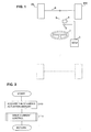
- Fig. 1 is a conceptual diagram of an embodiment of a power steering apparatus according to the present invention. The configuration and operation of this apparatus will be described in the following.
- this power steering apparatus is made up of a steering wheel 1, a steering sensor 2, a steering ECU 3, an EPS motor 4, a steering shaft 5, a tie rod 6 and two front wheels FL, FR.
- the steering wheel 1 is actuated by the vehicle driver in accordance with his intentions for driving the vehicle, and the steering sensor 2 detects an amount of actuation of the steering wheel 1 by the vehicle driver.
- the steering ECU 3 constitutes a control section of this embodiment, which receives a detection signal that is produced by the steering sensor 2 (e.g., indicative of the amount of turning force being applied to the steering wheel 1 by the driver) and produces a drive current which is supplied to drive the EPS motor 4, with the level of that drive current being determined in accordance with the detection signal from the steering sensor 2.
- the steering shaft 5 is connected to the tie rod 6 via a linkage mechanism, and the EPS motor 4 is coupled to that linkage mechanism such as to move both of the front wheels FL, FR in a common direction.
- Fig. 2 shows a main processing routine, which is repetitively performed by the steering ECU 3 of this embodiment, after the ignition switch of the vehicle has been turned on.
- step S100 the degree of actuation (e.g., measured as an amount of torque) that is being applied by the vehicle driver is acquired based on the detection signal from the steering sensor 2.
- step S110 drive current control is applied to the EPS motor 4 based on the steering actuation amount which has been acquired.
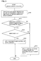
- Fig. 3 is a flow diagram of the drive current processing of S110 of Fig. 2.
- step S200 the frequency and phase of a ripple component of the drive current are measured.
- step S210 a decision is made as to whether or not the frequency of that ripple component is within a predetermined range of frequencies that is centered on 10 Hz. This judgement is performed in order to determine whether fluctuations in the motor drive current are being caused by vibration of the rubber of the tires, caused by lateral forces acting on the tires. Since such vibration of the tire rubber has a frequency of approximately 10 Hz, the occurrence of such vibration can be reliably detected by judging whether or not the frequency of a ripple component of the motor drive current (i.e., caused by vibration of the motor shaft) is approximately 10 Hz.
- step S210 If a YES decision is made in step S210, then since this indicates that fluctuation (i.e., ripple) of the drive current of the EPS motor 4 is occurring due to vibration of the tire rubber caused by lateral forces on the tires, operation proceeds to step S220. Conversely if a NO decision is made in step S210, then since this indicates that the ripple component in the motor drive current is not caused by vibration due to such lateral forces acting on the tire rubber, operation proceeds to step S230, in which a level of drive current is supplied to the EPS motor 4 that is determined in accordance with the steering actuation amount that has been acquired in step S100 of Fig. 2. Processing then ends.
- fluctuation i.e., ripple
- step S220 a decision is made as to whether the amplitude of the ripple component in the drive current of the EPS motor 4 exceeds a predetermined value, designated as the value A.
- a predetermined value designated as the value A.
- vibration of the tires caused by lateral forces acting on them is transmitted to the power steering apparatus, thereby affecting the output power of the EPS motor 4, and producing pulsation in the drive current which flows in the EPS motor 4.
- the amplitude of the pulsation in the drive current is compared with the predetermined amplitude value A. That amplitude value A is established based upon factors such as the rigidity of the shaft of the EPS motor 4 and the level of motor drive power, and so must be established in accordance with the characteristics of each particular vehicle model.
- step S220 If it is found that the amplitude of the pulsation of the drive current exceeds the predetermined value A, i.e., a YES decision is made in step S220, then this indicates that vibration of the tire rubber is being transmitted through the steering mechanism to the EPS motor 4, causing the pulsation in the drive current, and so operation proceeds to step S240. If there is a NO decision made in step S220, then operation proceeds to step S230 described above.
- step S240 inverse phase current control is applied, whereby a current which is of equal frequency and amplitude to the ripple (i.e., pulsation) of the drive current of the EPS motor 4 and is of opposite phase to the ripple is added to the motor drive current.
- This processing is performed based on the values for frequency, phase and amplitude that have been obtained for the ripple component in the drive current in step S200 as described above.
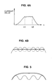
- Fig. 4A is a simplified diagram of an example of the variation with respect to time of the drive current of the EPS motor 4 when vibration of the tire rubber occurs due to the action of lateral forces acting on the tires as described above.
- the vibration occurs in an interval between time points designated as t1, t2.
- drive current control applied as described above referring to Fig. 3
- if for example the onset of the vibration is detected immediately after time point t1 in the example of Fig. 4A, (i.e., there is a YES decision reached in step S220, in an execution of the processing routine of Fig.
- inverse phase current control is applied until a time point (corresponding to the time point t2) at which no lateral vibration of the tires will occur (e.g., a point at which the steering ECU 3 determines that no further torque assistance is to be applied by the steering motor 4).
- vibration of the shaft of the EPS motor is suppressed, so that transfer of such vibration from the EPS motor to the body of the vehicle is eliminated, and the driver discomfort which can be caused by such vibration of the vehicle body is thereby eliminated.
- greater stability of the vehicle motion can be achieved.
- inverse phase current control is applied in step 240 of Fig. 3 as described above.
- masking processing refers to a technique of selecting an interval during which drive current is being supplied to the EPS motor 4 (specifically, an interval in which the aforementioned pulsation will occur unless they are suppressed) and, during that masking interval, determining the level of drive current such as to ensure that the pulsation will be suppressed, rather than determining the level of drive current only in accordance with the required amount of supplementary torque that is to be applied to the steering mechanism.
- a masking interval begins (e.g., extending between the time points t1, t2 in the example of Fig. 4A).
- a supplementary level of drive current for the EPS motor 4 is determined based on the rate of change of amplitude of the drive current which occurred immediately prior to the start of the pulsation (e.g., immediately before the time point t1 in the example of Fig. 4A).
- the value of rate of change can for example be that which is obtained during an interval of fixed duration, immediately preceding the point at which pulsation of the drive current has started to occur which satisfies the aforementioned conditions.
- the supplementary level of drive current is combined in a predetermined manner with the level of drive current that has been determined as necessary for producing the required level of torque assistance to thereby determine the actual level of drive current that is supplied to the EPS motor 4 during the masking interval.
- the supplementary level of drive current is predetermined such that the resultant actual level of drive current of the EPS motor 4 will effectively suppress the occurrence of the aforementioned drive current pulsation.
- the drive current of the EPS motor 4 is thereafter controlled to a suitable level to suppress the drive current pulsation, until the time point t2.
- the variation of the drive current during the interval from t1 to t2 becomes as illustrated by the thick-line portion of Fig. 5, with the drive current pulsation being effectively eliminated.
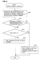
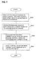
- the drive current control processing of this embodiment is illustrated in the flow diagram of Fig. 6, in which processing steps corresponding to those of Fig. 3 of the first embodiment are indicated by identical designations to those of Fig. 3. As shown, the processing differs from that of Fig. 3 in that the drive current masking control described above is executed in step S241, in accordance with the rate of change of the motor drive current immediately prior to the start of occurrence of drive current pulsation (the latter being detected as YES decisions in each of the steps S210, S220, as described for the first embodiment).
- step S241 in Fig. 6 are basically as illustrated in the flow diagram of Fig. 7.
- a value of rate of change of motor drive current that had been acquired and registered immediately previously is read out (step S300). That value is then used in calculating an appropriate value of supplementary current necessary for achieving suppression of the pulsation in the drive current (step S310).
- the actual level of drive current which is to be supplied to the EPS motor 4 is then calculated (step S320) based on that supplementary current value in combination with the drive current value most recently established in step S230 of Fig. 6.
- the motor drive current is then controlled to be in accordance with that calculated value (step S330).
- this embodiment can achieve similar effects to those of the first embodiment, by suppressing the effects of vibration of the vehicle tires caused by the action of lateral forces on the tires and hence on the EPS motor, thereby eliminating a cause of driver discomfort due to vibration of the vehicle body, and achieving improved stability of vehicle motion.
Landscapes
- Engineering & Computer Science (AREA)
- Chemical & Material Sciences (AREA)
- Combustion & Propulsion (AREA)
- Transportation (AREA)
- Mechanical Engineering (AREA)
- Steering Control In Accordance With Driving Conditions (AREA)
- Power Steering Mechanism (AREA)
Abstract
Description
Claims (7)
- A power steering apparatus for a vehicle, having a control section which produces a drive current having a value determined in accordance with an amount of steering actuation that applied by a driver of said vehicle, and an electrical power steering motor that is driven by said drive current to adjust a steering angle of front wheels of said vehicle;
wherein said control section comprises:means for detecting a specific condition of pulsation of said drive current due to vibration of rubber of tires which are mounted on said front wheels, said vibration being caused by lateral forces acting on said front wheels, andmeans responsive to said detection of said specific condition of pulsation for supplying to said power steering motor a current which is free from said pulsation, as said drive current. - A power steering apparatus according to claim 1, wherein said control section comprises means for detecting said specific condition of pulsation based on judgement of occurrence of a frequency component of said drive current that is substantially close to a predetermined frequency, said predetermined frequency having been selected as a frequency corresponding to said specific condition.
- A power steering apparatus according to claim 2, wherein said control section comprises means for:measuring a value of phase of pulsation of said drive current, andwhen said specific condition of pulsation is detected, effecting removal of said pulsation by adding to said drive current a current which varies periodically at said frequency of said pulsation and is of opposite phase to said pulsation.
- A power steering apparatus according to claim 2, wherein said control section comprises means for:measuring successive values of rate of change of said drive current,when said specific condition of pulsation is detected, determining a supplementary current value based upon a value of rate of change of drive current obtained immediately prior to said detection of the specific condition, andduring a masking interval which begins subsequent to said detection, determining an actual value of drive current that is supplied to said electrical power steering motor, said actual value being based upon said supplementary current value and upon said drive current value that is determined in accordance with said amount of steering actuation, in combination.
- A power steering apparatus according to claim 3, wherein said control section comprises means for:judging an amplitude of said pulsation when said specific condition of pulsation is detected, andwhen said amplitude exceeds a predetermined value, effecting removal of said pulsation from said drive current.
- A power steering apparatus according to claim 5, wherein said control section comprises means for:measuring a value of phase of pulsation of said drive current, andwhen said specific condition of pulsation is detected and said amplitude exceeds said predetermined value, effecting said removal of said pulsation by adding to said drive current a current which varies periodically at said frequency of said pulsation and is of opposite phase to said pulsation.
- A power steering apparatus according to claim 5, wherein said control section comprises means for:measuring successive values of rate of change of said drive current,when said specific condition of pulsation is detected, determining a supplementary current value based upon a value of rate of change of drive current obtained immediately prior to said detection of the specific condition, andduring a masking interval which begins subsequent to said detection, determining an actual value of drive current that is supplied to said electrical power steering motor, said actual value being based upon said supplementary current value and upon said drive current value that is determined in accordance with said amount of steering actuation, in combination.
Applications Claiming Priority (2)
| Application Number | Priority Date | Filing Date | Title |
|---|---|---|---|
| JP2003282872 | 2003-07-30 | ||
| JP2003282872A JP4033070B2 (en) | 2003-07-30 | 2003-07-30 | Power steering device |
Publications (2)
| Publication Number | Publication Date |
|---|---|
| EP1502837A1 true EP1502837A1 (en) | 2005-02-02 |
| EP1502837B1 EP1502837B1 (en) | 2006-11-22 |
Family
ID=33535685
Family Applications (1)
| Application Number | Title | Priority Date | Filing Date |
|---|---|---|---|
| EP04016363A Expired - Lifetime EP1502837B1 (en) | 2003-07-30 | 2004-07-12 | Vehicle power steering apparatus capable of suppressing vibration of EPS motor during changes in steering angle |
Country Status (4)
| Country | Link |
|---|---|
| US (1) | US7079929B2 (en) |
| EP (1) | EP1502837B1 (en) |
| JP (1) | JP4033070B2 (en) |
| DE (1) | DE602004003307T2 (en) |
Cited By (5)
| Publication number | Priority date | Publication date | Assignee | Title |
|---|---|---|---|---|
| EP1990257A1 (en) * | 2007-05-07 | 2008-11-12 | Jtekt Corporation | Electric power steering apparatus |
| US20090294206A1 (en) * | 2008-05-30 | 2009-12-03 | Gm Global Technology Operations, Inc. | Reducing The Effects Of Vibrations In An Electric Power Steering (EPS) System |
| EP2221236A4 (en) * | 2007-12-14 | 2011-10-26 | Mitsubishi Electric Corp | CONTROL DEVICE FOR POWER ASSISTED STEERING |
| US9266558B2 (en) | 2010-09-15 | 2016-02-23 | GM Global Technology Operations LLC | Methods, systems and apparatus for steering wheel vibration reduction in electric power steering systems |
| US9440674B2 (en) | 2010-09-15 | 2016-09-13 | GM Global Technology Operations LLC | Methods, systems and apparatus for steering wheel vibration reduction in electric power steering systems |
Families Citing this family (16)
| Publication number | Priority date | Publication date | Assignee | Title |
|---|---|---|---|---|
| KR100966270B1 (en) | 2004-11-15 | 2010-06-28 | 주식회사 만도 | Vehicle Active Steering |
| DE102006016852A1 (en) * | 2006-04-07 | 2007-10-11 | Daimlerchrysler Ag | Automotive road surface sensor is attached to steering wheel column and driver alert display |
| US20080066991A1 (en) | 2006-09-15 | 2008-03-20 | Denso Corporation | On-vehicle control apparatus powered by on-vehicle battery |
| EP1982896B1 (en) * | 2007-04-20 | 2010-01-27 | Jtekt Corporation | Electric power steering apparatus |
| JP4468415B2 (en) * | 2007-06-29 | 2010-05-26 | 三菱電機株式会社 | Electric power steering control device |
| JP5262005B2 (en) * | 2007-07-13 | 2013-08-14 | 株式会社ジェイテクト | Electric power steering device |
| DE202007014209U1 (en) * | 2007-10-10 | 2009-02-26 | Autoliv Development Ab | Driver alarm system for the steering wheel of a motor vehicle |
| GB2454788B (en) * | 2007-11-14 | 2012-07-11 | Ford Global Tech Llc | Active steering nibble control algorithm for electric steering systems |
| US8219283B2 (en) * | 2007-11-14 | 2012-07-10 | Ford Global Technologies | Active steering nibble control algorithm for electric steering systems |
| DE102008036001B4 (en) * | 2008-08-01 | 2020-01-23 | Ford Global Technologies, Llc | Method for operating a steering system for steering a motor vehicle, and steering system and motor vehicle |
| US8831854B2 (en) * | 2010-08-16 | 2014-09-09 | Chrysler Group Llc | Active shimmy mitigation |
| US9327762B2 (en) | 2010-12-14 | 2016-05-03 | GM Global Technology Operations LLC | Electric power steering systems with improved road feel |
| US9020659B2 (en) * | 2012-06-15 | 2015-04-28 | Ford Global Technologies, Llc | Dynamometer vehicle operating mode control |
| JP6417954B2 (en) * | 2015-01-19 | 2018-11-07 | 株式会社ジェイテクト | Automatic driving device |
| KR102354756B1 (en) * | 2018-02-27 | 2022-01-25 | 현대모비스 주식회사 | Apparatus and emthod for controlling steering sensation of motor driven power steering |
| CN121356212A (en) * | 2025-11-24 | 2026-01-16 | 江西天健龙维汽车部件有限公司 | Auxiliary winding electric power steering motor that actively suppresses vibration and torque ripple |
Citations (3)
| Publication number | Priority date | Publication date | Assignee | Title |
|---|---|---|---|---|
| US6122579A (en) * | 1999-05-28 | 2000-09-19 | Delphi Technologies, Inc. | Electric power steering control with torque ripple and road disturbance damper |
| EP1308368A2 (en) * | 2001-11-05 | 2003-05-07 | Koyo Seiko Co., Ltd. | Electric power steering apparatus |
| WO2003076251A1 (en) * | 2002-03-13 | 2003-09-18 | Koyo Steering Europe (K.S.E.) | Method for damping parasitic vibrations from the front subframe of a motor vehicle |
Family Cites Families (15)
| Publication number | Priority date | Publication date | Assignee | Title |
|---|---|---|---|---|
| JPS58152131A (en) | 1982-03-08 | 1983-09-09 | Toyota Motor Corp | Lowering of acceleration shock on vehicle |
| JP2568817B2 (en) * | 1984-11-29 | 1997-01-08 | 富士重工業株式会社 | Motor control device for electric power steering device |
| US4996261A (en) * | 1986-10-08 | 1991-02-26 | The United States Of America As Represented By The Secretary Of The Navy | Anti-fouling castable polymers and anti-fouling polyurethanes and similar materials |
| JPH0266360A (en) | 1988-07-07 | 1990-03-06 | Atsugi Unisia Corp | Automatic transmission power transmission device |
| JPH04121421A (en) | 1990-09-10 | 1992-04-22 | Nissan Motor Co Ltd | Power plant structure for vehicle |
| JP3172333B2 (en) * | 1993-06-04 | 2001-06-04 | 本田技研工業株式会社 | Vehicle steering system |
| JPH08276760A (en) | 1995-04-05 | 1996-10-22 | Toyota Motor Corp | Drive force distribution controller for four-wheel drive vehicle |
| JP2864474B2 (en) | 1995-11-27 | 1999-03-03 | 本田技研工業株式会社 | Electric power steering device |
| JP3666778B2 (en) | 1997-08-27 | 2005-06-29 | 本田技研工業株式会社 | Electric power steering device |
| JP3753511B2 (en) * | 1997-08-27 | 2006-03-08 | 本田技研工業株式会社 | Electric power steering device |
| US6107767A (en) * | 1998-03-20 | 2000-08-22 | Trw Inc. | Electric assist steering system having an improved motor current controller with notch filter |
| JP3712876B2 (en) * | 1998-12-01 | 2005-11-02 | 三菱電機株式会社 | Electric power steering control device |
| JP3298006B2 (en) * | 1998-12-24 | 2002-07-02 | 日本精工株式会社 | Control device for electric power steering device |
| JP2001151123A (en) | 1999-11-22 | 2001-06-05 | Nsk Ltd | Electric power steering device for vehicles |
| US6498451B1 (en) * | 2000-09-06 | 2002-12-24 | Delphi Technologies, Inc. | Torque ripple free electric power steering |
-
2003
- 2003-07-30 JP JP2003282872A patent/JP4033070B2/en not_active Expired - Fee Related
-
2004
- 2004-07-12 DE DE602004003307T patent/DE602004003307T2/en not_active Expired - Lifetime
- 2004-07-12 EP EP04016363A patent/EP1502837B1/en not_active Expired - Lifetime
- 2004-07-13 US US10/889,077 patent/US7079929B2/en not_active Expired - Lifetime
Patent Citations (3)
| Publication number | Priority date | Publication date | Assignee | Title |
|---|---|---|---|---|
| US6122579A (en) * | 1999-05-28 | 2000-09-19 | Delphi Technologies, Inc. | Electric power steering control with torque ripple and road disturbance damper |
| EP1308368A2 (en) * | 2001-11-05 | 2003-05-07 | Koyo Seiko Co., Ltd. | Electric power steering apparatus |
| WO2003076251A1 (en) * | 2002-03-13 | 2003-09-18 | Koyo Steering Europe (K.S.E.) | Method for damping parasitic vibrations from the front subframe of a motor vehicle |
Cited By (8)
| Publication number | Priority date | Publication date | Assignee | Title |
|---|---|---|---|---|
| EP1990257A1 (en) * | 2007-05-07 | 2008-11-12 | Jtekt Corporation | Electric power steering apparatus |
| US7909131B2 (en) | 2007-05-07 | 2011-03-22 | Jtekt Corporation | Electric power steering apparatus |
| EP2221236A4 (en) * | 2007-12-14 | 2011-10-26 | Mitsubishi Electric Corp | CONTROL DEVICE FOR POWER ASSISTED STEERING |
| US8326493B2 (en) | 2007-12-14 | 2012-12-04 | Mitsubishi Electric Corporation | Motor driven power steering control apparatus for suppressing vibration |
| US20090294206A1 (en) * | 2008-05-30 | 2009-12-03 | Gm Global Technology Operations, Inc. | Reducing The Effects Of Vibrations In An Electric Power Steering (EPS) System |
| US8744682B2 (en) * | 2008-05-30 | 2014-06-03 | GM Global Technology Operations LLC | Reducing the effects of vibrations in an electric power steering (EPS) system |
| US9266558B2 (en) | 2010-09-15 | 2016-02-23 | GM Global Technology Operations LLC | Methods, systems and apparatus for steering wheel vibration reduction in electric power steering systems |
| US9440674B2 (en) | 2010-09-15 | 2016-09-13 | GM Global Technology Operations LLC | Methods, systems and apparatus for steering wheel vibration reduction in electric power steering systems |
Also Published As
| Publication number | Publication date |
|---|---|
| US20050027417A1 (en) | 2005-02-03 |
| JP2005047426A (en) | 2005-02-24 |
| DE602004003307D1 (en) | 2007-01-04 |
| EP1502837B1 (en) | 2006-11-22 |
| JP4033070B2 (en) | 2008-01-16 |
| US7079929B2 (en) | 2006-07-18 |
| DE602004003307T2 (en) | 2007-06-21 |
Similar Documents
| Publication | Publication Date | Title |
|---|---|---|
| EP1502837B1 (en) | Vehicle power steering apparatus capable of suppressing vibration of EPS motor during changes in steering angle | |
| JP5962312B2 (en) | Electric power steering control device | |
| US6938725B2 (en) | Steering control apparatus | |
| EP1707473B1 (en) | Steering control apparatus with return torque control | |
| JP4353058B2 (en) | Control device for electric power steering device | |
| EP1319575B1 (en) | Apparatus and method for controlling electric power steering system | |
| EP0282041A2 (en) | A yaw motion control device for a vehicle | |
| WO2008032884A1 (en) | On-vehicle control apparatus powered by on-vehicle battery | |
| US20010017229A1 (en) | Electric power steering system | |
| JP4377331B2 (en) | Method and apparatus for detecting a driver's attention level | |
| JP4776656B2 (en) | Electric power steering control device | |
| US12312024B2 (en) | Control device, drive device, electric power steering device, and control method | |
| US12157525B2 (en) | Vibration reducing for power steering inversely proportional to the steering angle | |
| US7128184B2 (en) | Motor-driven power steering control apparatus | |
| CN115837845B (en) | Electric vehicle | |
| JP4039305B2 (en) | Electric power steering device for vehicles | |
| JP4779680B2 (en) | Vehicle in which power steering device is controlled based on vibration of steering wheel | |
| JPH06312666A (en) | Power steering device | |
| JPH0899648A (en) | Vehicle rear wheel steering system | |
| JP2004114918A (en) | Steering assist force control device | |
| JP3143605B2 (en) | Electric power steering control device | |
| JP5056351B2 (en) | Electric power steering device | |
| JP5055940B2 (en) | Electric power steering device | |
| JP5055941B2 (en) | Electric power steering device | |
| KR101558704B1 (en) | Control apparatus for MDPS having variable friction and controlling method for MDPS using of the same |
Legal Events
| Date | Code | Title | Description |
|---|---|---|---|
| PUAI | Public reference made under article 153(3) epc to a published international application that has entered the european phase |
Free format text: ORIGINAL CODE: 0009012 |
|
| AK | Designated contracting states |
Kind code of ref document: A1 Designated state(s): AT BE BG CH CY CZ DE DK EE ES FI FR GB GR HU IE IT LI LU MC NL PL PT RO SE SI SK TR |
|
| AX | Request for extension of the european patent |
Extension state: AL HR LT LV MK |
|
| 17P | Request for examination filed |
Effective date: 20050404 |
|
| AKX | Designation fees paid |
Designated state(s): DE FR GB |
|
| GRAP | Despatch of communication of intention to grant a patent |
Free format text: ORIGINAL CODE: EPIDOSNIGR1 |
|
| GRAS | Grant fee paid |
Free format text: ORIGINAL CODE: EPIDOSNIGR3 |
|
| GRAA | (expected) grant |
Free format text: ORIGINAL CODE: 0009210 |
|
| AK | Designated contracting states |
Kind code of ref document: B1 Designated state(s): DE FR GB |
|
| REG | Reference to a national code |
Ref country code: GB Ref legal event code: FG4D |
|
| REF | Corresponds to: |
Ref document number: 602004003307 Country of ref document: DE Date of ref document: 20070104 Kind code of ref document: P |
|
| ET | Fr: translation filed | ||
| PLBE | No opposition filed within time limit |
Free format text: ORIGINAL CODE: 0009261 |
|
| STAA | Information on the status of an ep patent application or granted ep patent |
Free format text: STATUS: NO OPPOSITION FILED WITHIN TIME LIMIT |
|
| 26N | No opposition filed |
Effective date: 20070823 |
|
| REG | Reference to a national code |
Ref country code: GB Ref legal event code: 746 Effective date: 20090313 |
|
| REG | Reference to a national code |
Ref country code: FR Ref legal event code: PLFP Year of fee payment: 12 |
|
| REG | Reference to a national code |
Ref country code: FR Ref legal event code: PLFP Year of fee payment: 13 |
|
| REG | Reference to a national code |
Ref country code: FR Ref legal event code: PLFP Year of fee payment: 14 |
|
| REG | Reference to a national code |
Ref country code: FR Ref legal event code: PLFP Year of fee payment: 15 |
|
| PGFP | Annual fee paid to national office [announced via postgrant information from national office to epo] |
Ref country code: FR Payment date: 20180725 Year of fee payment: 15 Ref country code: DE Payment date: 20180723 Year of fee payment: 15 |
|
| PGFP | Annual fee paid to national office [announced via postgrant information from national office to epo] |
Ref country code: GB Payment date: 20180719 Year of fee payment: 15 |
|
| REG | Reference to a national code |
Ref country code: DE Ref legal event code: R119 Ref document number: 602004003307 Country of ref document: DE |
|
| GBPC | Gb: european patent ceased through non-payment of renewal fee |
Effective date: 20190712 |
|
| PG25 | Lapsed in a contracting state [announced via postgrant information from national office to epo] |
Ref country code: DE Free format text: LAPSE BECAUSE OF NON-PAYMENT OF DUE FEES Effective date: 20200201 Ref country code: GB Free format text: LAPSE BECAUSE OF NON-PAYMENT OF DUE FEES Effective date: 20190712 |
|
| PG25 | Lapsed in a contracting state [announced via postgrant information from national office to epo] |
Ref country code: FR Free format text: LAPSE BECAUSE OF NON-PAYMENT OF DUE FEES Effective date: 20190731 |