EP1502808A2 - Neck rest for automobile seats, in particular rear seats - Google Patents
Neck rest for automobile seats, in particular rear seats Download PDFInfo
- Publication number
- EP1502808A2 EP1502808A2 EP04014210A EP04014210A EP1502808A2 EP 1502808 A2 EP1502808 A2 EP 1502808A2 EP 04014210 A EP04014210 A EP 04014210A EP 04014210 A EP04014210 A EP 04014210A EP 1502808 A2 EP1502808 A2 EP 1502808A2
- Authority
- EP
- European Patent Office
- Prior art keywords
- neck rest
- guiding
- supporting
- rest
- deformable
- Prior art date
- Legal status (The legal status is an assumption and is not a legal conclusion. Google has not performed a legal analysis and makes no representation as to the accuracy of the status listed.)
- Withdrawn
Links
Images
Classifications
-
- B—PERFORMING OPERATIONS; TRANSPORTING
- B60—VEHICLES IN GENERAL
- B60N—SEATS SPECIALLY ADAPTED FOR VEHICLES; VEHICLE PASSENGER ACCOMMODATION NOT OTHERWISE PROVIDED FOR
- B60N2/00—Seats specially adapted for vehicles; Arrangement or mounting of seats in vehicles
- B60N2/80—Head-rests
- B60N2/806—Head-rests movable or adjustable
- B60N2/809—Head-rests movable or adjustable vertically slidable
- B60N2/832—Head-rests movable or adjustable vertically slidable movable to an inoperative or stowed position
- B60N2/835—Head-rests movable or adjustable vertically slidable movable to an inoperative or stowed position specially adapted for rear seats
-
- B—PERFORMING OPERATIONS; TRANSPORTING
- B60—VEHICLES IN GENERAL
- B60N—SEATS SPECIALLY ADAPTED FOR VEHICLES; VEHICLE PASSENGER ACCOMMODATION NOT OTHERWISE PROVIDED FOR
- B60N2/00—Seats specially adapted for vehicles; Arrangement or mounting of seats in vehicles
- B60N2/80—Head-rests
- B60N2/806—Head-rests movable or adjustable
- B60N2/809—Head-rests movable or adjustable vertically slidable
-
- B—PERFORMING OPERATIONS; TRANSPORTING
- B60—VEHICLES IN GENERAL
- B60N—SEATS SPECIALLY ADAPTED FOR VEHICLES; VEHICLE PASSENGER ACCOMMODATION NOT OTHERWISE PROVIDED FOR
- B60N2205/00—General mechanical or structural details
- B60N2205/30—Seat or seat parts characterised by comprising plural parts or pieces
Definitions
- the invention relates to a neck rest for the back rest of automobile seats, in particular rear seats, according to the preamble of claim 1.
- Neck rests for automobile seats are usually composed of a supporting portion and an upholstering portion.
- the supporting portion is accommodated by head supporting rods in sockets of the back rest.
- the socket is usually composed of sleeves. It is known to latch the head supporting rods into engagement with the sleeves at different height positions. However, it is also known to adjust the head supporting rods in height by means of an appropriate adjusting mechanism.
- the inventive neck rest is composed of two portions, i.e. a guiding portion and a supporting portion.
- the supporting portion is arranged above the guiding portion and is variable in height relative thereto.
- the guiding portion has a horizontal section and a deforming portion which joins it and partially extends upwards.
- the deforming portion along with the horizontal portion, defines an accommodating channel.
- the supporting portion has guiding rods which are mounted on a horizontal holding portion.
- the guiding rods are guided vertically in the hollow neck rest rods.
- the supporting portion has a downwardly extending portion which carries an upholstering portion.
- the deformable portion with the upholstering portion and the accommodating channel are formed so as to cause the deformable portion to be received more of less by the accommodating channel in dependence on the height of the supporting portion.
- the deformable portion forms some type of louvre which can be retracted partially or completely into the accommodating channel of the guiding portion.
- the accommodating channel is configured so as to naturally receive the upholstering portion as well.
- the holding portion and guiding portion substantially are of a rigid shape and are made of a relatively solid plastic, for example.
- the deformable portion has an elastic portion which is connected to the upholstering portion and deforms upon displacement into the guiding portion.
- the deformable portion can be composed of individual linked elements which are also moved into the accommodating channel in a louvre-like manner.
- the deformable portion when in an extracted position, generates sufficient supporting forces if the person sitting on the seat hits his/her head rearwards against the neck rest because of an abrupt acceleration of the vehicle.
- the supporting portion can be directly adjusted in height by hand, the guiding rods being locatable in different latch positions in the neck rest rods, for example.
- a suitable actuation device can be provided to displace the supporting portion.
- the purpose can be served by an appropriate electromagnetic actuation means, for example. It is also imaginable to effect an adjustment of the supporting portion in height via a pulling cable which is actuated from the driver side.
- the inventive neck rest makes it possible to bring the neck rest to a low height, particularly on the rear seat, in order that the view to the rear be less impaired while backing the vehicle up or while looking into the interior driving mirror.
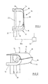
- the neck rest 10 shown in Figs. 1 and 2 has a guiding portion 12 and a supporting portion 14.
- the guiding portion 12 is provided with a horizontal portion 16 and a deforming portion 18 which is partially bent upwards, joins the horizontal portion 16, and extends approximately vertically at the end ("horizontal” and “vertical” mean the orientation of the designated portions when the neck rest is mounted on the back rest of an automobile seat that is not shown).
- the horizontal portion 16 has connected thereto neck rest rods 20 which are pushed into a socket (not shown) of a back (not shown) of an automobile seat.
- Sockets of this type in the form of neck rest sleeves or the like are generally known. Their configuration can be such as to receive the rods 20 merely in one position or also in various height positions, e.g. via respective latch positions of the rods 20 and sockets.
- the guiding portion 12 defines an accommodating channel 22.
- the supporting portion 14 has an upper horizontal holding section 24 which is of a relatively rigid design and has guiding rods 26 mounted at its underside.
- the guiding rods 26 are received by the hollow neck rest rods 20 (Fig. 2).
- the horizontal holding section 24 is joined by an elastically deformable portion 30 which engages the upper end of the accommodating channel 22.
- the deformable portion 30, for example, is an elastic strap of metal of plastic which can be guided within the accommodating channel 22 by providing the walls of the accommodating channel 22 with appropriate guide grooves (not shown).
- the deformable portion 30 accommodates an appropriate supporting pad which is not shown for reasons of simplicity here. It serves for absorbing the shock forces which occur when the head of the person sitting on the seat which is not shown strikes against the neck rest because of an abrupt acceleration.
- the supporting portion 14 can be adjusted in its height and be moved downwards with respect to the guiding portion 12. This causes the guiding rods 26 to move into the head rest rods 20 and latch positions (not shown) can be predetermined between these rods to maintain a relative position occupied between the components 12 and 14.
- the most downwardly lowered position is shown in Fig. 2. It has received therein the portion 30 substantially in the accommodating channel 22 of the guiding portion 12. While the portion 30 is pushed into in the accommodating channel 22 it will deform elastically. If it is necessary to push the lower end of the portion 30 into the accommodating channel 22 so far that this end has to be moved rightwards beyond the guiding rods 26 the lower end of the deformable portion 30 requires to be fitted with appropriate recesses to allow the adjustment described.
- the guiding rods 26 can be latched in the neck rest rods 20 at different height positions. However, it is also perceivable to vary the height of the supporting portions 14, using an adjustment mechanism. This is outlined by a adjustment cable (Bowden control cable) 30 which is connected to the guiding rods 26 and is operated by an actuation means 32.
- the actuation means 32 can be an electric drive, for example. It is also imaginable to perform a manual operation from the driver's seat by shifting a lever (not shown) or the like.
- the guiding portion is shown extending across the entire width of the neck rest. However, it can also extend over some part of its width only and can be arranged in place centrally, for example. While a strip of the supporting portion, i.e. portion 30, which is guided in the guiding portion undergoes deformation the remaining portions laterally therefrom unavoidably will be deformed as well so that a reduction in the height of the neck rest is achieved in any case.
Landscapes
- Engineering & Computer Science (AREA)
- Aviation & Aerospace Engineering (AREA)
- Transportation (AREA)
- Mechanical Engineering (AREA)
- Seats For Vehicles (AREA)
- Chair Legs, Seat Parts, And Backrests (AREA)
- Vehicle Step Arrangements And Article Storage (AREA)
Abstract
Description
Claims (8)
- Neck rest for the back rest of the seats of automobiles, in particular for the back seat, the neck rest including two supporting rods which are accommodated by sockets in the back rest, characterized in that a guiding portion (12) and a supporting portion (14) located above the guiding portion (12) are provided, with the supporting portion (14) being height adjustable relative to the guiding portion (12), the supporting portion (14) includes at least a horizontal holding section (24) provided with at least one guiding rod (26) and having a deformable portion extending downwardly and adapted to support an upholstering portion, the guiding rod (26) is accommodated by a hollow neck rest rod (20), in that the deformable portion (30) with the upholstering portion and an accommodating channel (22) of the supporting portion (12) being designed such that the deformable portion (30) is accommodated by an accommodating channel (22) more or less depending upon the height of the supporting portion (14).
- The neck rest of claim 1, wherein the holding portion (24) and the guiding portion (22) are substantially rigidly structured.
- The neck rest of claim 1 or 2, wherein the deformable portion (30) has an elastic portion which is connected to the upholstering portion and deforms upon displacement into the guiding portion (12).
- The neck rest of claim 1 or 2, wherein the deformable portion consists of a plurality of linked elements.
- The neck rest of claim 1, wherein the holding portion (24) is connected to an arc-shaped portion (28) through which it extends into the deformable portion (30).
- The neck rest of claim 1, wherein the horizontal portion (16) is joined by an arc-shaped portion which is connected to the deforming portion (18).
- The neck rest of claim 1, wherein at least one guiding rod (26) can be fixed in the associated neck rest rod (20) at varying elevated positions.
- The neck rest of claim 1, wherein electromechanical actuation means (33) are provided for the supporting portion (14).
Applications Claiming Priority (2)
| Application Number | Priority Date | Filing Date | Title |
|---|---|---|---|
| DE10334551A DE10334551B3 (en) | 2003-07-30 | 2003-07-30 | Head rest for the back rest of a car seat, especially a rear seat, comprises a guide part and a support part arranged above the guide part and adjustable in height relative to the guide part |
| DE10334551 | 2003-07-30 |
Publications (2)
| Publication Number | Publication Date |
|---|---|
| EP1502808A2 true EP1502808A2 (en) | 2005-02-02 |
| EP1502808A3 EP1502808A3 (en) | 2008-03-26 |
Family
ID=33483091
Family Applications (1)
| Application Number | Title | Priority Date | Filing Date |
|---|---|---|---|
| EP04014210A Withdrawn EP1502808A3 (en) | 2003-07-30 | 2004-06-17 | Neck rest for automobile seats, in particular rear seats |
Country Status (5)
| Country | Link |
|---|---|
| US (1) | US6942293B2 (en) |
| EP (1) | EP1502808A3 (en) |
| CA (1) | CA2472703C (en) |
| DE (1) | DE10334551B3 (en) |
| MX (1) | MXPA04007440A (en) |
Cited By (2)
| Publication number | Priority date | Publication date | Assignee | Title |
|---|---|---|---|---|
| US7429082B2 (en) | 2004-03-19 | 2008-09-30 | Alfmeier Prazision Ag Baugruppen Und Systemlosungen | Vehicle seat with a pivotally installed headrest |
| FR2927583A1 (en) * | 2008-02-19 | 2009-08-21 | Peugeot Citroen Automobiles Sa | Headrest for passenger seat of motor vehicle, has support surface constituted by lower and upper elements that are movable with respect to each other, where lower element is in form of male comb, and upper element is in form of female comb |
Families Citing this family (6)
| Publication number | Priority date | Publication date | Assignee | Title |
|---|---|---|---|---|
| WO2004062963A1 (en) | 2003-01-10 | 2004-07-29 | Alfmeier Präzision AG | Fastening device for the headrest of a vehicle seat |
| ATE421931T1 (en) | 2004-05-14 | 2009-02-15 | Alfmeier Praez Ag | VEHICLE SEAT WITH A HEADREST |
| ATE526199T1 (en) | 2005-04-08 | 2011-10-15 | Alfmeier Praez Ag | VEHICLE SEAT WITH LUMBAR SUPPORT |
| US7356744B2 (en) * | 2005-05-12 | 2008-04-08 | Pc-Doctor, Inc. | Method and system for optimizing testing of memory stores |
| DE102007005737B4 (en) | 2007-01-31 | 2010-06-10 | Alfmeier Präzision AG Baugruppen und Systemlösungen | Headrest system for a vehicle seat |
| CN110638244B (en) * | 2019-11-06 | 2024-05-17 | 广州铧世家具制造有限公司 | Headrest |
Family Cites Families (13)
| Publication number | Priority date | Publication date | Assignee | Title |
|---|---|---|---|---|
| DE2743609A1 (en) * | 1977-09-28 | 1979-04-05 | Egon Schneider | Adjustable head rest for vehicle seat - has transparent sheet stretched between adjustable rollers to ensure unobstructed view |
| US4420186A (en) * | 1979-07-02 | 1983-12-13 | Hans Kaufeld Gmbh & Co. | Convertible low-back, high-back upholstered furniture |
| US4657304A (en) * | 1986-06-06 | 1987-04-14 | Itt Corporation | Adjustable headrest |
| US4720146A (en) * | 1986-08-28 | 1988-01-19 | General Motors Corporation | Vehicle seat headrest apparatus and method |
| US6007154A (en) * | 1996-09-16 | 1999-12-28 | Illinois Tool Works Inc. | Four-way articulating headrest system for automotive seats |
| US5769489A (en) * | 1997-05-09 | 1998-06-23 | Dellanno; Ronald P. | Energy absorbing support for vehicular passengers |
| DE19722785C2 (en) * | 1997-05-30 | 2000-11-16 | Faure Bertrand Sitztech Gmbh | Backrest with a headrest which can be lowered into the backrest, in particular for motor vehicle seats |
| DE19756700C1 (en) * | 1997-12-19 | 1998-12-17 | Daimler Benz Ag | Adjustable vehicle seat |
| DE19800077B4 (en) * | 1998-01-02 | 2007-08-30 | Volkswagen Ag | Vehicle seat with a headrest |
| DE19927471A1 (en) * | 1999-06-16 | 2000-12-21 | Volkswagen Ag | Height-adjustable head restraint on backrest of motor vehicle seats has integrated net on roller, which is opened during crash to protect against flying loads |
| DE19944719C1 (en) * | 1999-09-17 | 2001-01-11 | Lear Corp Gmbh & Co Kg | Automobile passenger seat for 2-door vehicle has integrated headrest moved relative to backrest frame as seat is pivoted forwards for reducing overall length of backrest |
| DE10125758A1 (en) * | 2001-05-18 | 2002-11-21 | Volkswagen Ag | Car seat has head rest whose upper section slides down support rods into lower section which can then slide down second set of support rods into back rest |
| EP1284215A3 (en) * | 2001-08-13 | 2006-01-18 | Nissan Motor Co., Ltd. | Headrest apparatus for vehicle |
-
2003
- 2003-07-30 DE DE10334551A patent/DE10334551B3/en not_active Expired - Fee Related
-
2004
- 2004-06-17 EP EP04014210A patent/EP1502808A3/en not_active Withdrawn
- 2004-06-29 CA CA002472703A patent/CA2472703C/en not_active Expired - Fee Related
- 2004-07-13 US US10/889,022 patent/US6942293B2/en not_active Expired - Fee Related
- 2004-07-30 MX MXPA04007440A patent/MXPA04007440A/en active IP Right Grant
Cited By (2)
| Publication number | Priority date | Publication date | Assignee | Title |
|---|---|---|---|---|
| US7429082B2 (en) | 2004-03-19 | 2008-09-30 | Alfmeier Prazision Ag Baugruppen Und Systemlosungen | Vehicle seat with a pivotally installed headrest |
| FR2927583A1 (en) * | 2008-02-19 | 2009-08-21 | Peugeot Citroen Automobiles Sa | Headrest for passenger seat of motor vehicle, has support surface constituted by lower and upper elements that are movable with respect to each other, where lower element is in form of male comb, and upper element is in form of female comb |
Also Published As
| Publication number | Publication date |
|---|---|
| EP1502808A3 (en) | 2008-03-26 |
| US6942293B2 (en) | 2005-09-13 |
| CA2472703C (en) | 2008-03-18 |
| DE10334551B3 (en) | 2004-12-23 |
| MXPA04007440A (en) | 2005-02-03 |
| CA2472703A1 (en) | 2005-01-30 |
| US20050023878A1 (en) | 2005-02-03 |
Similar Documents
| Publication | Publication Date | Title |
|---|---|---|
| KR101432790B1 (en) | Longitudinally adjustable vehicle seat | |
| EP1138548B1 (en) | A headrest of adjustable height for a motor-vehicle seat | |
| US4350389A (en) | Safety headrest for a vehicle seat | |
| KR101736831B1 (en) | Automatic headrest | |
| US20110148171A1 (en) | Height adjustable headrest for an automobile seat backrest | |
| US8973994B2 (en) | Variable lumbar support assembly | |
| US9131777B2 (en) | Variable lumbar support assembly | |
| DE102016125738A1 (en) | Adjustable upper backrest module | |
| DE102016125740A1 (en) | Extended headrest attachment to a backrest module | |
| DE102016125739A1 (en) | Independent thigh supports | |
| EP2261075B1 (en) | Cushion mat assembly for use in a vehicle seat | |
| EP1502808A2 (en) | Neck rest for automobile seats, in particular rear seats | |
| CN101296819A (en) | Active head restraint | |
| KR20140058689A (en) | Height-adjustable head restraint for a vehicle seat and vehicle seat with a height-adjustable head restraint | |
| CN108725272B (en) | Foldable lifting mechanism for H-point lifting | |
| KR101559181B1 (en) | Seat cushion extension device | |
| JP4926434B2 (en) | Active headrest | |
| KR100811005B1 (en) | Car Slide Headrests | |
| JPH07165016A (en) | Seat belt guide | |
| KR100494550B1 (en) | Back support-structure for working together lumbarsupport-device for automobile | |
| CN216659684U (en) | Headrest assembly for seat and seat for vehicle | |
| EP1578638A1 (en) | Active headrest for a vehicle seat | |
| KR100195024B1 (en) | Headrest structure of car | |
| KR100330874B1 (en) | Control Type Headrest of Vehicle Seat | |
| EP1217492B1 (en) | Adjustable pedal for motor-vehicles |
Legal Events
| Date | Code | Title | Description |
|---|---|---|---|
| PUAI | Public reference made under article 153(3) epc to a published international application that has entered the european phase |
Free format text: ORIGINAL CODE: 0009012 |
|
| 17P | Request for examination filed |
Effective date: 20040701 |
|
| AK | Designated contracting states |
Kind code of ref document: A2 Designated state(s): AT BE BG CH CY CZ DE DK EE ES FI FR GB GR HU IE IT LI LU MC NL PL PT RO SE SI SK TR |
|
| AX | Request for extension of the european patent |
Extension state: AL HR LT LV MK |
|
| PUAL | Search report despatched |
Free format text: ORIGINAL CODE: 0009013 |
|
| AK | Designated contracting states |
Kind code of ref document: A3 Designated state(s): AT BE BG CH CY CZ DE DK EE ES FI FR GB GR HU IE IT LI LU MC NL PL PT RO SE SI SK TR |
|
| AX | Request for extension of the european patent |
Extension state: AL HR LT LV MK |
|
| AKX | Designation fees paid |
Designated state(s): DE ES FR GB IT |
|
| RAP1 | Party data changed (applicant data changed or rights of an application transferred) |
Owner name: ITW AUTOMOTIVE PRODUCTS GMBH & CO. KG |
|
| STAA | Information on the status of an ep patent application or granted ep patent |
Free format text: STATUS: THE APPLICATION IS DEEMED TO BE WITHDRAWN |
|
| 18D | Application deemed to be withdrawn |
Effective date: 20110104 |