The present invention generally relates to
image processing apparatuses, programs, computer-readable
recording media, and image processing methods.
A function called network scanner is known
that connects a digital copying machine or an image
reading apparatus to a network, scans an original image
by means of a scanner of the digital copying machine or
the image reading apparatus, and delivers read image
data to a terminal such as a computer connected to the
network.
For example, Japanese Laid-Open Patent
Application No. 2000-333026 proposes to provide an
expansion box based on the architecture of a general-purpose
computer system, accumulate in a hard disk
device (scan box) in the expansion box images (image
data) that are scanned by an image input part of an
image forming apparatus, and share image files in the
scan box among computers connected to a network.
Such a scan box function is used by following
a processing procedure as described below. First, scan
parameters such as resolution, tone (gradation),
magnification, a surface to be read, image size, and a
saving location are selected, and an original image is
read. Then, read image data are transferred to an image
processing part and image processing in accordance with
the scan parameters is performed. However, since
printing of the image data is not planned, it is
unnecessary to generate a data format of a printing
system, and color coordinate transformation from the RGB
system to the CMYK system, tone correction, and a
compression process of the image data are omitted. Then,
the image data subjected to the image processing are
transferred to the expansion box. In the expansion box,
the received image data are temporarily saved in the
scan box, which is assigned to a predetermined disk
region in the hard disk device. When all original
documents are accumulated, the image data are retrieved
from the scan box by a client of a network.
However, with the technique disclosed in
Japanese Laid-Open Patent Application No. 2000-333026,
in a case where the client selects, by means of an
operation part, scan parameters such as the image kind
mode, resolution, tone, magnification, a surface to be
read, image size, and saving location, an original
(manuscript) is scanned, read image data are transferred
to the image processing part and accumulated in the hard
disk after being subjected to image processing in
accordance with the scan parameters. Thus, it is
difficult or impossible to perform image format
conversion on the accumulated image data. Hence, in a
case where plural people desire to receive the image
data accumulated in the storage medium under different
image format conditions, there is a disadvantage in that
it is necessary to scan the image data again depending
on the desired condition of each client.
A general object of the present invention is
to provide an improved and useful image processing
apparatus, program, computer-readable storage medium,
and image processing method in which one or more of the
above-mentioned problems are eliminated.
Another and more specific object of the
present invention is to enable image data that are input
in a predetermined image kind mode and accumulated in a
storage device of an image processing apparatus to be
used for various applications.
Still another object of the present invention
is to enable the same image data to be received by
plural people in different image kind modes.
In order to achieve the above-mentioned
objects, according to one aspect of the present
invention, there is provided an image processing
apparatus that includes an image reading apparatus
reading an image of a manuscript and a printer engine
performing image formation on a medium based on image
data of the read image of the manuscript, and performs a
copying function in accordance with various image kind
modes, said image processing apparatus comprising:
Accordingly, the image data input in the first
image kind mode and accumulated in the storage device
are converted to the image data of the second image kind
mode in accordance with the processing condition, and
transmitted to the external instrument connected to the
image processing apparatus via the network. Hence, it
is possible for the external instrument to receive from
the image processing apparatus the image data whose
image kind mode is converted to a desired image kind
mode. Thus, it is possible to use the image data
accumulated in the storage device for various purposes.
In addition, since conversion of image kind mode is
performed on the image data that are already accumulated
in the storage device, it is possible for plural people
to receive the same image data in different image kind
modes.
Here, the image kind mode represents a mode
for performing optimum image processing in accordance
with a manuscript image (document image or photograph
image, for example). The image kind mode includes: a
"character mode" that clearly reproduces characters
written with a pencil or light characters (characters
written with thin ink, for example); a "photograph mode"
that finely reproduces photographs; and a "character and
photograph mode" that reproduces a manuscript including
a photograph and characters.
In an embodiment of the present invention, the
image data accumulated in the storage device by the
image accumulation part may be the image data generated
based on the image read by the image reading apparatus
and not subjected to image processing for copying.
Accordingly, the present invention may be
applied to, for example, change of the image kind mode
with respect to monochrome image data.
In an embodiment of the present invention, the
image data accumulated in the storage device by the
image accumulation part may be the image data used for
the image formation by the printer engine and subjected
to image processing for copying.
Accordingly, the present invention may be
applied to, for example, change of the image kind mode
with respect to color image data.
In an embodiment of the present invention, the
processing condition may be specified by the external
instrument.
Accordingly, irrespective of the image kind
mode at the time of a copying operation, it is possible
to perform conversion to a image kind mode in accordance
with the processing condition requested by the external
instrument, and it is possible to satisfy a requirement
related to the image kind mode required by the external
instrument.
In an embodiment of the present invention, the
external instrument, which is a transmission destination
of the image data of the second image kind mode
subjected to the conversion by the data format
conversion part in accordance with the processing
condition, may be specified by an operation part
provided to the image processing apparatus.
Accordingly, irrespective of the image kind
mode at the time of a copying operation, it is possible
to perform conversion to an image kind mode in
accordance with the processing condition requested by
means of the operation part provided to the image
processing apparatus, and it is possible to specify by
means of the operation part provided to the image
processing apparatus an external instrument that is the
transmission destination of the image data subjected to
the conversion to the requested image kind mode. Hence,
it is possible to satisfy a requirement related to the
image kind mode required with respect to the external
instrument.
In an embodiment of the present invention, the
data format conversion part may include a filtering part
adjusting the intensity of the image data and a γ
process part adjusting the concentration characteristics
of the image data, and
the image data input in the first image kind
mode may be converted to the image data of the second
image kind mode by performing processes in the filtering
part and the γ process part by selecting coefficients
in accordance with the processing condition.
Accordingly, it is possible to positively
convert the image kind mode of image data from the first
image kind mode to the second image kind mode.
In an embodiment of the present invention, the
data format conversion part may include a resolution
conversion part that converts the resolution of the
image data accumulated in the storage device by the
image accumulation part.
Accordingly, since it is possible to convert
image data to image data having a desired resolution, it
is possible to satisfy the data contents required by the
external instrument.
In an embodiment of the present invention, the
data format conversion part may include a halftone
process part that converts the tone level of the image
data accumulated in the storage device by the image
accumulation part.
Accordingly, since it is possible to convert
image data to image data having a desired tone level, it
is possible to satisfy the data contents required by the
external instrument.
In an embodiment of the present invention, the
data format conversion part may include a compression
part that converts the file format of the image data
accumulated in the storage device by the image
accumulation part.
Accordingly, since it is possible to convert
image data to image data of a desired file format, it is
possible to satisfy the data contents required by the
external instrument.
Additionally, according to another aspect of
the present invention, there is provided a computer-readable
program controlling an image processing
apparatus that includes an image reading apparatus
reading an image of a manuscript and a printer engine
performing image formation on a medium based on image
data of the read image of the manuscript, and performs a
copying function in accordance with various image kind
modes, said program causing a computer to carry out:
Accordingly, the image data input in the first
image kind mode and accumulated in the storage device
are converted to the image data of the second image kind
mode in accordance with the processing condition, and
transmitted to the external instrument connected to the
image processing apparatus via the network. Hence, it
is possible for the external instrument to receive from
the image processing apparatus the image data whose
image kind mode is converted to a desired image kind
mode. Thus, it is possible to use the image data
accumulated in the storage device for various purposes.
In addition, since conversion of image kind mode is
performed on the image data that are already accumulated
in the storage device, it is possible for plural people
to receive the same image data in different image kind
modes.
In an embodiment of the present invention, the
image data accumulated in the storage device by the
image accumulation function may be the image data
generated based on the image read by the image reading
apparatus and not subjected to image processing for
copying.
Accordingly, the present invention may be
applied to, for example, change of the image kind mode
with respect to monochrome image data.
In an embodiment of the present invention, the
image data accumulated in the storage device by the
image accumulation function may be the image data used
for the image formation by the printer engine and
subjected to image processing for copying.
Accordingly, the present invention may be
applied to, for example, change of the image kind mode
with respect to color image data.
In an embodiment of the present invention, the
processing condition may be specified by the external
instrument.
Accordingly, irrespective of the image kind
mode at the time of a copying operation, it is possible
to perform conversion to an image kind mode in
accordance with the processing condition requested by
the external instrument, and it is possible to satisfy a
requirement related to the image kind mode required by
the external instrument.
In an embodiment of the present invention, the
external instrument, which is a transmission destination
of the image data of the second image kind mode
subjected to the conversion by the data format
conversion part in accordance with the processing
condition, may be specified by an operation part
provided to the image processing apparatus.
Accordingly, irrespective of the image kind
mode at the time of a copying operation, it is possible
to perform conversion to an image kind mode in
accordance with the processing condition requested by
means of the operation part provided to the image
processing apparatus, and it is possible to specify by
means of the operation part provided to the image
processing apparatus an external instrument that is the
transmission destination of the image data subjected to
the conversion to the image kind mode. Hence, it is
possible to satisfy a requirement related to the image
kind mode required with respect to the external
instrument.
In an embodiment of the present invention, the
data format conversion function may include a filtering
function of adjusting the intensity of the image data
and a γ process function of adjusting the concentration
characteristics of the image data,
wherein the image data input in the first
image kind mode may be converted to the image data of
the second image kind mode by causing the computer to
carry out the filtering function and the γ process
function by selecting coefficients in accordance with
the processing condition.
Accordingly, it is possible to positively
convert the image kind mode of image data from the first
image kind mode to the second image kind mode.
In an embodiment of the present invention, the
data format conversion function may cause the computer
to carry out a resolution conversion function that
converts a resolution of the image data accumulated in
the storage device by the image accumulation function.
Accordingly, since it is possible to convert
image data to image data having a desired resolution, it
is possible to satisfy the data contents required by the
external instrument.
In an embodiment of the present invention, the
data format conversion function may cause the computer
to carry out a halftone process function that converts
the tone level of the image data accumulated in the
storage device by the image accumulation function.
Accordingly, since it is possible to convert
image data to image data having a desired tone level, it
is possible to satisfy the data contents required by the
external instrument.
In an embodiment of the present invention, the
data format conversion function may cause the computer
to carry out a compression function that converts the
file format of the image data accumulated in the storage
device by the image accumulation function.
Accordingly, since it is possible to convert
image data to image data of a desired file format, it is
possible to satisfy the data contents required by the
external instrument.
Additionally, according to another aspect of
the present invention, there is provided a computer
readable storage medium storing one of the programs as
mentioned above.
Accordingly, by causing a computer to read and
execute the program stored in the storage medium, it is
possible to obtain effects similar to those obtained by
the programs as mentioned above.
Additionally, according to another aspect of
the present invention, there is provided an image
processing method to be used in an image processing
apparatus that includes an image reading apparatus
reading an image of a manuscript and a printer engine
performing image formation on a medium based on image
data of the read image of the manuscript, and performs a
copying function in accordance with various image kind
modes, said image processing method comprising the steps
of:
Accordingly, the image data input in the first
image kind mode and accumulated in the storage device
are converted to the image data of the second image kind
mode in accordance with the processing condition, and
transmitted to the external instrument connected to the
image processing apparatus via the network. Hence, it
is possible for the external instrument to receive from
the image processing apparatus the image data whose
image kind mode is converted to a desired image kind
mode. Thus, it is possible to use the image data
accumulated in the storage device for various purposes.
In addition, since conversion of image kind mode is
performed on the image data that are already accumulated
in the storage device, it is possible for plural people
to receive the same image data in different image kind
modes.
Other objects, features and advantages of the
present invention will become more apparent from the
following detailed description of exemplary embodiments
when read in conjunction with the following drawings, in
which:
DETAILED DESCRIPTION OF THE PREFERRED EMBODIMENTS
Referring to FIGS. 1 through 12, a description
is given below of a first embodiment of the present
invention. In this embodiment, a digital color copying
machine, which is a multi-functional apparatus having a
copying function, a facsimile (FAX) function, a printer
function, and a function of delivering an input image
(read original image and an image that is input by the
printer or FAX function) is used as an image processing
apparatus.
(1. Description of Digital Color Copying Machine 100)
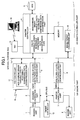
FIG. 1 is a block diagram schematically
showing the system structure of a digital color copying
machine 100 according to this embodiment. The digital
color copying machine 100 shown in FIG. 1 is broadly
classified into an engine part 101 and a printer
controller part 102. The engine part 101 is controlled
by an engine controller 12, and the printer controller
part 102 is controlled by a printer controller 4. The
digital color copying machine 100 also includes a FAX
controller 13 in the engine part 101, thereby
controlling the FAX function of the digital color
copying machine 100 and transmitting/receiving image
data to/from a predetermined network such as a PSTN
(Public Switched Telephone Network). The digital color
copying machine 100 includes an image data delivering
function in addition to the copying function, the FAX
function, and the printer function, which functions are
realized by operations of the engine part 101 and the
printer controller part 102.
As for elements used for the copying function,
the digital color copying machine 100 includes: a
reading unit 1 that is an image reading apparatus
reading an original (manuscript) as color image data; a
scanner correction part 2 that performs image processing
on image data read by the reading unit 1; a color multi-level
data fixed-length compression part 3 that
compresses color multi-level data output from the
scanner correction part 2, and a HDD (Hard Disk Drive) 5
that is a storage device accumulating compressed data.
In addition, as for elements used for the FAX
function, the digital color copying machine 100
includes: the FAX controller 13 that is connected to the
PSTN and handles transmission and reception of a FAX
signal; and a monochrome binary variable-length
reversible compression data decompression part that is
provided in the FAX controller 13 and decompresses the
received compressed FAX data into original data.
Further, as for elements used for the printer
function, the digital color copying machine 100
includes: a NIC (Network Interface Controller) 14 for
communicating with an external PC (Personal Computer) 19,
which is an external instrument connected to a network
such as a LAN (Local Area Network); and the printer
controller 4 that performs raster image processing (RIP)
in accordance with a print command from the external PC
19 via the NIC 14, and performs compression dedicated to
data subjected to the RIP.
Additionally, as for elements used for the
image data delivering function, the digital color
copying machine 100 includes an image format conversion
unit 10 (which is further described below) that
functions as data format conversion means for converting
the data generated when using each of the above-mentioned
functions and accumulated in the HDD 5 into a
data format suitable for a terminal (in this embodiment
the external PC 19), which is a transfer destination.
When printing out (performing an image
formation process on) image data generated by each of
the above-mentioned functions, the compressed data
accumulated in the HDD 5 are used. Thus, in order to
decompress the accumulated compressed data into the
original data, a color multi-level data fixed-length
decompression part 6 is provided for the copying
function, and a monochrome binary variable-length
reversible compression data decompression part and a
color variable-length reversible compression data
decompression part are provided in the printer
controller 4 for the FAX and printer functions. The
engine part 101 includes as means for performing an
image forming process a printer correction part 7 that
performs correction on decompressed data, and an imaging
unit 9 that is a printer engine. The imaging unit 9
forms and outputs an image onto a medium such as a
transfer paper. The imaging unit 9 may use various
printing systems such as electrophotographic systems,
inkjet printing systems, sublimation dye transfer
printing systems, silver photography systems, direct
thermal printing systems, and thermofusible transfer
systems.
The printer controller 4 is structured by a
microcomputer including a CPU (Central Processing Unit)
that centrally controls each part, a ROM (Read Only
Memory) that is a storage medium in which fixed data
such as an activation program executed by the CPU are
written, and a semiconductor memory 11 that is a RAM
(Random Access Memory) in which variable data such as
work data are written in a manner allowing updating.
The HDD 5 stores an application program executed by the
CPU. That is, when a user turns ON the digital color
copying machine 100, the CPU activates the activation
program in the ROM, the application program is read from
the HDD 5 into the semiconductor memory 11, and the
application program is activated. Since the CPU is
operated in accordance with the application program, the
printer controller 4 controls the operation of the
printer controller part 102. As for the application
program stored in the HDD 5, the application program is
recorded on an optical information storage medium such
as a CD-ROM and a DVD-ROM or a magnetic medium such as a
flexible disk, and the recorded application program is
installed to the HDD 5. Hence, a portable storage
medium, for example, an optical information storage
medium such as a CD-ROM and a magnetic medium such as a
flexible disk, may be the storage medium storing the
application program. Further, the application program
may be, for example, downloaded from the outside via a
network and installed to the HDD 5.
(2. Description of Various Functions of Digital Color
Copying Machine 100).
A more detailed description is given below of
the copying function and the image data delivering
function together with the operations thereof among the
various functions (the copying function, the printer
function, the FAX function, and the image data
delivering function) of the digital color copying
machine 100 structured by the above-mentioned elements.
(2-1. Copying Function)
First, referring to FIG. 2, a description is
given below of processes at the time when the copying
function is used. When reading an original, the
original set on an original table is read by the reading
unit 1, and data subjected to color separation and
separated into R (red), G (green) and B (blue) are sent
to the scanner correction part 2.
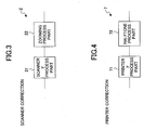
FIG. 3 is a block diagram showing the internal
structure of the scanner correction part 2. As shown in
FIG. 3, the scanner correction part 2 includes a scanner
γ process part 21 and a zooming process part 22. The
scanner γ process part performs a scanner γ process,
and the zooming process part 22 performs a zooming
process.
Eight-bit image data after zooming are
compressed and converted to n-bit (n ≦ 8) data by the
color multi-level data fixed-length compression part 3.
The image data compressed by the color multi-level
data fixed-length compression part 3 are sent to
the printer controller 4 via the general-purpose bus I/F
15. The printer controller 4 accumulates the sent data
in the semiconductor memory 11.
The accumulated data are written to the HDD 5
as required. The reason for accumulating the data in
the HDD 5 is to avoid reading an original again even if
paper jams at the time of printing and printing does not
end normally, and to perform electronic sorting. In
addition to this, recently, the digital color copying
machine 100 is further provided with a function of
accumulating data of read originals and outputting the
data again when necessary. Also, this embodiment using
the HDD 5 may be used for such a copy server function.
Here, image accumulating means is realized.
Accordingly, the image data accumulated in the
HDD 5 of this embodiment are read images (image data)
that are not subjected to image processing for copying,
such as color coordinate transformation from the RGB
system to the CMYK system, tone (gradation) correction,
and a compression process. The image data accumulated
in the HDD of this embodiment are, for example,
monochrome image data.
Whatever the case may be, printing is
performed by using the accumulated data in the HDD 5.
Thus, when printing is performed, the compressed image
data in the HDD 5 are temporarily developed (held) in
the semiconductor memory 11, sent to the engine part 101
via the general-purpose bus 15, and converted again into
8-bit image data by the color multi-level data fixed-length
decompression part 6 of the engine part 101.
The decompressed data are sent to the printer
correction part 7. FIG. 4 is a block diagram showing
the internal structure of the printer correction part 7.
As shown in FIG. 4, the printer correction part 7
includes a printer γ process part 71 and a halftone
process part 72. The printer γ process part 71
performs a printer γ correction process. The halftone
process part 72 performs a halftone process
corresponding to the imaging unit 9, which is provided
in a subsequent stage, and transfers the data to the
imaging unit 9 as data used for imaging. Then, the data
are output on transfer paper.
(2-2. Image Data Delivering Function)
In the system as mentioned above where input
image data are temporarily accumulated in the HDD 5 as
compression data and thereafter the accumulated data are
retrieved from the HDD 5 and used, delivering is
performed by using the accumulated data in the HDD 5 in
the image data delivering function.
FIG. 5 is a block diagram showing the flow of
delivering data at the time of delivering image data by
one-dot chain lines. As shown in FIG. 5, the external
PC 19, which becomes a client, determines a capture
condition (processing condition) for receiving
(capturing) the image data from the digital color
copying machine 100, and requests the digital color
copying machine 100 for the image data by offering the
capture condition.
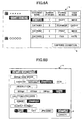
FIGS. 6A and 6B show examples of a display
screen image at the time when the application program
for receiving (capturing) the image data from the
digital color copying machine 100 is activated in the
external PC 19. An image data selection screen "a" as
shown in FIG. 6A is displayed in the external PC 19.
Thus, it is possible to view the image data accumulated
in the HDD 5 of the digital color copying machine 100 by
means of the external PC 19. A user who operates the
external PC 19 selects image data in the image data
selection screen "a". In FIG. 6A, "DATA000", which is
indicated by hatching, is selected. When a capture
condition button "b" is operated in a state where the
desired image data are selected, a capture condition
selection screen "c" as shown in FIG. 6B is displayed on
the external PC 19.
In the capture condition selection screen "c",
it is possible to select conditions for capturing image
data, such as the image kind mode, resolution, a
halftone process, and output format. As for the image
kind mode, it is possible to select each of the modes of
"character", "character and photograph", "photograph"
and "OCR". As for the resolution, it is possible to
select 600 dpi, 400 dpi, 300 dpi or 200 dpi. As for the
halftone process, it is possible to select binary or
multi-level. As for the output format, is it possible
to select TIFF, JPEG or JPEG 2000. In the capture
condition selection screen "c" as mentioned above, the
user operating the
external PC 19 selects the conditions
for capturing image data, such as the image kind mode,
the resolution, the halftone process, and the output
format. In FIG. 6B, as indicated by hatching, the
following conditions are selected as the capture
conditions.
| image kind mode | photograph |
| resolution | 200 dpi |
| halftone process | multi-level |
| output format | JPEG |
When a capture button "d" is operated in such a state
where the capture conditions are selected as mentioned
above, the selected capture conditions are supplied to
the
printer controller 4 of the digital
color copying
machine 100.
The printer controller 4 that has received the
capture conditions refers to the attributes of the image
data accumulated in the HDD 5, and issues an instruction
to the image format conversion unit 10 as to what kind
of image processing is to be performed.
Upon reception of the instruction from the
printer controller 4, the image format conversion unit
10 performs an imaging process (for example, in a case
where the image kind mode is the photograph mode, a γ
process for the photograph mode and filtering for the
photograph mode) in accordance with the selected capture
conditions so as to convert the image format of the
image data into the image format desired by the user,
and transmits the image data to the external PC 19.
Here, image data delivering means is realized.
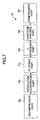
FIG. 7 is a block diagram showing the
structure of the image format conversion unit 10. As
shown in FIG. 7, upon reception of the instruction from
the printer controller 4, the image format conversion
unit 10, which converts the data format of delivering
image data, performs functions corresponding to a
decompression part 10a, a resolution conversion part 10b,
a filtering part 10c, a γ process part 10d, a halftone
process part 10e, and a compression part 10f. The
decompression part 10a decompresses the image data
compressed and accumulated in the HDD 5. The
decompressed image data are subjected to resolution
conversion and converted to a predetermined resolution
by the resolution conversion part 10b. Then, the image
data are subjected to filtering by the filtering part
10c. The filtering process adjusts the intensity of the
image data. The γ process part 10d performs adjustment
of concentration characteristics of the image data. The
halftone process part 10e quantizes the multi-level data
into binary image data. Then, the compression part 10f
performs compression coding on the image data according
to a predetermined compression coding format. Then, the
image data are transmitted to the external PC 19. In
the aforementioned manner, the image data of a first
data format accumulated in the HDD 5 are output as the
image data of a second data format by changing the data
format.
A description is given below of conversion of
data format by the resolution conversion part 10b. When
the resolution of the image data accumulated in the HDD
5 is different from the resolution required by a
terminal that is a delivering destination, the
resolution conversion part 10b converts the resolution
of the image data to be delivered to a specified
resolution, thereby enabling the image data to be used
by the terminal such as the external PC 19.
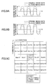
FIGS. 8A, 8B and 8C are diagrams for
explaining a resolution conversion function of the
resolution conversion part 10b. As shown in FIG. 8A,
the resolution conversion part 10b includes conversion
process blocks, i.e., a main scan direction resolution
conversion block 104 and a sub-scan direction resolution
conversion block 105 in this order from the input side.
As shown in FIG. 8B, the main scan direction resolution
conversion block 104 includes FFs 106 corresponding to
pixels in the main scan direction and an interpolation
pixel calculation part 107. As shown in FIG. 8C, the
sub-scan direction resolution conversion part 105
includes sub-scan line accumulation memory 108
corresponding to a predetermined number of lines and an
interpolation pixel calculation part 109. It should be
noted that FIGS. 8A through 8C show a case where target
pixel data are multi-level data and conversion is
performed according to a method capable of converting
the resolutions in the main scan direction and the sub-scan
direction of image data into arbitrary resolutions.
In the resolution conversion part 10b shown in
FIGS. 8A through 8C, in order to convert input multi-level
data to the number of data of the specified
resolution (dpi), the interpolation pixel calculation
part 107 of the main scan direction resolution
conversion block 104 performs pixel interpolation in the
main scan direction on the input multi-level data. For
example, the most-adjacent pixel displacement method,
adjacent 2-pixel weighted average method, or cubic
function convolution method, which are commonly used,
may be applied to calculate pixel data values to be
interpolated. The sub-scan direction resolution
conversion block 105 calculates the data value of lines
to be interpolated by the interpolation pixel
calculation part 109 with respect to the multi-level
data subjected to resolution conversion in the main scan
direction based on reference pixel data in the sub-scan
direction accumulated in the sub-scan line accumulation
memory 108, which includes line memories each capable of
accumulating data subjected to the main scan direction
resolution conversion amounting to one line. Similar to
the case of pixel interpolation in the main scan
direction, the most-adjacent pixel displacement method,
adjacent 2 pixel weighted average method, or cubic
function convolution method, for example, may be applied
to calculation in the interpolation pixel calculation
part 109.
Accordingly, since it is possible to convert
image data to image data of a desired resolution, it is
possible to satisfy data contents required by an
external instrument.
A description is given below of conversion of
a data format by the filtering part 10c. Filtering
modulates the MTF of image data. There are two kinds of
filtering: filtering that increases the MTF value of
original image data thereby enhancing edges of the
image; and filtering that decreases the MTF value of the
original image data thereby smoothening the image.
When increasing the MTF of image data, a
process that enhances the curve of image frequency is
performed as shown in FIG. 9A. In FIG. 9A, the image
frequency of original image data is indicated by a
continuous line, and the image frequency after filtering
is indicated by a dotted line. In addition, the
vertical axis represents the dynamic range of image data
(image density), and the horizontal axis represents'the
raster format reference of image data (the way to refer
to the raster-format image data).
Similarly, when smoothening the MTF of image
data, a process of relaxing the curve of image frequency
is performed as shown in FIG. 9B. In an actual process,
two-dimensional image data are handled in units of lines
while assuming the raster direction of the image data as
a line direction (x direction) and the direction
perpendicular to the raster direction as a y direction,
and the value of a target pixel is calculated based on
the values of pixels surrounding the target pixel.
FIG. 9C shows the 5 x 5 surrounding pixels,
having the target pixel in the center thereof, with
symbols while assuming the target pixel as Xn,m.
When increasing the MTF of image data,
differential coefficients (hereinafter referred to as
"matrix coefficients") corresponding to respective
pixels surrounding the target pixel are prepared. When
the matrix coefficients are represented with symbols in
the same format as the symbols of the surrounding pixels,
i.e., Am-2, n-2, Am-2, n-1, ..., Am, n, Am+2, n+1, Am+2, n+2, then
the value Y of the target pixel after the filtering for
increasing the MTF of the image data can be represented
by the following formulas.
B = (Xm-2, n-2 x Am-2, n-2) + (Xm-2, n-1 x Am-2, n-1)
+ ... + (Xm+2, n+2 x Am+2, n+2)
D = B x C
Y = D + Xn, m
The formula (1) performs matrix multiplication on the
image data and the matrix coefficients obtained by using
the differential coefficients. The value of B obtained
by the formula (1) is an enhancing component of the
image to be enhanced by the filtering. The formula (2)
arbitrarily amplifies and deamplifies the enhancing
component. The enhancing value to be enhanced by the
filtering obtained by the formula (2) is added to the
value of the target pixel, thereby calculating the final
value of the target pixel (the formula (3)). By
converting all pixels of the image data with the above-mentioned
formulas, the MTF of the image data is
increased.
When smoothening image data, the target pixel
and the surrounding pixels are added and divided by the
number of pixels E, thereby obtaining the average value
of the target value and the surrounding pixels. By
converting all pixels of the image data with such a
formula, the image data are smoothened. When, in order
to adjust the degree of smoothening, the target pixel
and the surrounding pixels are not averaged by assuming
the weight thereof as equivalent, i.e., each pixel is
assumed to have a different weight, it is possible to
adjust the value Y of the target value by substituting
the matrix coefficients for arbitrary integers.
Y = (Xm-2, n-2 x Am-2, n-2) + (Xm-2, n-1 x Am-2, n-1)
+ ... + (Xm+2, n+2 x Am+2, n+2)/E
With the above-mentioned processes, the filtering part
10c can realize the filtering function capable of
modulating an MTF with respect to multi-level image data.
Hence, if an original image is an image mainly including
characters, the quality of the image is improved by
enhancing the MTF. On the other hand, when an original
image is an image mainly including images, the quality
of the image is improved by smoothening the image to
some extent. In the aforementioned manner, by selecting
the filtering coefficient depending on the kind of an
image, it is possible to obtain a high quality image.
A description is given below of conversion of
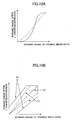
a data format by the γ process part 10d. The γ process
part 10d varies the concentration gradient and
concentration characteristics of an image. As shown in
FIG. 10A, if the continuous line in FIG. 10A represents
a γ conversion table, the values corresponding to
original data (horizontal axis) are converted to the
value of image data (vertical axis) after γ conversion.
By varying the curve of the γ conversion table, it is
possible to convert image data to image data having a
desired concentration distribution. For example, if the
γ conversion table as indicated by the dotted line in
FIG. 10A is used, compared to the γ conversion table
indicated by the continuous line, it is possible to
convert image data to image data (after γ conversion)
having a relaxed concentration gradient. It should be
noted that, in FIG. 10A, the concentration is increased
in the direction indicated by the arrows in FIG. 10A.
A description is given below of a method for
creating a γ conversion table with reference to a
linear γ conversion table (a continuous line (a))
extending in a 45-degree direction from the origin.
When increasing/decreasing the entire
concentration of an image without changing the
concentration characteristics, the γ conversion table
may be moved in parallel as indicated by the continuous
lines (b) in FIG. 10B. When changing the concentration
gradient, the slope of the γ conversion table may be
varied as indicated by the dotted lines (c) in FIG. 10B.
When varying the concentration characteristics, by
varying the curve of a γ conversion table that can be
represented with a continuous curved line such as shown
in FIG. 10A, it is possible to obtain desired
concentration characteristics.
In the aforementioned manner, the γ process
part 10d can realize the γ conversion process function
capable of varying the concentration gradient and
concentration characteristics of image data. Hence, it
is possible to obtain a high quality image by selecting
a γ curve depending on the kind of an image.
A description is given below of conversion of
a data format by the halftone process part 10e. The
halftone process part 10e binarizes multi-level image
data by performing a halftone process thereon. The
halftone process is a process that quantizes multi-level
image data to binary data or data having a small tone
level close to binary. There are various methods for
performing the halftone process. Here, a description is
given of the simple quantization method, the dither
method, and the error diffusion method, which are
generally used. However, it is assumed for convenience
that the tone (gradation) level for quantization is
binary.
The simple quantization method converts the
tone level of image data to binary while using an
arbitrary value in a dynamic range of multi-level image
data as a threshold value. For example, when quantizing
multi-level image data having the dynamic range of 0-255,
i.e., 256 tones, to image data represented by using
combinations of 0 and 1, if the threshold value is 128,
the quantization value for image data having a dynamic
range value 100 is 0, and the quantization value for
_image data having a dynamic range value 200 is 1.
The dither method performs binarization for
each pixel by using a threshold value matrix 81 as shown
in FIG. 11B and applying the threshold value matrix 81
to image data 82 such that 1 threshold value corresponds
to 1 pixel. When the threshold values in the threshold
value matrix 81 are varied within the dynamic range of
the image data 82, the resolution of an image may be
degraded. However, it is possible to reproduce an
intermediate concentration even for image data having
two tones.
Similar to the simple quantization method, the
error diffusion method performs conversion into two
tones by using an arbitrary threshold value. In the
error diffusion method, quantization error generated in
quantization are accumulated, and quantization with
respect to a target pixel under processing is performed
by taking into consideration the determined errors in
the surrounding pixels that have already been subjected
to quantization in raster order. Thereby, the error
diffusion method performs,a halftone process that aims
for minimizing errors due to quantization in image data
in total.
The errors generated in quantization are
represented in the case as follows. In a case where
multi-level image data having the dynamic range of 0-255,
i.e., 256 tones, are converted to image data represented
by using combinations of 0 and 1, the quantization value
of image data having a dynamic range value 100 is 0.
However, though the image data includes intermediate
concentration information, i.e., 100, the information is
handled as the lowest value 0. Thus, the intermediate
concentration information of the image data is lost.
Hence, the quantization error of the image data is "100
= 100 - 0" (the lowest value of the dynamic range). In
addition, the quantization value of image data having a
dynamic range value 200 is 1. In this case, though the
image data includes intermediate concentration
information, i.e., 200, the information is handled as
the highest value 1. Thus, the quantization error of
the image data is "-55 = 200 - 255" (the highest value
of the dynamic range).
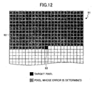
After quantization is performed on each pixel,
if such quantization error values are accumulated as
data different from image data, as shown in FIG. 12,
considering that image data 91 are processed in raster
order, the errors in quantization are already determined
and accumulated with respect to hatched pixels 92. In
the error diffusion method, by performing conversion
into two tones after adding the average of the
determined error values of the pixels surrounding a
target pixel 93 to the value of the target pixel 93, it
is possible to reduce the lack of intermediate
concentration information, which is caused by the
quantization errors, in image data in total.
With the above-mentioned methods, the halftone
process part 10e can perform a binarization process on
multi-level image data. In the aforementioned manner,
by reducing the amount of data and selecting the
halftone process depending on the kind of an image, it
is possible to obtain a high quality image.
Accordingly, since it is possible to convert
image data to image data having a desired tone value, it
is possible to satisfy the data contents required by an
external instrument.
A description is given below of a specific
process performed in a case where image data are output
to, for example, the
external PC 19. A case is assumed
where the following conditions are selected as the
capture conditions and delivered to the
printer
controller 4.
| image kind mode | photograph |
| resolution | 200 dpi |
| halftone process | multi-level |
| output format | JPEG |
In this case, the image format conversion unit
10 performs image processing by setting the processing
conditions (parameters) as required.
In this case, a resolution conversion
parameter value used for resolution conversion in the
resolution conversion part 10b is determined from the
resolution requested by the user and the resolution
(here, 600 dpi) of image data accumulated in the HDD 5.
That is, resolution conversion from 600 dpi to 200 dpi
is performed.
In the filtering part 10c and the γ process
part 10d following the resolution conversion part 10c,
coefficients corresponding to the requirement from the
external PC 19 are selected. In this case, since the
image kind mode requested by the user is the photograph
mode, the coefficient for the photograph mode is
selected in each of the filtering part 10c and the γ
process part 10d.
In addition, since "multi-level" is selected
for the halftone process, the halftone process part 10e
does not perform a process.
In the compression part 10f following the
halftone process part 10e, a conversion process to the
JPEG file format is performed. Accordingly, since it is
possible to convert image data to image data having a
desired file format, it is possible to satisfy the data
contents required by an external instrument.
In the aforementioned manner, it is possible
for the external PC 19 to receive (capture) from the
digital color copying machine 100 the image data (read
image that is not subjected to imaging processes for
copying such as color coordinate conversion from the RGB
system to the CMYK system, tone correction, and a
compression process of image data) accumulated in the
HDD 5 of the digital color copying machine 100 in a
state where the image data are converted to the image
format according to the capture conditions supplied from
the external PC 19.
Here, image data input in a first image kind
mode and accumulated in a storage device are converted
to image data of a second image kind mode in accordance
with the processing conditions, and transmitted to an
external instrument via a network. Thus, it is possible
for the external instrument to receive from an image
processing apparatus image data whose image kind mode is
converted to a desired image kind mode. Hence, it is
possible to use the image data accumulated in the
storage device for various purposes. Additionally,
since conversion of image kind mode is performed on the
image data that are already accumulated in the storage
device, it is possible for plural people to receive the
same image data in different image kind modes.
Further, since it is possible to perform
conversion to the image kind mode in accordance with
processing conditions requested by the external
instrument irrespective of the image kind mode in a
copying operation, it is possible to satisfy
requirements related to the image kind mode by the
external instrument.
Referring to FIGS. 13 through 15, a
description is given below of a second embodiment of the
present invention. In the description of the second
embodiment, those parts that are the same as those
corresponding parts in the description of the first
embodiment are designated by the same reference numerals,
and a description thereof is omitted. In the first
embodiment, the image data accumulated in the HDD 5 are
read image data that are not subjected to image
processing for copying. On the other hand, in the
second embodiment, the image data accumulated in the HDD
5 are read image data that are subjected to the image
processing for copying. In this point, the second
embodiment differs from the first embodiment.
(1. Description of Various Functions of Digital Color
Copying Machine 100)
A detailed description is given below of the
copying function and the image data delivering function
together with the operations thereof among the various
functions (the copying function, the printer function,
the FAX function, and the image data delivering
function) of the digital color copying machine.
(1-1. Copying Function)
A description is given below of processes
performed when using the copying function in this
embodiment. As described above with reference to FIG. 2,
when reading an original (manuscript), the original set
to the original table is read by the reading unit 1, and
data subjected to color separation and separated into R
(red), G (green) and B (blue) are sent to the scanner
correction part 2.
FIG. 13 is a block diagram showing the
internal structure of the scanner correction part 2
according to this embodiment. As shown in FIG. 13, the
scanner correction part 2 includes a printer γ process
part 23 and a halftone process part 24 in addition to
the scanner γ process part 21 and the zooming process
part 22, which are described above in the first
embodiment. The scanner γ process part performs a
scanner γ process, and the zooming process part 22
performs a zooming process. The scanner correction part
2 performs the scanner γ process in the scanner γ
process part 21, the zooming process in the zooming
process part 22, a printer γ process in the printer γ
process part 23, and a tone process in the halftone
process part 24.
Multi-level or binary image data subjected to
the tone process are compressed and converted to data of
n bits (n ≦ 8) by the color multi-level data fixed-length
compression part 3. It should be noted that
binary image data pass through the path of non-compression.
The image data compressed by the color multi-level
data fixed-length compression part 3 are
transmitted to the printer controller 4 via the general-purpose
bus I/F 15. The printer controller 4 includes
the semiconductor memory 11 and the accumulated
transmitted data therein.
The accumulated data are written to the HDD 5
as required. The reason for accumulating the data in
the HDD 5 is to avoid reading an original again even if
paper jams at the time of printing and printing does not
end normally, and to perform electric sorting. In
addition to this, recently, the digital color copying
machine 100 has been further provided with the function
of accumulating data of read originals and outputting
the data again when necessary. Also in this embodiment,
the HDD 5 may be used for such a copy server function.
Accordingly, the image data accumulated in the
HDD 5 in this embodiment are read image data that are
subjected to the image process for copying such as color
coordinate conversion from the RGB system to the CMYK
system, tone correction, and a compression process of
image data. For example, the image data may be color
image data.
Whatever the case may be, printing is
performed by using the accumulated data in the HDD 5.
Thus, when printing is performed, the compressed image
data in the HDD 5 are temporarily developed (held) in
the semiconductor memory 11, sent to the engine part 101
via the general-purpose bus 15, and converted to multi-level
or binary image data by the color multi-level data
fixed-length decompression part 6 of the engine part 101.
The decompressed data are transmitted to the
printer correction part 7. FIG. 14 is a block diagram
showing the internal structure of the printer correction
part 7. As shown in FIG. 14, the printer correction
part 7 includes the printer γ process part 71 and the
halftone process part 72. The printer γ process part
71 performs the printer γ correction process. The
halftone process part 72 performs the halftone process
corresponding to the imaging unit 9, which is provided
in a subsequent stage, and transfers the data to the
imaging unit 9 as data used for imaging. Then, the data
are output on transfer paper. In a case where the image
data in the HDD 5 are subjected to the printer γ
process and the tone process by the scanner correction
part 2, the predetermined processes are not performed in
the printer γ process part 71 and the halftone process
part 72.
(1-2. Image Data Delivering Function)
In the system as mentioned above where data of
an input image are temporarily accumulated in the HDD 5
as compression data and thereafter the accumulated data
are retrieved from the HDD 5 and used, delivering is
performed by using the accumulated data in the HDD 5 in
the image data delivering function.
As shown in FIG. 5, the external PC 19, which
becomes a client, determines the capture condition for
receiving (capturing) the image data from the digital
color copying machine 100, and requests the digital
color copying machine 100 to provide the image data by
offering the capture conditions.
The printer controller 4 that has received the
capture conditions refers to the attributes of the image
data accumulated in the HDD 5, and issues an instruction
to the image format conversion unit 10 as to what kind
of image processing is to be performed.
Upon reception of the instruction from the
printer controller 4, the image format conversion unit
10 performs image processing (for example, in a case
where the image kind mode is the photograph mode, the γ
process for the photograph mode and the filtering for
the photograph mode) in accordance with the selected
capture conditions so as to convert the image format of
the image data into the image format desired by the user,
and transmits the image data to the external PC 19.
FIG. 15 is a block diagram showing the
structure of the image format conversion unit 10. As
shown in FIG. 15, upon reception of the instruction from
the printer controller 4, the image format conversion
unit 10, which converts the data format of delivering
image data, performs functions corresponding to the
decompression part 10a, a multi-level conversion part
10g, the resolution conversion part 10b, the filtering
part 10c, the γ process part 10d, the halftone process
part 10e, and the compression part 10f. The
decompression part 10a decompresses the image data
compressed and accumulated in the HDD 5. The
decompressed image data are converted to multi-level by
the multi-level conversion part 10g and subjected to
resolution conversion and converted to a predetermined
resolution by the resolution conversion part 10b. Then,
the image data are subjected to filtering by the
filtering part 10c. The filtering process adjusts the
intensity of the image data. The γ process part 10d
performs adjustment of concentration characteristics of
the image data. The halftone process part 10e quantizes
the multi-level data into binary image data. Then, the
compression part 10f performs compression coding on the
image data according to a predetermined compression
coding format. Then, the image data are transmitted to
the external PC 19. In the aforementioned manner, the
image data of the first data format accumulated in the
HDD 5 are output as the image data of the second data
format by changing the data format.
A description is given below of the multi-level
conversion part 10g of the image format conversion
unit 10 of this embodiment. Since the descriptions of
the resolution conversion part 10b, the filtering part
10c, the γ process part 10d, and the halftone process
part 10e are given above, here, the descriptions thereof
are omitted.
In a case where binary print output data
accumulated in the HDD 5 are image data to be delivered,
the multi-level conversion part 10g uses a method for
converting m-value data into n-value data (n > m) in its
multi-value conversion function, thereby enabling the
print output data to be used by a terminal such as the
external PC 19.
Here, a description is given below of a case
where target image data (image data to be delivered) are
binary data and the tone level thereof is converted to
256 (256-level data) by means of the multi-value
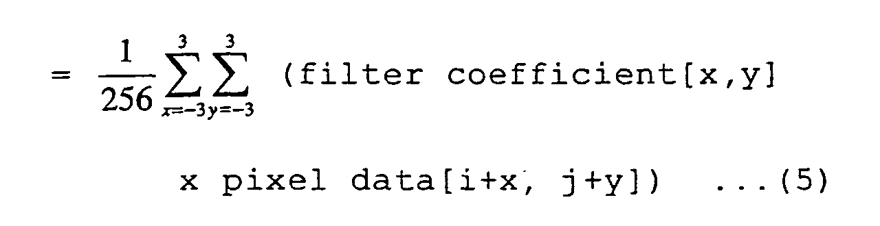
conversion function. The following formula (5)
represents a formula used for multi-level conversion.
output 256-level data[i,j]
In a case where the target image data are
binary data, a process using the spatial filter
represented by the above formula (5) is performed with
reference to pixels surrounding (within a two-dimensional
matrix) a 1-bit target pixel. When the
value of 1-bit data is 0, the 1-bit data are converted
to 8-bit data as 0×00, and when the value of 1-bit data
is 1, the 1-bit data are converted to 8-bit data as 0×FF
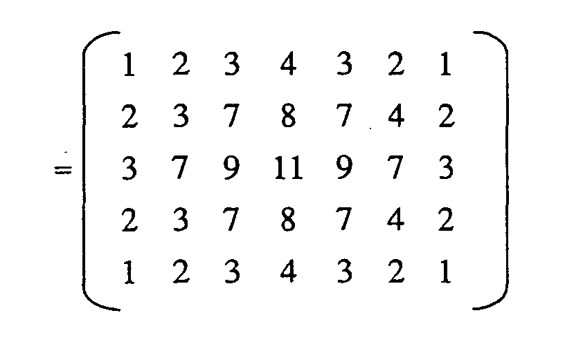
Then, a filter operation is performed based on the
filter (matrix) coefficients appended to the above
formula (5) and the formula (5). By performing the
filter operation, it is possible to convert the target
pixel data from binary to 256-level.
Additionally, in a case where data are smaller
than 8 bits, e.g., 2-bit, 3-bit or 4-bit, the data are
converted to 8 bits by using the spatial filter, which
performs smoothening. It should be noted that
conversion is not particularly performed when input data
are multi-level data.
A description is given below of a specific
case where image data are output to, for example, the
external PC 19. For example, it is assumed that the
following conditions are selected as the capture
conditions and supplied to the
printer controller 4.
| image kind mode | photograph |
| resolution | 200 dpi |
| halftone process | multi-level |
| output format | JPEG |
In this case, the image
format conversion unit 10 sets
processing conditions (parameters) in accordance with
the requirement and performs image processing.
In this example, after the image data (image
formation image) accumulated in the HDD 5 are converted
to multi-level by the multi-level conversion part 10g,
the following process is performed.
A resolution conversion parameter value used
for resolution conversion in the resolution conversion
part 10b is determined based on the requirement for the
resolution by the user and the resolution (here, 600
dpi) of the image data accumulated in the HDD 5. That
is, resolution conversion from 600 dpi to 200 dpi is
performed.
In the filtering part 10c and the γ process
part 10d, which follow the resolution conversion part
10b, coefficients corresponding to the requirement from
the external PC 19 are selected. In this example, since
the image kind mode requested by the user is the
photograph mode, the coefficient for the photograph mode
is selected in each of the filtering part 10c and the γ
process part 10d.
In addition, since "multi-level" is selected,
the halftone process part 10e does not perform a process.
In the compression part 10f, which follows the halftone
process part 10e, a conversion process to the JPEG file
format is performed.
In the aforementioned manner, it is possible
for the external PC 19 to receive (capture) from the
digital color copying machine 100 the image data (the
image formation data subjected to image processing for
copying such as color coordinate conversion from the RGB
system to the CMYK system, tone correction, and a
compression process) accumulated in the HDD 5 of the
digital color copying machine 100 in a state where the
image format is converted in accordance with the capture
conditions supplied from the external PC 19.
Here, the image data input in the first image
kind mode and accumulated in the storage device are
converted to image data of the second image kind mode in
accordance with the processing conditions, and
transmitted to the external instrument via the network.
Thus, it is possible for the external instrument to
receive from the image processing apparatus image data
whose image kind mode is converted to the desired image
kind mode. Hence, it is possible to use the image data
accumulated in the storage device for various purposes.
Additionally, since conversion of image kind mode is
performed on the image data that are already accumulated
in the storage device, it is possible for plural people
to receive the same image data in different image kind
modes.
Further, since it is possible to perform
conversion to the image kind mode in accordance with
processing conditions requested by the external
instrument irrespective of the image kind mode in a
copying operation, it is possible to satisfy
requirements related to the image kind mode by the
external instrument.
In each of the above embodiments, the external
PC 19 sets the capture conditions and receives
(captures) the image data from the digital color copying
machine 100. However, this is not a limitation. For
example, delivering conditions (processing conditions)
may be set by means of an operation part (operations
panel) P of the digital color copying machine 100 and
image data may be delivered to the predetermined
external PC 19.
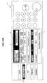
FIGS. 16A and 16B show examples of a display
screen image displayed on the operation part P of the
digital color copying machine 100 when a "document box
mode key" k for delivering image data from the digital
color copying machine 100 to the external PC 19 is
selected. An image data selection screen "e" as shown
in FIG. 16A is displayed on the operation part P, and it
is possible to view the image data accumulated in the
HDD 5 of the digital color copying machine 100. The
user of the digital color copying machine 100 selects
image data to be received in the image data selection
screen "e". In FIG. 16A, "DATA002" indicated by
hatching is selected. In addition, the user of the
digital color copying machine 100 also specifies a
delivering destination in a delivering destination
specification field "f" of the image data selection
screen "e". In FIG. 16A, the delivering destination is
specified by an e-mail address. However, the name of a
PC connected to the network may be specified instead.
When a delivering condition button "h" is operated in a
state where the image data to be delivered is selected
and the delivering destination is specified in the
aforementioned manner, a delivering condition selection
screen "i" shown in FIG. 16B is displayed on the
operation part P.
In the delivering condition selection screen
"i", it is possible to select conditions for capturing
image data such as the image kind mode, the resolution,
the halftone process, and the output format. In this
embodiment, as for the image kind mode, it is possible
to select each of the modes of "character", "character
and photograph", "photograph" and "OCR". As for the
resolution, it is possible to select 600 dpi, 400 dpi,
300 dpi or 200 dpi. As for the halftone process, it is
possible to select binary or multi-level. As for the
output format, is it possible to select TIFF, JPEG or
JPEG 2000. In the capture condition selection screen
"c" as mentioned above, the user operating the
external
PC 19 selects the conditions for capturing image data,
such as the image kind mode, the resolution, the
halftone process, and the output format. In FIG. 16B,
as indicated by hatching, the following conditions are
selected as the delivering conditions.
| image kind mode | character |
| resolution | 400 dpi |
| halftone process | binary |
| output format | TIFF |
When a deliver button "j" is operated in such a state
where the delivering conditions are selected as
mentioned above, the selected delivering conditions are
supplied to the
printer controller 4 of the digital
color copying machine 100.
The printer controller 4 that has received the
delivering conditions refers to the attributes of the
image data accumulated in the HDD 5, and issues an
instruction to the image format conversion unit 10 as to
what kind of image processing is to be performed.
Here, irrespective of the image kind mode at
the time of the copying operation, it is possible to
perform conversion to an image kind mode in accordance
with processing conditions requested by means of the
operation part P provided to the digital color copying
machine 100, and it is possible to specify by means of
the operation part P provided to the digital color
copying machine 100 an external instrument that is the
transmission destination of image data subjected to the
conversion to the image kind mode.
According to the present invention, the image
data input in the first image kind mode and accumulated
in the storage device are converted to the image data of
the second image kind mode in accordance with the
processing condition, and transmitted to the external
instrument connected to the image processing apparatus
via the network. Hence, it is possible for the external
instrument to receive from the image processing
apparatus the image data whose image kind mode is
converted to a desired image kind mode. Thus, it is
possible to use the image data accumulated in the
storage device for various purposes. In addition, since
conversion of image kind mode is performed on the image
data that are already accumulated in the storage device,
it is possible for plural people to receive the same
image data in different image kind modes.
Additionally, the present invention may be
applied to, for example, change of the image kind mode
with respect to monochrome image data.
Additionally, the present invention may be
applied to, for example, change of the image kind mode
with respect to color image data.
Additionally, irrespective of the image kind
mode at the time of a copying operation, it is possible
to perform conversion to an image kind mode in
accordance with the processing condition requested by
the external instrument, and it is possible to satisfy a
requirement related to the image kind mode required by
the external instrument.
Additionally, irrespective of the image kind
mode at the time of a copying operation, it is possible
to perform conversion to an image kind mode in
accordance with the processing condition requested by
means of the operation part provided to the image
processing apparatus, and it is possible to specify by
means of the operation part provided to the image
processing apparatus an external instrument that is the
transmission destination of the image data subjected to
the conversion to the image kind mode. Hence, it is
possible to satisfy a requirement related to the image
kind mode required with respect to the external
instrument.
Additionally, it is possible to positively
convert the image kind mode of image data from the first
image kind mode to the second image kind mode.
Additionally, according to the present
invention, since it is possible to convert image data to
image data having a desired resolution, it is possible
to satisfy the data contents required by the external
instrument.
Additionally, according to the present
invention, since it is possible to convert image data to
image data having a desired tone level, it is possible
to satisfy the data contents required by the external
instrument.
Additionally, according to the present
invention, since it is possible to convert image data to
image data of a desired file format, it is possible to
satisfy the data contents required by the external
instrument.
The present invention is not limited to the
specifically disclosed embodiments, and variations and
modifications may be made without departing from the
scope of the present invention.