BACKGROUND OF THE INVENTION
FIELD OF THE INVENTION
-
The present invention relates to a master carrier for
magnetic transfer, which has a magnetic layer with a transfer
pattern formed therein for transferring information data to a
magnetic recording medium.
DESCRIPTION OF THE RELATED ART
-
Increasing the recording density of magnetic recording
media is now in great progress so as to satisfy the requirement
for the increase in information contents of today. In a magnetic
recording medium having a high recording density, the
information-recording region has a narrow track. In order to
precisely trace a magnetic head along such a narrow track to
thereby reproduce signals at a high S/N ratio, a tracking servo
technique for magnetic heads is an important theme.
-
In order that a magnetic head could trace along the
recording track of a magnetic recording medium, the recording
medium must be preformatted with the necessary servo information
that includes positioning servo signals, tracking address
signals and regeneration clock signals, while it is produced.
-
For preformatting magnetic recording media, a dedicated
servo-write device (servotrackwriter) isusedatpresent. With
it, however, a magnetic head must be scanned on every magnetic
recording medium for preformatting it one by one, and it takes
a long period of time. Therefore, for increasing the
productivity in preformatting, a large number of servo-write
devices must be driven all at a time. However, introduction
and maintenance of such a large number of servo-write devices
is expensive.
-
It is anticipated that increasing the recording density
of magnetic recording media will be in greater progress in future
and the track density thereof will therefore further increase.
-
In that situation, a study of magnetic transfer is now
in progress, which comprises keeping the surface of a magnetic
recording medium that has a magnetic recording region in its
surface, in intimate contact with the surface of a master carrier
that has a transfer pattern of servo signals and others formed
of a magnetic material on the surface of a support thereof, and
applying a transfer magnetic field to the master carrier in that
condition to thereby magnetically transfer the transfer pattern
of the master carrier to the magnetic recoding medium all at
a time.
-
When the magnetic recording media referred to hereinabove
are disc-shaped ones such as hard discs or high-density flexible
discs, then a disc-shaped master carrier is kept in intimate
contact with one or both faces of the magnetic recording medium
of the type and, in that condition, a transfer magnetic field
is applied to one or both surfaces thereof by the use of a magnetic
field applicator with electromagnets or permanent magnets (for
example, see U.S.Patent No. 6,347,016).
-
For correctly transferring and recording a transfer
pattern of a master carrier to a magnetic recording medium (slave
medium) in a mode of magnetic transfer, it is important to apply
a magnetic field to the magnetic recording medium while it is
in uniform and intimate contact with the master carrier.
-
Fig. 8 is an explanatory view schematically showing a
conventional master carrier 100 and a magnetic recording medium
200 that are put on top of each other. As in Fig. 8, when there
exists a space S between the master carrier 100 and the magnetic
recording medium 200, then the fine uneven transfer pattern (not
shown) provided in the transfer region of the master carrier
100 could not be in uniform and intimate contact with the magnetic
recording region formed in the surface of the magnetic recording
medium 200 and therefore the transfer pattern could not be
correctly transferred to the magnetic recording region.
-
The cause of the space S wouldbe that the warp or distortion
occurred in the master carrier 100 may be high-ordered when kept
in intimate contact, and the support 101 of the master carrier
100 is thereby deformed, and the face of the support 101 is curved.
-
Fig. 9 is a plan view of the master carrier 100 of Fig.
8, seen on its top. Fig. 10 is a graphical view showing the
warp of the master carrier 100 of Fig. 9, in the radial direction
thereof (in the direction of the arrow R in the drawing). Fig.
11 is a graphical view showing the distortion of themaster carrier
100 of Fig. 9, in the peripheral direction thereof (in the
direction of the arrow C in the drawing).
-
"Warp" as referred to herein means the displacement of
the support surface in the radial direction of the master carrier,
as in Fig. 9 and Fig. 10. "Distortion" also referred to herein
means the displacement of the support surface in the
circumferential direction of the master carrier, as in Fig. 9
and Fig. 11.
-
Heretofore, a magnetic field is applied to a magnetic
recording medium and a master carrier that are in uniform and
intimate contact with each other while an external load is applied
thereto so as not to form a clearance gap between the two. However,
since the master carrier is warped or distorted by itself, it
is extremely difficult to ensure uniform and intimate contact
between the mater carrier and the magnetic recording medium
attached thereto.
-
On the other hand, it was impossible to completely remove
warp and distortion from master carriers in view of the process
of producing them.
-
For these reasons, there occurs a space between the
magnetic recording medium and the master carrier that are kept
in contact with each other, owing to the high-ordered warp and
distortion of the master carrier, and, as a result, the transfer
efficiency is lowered and magnetic recording media could not
be correctly preformatted. In this point, there is still room
for improvement in the transfer technique.
SUMMARY OF THE INVENTION
-
The present invention has been made in consideration of
the above-mentioned situation, and its object is to provide a
master carrier for magnetic transfer, which can be in intimate
and improved contact with a magnetic recording medium attached
thereto to attain good transfer efficiency.
-
The above-mentioned object of the invention can be
attained by a master carrier for magnetic transfer which
comprises a support having an uneven transfer pattern that
corresponds to the information to be transferred to a magnetic
recording medium and a magnetic layer formed on the surface of
the support, wherein a relief is formed in the site where the
transfer pattern is not formed. The term "relief" as used herein
means that a portion where the uneven transfer pattern is not
formed, and it is formed by thinning a thickness of the master
carrier in a perpendicular direction of the master carrier at
opposite sides of the surface having the uneven transfer pattern.
-
The master carrier for magnetic transfer (hereinafter
this is simply referred to as "master carrier") of the invention
is so designed that its support in the site where the relief
is formed is thinner than in the other site where no relief is
formed. Therefore the master carrier is not so rigid and can
be readily deformed owing to the defection of the support.
-
Accordingly, even when the support of the master carrier
has warp and distortion, the deflection thereof caused by the
warping or distortion may concentrate in the relief and, as a
result, the support may be deformed only in the site where the
relief is formed. In other words, even if the support of the
master carrier is warped or distorted while the master carrier
is kept in intimate contact with a magnetic recording medium
attached thereto, the deflection of the support caused by the
warping or distortion thereof may concentrate in the relief or,
that is, the warp and the distortion may be thereby allowed.
Accordingly, the transfer pattern-having site of the master
carrier that is in direct contact with a magnetic recording medium
is prevented from being deflected and, as a result, the master
carrier may be kept in uniform and intimate contact with the
magnetic recording medium attached thereto.
-
Accordingly, the master carrier for magnetic transfer
of the invention ensures good and intimate contact with a magnetic
recording medium attached thereto, and therefore ensures good
transfer efficiency. The master carrier of the present
invention and the method using the same are specifically
described below.
- (1). A master carrier for magnetic transfer, including:
a support having an uneven transfer pattern on a surface of the
support, the uneven transfer pattern corresponding to
information to be transferred to a magnetic recording medium;
and a magnetic layer on the surface of the support,
wherein the master carrier has a relief in a site where
the uneven transfer pattern is not formed, the relief being formed
by thinning a thickness of the master carrier in a perpendicular
direction of the master carrier at opposite sides of the surface
having the uneven transfer pattern. - (2) . The master carrier for magnetic transfer of item
1, wherein the relief extends from inside to outside in a radial
direction of the master carrier.
- (3) . The master carrier for magnetic transfer of item1,
wherein the relief spreads with extending to outside in a radial
direction.
- (4). The master carrier for magnetic transfer of item
1, wherein a thickness of the master carrier in the relief
gradually decreases with extending to outside in a radial
direction.
- (5). The master carrier for magnetic transfer of item
1, wherein a thickness of the master carrier in the relief
gradually increases with extending to outside in a radial
direction.
- (6). A master carrier formagnetic transfer, including:
a support having an uneven transfer pattern on a surface of the
support, the uneven transfer pattern corresponding to
information to be transferred to a magnetic recording medium;
and a magnetic layer on the surface of the support,
wherein the master carrier has a through-hole in a site
where the uneven transfer pattern is not formed, the through-hole
running through in a perpendicular direction of the master
carrier. - (7). The master carrier for magnetic transfer of item
(6), wherein the through-hole extends from inside to outside
in a radial direction of the master carrier.
- (8). A master carrier formagnetic transfer, including:
a support having an uneven transfer pattern on a surface of the
support, the uneven transfer pattern corresponding to
information to be transferred to a magnetic recording medium;
and a magnetic layer on the surface of the support,
wherein the master carrier has a slit in a site where
the uneven transfer pattern is not formed, and the slit runs
through in a direction of a perpendicular direction of the master
carrier and extends from inside to outside in a radial direction
of the master carrier, the slit being so formed that it breaks
one of an outer periphery and an inner periphery of the support
in a peripheral direction of the master carrier. - (9). A process of producing a preformatted magnetic
recording medium, which comprises the steps of:
- preparing a master carrier,
- preparing a slave medium including a non-magnetic support
having a magnetic recording layer thereon,
- initially magnetizing the magnetic recording layer of
the slave medium to a predetermined direction,
- bringing a surface of the master carrier into intimate
contact with the magnetic recording layer of the slave medium
at a predetermined pressure to form a conjoined body, and
- applying a transfer magnetic field to the conjoined body
in a direction opposite to the predetermined direction, thereby
obtaining themagnetic recording medium having the recordeddata,
wherein the master carrier, which comprises a support
having an uneven transfer pattern on a surface of the support,
the uneven transfer pattern corresponding to information to be
transferred to the slave medium; and a magnetic layer on the
surface of the support, has a relief in a site where the uneven
transfer pattern is not formed, the relief being formed by
thinning a thickness of the master carrier in a perpendicular
direction of the master carrier at opposite sides of the surface
having the uneven transfer pattern. - (10). The process of producing a preformatted magnetic
recording medium of item (9), wherein the relief extends from
inside to outside in a radial direction of the master carrier.
- (11). The process of producing a preformatted magnetic
recording medium of item (9), wherein the relief spreads with
extending to outside in a radial direction.
- (12). The master carrier for magnetic transfer of item
(9), wherein a thickness of the master carrier in the relief
gradually decreases with extending to outside in a radial
direction.
- (13). The master carrier for magnetic transfer of item
(9), wherein a thickness of the master carrier in the relief
gradually increases with extending to outside in a radial
direction.
-
-
The master carrier for magnetic transfer of the invention
can be in intimate and improved contact with a magnetic recording
medium attached thereto and attains good transfer efficiency.
BRIEF DESCRIPTION OF THE DRAWINGS
-
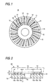
- FIG. 1 is an explanatory plan view schematically showing a first
embodiment of the master carrier for magnetic transfer of the
invention.
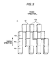
- FIG. 2 is an explanatory cross-sectional view schematically
showing the cross section of the master carrier for magnetic
transfer of Fig. 1, cut along the line A-A.
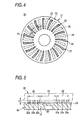
- FIG. 3 is an explanatory view graphically showing the transfer
pattern of the transfer region of the master carrier.
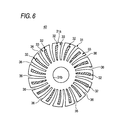
- FIG. 4 is an explanatory plan view schematically showing a second
embodiment of the master carrier for magnetic transfer of the
invention.
- FIG. 5 is an explanatory cross-sectional view schematically
showing the cross section of the master carrier for magnetic
transfer of Fig. 4, cut along the line B-B.
- FIG. 6 is an explanatory plan view schematically showing a third
embodiment of the master carrier for magnetic transfer of the
invention.
- FIG. 7 is an explanatory plan view schematically showing a fourth
embodiment of the master carrier for magnetic transfer of the
invention.
- FIG. 8 is an explanatory view schematically showing a
conventional master carrier and a magnetic recording medium that
are put on top of each other.
- FIG. 9 is a plan view of the master carrier of Fig. 8, seen on
its top.
- FIG. 10 is a graphical view showing the warp of a conventional
master carrier in the radial direction thereof.
- FIG. 11 is a graphical view showing the distortion of a
conventional master carrier in the peripheral direction thereof.
-
DETAILED DESCRIPTION OF THE INVENTION
-
Embodiments of the invention are described in detail
hereinunder with reference to the drawings attached hereto.
-
FIG. 1 is an explanatory plan view schematically showing
a first embodiment of the master carrier for magnetic transfer
of the invention. FIG. 2 is an explanatory cross-sectional view
schematically showing the cross section of the master carrier
for magnetic transfer of FIG. 1, cut along the line A-A. FIG.
3 is an explanatory view graphically showing the transferpattern
of the transfer region of the master carrier.
-
As in Fig. 1 to Fig. 3, the master carrier 10 is formed
like a disc, and its surface has a plurality of transfer regions
12 each having a transfer pattern of fine protruded portions
12a formed to correspond to the information signals to be
transferred to a magnetic recording medium 20 shown by the broken
line in FIG. 2, and a non-transfer region 13 where these protruded
portions 12a are not formed. In FIG. 1, the transfer regions
12 are hatched.
-
In the center of the support 11, a circular opening is
formed to run through in the direction of the thickness of the
support 11, and this is for registration in transfer to the
magnetic recording medium 20.
-
Plural transfer regions 12 all extend in strips fromaround
the center of the master carrier 10 toward the peripheral edge
thereof in the radial direction, and they are formed in the surface
of the master carrier 10 at a predetermined angle relative to
the peripheral direction thereof.
-
As in FIG. 2, when the magnetic recording medium 20 is
disposed adjacent to the surface of the master carrier 10 for
magnetic transfer to it, then the upper faces of theprotruded
portion 12a are kept in intimate contact with the recording region
of the magnetic recording medium 20.
-
The information signals tobe transferred are, for example,
tracking servo signals, clock signals and address information
signals, but are not limited to these. The pattern of fine
protruded portion 12a is suitably designed in point of its
disposition, in accordance with the information to be transferred
to the magnetic recording medium.
-
As in FIG. 2, the master carrier 10 comprises the disc-like
support 11 formed of a magnetic material, and a magnetic layer
14 formed on the surface of the support 11. In this embodiment,
the magnetic layer 14 is formed on the entire surface of the
support 11. Not limited to this, however, the magnetic layer
14 may be formed at least on the protruded portion 12a in the
transfer region 12.
-
Preferably, the fine protruded portion 12a is so designed
that its height, h, from the surface of the support 11 in the
site where the protruded portion 12a are not formed is from 5
nm to 1 µm. More preferably, the height, h, is from 20 nm to
300 nm.
-
The magnetic material of the support 11 and that of the
magnetic layer 14 are so selected that the saturation
magnetization, Ms, of the support 11 and the saturation
magnetization, Mm, of the magnetic layer 14 may satisfy the
relation of 1.0 < Mm/Ms < 100, preferably 2.0 ≤ Mm/Ms < 3.9.
The saturation magnetization, Ms, of the support 11 is at least
5.65 T (4500 Gauss). Concretely, the support 11 may be formed
of Ni or an Ni alloy. The magnetic layer 14 may be formed of
an alloy material such as FeCo, FeCoNi, FeNi or the like that
has a face-centered cubic structure and contains at least one
element selected from Fe, Co, Ni, Gd, Dy, Sm and Nd. Any other
material that contains anyothermagnetic element or non-magnetic
element may also be used herein so far as it is ferromagnetic
as a whole. The magnetic layer may be a soft magnetic, semi-hard
magnetic or hard magnetic one. Preferably, however, it is a
soft magnetic or semi-hardmagnetic layer having a small coercive
force, as enabling better magnetic transfer.
-
Also preferably, the magnetic layer 14 to be formed on
the support 11 has a body-centered cubic structure (bcc), a
face-centered cubic structure (fcc), or an amorphous structure.
When the magnetic layer 14 has a bcc structure or a fcc structure,
then it is desirable that the layer has a packing structure of
a number of irregularly-disposed fine particles and eachparticle
therein has a size of at most 100 nm measured from the face of
the layer.
-
The magnetic layer 14 may be formed by applying a magnetic
material to the support in a mode of vacuum film formation such
as vacuum deposition, sputtering or ion-plating, or though
plating. Preferably, the thickness of the magnetic layer 14
is from 25 nm to 500 nm, more preferably from 80 nm to 300 nm.
-
Preferably, a protective film of diamond-like carbon
(DLC) or sputtered carbon having a thickness of from 2 nm to
30 nm is formed on the surface of the magnetic layer. If desired,
a lubricant layer may be formed thereon. Between the magnetic
layer 14 and the protective film, an adhesiveness-enhancing layer
of Si or the like maybe provided. While in contact with a magnetic
recording medium, the master carrier may be incorrectly
positioned, and when it is corrected, it may receive friction.
The lubricant layer will be effective for preventing the master
carrier from being scratched owing to the friction, and will
be effective for improving the durability of the master carrier.
-
One example of the process of forming the support 11 in
this embodiment is described.
-
First, an adhesiveness-enhancing liquid is applied to
an Si support (for undercoating the support), and a resist liquid
is applied thereto and baked. Next, the Si support is exposed
for patterning (EBR), and then baked, and thereafter developed
and further baked. Next, an Ni-conductive film is formed on
it by sputtering for Ni-electroforming, and then this is peeled
to give a base (base 1).
-
A replica of the base 1 is formed, and this is referred
to as a base 2. Briefly, the base 1 is oxidized, then an Ni
film is formed on it in a mode of Ni-electroforming, and then
peeled, and the resist is removed to give the base 2. Further,
a base 3 is formed from the base 2, and the same master base
as the above base 1 is thus obtained.
-
Next, a protective film is formed on the pattern surface
of each base, and optionally polished, and the polish powder
formed in the polishing step is removed. Next, a protective
film is also formed on the back of each base. Thus processed,
the base is blanked into a piece having a desired size, and this
is a master support. A magnetic layer mentioned above is formed
on the master support.
-
In this embodiment, the master support is processed into
a doughnut-like disc (center-holeddisc), asinFIG. 1. Briefly,
it is processed by blanking with a blanking machine equipped
with an upper blade and a lower blade that engage with each other,
or by photoetching, laser cutting, water cutting or lathing.
-
In the master carrier 10 of this embodiment, a plurality
of through-holes 16 are formed in the non-transfer region 13
thereof not having the protruded portion 12a, and they all run
through in the direction of the thickness of the support 11.
These through-holes 16 each function as a relief.
-
As in FIG. 1, these through-holes 16 are formed in the
non-transfer region 13, and, sandwiched between the adjacent
transfer regions 12, each through-hole 16 extends almost radially
from the center of the support 11 toward the outer peripheral
edge thereof.
-
In the support 11, the site where the through-holes 16
are formed is thinner than any other site where the through-holes
16 are not formed, and therefore, the support 11 is not so rigid
and may be readily deformed when it is deflected.
-
In this embodiment, even when the support 11 of the master
carrier 10 is warped or distorted, the deflection thereof caused
by the warping or distortion may concentrate around the
through-holes 16 and the inner peripheral face of each
through-holes 16 may suitably expand and contract, and, as a
result, the support 11 may be deformed only in the site where
the through-holes 16 are formed. In other words, even if the
support 11 is warped or distorted while the master carrier 10
is kept in intimate contact with the magnetic recording medium
20 attached thereto, the deflection of the support 11 caused
by the warping or distortion thereof may concentrate around the
through-holes 16, and therefore the warp and the distortion may
be thereby allowed. Accordingly, the transfer pattern-having
site of the master carrier 10 that is in direct contact with
the magnetic recording medium 20 is prevented from being
deflected and, as a result, the master carrier 10 may be kept
in uniform and intimate contact with the magnetic recording
medium 20.
-
With respect to their shape, the through-holes 16 are
not limited to those of this embodiment and may have any other
shape so far as they may absorb the deformation caused by the
deflection resulting from the warping or distortion of the
support of the master carrier. For example, a plurality of
through-holes that are circular in the plan view of the support
may be formed at predetermined intervals in the non-transfer
region 13.
-
Next described is a second embodiment of the invention.
FIG. 4 is an explanatory plan view schematically showing a second
embodiment of the master carrier for magnetic transfer of the
invention. FIG. 5 is an explanatory cross-sectional view
schematically showing the cross section of the master carrier
for magnetic transfer of FIG. 4, cut along the line B-B. In
the embodiments described hereinunder, the members that are the
same as those already mentioned hereinabove in point of their
constitution and function are designated by the same or
corresponding numeral references, and their description is
simplified or omitted.
-
As in FIGs. 4 and 5, the master carrier 30 of this embodiment
is so designed that the support 21 thereof has recesses 26 formed
in the face thereof opposite to the other face covered with a
magnetic layer 24, or that is, the support 21 is thinned at the
recesses 26. The recesses 26 each function as a relief.
-
In this embodiment, the site of the support 21 where the
recesses 26 are formed is not so rigid as compared with the other
site thereof where the recesses 26 are not formed. Accordingly,
in this, even when the support 21 is warped or distorted, the
deflection thereof caused by the warping or distortion may
concentrate in and around the recesses 26 and the inner peripheral
face and the bottom of each recess 26 may suitably expand and
contract, and, as a result, the support 21 may be deformed only
in the site where the recesses 26 are formed. Therefore, the
master carrier 30 may be kept in uniform and intimate contact
with the magnetic recording medium 20 attached thereto.
-
Next described is a third embodiment of the invention.
FIG. 6 is an explanatory plan view schematically showing a third
embodiment of the master carrier for magnetic transfer of the
invention.
-
As in FIG. 6, the master carrier 40 of this embodiment
is so designed that the support 31 thereof has slits 36 each
running through in the direction of the thickness of the support
31 and extending radially from the outer peripheral edge 31a
of the support 31 toward the inner peripheral edge 31b thereof.
The slits 36 each function as a relief.
-
In this embodiment, the site of the support 31 where the
slits 36 are formed is not so rigid as compared with the other
site thereof where the slits 36 are not formed. In addition,
since the outer peripheral edge 31a of the support 31 is cut
by the slits 36 at predetermined intervals in the peripheral
direction thereof, the warp or distortion that may occur in the
support 31 may be more efficiently relieved, and therefore the
deformation to be caused by the warp or distortion is prevented
from propagating to the transfer region 32. Accordingly, the
master carrier 40 may be kept in uniform and intimate contact
with the magnetic recording medium 20 attached thereto (see FIG.
2) .
-
In this embodiment, the support 31 may be processed to
have the slits 36 in such a condition that the non-transfer region
33 of the support 31 is removed to form the slits 36 while the
inner peripheral edges 31b is left as such, within a range within
which the thus-slit support 31 can still ensure the minimum
necessary mechanical strength thereof.
-
Next described is a fourth embodiment of the invention.
FIG. 7 is an explanatory plan view schematically showing a fourth
embodiment of the master carrier for magnetic transfer of the
invention.
-
As in FIG. 7, the master carrier 50 of this embodiment
is so designed that the support 41 thereof has slits 36 each
running through in the direction of the thickness of the support
41 and extending radially from the inner peripheral edge 41b
of the support 41 toward the outer peripheral edge 41a thereof.
The slits 46 each function as a relief.
-
In this embodiment, the site of the support 41 where the
slits 46 are formed is not so rigid as compared with the other
site thereof where the slits 46 are not formed, like in the third
embodiment mentioned above. In addition, since the inner
peripheral edge 41b of the support 41 is cut by the slits 46
at predetermined intervals in the peripheral direction thereof,
the warp or distortion that may occur in the support 41 may be
more efficiently relieved, and therefore the deformation to be
caused by the warp or distortion is prevented from propagating
to the transfer region 42. Accordingly, the master carrier 50
may be kept in uniform and intimate contact with the magnetic
recording medium 20 attached thereto (see FIG. 2).
-
In this embodiment, the support 41 may be processed to
have the slits 46 in such a condition that the non-transfer region
43 of the support 41 is removed to form the slits 46 while the
outer peripheral edges 41a is left as such, within a range where
the thus-slit support 41 can still ensure the minimum necessary
mechanical strength thereof.
-
In the third and fourth embodiments, the slits 36, 46
are formed to cut the outer peripheral edge 31a or the inner
peripheral edge 41b of the support 31 or 41 at predetermined
intervals in the peripheral direction of the support. Not
limited to these, some but not all of the slits 36, 46 may run
through the outer peripheral edge 31a or the inner peripheral
edge 41b in the radial direction of the support while the others
do not. However, it is desirable that all the slits 36, 46 run
through the outer peripheral edge 31a or the inner peripheral
edge 41b in the radial direction of the support, as in the third
and fourth embodiments illustrated herein. This is because,
when the master carrier 40 or 50 of the preferred embodiments
is kept in intimate contact with the magnetic recording medium
20 (see FIG. 2), then air may pass through the slits 36, 46 not
staying between the two, and the intimate contact of the two
may be ensured.
-
The invention shouldnot be limited to the above-mentioned
embodiments, and may be modified and improved in any desired
manner.
-
For example, the relief is not limited to those in the
above-mentioned embodiments, and may have any desired shape so
far as it is effective for lowering the rigidity of the site
around it than in any other site of the support.
-
In the above-mentioned embodiments, for example, the
relieves are all formed radially in the in-plane direction of
the support. Not limited to these, they may be formed in the
peripheral direction of the support so far as they do not interfere
with the transfer region of the master carrier. However, the
radial relieves may absorb the warp and distortion of the support
more efficiently, therefore preventing the support from
deforming, and they are more effective for further improving
the intimate contact of the master carrier to the magnetic
recording medium attached thereto.
-
For example, in the above-mentioned embodiments, the
relieves are formed in the surface of the support opposite to
the surface thereof coated with a magnetic layer. Not limited
to these, recesses may be formed in the same surface of the support
coated a magnetic layer in such a manner that they do not interfere
with the site of the master carrier where the transfer pattern
is formed.
-
The present invention claims foreign priority based on
Japanese Patent application no. 2003-280404, filed on July 25,
2003, the contents of which is incorporated herein by reference.