EP1500989A1 - Electrophotographic image recording apparatus and method therefore using light and dark toner of the same hue - Google Patents
Electrophotographic image recording apparatus and method therefore using light and dark toner of the same hue Download PDFInfo
- Publication number
- EP1500989A1 EP1500989A1 EP04016103A EP04016103A EP1500989A1 EP 1500989 A1 EP1500989 A1 EP 1500989A1 EP 04016103 A EP04016103 A EP 04016103A EP 04016103 A EP04016103 A EP 04016103A EP 1500989 A1 EP1500989 A1 EP 1500989A1
- Authority
- EP
- European Patent Office
- Prior art keywords
- image
- toner
- hypochromic
- hyperchromic
- forming
- Prior art date
- Legal status (The legal status is an assumption and is not a legal conclusion. Google has not performed a legal analysis and makes no representation as to the accuracy of the status listed.)
- Granted
Links
- 238000000034 method Methods 0.000 title claims description 27
- 230000000215 hyperchromic effect Effects 0.000 claims abstract description 37
- 238000012546 transfer Methods 0.000 claims description 54
- 239000000463 material Substances 0.000 claims description 20
- 238000011161 development Methods 0.000 claims description 17
- 230000008569 process Effects 0.000 claims description 14
- 230000000694 effects Effects 0.000 claims description 7
- 230000015572 biosynthetic process Effects 0.000 abstract description 12
- 239000000976 ink Substances 0.000 description 12
- 239000002245 particle Substances 0.000 description 10
- 239000003086 colorant Substances 0.000 description 8
- 239000007787 solid Substances 0.000 description 6
- 230000006872 improvement Effects 0.000 description 5
- 239000011159 matrix material Substances 0.000 description 5
- 238000006243 chemical reaction Methods 0.000 description 4
- 238000012937 correction Methods 0.000 description 4
- 230000003287 optical effect Effects 0.000 description 4
- 230000001105 regulatory effect Effects 0.000 description 4
- 238000003705 background correction Methods 0.000 description 3
- 238000005516 engineering process Methods 0.000 description 3
- 239000011521 glass Substances 0.000 description 3
- 230000000873 masking effect Effects 0.000 description 3
- 238000012545 processing Methods 0.000 description 3
- 230000004075 alteration Effects 0.000 description 2
- 238000004140 cleaning Methods 0.000 description 2
- 238000010586 diagram Methods 0.000 description 2
- 230000005684 electric field Effects 0.000 description 2
- 230000001788 irregular Effects 0.000 description 2
- 238000005259 measurement Methods 0.000 description 2
- 239000000203 mixture Substances 0.000 description 2
- 238000005192 partition Methods 0.000 description 2
- 238000001454 recorded image Methods 0.000 description 2
- 238000009877 rendering Methods 0.000 description 2
- 230000004044 response Effects 0.000 description 2
- 229920002379 silicone rubber Polymers 0.000 description 2
- 239000004945 silicone rubber Substances 0.000 description 2
- XAGFODPZIPBFFR-UHFFFAOYSA-N aluminium Chemical compound [Al] XAGFODPZIPBFFR-UHFFFAOYSA-N 0.000 description 1
- 229910052782 aluminium Inorganic materials 0.000 description 1
- 230000003321 amplification Effects 0.000 description 1
- 230000005540 biological transmission Effects 0.000 description 1
- 230000008859 change Effects 0.000 description 1
- 230000001934 delay Effects 0.000 description 1
- 230000003111 delayed effect Effects 0.000 description 1
- 230000006866 deterioration Effects 0.000 description 1
- 230000008030 elimination Effects 0.000 description 1
- 238000003379 elimination reaction Methods 0.000 description 1
- 239000000284 extract Substances 0.000 description 1
- 230000004907 flux Effects 0.000 description 1
- 230000006870 function Effects 0.000 description 1
- 238000009499 grossing Methods 0.000 description 1
- 239000000696 magnetic material Substances 0.000 description 1
- 239000006249 magnetic particle Substances 0.000 description 1
- 238000012986 modification Methods 0.000 description 1
- 230000004048 modification Effects 0.000 description 1
- 238000003199 nucleic acid amplification method Methods 0.000 description 1
- 230000002093 peripheral effect Effects 0.000 description 1
- 230000000704 physical effect Effects 0.000 description 1
- -1 polyethylene terephthalate Polymers 0.000 description 1
- 229920000139 polyethylene terephthalate Polymers 0.000 description 1
- 239000005020 polyethylene terephthalate Substances 0.000 description 1
- 239000011347 resin Substances 0.000 description 1
- 229920005989 resin Polymers 0.000 description 1
- 239000004065 semiconductor Substances 0.000 description 1
- 230000035945 sensitivity Effects 0.000 description 1
- 230000003595 spectral effect Effects 0.000 description 1
- 230000000087 stabilizing effect Effects 0.000 description 1
- 229910001220 stainless steel Inorganic materials 0.000 description 1
- 239000010935 stainless steel Substances 0.000 description 1
- 230000003746 surface roughness Effects 0.000 description 1
- 230000001360 synchronised effect Effects 0.000 description 1
- 238000012360 testing method Methods 0.000 description 1
- 230000001131 transforming effect Effects 0.000 description 1
Images



Classifications
-
- G—PHYSICS
- G03—PHOTOGRAPHY; CINEMATOGRAPHY; ANALOGOUS TECHNIQUES USING WAVES OTHER THAN OPTICAL WAVES; ELECTROGRAPHY; HOLOGRAPHY
- G03G—ELECTROGRAPHY; ELECTROPHOTOGRAPHY; MAGNETOGRAPHY
- G03G15/00—Apparatus for electrographic processes using a charge pattern
- G03G15/01—Apparatus for electrographic processes using a charge pattern for producing multicoloured copies
- G03G15/0105—Details of unit
- G03G15/0121—Details of unit for developing
-
- G—PHYSICS
- G03—PHOTOGRAPHY; CINEMATOGRAPHY; ANALOGOUS TECHNIQUES USING WAVES OTHER THAN OPTICAL WAVES; ELECTROGRAPHY; HOLOGRAPHY
- G03G—ELECTROGRAPHY; ELECTROPHOTOGRAPHY; MAGNETOGRAPHY
- G03G15/00—Apparatus for electrographic processes using a charge pattern
- G03G15/01—Apparatus for electrographic processes using a charge pattern for producing multicoloured copies
- G03G15/0105—Details of unit
- G03G15/011—Details of unit for exposing
- G03G15/0115—Details of unit for exposing and forming a half-tone image
-
- H—ELECTRICITY
- H04—ELECTRIC COMMUNICATION TECHNIQUE
- H04N—PICTORIAL COMMUNICATION, e.g. TELEVISION
- H04N1/00—Scanning, transmission or reproduction of documents or the like, e.g. facsimile transmission; Details thereof
- H04N1/40—Picture signal circuits
- H04N1/40087—Multi-toning, i.e. converting a continuous-tone signal for reproduction with more than two discrete brightnesses or optical densities, e.g. dots of grey and black inks on white paper
-
- G—PHYSICS
- G03—PHOTOGRAPHY; CINEMATOGRAPHY; ANALOGOUS TECHNIQUES USING WAVES OTHER THAN OPTICAL WAVES; ELECTROGRAPHY; HOLOGRAPHY
- G03G—ELECTROGRAPHY; ELECTROPHOTOGRAPHY; MAGNETOGRAPHY
- G03G2215/00—Apparatus for electrophotographic processes
- G03G2215/01—Apparatus for electrophotographic processes for producing multicoloured copies
- G03G2215/0167—Apparatus for electrophotographic processes for producing multicoloured copies single electrographic recording member
- G03G2215/0174—Apparatus for electrophotographic processes for producing multicoloured copies single electrographic recording member plural rotations of recording member to produce multicoloured copy
- G03G2215/0177—Rotating set of developing units
-
- G—PHYSICS
- G03—PHOTOGRAPHY; CINEMATOGRAPHY; ANALOGOUS TECHNIQUES USING WAVES OTHER THAN OPTICAL WAVES; ELECTROGRAPHY; HOLOGRAPHY
- G03G—ELECTROGRAPHY; ELECTROPHOTOGRAPHY; MAGNETOGRAPHY
- G03G2215/00—Apparatus for electrophotographic processes
- G03G2215/06—Developing structures, details
- G03G2215/0602—Developer
- G03G2215/0604—Developer solid type
- G03G2215/0624—Developer solid type plural systems represented (e.g. in a multicolour device or for optimising photo line development)
Definitions
- the present invention relates to an image forming apparatus for color image formation by an electrophotographic method, such as a copying apparatus, a printer or a facsimile apparatus, and a method for use therein.
- an image forming apparatus for forming a color image there is commercialized an apparatus capable of forming a color image for example by transferring, on a transfer material such as paper supported on a transfer drum (or transfer film), in succession toner images of respective colors formed on a photosensitive drum serving as an image bearing member.
- an electrostatic latent image formed on the photosensitive drum in response to an input image signal is developed with toner of a first color (for example cyan color) to form a toner image, which is transferred onto a transfer material such as paper supported on a transfer drum (transfer film).
- This transfer step is executed similarly for the toners of three other colors, namely magenta, yellow and black, and a color image can be obtained by superposed transfers of the toner images of four colors in succession on the transfer material.
- the latent image is formed by an assembly of dots of a predetermined potential on the surface of a latent image bearing member, or so-called photosensitive member, and a solid image area, a halftone area and a line image area are represented by a change in the density of the dots.
- a latent image bearing member or so-called photosensitive member
- a solid image area, a halftone area and a line image area are represented by a change in the density of the dots.
- the latent image formed by such small dots becomes more difficult to reproduce, thus often resulting in an image with insufficient sharpness, poor in resolution and in gradation particularly in a highlight area.
- an irregular deviation of the dots gives an impression of granularity, thus constituting a factor leading to a deterioration of the image quality in the highlight area.
- Such noise is made more conspicuous by a difference between the toner density and the density of the paper.
- a main cause of the aforementioned phenomena lies in a fact that the electrophotography utilizes small toner particles for forming a dot.
- hypochromic toner is far more effective in the electrophotography than in the ink jet process, particularly on the apparent low-frequency noise resulting from the aforementioned phenomena of "fluctuation in the toner density forming the dot", "fluctuation in the dot area” and “fluctuation in the dot shape” in the electrophography.
- the introduction of the hypochromic toner into the electrophotography brings about a revolutionary improvement based on a fact that the optical dot gain which is not a problem in the ink jet system constitutes a significant obstacle in attaining a high image quality in the electrophotography utilizing numberless small toner particles.
- Japanese Patent Application Laid-Open Nos. H11-84764 and 2000-305339 propose image forming method by combining plural toners of respectively different densities.
- Japanese Patent Application Laid-Open No. 2000-347476 proposes an image forming apparatus utilizing a combination of a hyperchromic toner and a hypochromic toner, having a maximum reflective density equal to or less than a half of the maximum reflective density of the hyperchromic toner.
- 2000-231279 proposes an image forming apparatus utilizing a combination of a hyperchromic toner, having an image density of 1.0 or higher at a toner amount of 0.5 mg/cm 2 on the transfer material, and a hypochromic toner having an image density less than 1.0.
- Japanese Patent Application Laid-Open No. 2001-290319 proposes an image forming apparatus utilizing a combination of a hyperchromic toner and a hypochromic toner, having an inclination ratio of recording density within a range of 0.2 to 0.5.
- hypochromic toner in a low density area achieves an improvement in coarse and granular impression specific to the electrophotography, it is found, in designing a system particularly intended for photographic image quality, that an image giving emphasis on the smoothness of the highlight area is often selected as an image for using hyperchromic and hypochromic toners, and, in such case, streaks caused by a screen used for the hypochromic toner are very easily noticeable and a photographic texture is difficult to attain.
- an output condition requiring a high resolution is usually selected because such side is often used for the output of characters, but, in a photograph or the like usually selected as an image for using hyperchromic and hypochromic toners, the output image desired for the high density area does not necessitate such a high resolution as required in the character image but factors such as gradation levels, density difference and color difference are more important, and the image output is more stabilized in fact with a screen of a lower line numbers.
- the present invention has been made in order to resolve the aforementioned drawbacks, and is to solve drawbacks of streak formation or difficulty in obtaining photographic texture, associated with the screen used for the hypochromic toner.
- An object of the present invention is to provide an electrophotographic image recording apparatus for forming an image with a plurality of toners including a hyperchromic toner and a hypochromic toner of a substantially same hue, the apparatus including:
- Another object of the present invention is to provide an electrophotographic image recording apparatus for forming an image with a plurality of toners including a hyperchromic toner and a hypochromic toner of a substantially same hue, the apparatus including:
- Still another object of the present invention is to provide an electrophotographic image recording method for forming an image with a plurality of toners including a hyperchromic toner and a hypochromic toner of a substantially same hue, the method including steps of:
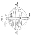
- L* means a value generally employed in a L*a*b* color representation system and is effective in representing a color by numeric values.
- a three-dimensional concept of such system is schematically shown in Fig. 1.
- a* and b* in horizontal axes represent a hue in combination.
- the hue means a scaled value of colors such as red, yellow, green, blue, purple etc.
- L* in a vertical axis indicates lightness, indicating a level of brightness of a color to be compared, regardless of the hue.
- a* and b* respectively indicate directions of color, and a* indicates a red-green direction while b* indicates a yellow-blue direction.
- a hue angle H indicates, for example for a color positioned at a point x(a*, b*) on an a*-b* coordinate system, an angle which a line segment connecting the original point and the point x(a*, b*) forms to a positive direction of the a* axis in the counterclockwise direction therefrom.
- the hue angle can easily represent a specified hue independently from the lightness.
- the a*, b*, c* and L* values of a cyan toner can be determined for example in the following manner.
- the toner is charged in a commercially available plain-paper full-color copying apparatus (color laser copying apparatus CLC1150; manufactured by Canon Inc.), and, with a plain paper (color laser copier paper TKCLA4; manufactured by Canon Inc.) as an image receiving material, an image of 200 lpi and 16 gradation levels is formed by changing the toner amount on the paper.
- the a*, b*, c* and L* values of the obtained image are measured with SpectroScan Transmission (manufactured by GretagMacbeth Inc.).
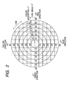
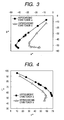
- a* and b* values are respectively plotted on the abscissa and the ordinate to obtain an a*-b* coordinate chart, on which a* values at b* of -20 and - 30 are determined.
- a representative result of measurement is shown in Fig. 3.
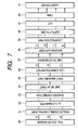
- the c* value is determined from the foregoing equation (2), and the c* and L* values are respectively plotted on the abscissa and the ordinate to obtain an L*-c* coordinate chart, on which L* value at c* of 30 is determined.
- a representative result of measurement is shown in Fig. 4.
- a hypochromic cyan toner having an a* value (a-1) within a range from -19 to -30 at a b* value of -20 and an a* value (a-2) within a range from -29 to -45 at a b* value of -30
- a hyperchromic cyan toner having an a* value (a-3) within a range from -7 to -18 at a b* value of -20 and an a* value (a-4) within a range from -10 to -28 at a b* value of -30.
- a modified apparatus of a configuration shown in Fig. 5 was prepared, based on the aforementioned color laser copying apparatus CLC1150 (manufactured by Canon Inc.).
- CLC1150 manufactured by Canon Inc.
- Fig. 5 there are provided a printer portion A, and an image reading portion (image scanner) mounted on the printer portion A.
- an original reading unit 21 is constituted of an original illuminating lamp 21a, a short-focus lens array 21b, a CCD sensor 21c etc.
- the image reading unit 21 In response to depression of an unillustrated copy button, the image reading unit 21 is driven forward under and along the original supporting glass 20, from a home position at the left side thereof to the right side and reversed upon arrival at a predetermined end point of reciprocating motion to the starting home position.
- the downward image surface of the original G set on the original supporting glass 20 is illuminated and scanned in succession from the left hand side to the right hand side, and the scanning illuminating light reflected from the original surface enters and is focused on the CCD sensor 21c through the short-focus lens array 21b.
- the CCD sensor 21c is constituted of a light receiving portion, a transfer portion and an output portion which are not illustrated, and in which a light signal is converted in the light receiving portion into a charge signal and transferred in the transfer portion in succession and in synchronization with clock pulses to the output portion, which converts the charge signal into a voltage signal for output after amplification and conversion to a low impedance.
- An analog signal thus obtained is converted by a known image processing into a digital signal for output to the printer portion A. In this manner the image information of the original G is photoelectrically read by the image reading portion B as time-sequential electrical digital pixel signal (image signal).
- Fig. 7 shows a block diagram of image processing.
- an image signal outputted from a full-color sensor 21c is supplied to an analog signal control part 51 for gain and offset regulations, then converted in an A/D converter 52 into color components, for example RGB digital signals of 8 bits (levels 0 - 255; 256 gradation levels), and is subjected, in a shading correction part 53, to a known shading correction for optimizing the gain of each CCD sensor cell, utilizing a signal obtained by reading a reference white board (not shown), in order to eliminate the sensitivity fluctuation within a linear array of the CCD sensor cells.
- a line delay part 54 corrects a spatial aberration included in the image signal outputted from the shading correction part 53.
- Such spatial aberration is generated by a fact that the line sensors constituting the full-color sensor 21c are arranged with a mutually predetermined distance in the sub scanning direction. More specifically, R (red) and G (green) color component signals are line delayed in the sub scanning direction with respect to B (blue) color component signal, whereby the three color component signals are synchronized in phase.
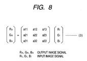
- An input masking part 55 transforms the color space of the image signal outputted from the line delay part 54, by a matrix calculation shown in an equation (3) in Fig. 8, into a standard NTSC color space. In this manner, the color space of each color component signal from the full-color sensor 40, determined by the spectral characteristics of a filter for each color component, is transformed into the standard NTSC color space.
- a LOG conversion part 56 constituted for example of a look-up table (LUT) stored in a ROM or the like, converts the RGB lightness signals from the input masking part 55 into CMY density signals.
- a line delay memory 57 delays the image signal from the LOG conversion part 56 during a period (line delay period) in which a black character discrimination part (not shown) generates control signals UCR, FILTER, SEN etc. from the output of the input masking part 55.
- a masking-UCR part 58 extracts a black component signal K from the image signal outputted from the line delay memory 57, also applies, on the YMCK signals, a matrix calculation for correction of a color turbidity in color recording materials used in the printer portion, and outputs color component image signals for example of 8 bits, in the order of M, C, Y and K for each reading operation of the reader portion. Matrix coefficients used in the matrix calculation are set by a CPU (not shown).
- a ⁇ correction part 59 applies a density correction on the image signal outputted from the masking-UCR part 58, in order to match the image signal with the ideal gradation characteristics of the printer portion.
- An output filter (spatial filter process part) 60 applies an edge enhancement or a smoothing process on the image signal from the ⁇ correction part 59, according to a control signal from the CPU.
- An LUT 61 for matching the density of the output image with that of the original image, is constituted for example of a RAM and includes a conversion table set by the CPU.
- a pulse width modulator (PWM) 62 outputs a pulse signal of a pulse width corresponding to the level of the input image signal, and such pulse signal is supplied to a laser driver 41 for driving a semiconductor laser (laser light source).
- the present image forming apparatus is equipped with a pattern generator (not shown) in which a gradation pattern is registered whereby a direct signal transfer to the pulse width modulator 62 is made possible.
- An exposure apparatus 3 applies a laser scan exposure L to the surface of a photosensitive member 1 based on the image signal entered from the image reading unit 21, thereby forming an electrostatic latent image.
- Fig. 9 schematically shows the configuration of the exposure apparatus 3.
- a solid laser element 25 is turned on/off at a predetermined timing by a light emission signal generator 24, based on the image signal entered from the image reading unit 21.
- the laser beam emitted from the solid laser element 25 and constituting an optical signal, is converted by a collimating lens system 26 into a substantially parallel light beam, which is then put into a scanning motion, by a rotary polygon mirror 22 rotated at a high speed in a direction c, along a longitudinal direction indicated by an arrow d of the photosensitive member 1 and is focused as a laser spot on the surface thereof through an f ⁇ lens group 23 and reflecting mirrors (cf. Fig. 1).
- Such laser scanning forms an exposure distribution on the surface of the photosensitive member 1 corresponding to a scan line, and an exposure distribution corresponding to the image signal can be obtained on the surface of the photosensitive member 1 by a scrolling of a predetermined amount of the surface of the photosensitive member 1 in the vertical direction for each scan.
- a developing apparatus 10 is provided, as shown in Fig. 10, with developing devices 411a, 411b, 412a, 412b, 413 and 414 into which respectively introduced are a developer containing a cyan toner a, a developer containing a cyan toner b, developers respectively containing magenta toners a and b, a developer containing a yellow toner and a developer containing a black toner, and develops the electrostatic latent image formed on the photosensitive member 1 serving as the electrostatic latent image bearing member by a magnetic brush development method, whereby a toner image of each color is formed on the photosensitive member 1.
- a two-component developing device as shown in Fig. 6 is a preferable example.
- a two-component developing device is provided with a developing sleeve 30 rotated in a direction e, in which a magnet roller 31 is provided in fixed manner.
- a developing container 32 is provided with a regulating blade 33 for forming a thin layer of a developer T on the surface of the developing sleeve 30.
- the interior of the developer container 32 is divided by a partition 36 into a developing chamber (first chamber) R1 and an agitating chamber (second chamber) R2, and a toner hopper 34 is positioned above the agitating chamber R2.
- a developing chamber first chamber
- an agitating chamber second chamber
- carrying screws 37, 38 are respectively provided in the developing chamber R1 and the agitating chamber R2.
- the toner hopper 34 has a supply aperture 35 through which the toner t is dropped, at the toner replenishment, into the agitating chamber R2.
- the developing chamber R1 and the agitating chamber R2 contain a developer T formed by a mixture of the aforementioned toner particles and magnetic carrier particles.
- the developer T in the developing chamber R1 is carried by the rotation of the carrying screw 37 along the longitudinal direction of the developing sleeve 30. Also the developer T in the agitating chamber R2 is carried by the rotation of the carrying screw 38 along the longitudinal direction of the developing sleeve 30. The developer carrying direction by the carrying screw 38 is opposite to that by the carrying screw 37.
- the partition 36 has apertures (not shown) at a front side and a rear side in the perpendicular direction to the plane of drawing, and the developer T carried by the carrying screw 37 is transferred through one of such apertures to the carrying screw 38, while the developer T carried by the carrying screw 38 is transferred through the other of such apertures to the carrying screw 37.
- the toner is charged, by a friction with the magnetic particles, in a polarity for developing the latent image.
- a magnetic brush formed by the developer T carried on the developing sleeve 30 is brought into contact, at the developing portion C, with the photosensitive member rotated in a direction a (clockwise), whereby the electrostatic latent image is developed in this developing portion C.
- a power supply (not shown) applies a vibrating bias voltage, formed by superposing a DC voltage with an AC voltage.
- a dark potential (potential of non-exposed area) and a light potential (potential of exposed area) of the latent image are situated between the maximum and minimum values of such vibrating bias voltage.
- an AC electric field with alternating directions is formed in the developing portion C.
- the toner and the carrier vibrate vigorously, and the toner overcomes the electrostatic restraint by the developing sleeve 30 and the carrier and is deposited corresponding to the latent image, namely in the light area on the surface of the photosensitive member 1.
- a difference between the maximum and minimum values (peak-to-peak voltage) of the vibrating bias voltage is preferably 1 to 5 kV, and a rectangular wave of 2 kV was employed in the present embodiment. Also a frequency is preferably 1 to 10 kHz, and 2 kHz was used in the present embodiment.
- the wave shape of the vibrating bias voltage is not limited to a rectangular wave, but can also be a sinusoidal wave, a triangular wave etc.
- the aforementioned DC voltage component has a value between the dark potential and the light potential of the electrostatic latent image, but is preferably closer to the dark potential than to the absolute minimum light potential, in order to prevent adhesion of fogging toner in the dark potential area.
- a light potential of -200 V and a DC component of the developing bias of -500 V were employed for a dark potential of -700 V.
- a minimum gap between the developing sleeve 30 and the photosensitive member 1 is preferably from 0.2 to 1 mm, and was selected as 0.5 mm in the present embodiment.
- an amount of the developer T, regulated by the regulating blade 33 and carried to the developing portion C, is preferably such that the magnetic brush of the developer T, formed by a magnetic field induced in the developing portion C by a developing magnetic pole S1 of the magnet roller 31, has a height of 1.2 to 3 times of the minimum gap between the developing sleeve 30 and the photosensitive member 1, on the surface of the developing sleeve 30 in a state without the photosensitive member 1. It was selected as 700 ⁇ m in the present embodiment.
- the developing magnetic pole S1 of the magnet. roller 31 is provided in a position opposed to the developing portion C, and the magnetic brush of the developer T is formed by the developing magnetic field induced in the developing portion C by such developing magnetic pole S1 and is brought into contact with the photosensitive member 1, thereby developing the dot-distributed electrostatic latent image.
- the magnetic brush of the developer T is formed by the developing magnetic field induced in the developing portion C by such developing magnetic pole S1 and is brought into contact with the photosensitive member 1, thereby developing the dot-distributed electrostatic latent image.
- An intensity of the developing magnetic field induced by the developing magnetic pole S1 on the surface of the developing sleeve 30 preferably has a peak value within a range of 5 ⁇ 10 -2 to 2 ⁇ 10 -1 (T).
- the magnet roller 31 has poles N1, N2, N3 and S2 in addition to the developing magnetic pole S1.
- the developer T scooped up by the pole N2 is carried through the pole S2 to the pole N1, and is subjected in the course to a thickness regulation by the regulating blade 33 to form a thin layer of the developer. Then the developer T, formed in a brush in the magnetic field of the developing magnetic pole S1 develops the electrostatic latent image on the photosensitive member 1. Thereafter, by a repulsive magnetic field between the poles N2 and N3, the developer T on the developing sleeve 30 drops into the developing chamber R1. The developer T having dropped into the developing chamber R1 is agitated and carried by the carrying screw 37.
- the intermediate transfer member and the transfer means can be constituted of ordinary materials.
- a transfer member 5 is constituted of a transfer sheet 5c, having for example a polyethylene terephthalate resin film on the surface and maintained under tension so as to contacted with or separated from the photosensitive member 1.
- the transfer member 5 is rotated in a direction as indicated by an arrow (clockwise).
- a transfer charger 5a, a separating charger 5b etc. are provided inside the transfer member 5.
- the photosensitive member 1 is rotated about a central shaft with a predetermined peripheral speed (process speed) in a direction indicated by an arrow a (counterclockwise direction), and is subjected, in the source such rotation by the primary charger 2, to a uniform charging step which is of a negative polarity in the present embodiment.
- the photosensitive member 1 is subjected to a scan exposure L with the laser beam, which is emitted from the exposure apparatus (laser scanning apparatus) 3 and which is modulated according to the image signal outputted from the image reading portion B to the printer portion A, whereby, on the photosensitive member 1, electrostatic latent images of respective colors corresponding to the image information of the original G photoelectrically read by the image reading portion B are formed in succession.
- the electrostatic latent images formed on the photosensitive member 1 are subjected to a reversal development by the aforementioned two-component magnetic brush method in the developing apparatus 4, and at first the developing device 411a is used to obtain a visible toner image of a first color.
- a transfer material P such as paper, contained in a sheet cassette 10 is advanced one by one by a sheet feed roller 11 or 12, then supplied to the transfer member 5 at predetermined timing by registration rollers 13, and is electrostatically attracted to the transfer member 5 by the function of an attraction roller 14.
- the transfer material P electrostatically attracted on the transfer member 5 is moved to a position opposed to the photosensitive member 1 by the rotation of the transfer member 5 in a direction indicated by an arrow (clockwise), and the transfer material P is given, on the back side thereof, a charge of a polarity opposite to that of the toner by the transfer charger 5a, whereby the toner image on the photosensitive member 1 is transferred onto the top side.
- transfer residual toner remaining on the photosensitive member 1, is removed by a cleaning apparatus 6 and is used for a next toner image formation.
- the electrostatic latent image on the photosensitive member 1 is developed in a similar manner, so that an cyan toner a image , a cyan toner b image, a magenta toner a image, a magenta toner b image, a yellow toner image and a black toner image, formed on the photosensitive member 1, are transferred by the transfer charger 5a onto the transfer material P on the transfer member 5 in superposition, thereby forming a full-color image.
- the transfer material P is separated by a separating charger 5b from the transfer member 5 and is conveyed by a conveyor belt 8 to a fixing apparatus 9.
- the transfer material P enters the fixing apparatus 9 with a speed of about 200 mm/sec, then is heated at about 160°C and pressed under a pressure of 70 kg between a fixing roller 9a (silicone rubber of a thickness of 2.4 mm, diameter: 60 mm, hardness: 79 (ASK-C load 1 kg)) and a pressure roller 9b (silicone rubber of a thickness of 1.8 mm, diameter: 60 mm, hardness: 81 (ASK-C load 1 kg)) to fix the full-color image on the surface, and is discharged by discharge rollers 15 onto a discharge tray 16.
- a fixing roller 9a silicone rubber of a thickness of 2.4 mm, diameter: 60 mm, hardness: 79 (ASK-C load 1 kg)
- a pressure roller 9b silicone rubber of a thickness of 1.8 mm, diameter:
- the surface of the photosensitive member 1 is subjected to a removal of the transfer residual toner by the cleaning apparatus 6; and further subjected to a charge elimination by a pre-exposure lamp 7, thereby being prepared for a next image formation.
- an image formation with hyperchromic-hypochromic toners of substantially same hues is executed utilizing a writing resolution for the hypochromic toner larger than that for the hyperchromic toner, thereby rendering screen lines less visible in a highlight area and stabilizing the density and the color in a high density area, so that a photograph-like image, for which the hyperchromic-hypochromic toners are often used, can be obtained in a visually preferable manner.
- the electrophotographic recording apparatus of the above-described embodiment includes a photoconductive image bearing member; charging means which uniformly charges the image bearing member; exposure means which effects an imagewise exposure on a surface of the image bearing member after charging thereby forming an electrostatic latent image; development means which adheres a toner onto the electrostatic latent image thereby forming a toner image; and transfer means which transfers the formed toner image onto a transfer material; wherein an image is formed with plural toners including a hyperchromic toner and a hypochromic toner of substantially same hues, and a writing resolution for an image for the hypochromic toner is made larger than a writing resolution for an image for the hyperchromic toner.
- means which separated the image density data into image data for hyperchromic toner and those for hypochromic toner, and the exposure means is so constructed as to form the electrostatic latent image according to thus separated image data. Also the development process for the hyperchromic toner and the development process for the hypochromic toner were so constructed as not to be multiplexed.
- an electrophotographic image recording apparatus apparatus including a photoconductive image bearing member, a charging apparatus for uniformly charging the image bearing member, an exposure apparatus for effecting an imagewise exposure on a surface of the image bearing member after charging thereby forming an electrostatic latent image, a development apparatus for adhering a toner onto the electrostatic latent image thereby forming a toner image, and a transfer member for transferring the formed toner image onto a final support member such as plain paper
- image formation is executed with a writing resolution for the hypochromic toner larger than a writing resolution for the hyperchromic toner.
Landscapes
- Physics & Mathematics (AREA)
- General Physics & Mathematics (AREA)
- Discrete Mathematics (AREA)
- Engineering & Computer Science (AREA)
- Multimedia (AREA)
- Signal Processing (AREA)
- Color Electrophotography (AREA)
- Control Or Security For Electrophotography (AREA)
- Fax Reproducing Arrangements (AREA)
Abstract
Description

Claims (6)
- An electrophotographic image recording apparatus for forming an image with a plurality of toners including a hyperchromic toner and a hypochromic toner of a substantially same hue, the apparatus comprising:wherein a writing resolution for an image for said hypochromic toner is larger than a writing resolution for an image for said hyperchromic toner.a photoconductive image bearing member;charging means which uniformly charges said photoconductive image bearing member;exposure means which effects an imagewise exposure on a surface of said photoconductive image bearing member after charging thereby forming an electrostatic latent image;development means which adheres a toner onto said electrostatic latent image thereby forming a toner image; andtransfer means which transfers the toner image formed by development means onto a transfer material;
- An apparatus according to claim 1, wherein said plural toners include a cyan color toner and a magenta color toner, and each of the cyan color toner and the magenta color toner includes two types of toners of respectively different densities.
- An apparatus according to claim 1, further comprising:wherein said exposure means forms an electrostatic latent image according to said separated image data.means which separates image density data into image data for a hyperchromic toner and image data for a hypochromic toner;
- An apparatus according to claim 1, wherein a developing process with the hypochromic toner and a developing process with the hyperchromic toner are not multiplexed.
- An electrophotographic image recording apparatus for forming an image with a plurality of toners including a hyperchromic toner and a hypochromic toner of a substantially same hue, the apparatus comprising:wherein a writing resolution for an image for said hypochromic toner is larger than a writing resolution for an image for said hyperchromic toner.a photoconductive image bearing member;a charging device adapted for uniformly charging said image bearing member;an exposure device adapted for effecting an imagewise exposure on a surface of said photoconductive image bearing member after charging thereby forming an electrostatic latent image;a development device adapted for adhering a toner onto the electrostatic latent image thereby forming a toner image; anda transfer device adapted for transferring the formed toner image onto a transfer material;
- An electrophotographic image recording method for forming an image with a plurality of toners including a hyperchromic toner and a hypochromic toner of a substantially same hue, the method comprising steps of:wherein a writing resolution for an image for the hypochromic toner is larger than a writing resolution for an image for the hyperchromic toner.uniformly charging a photoconductive image bearing member;effecting an imagewise exposure on a surface of the photoconductive image bearing member after charging thereby forming an electrostatic latent image;adhering a toner onto said electrostatic latent image thereby forming a toner image and transferring the formed toner image onto a transfer material;
Applications Claiming Priority (2)
| Application Number | Priority Date | Filing Date | Title |
|---|---|---|---|
| JP2003200421A JP4532858B2 (en) | 2003-07-23 | 2003-07-23 | Electrophotographic image recording device |
| JP2003200421 | 2003-07-23 |
Publications (2)
| Publication Number | Publication Date |
|---|---|
| EP1500989A1 true EP1500989A1 (en) | 2005-01-26 |
| EP1500989B1 EP1500989B1 (en) | 2008-10-15 |
Family
ID=33487638
Family Applications (1)
| Application Number | Title | Priority Date | Filing Date |
|---|---|---|---|
| EP04016103A Expired - Lifetime EP1500989B1 (en) | 2003-07-23 | 2004-07-08 | Electrophotographic image recording apparatus and method therefore avoiding streak formation when using light and dark toner of the same hue |
Country Status (6)
| Country | Link |
|---|---|
| US (1) | US7315712B2 (en) |
| EP (1) | EP1500989B1 (en) |
| JP (1) | JP4532858B2 (en) |
| KR (1) | KR100558246B1 (en) |
| CN (1) | CN100485543C (en) |
| DE (1) | DE602004017088D1 (en) |
Cited By (1)
| Publication number | Priority date | Publication date | Assignee | Title |
|---|---|---|---|---|
| WO2006028230A1 (en) | 2004-09-07 | 2006-03-16 | Canon Kabushiki Kaisha | Image processing apparatus with six colour toners |
Families Citing this family (2)
| Publication number | Priority date | Publication date | Assignee | Title |
|---|---|---|---|---|
| JP2006237856A (en) * | 2005-02-23 | 2006-09-07 | Ricoh Co Ltd | Image processing apparatus, image processing method, program for causing computer to execute the method, and recording medium |
| JP2007241068A (en) * | 2006-03-10 | 2007-09-20 | Fuji Xerox Co Ltd | Image forming apparatus |
Citations (4)
| Publication number | Priority date | Publication date | Assignee | Title |
|---|---|---|---|---|
| EP0401023A2 (en) * | 1989-06-01 | 1990-12-05 | Canon Kabushiki Kaisha | Image recording system and apparatus therefor |
| JP2000347476A (en) * | 1999-04-02 | 2000-12-15 | Canon Inc | Image forming apparatus and image forming method |
| JP2001290319A (en) * | 2000-04-07 | 2001-10-19 | Konica Corp | Image forming device |
| EP1376255A2 (en) * | 2002-05-20 | 2004-01-02 | Canon Kabushiki Kaisha | Toner kit, method for forming a toner image, and image forming apparatus |
Family Cites Families (12)
| Publication number | Priority date | Publication date | Assignee | Title |
|---|---|---|---|---|
| JPS5839468A (en) | 1981-09-04 | 1983-03-08 | Nippon Telegr & Teleph Corp <Ntt> | Gradated image recording system for ink jet recording |
| JPH1184764A (en) | 1997-09-10 | 1999-03-30 | Fuji Xerox Co Ltd | Digital image forming method and device therefor |
| JP3728129B2 (en) | 1999-02-09 | 2005-12-21 | キヤノン株式会社 | Image forming apparatus |
| JP2000305339A (en) | 1999-04-22 | 2000-11-02 | Konica Corp | Image forming, image forming device, and electrostatic latent image developing toner used for the device |
| JP2001096768A (en) | 1999-10-01 | 2001-04-10 | Canon Inc | Ink jet recording apparatus and ink jet recording method |
| US6498910B2 (en) | 2000-04-07 | 2002-12-24 | Konica Corporation | Image forming with light and dark hue toners |
| JP2002055500A (en) * | 2000-08-11 | 2002-02-20 | Konica Corp | Image forming device |
| JP2002254624A (en) | 2001-03-05 | 2002-09-11 | Ricoh Co Ltd | Ink jet recording device |
| JP2002341606A (en) * | 2001-05-15 | 2002-11-29 | Konica Corp | Image forming apparatus |
| JP2003154641A (en) * | 2001-11-20 | 2003-05-27 | Konica Corp | Ink jet recorder for medical use |
| JP4120209B2 (en) * | 2001-11-26 | 2008-07-16 | コニカミノルタホールディングス株式会社 | Image recording apparatus, medical image recording apparatus, and medical image system |
| JP4012015B2 (en) | 2002-08-29 | 2007-11-21 | キヤノン株式会社 | Image forming apparatus |
-
2003
- 2003-07-23 JP JP2003200421A patent/JP4532858B2/en not_active Expired - Fee Related
-
2004
- 2004-06-29 US US10/878,049 patent/US7315712B2/en not_active Expired - Fee Related
- 2004-07-08 DE DE602004017088T patent/DE602004017088D1/en not_active Expired - Lifetime
- 2004-07-08 EP EP04016103A patent/EP1500989B1/en not_active Expired - Lifetime
- 2004-07-22 KR KR1020040057020A patent/KR100558246B1/en not_active Expired - Fee Related
- 2004-07-23 CN CNB2004100708558A patent/CN100485543C/en not_active Expired - Fee Related
Patent Citations (4)
| Publication number | Priority date | Publication date | Assignee | Title |
|---|---|---|---|---|
| EP0401023A2 (en) * | 1989-06-01 | 1990-12-05 | Canon Kabushiki Kaisha | Image recording system and apparatus therefor |
| JP2000347476A (en) * | 1999-04-02 | 2000-12-15 | Canon Inc | Image forming apparatus and image forming method |
| JP2001290319A (en) * | 2000-04-07 | 2001-10-19 | Konica Corp | Image forming device |
| EP1376255A2 (en) * | 2002-05-20 | 2004-01-02 | Canon Kabushiki Kaisha | Toner kit, method for forming a toner image, and image forming apparatus |
Non-Patent Citations (2)
| Title |
|---|
| PATENT ABSTRACTS OF JAPAN vol. 2000, no. 15 6 April 2001 (2001-04-06) * |
| PATENT ABSTRACTS OF JAPAN vol. 2002, no. 02 2 April 2002 (2002-04-02) * |
Cited By (2)
| Publication number | Priority date | Publication date | Assignee | Title |
|---|---|---|---|---|
| WO2006028230A1 (en) | 2004-09-07 | 2006-03-16 | Canon Kabushiki Kaisha | Image processing apparatus with six colour toners |
| US7603064B2 (en) | 2004-09-07 | 2009-10-13 | Canon Kabushiki Kaisha | Unit for tone-processing image data using screen pattern with different screen angles for toners of same hue and different density |
Also Published As
| Publication number | Publication date |
|---|---|
| CN100485543C (en) | 2009-05-06 |
| KR100558246B1 (en) | 2006-03-10 |
| US7315712B2 (en) | 2008-01-01 |
| CN1577151A (en) | 2005-02-09 |
| JP2005043451A (en) | 2005-02-17 |
| EP1500989B1 (en) | 2008-10-15 |
| JP4532858B2 (en) | 2010-08-25 |
| KR20050011716A (en) | 2005-01-29 |
| DE602004017088D1 (en) | 2008-11-27 |
| US20050019681A1 (en) | 2005-01-27 |
Similar Documents
| Publication | Publication Date | Title |
|---|---|---|
| US6498910B2 (en) | Image forming with light and dark hue toners | |
| US6879788B2 (en) | Image forming apparatus with density detecting means | |
| US6327450B1 (en) | Image forming apparatus and image forming method using color toner | |
| EP0817468B1 (en) | Method and apparatus for producing color images | |
| US5157483A (en) | Multicolor image forming method and apparatus | |
| US20060269330A1 (en) | Image forming apparatus capable of accomplishing uniformity in glossiness | |
| JPH04204763A (en) | Digital image forming device | |
| US7715741B2 (en) | Image forming apparatus with a toner image density feature and related method | |
| EP1500989B1 (en) | Electrophotographic image recording apparatus and method therefore avoiding streak formation when using light and dark toner of the same hue | |
| US7343112B2 (en) | Image forming apparatus using hypochromatic toner and hyperchromatic toner | |
| JP3738124B2 (en) | Multicolor image forming apparatus | |
| US6538683B2 (en) | Image forming apparatus and a control method of an image forming apparatus | |
| JP4095637B2 (en) | Image forming apparatus | |
| JP2002139882A (en) | Color image forming device | |
| JP4209704B2 (en) | Image forming apparatus and image forming method | |
| JPH0228867B2 (en) | ||
| JP4890910B2 (en) | Image forming apparatus | |
| JPWO1996024091A1 (en) | color electrophotographic printer | |
| JP2008040030A (en) | Image data correction method | |
| JPH0784431A (en) | Color image forming device | |
| JP2005091956A (en) | Image forming apparatus | |
| JP2002326394A (en) | Image forming device |
Legal Events
| Date | Code | Title | Description |
|---|---|---|---|
| PUAI | Public reference made under article 153(3) epc to a published international application that has entered the european phase |
Free format text: ORIGINAL CODE: 0009012 |
|
| AK | Designated contracting states |
Kind code of ref document: A1 Designated state(s): AT BE BG CH CY CZ DE DK EE ES FI FR GB GR HU IE IT LI LU MC NL PL PT RO SE SI SK TR |
|
| AX | Request for extension of the european patent |
Extension state: AL HR LT LV MK |
|
| 17P | Request for examination filed |
Effective date: 20050726 |
|
| AKX | Designation fees paid |
Designated state(s): DE FR GB |
|
| 17Q | First examination report despatched |
Effective date: 20061115 |
|
| RTI1 | Title (correction) |
Free format text: ELECTROPHOTOGRAPHIC IMAGE RECORDING APPARATUS AND METHOD THEREFORE AVOIDING STREAK FORMATION WHEN USING LIGHT AND DARK TONER OF THE SAME HUE |
|
| GRAP | Despatch of communication of intention to grant a patent |
Free format text: ORIGINAL CODE: EPIDOSNIGR1 |
|
| GRAS | Grant fee paid |
Free format text: ORIGINAL CODE: EPIDOSNIGR3 |
|
| GRAA | (expected) grant |
Free format text: ORIGINAL CODE: 0009210 |
|
| AK | Designated contracting states |
Kind code of ref document: B1 Designated state(s): DE FR GB |
|
| REG | Reference to a national code |
Ref country code: GB Ref legal event code: FG4D |
|
| REF | Corresponds to: |
Ref document number: 602004017088 Country of ref document: DE Date of ref document: 20081127 Kind code of ref document: P |
|
| PLBE | No opposition filed within time limit |
Free format text: ORIGINAL CODE: 0009261 |
|
| STAA | Information on the status of an ep patent application or granted ep patent |
Free format text: STATUS: NO OPPOSITION FILED WITHIN TIME LIMIT |
|
| 26N | No opposition filed |
Effective date: 20090716 |
|
| PGFP | Annual fee paid to national office [announced via postgrant information from national office to epo] |
Ref country code: DE Payment date: 20140731 Year of fee payment: 11 |
|
| PGFP | Annual fee paid to national office [announced via postgrant information from national office to epo] |
Ref country code: GB Payment date: 20140724 Year of fee payment: 11 Ref country code: FR Payment date: 20140728 Year of fee payment: 11 |
|
| REG | Reference to a national code |
Ref country code: DE Ref legal event code: R119 Ref document number: 602004017088 Country of ref document: DE |
|
| GBPC | Gb: european patent ceased through non-payment of renewal fee |
Effective date: 20150708 |
|
| PG25 | Lapsed in a contracting state [announced via postgrant information from national office to epo] |
Ref country code: GB Free format text: LAPSE BECAUSE OF NON-PAYMENT OF DUE FEES Effective date: 20150708 Ref country code: DE Free format text: LAPSE BECAUSE OF NON-PAYMENT OF DUE FEES Effective date: 20160202 |
|
| REG | Reference to a national code |
Ref country code: FR Ref legal event code: ST Effective date: 20160331 |
|
| PG25 | Lapsed in a contracting state [announced via postgrant information from national office to epo] |
Ref country code: FR Free format text: LAPSE BECAUSE OF NON-PAYMENT OF DUE FEES Effective date: 20150731 |