EP1500924A1 - Method for detecting soot during real time operation in diesel engine lubricant - Google Patents
Method for detecting soot during real time operation in diesel engine lubricant Download PDFInfo
- Publication number
- EP1500924A1 EP1500924A1 EP04016062A EP04016062A EP1500924A1 EP 1500924 A1 EP1500924 A1 EP 1500924A1 EP 04016062 A EP04016062 A EP 04016062A EP 04016062 A EP04016062 A EP 04016062A EP 1500924 A1 EP1500924 A1 EP 1500924A1
- Authority
- EP
- European Patent Office
- Prior art keywords
- soot
- angle
- plot
- lubricant
- method defined
- Prior art date
- Legal status (The legal status is an assumption and is not a legal conclusion. Google has not performed a legal analysis and makes no representation as to the accuracy of the status listed.)
- Withdrawn
Links
- 239000004071 soot Substances 0.000 title claims abstract description 32
- 238000000034 method Methods 0.000 title claims description 14
- 239000010705 motor oil Substances 0.000 title claims description 13
- 238000005259 measurement Methods 0.000 claims abstract description 5
- 239000012530 fluid Substances 0.000 claims description 5
- 238000012544 monitoring process Methods 0.000 claims description 3
- 238000009825 accumulation Methods 0.000 claims description 2
- 238000002847 impedance measurement Methods 0.000 claims 1
- 239000000523 sample Substances 0.000 abstract description 19
- 239000000314 lubricant Substances 0.000 abstract description 18
- 238000001566 impedance spectroscopy Methods 0.000 description 4
- 239000003921 oil Substances 0.000 description 4
- 238000012545 processing Methods 0.000 description 4
- OKTJSMMVPCPJKN-UHFFFAOYSA-N Carbon Chemical compound [C] OKTJSMMVPCPJKN-UHFFFAOYSA-N 0.000 description 1
- 238000005033 Fourier transform infrared spectroscopy Methods 0.000 description 1
- 238000004458 analytical method Methods 0.000 description 1
- 238000007664 blowing Methods 0.000 description 1
- 238000004364 calculation method Methods 0.000 description 1
- 229910052799 carbon Inorganic materials 0.000 description 1
- 238000002485 combustion reaction Methods 0.000 description 1
- 239000000470 constituent Substances 0.000 description 1
- 230000002939 deleterious effect Effects 0.000 description 1
- 239000010710 diesel engine oil Substances 0.000 description 1
- 230000005284 excitation Effects 0.000 description 1
- 238000011005 laboratory method Methods 0.000 description 1
- 238000004519 manufacturing process Methods 0.000 description 1
- 238000002156 mixing Methods 0.000 description 1
- 238000012986 modification Methods 0.000 description 1
- 230000004048 modification Effects 0.000 description 1
- 230000003287 optical effect Effects 0.000 description 1
- 239000002245 particle Substances 0.000 description 1
- 230000009467 reduction Effects 0.000 description 1
- 238000000611 regression analysis Methods 0.000 description 1
- 230000035945 sensitivity Effects 0.000 description 1
- 239000007787 solid Substances 0.000 description 1
- 238000002411 thermogravimetry Methods 0.000 description 1
- 230000000007 visual effect Effects 0.000 description 1
Images

Classifications
-
- G—PHYSICS
- G01—MEASURING; TESTING
- G01N—INVESTIGATING OR ANALYSING MATERIALS BY DETERMINING THEIR CHEMICAL OR PHYSICAL PROPERTIES
- G01N33/00—Investigating or analysing materials by specific methods not covered by groups G01N1/00 - G01N31/00
- G01N33/26—Oils; Viscous liquids; Paints; Inks
- G01N33/28—Oils, i.e. hydrocarbon liquids
- G01N33/2888—Lubricating oil characteristics, e.g. deterioration
-
- G—PHYSICS
- G01—MEASURING; TESTING
- G01N—INVESTIGATING OR ANALYSING MATERIALS BY DETERMINING THEIR CHEMICAL OR PHYSICAL PROPERTIES
- G01N27/00—Investigating or analysing materials by the use of electric, electrochemical, or magnetic means
- G01N27/02—Investigating or analysing materials by the use of electric, electrochemical, or magnetic means by investigating impedance
Definitions
- the present invention relates to detecting the accumulation of soot or carbon particles in diesel engine lubricant. It has been found that recent reductions in mandated limits for vehicle engine exhaust emissions have required fitting diesel engines for use with exhaust gas recirculation (EGR) valves to dilute the fuel-air charge ratio. This has resulted in changes in combustion chemistry and an increase in the rate of build-up of soot blowing past the engine piston rings and contaminating the engine lubricant oil.
- EGR exhaust gas recirculation
- soot above a threshold concentration has been found to render the engine lubricant unable to effectively perform its function and engine damage becomes imminent.
- soot concentration in engine lubricant were laboratory techniques which required taking a sample of the engine oil to a laboratory for analysis and performing Thermo Gravimetric Analysis or using optical techniques such as Fourier Transform Infrared Spectroscopy to determine the amount of soot present in the lubricant fluid. This has proven to be prohibitively costly and time consuming and thus virtually unworkable when it is necessary to monitor the oil condition of a diesel engine during operation in service.
- Impedance Spectroscopy it is known to use Impedance Spectroscopy in monitoring the condition of engine lubricant fluid during real time operation in engines such as shown and described in U.S. Patents 6,278,281, 6,377,052 and 6,380,746.
- the aforesaid technique utilizes differential Impedance Spectroscopy to detect depletion of the lubricant constituents added by the manufacturer during blending.
- the impedance spectroscopy algorithms set forth in the aforesaid patents have been found unable to monitor soot in diesel engine lubricant.
- the present invention utilizes an electrical probe to provide an electrical signal indicative of the soot concentration in the lubricant fluid or oil of a diesel engine during real time operation by employing a novel procedure for analyzing the signal utilizing impedance spectroscopy.
- An electrical probe having a pair of electrodes is immersed in the lubricant in the engine sump and an alternating current of relatively low voltage of varying frequency is applied to the probe electrodes and the current and phase angle are measured at selected intervals over the range of frequencies.
- the resistive and reactive components of impedance are then computed and plotted in a Nyquist plot of reactive impedance versus resistive impedance. The center of curvature of the semicircular region of the plot between the origin and the minimum occurring value of reactive impedance is then determined.
- the angle of depression of the center of curvature from the origin below the X-axis is then computed and plotted for as a function of soot concentration for readings taken with samples of lubricant having a known concentration.
- An algorithm is then derived from the plot which may be programmed into an electronic controller for comparing the computed depression angle at any given instant with that of known values to determine the corresponding soot concentration at that time.
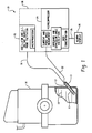
- FIG. 1 is a pictorial schematic of a system employing the present invention
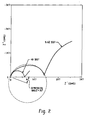
- FIG. 2 is a Nyquist plot illustrating the method of determining the depression angle
- FIG. 3 is a plot of depression angle as a function of soot concentration for two sets of lubricant samples having different known concentrations of soot.
- the system of the present invention is indicated generally at 10 and includes a probe 12 inserted into the crankcase or sump of a diesel engine 14 filled with lubricant to a level indicated at 16.
- the probe may have any suitable electrode configuration; however, in the present practice of the invention it has been found satisfactory to use a pair of concentric tubularly configured concentric electrodes denoted by reference numerals 11, 13 in FIG. 1.
- This probe may be configured as set forth in co-pending application Serial No. 10/060,107 filed January 31, 2002, entitled "Probe Assembly For Fluid Condition Monitor And Method Of Making Same" and assigned to the assignee of the present application.
- the probe 12 has one electrode excited along line 18 with a relatively low voltage AC current from a controller 20 which may include an oscillator and microprocessor for providing a relatively low voltage source of AC current to the probe.
- the probe current measured by connection through line 22 to an electronic signal processing unit 24 which may include a microcomputer and which measures the amplitude and phase angle of the current through probe 12 and performs calculations thereon as will hereinafter be described.
- an electronic signal processing unit 24 may include a microcomputer and which measures the amplitude and phase angle of the current through probe 12 and performs calculations thereon as will hereinafter be described.
- a signal is sent through line 26 to an alarm/display 28 for alerting the engine operator.
- the probe 12 has a pair of electrodes disposed in generally parallel closely spaced arrangement which are immersed in the lubricant in the sump of the engine and that the current measure flows from one electrode through lubricant to the other electrode to complete the current path along lead 22 to the signal processor 24.
- controller 20 and signal processing unit 24 may be located remotely from the engine 14 and combined into a common packaged unit as illustrated in dashed outline in FIG. 1 and denoted by reference numeral 30.
- the current and phase angle are measured and, at selected intervals, as for example, intervals of 100 - 200 Hertz and the reactive impedance and resistive impedance are computed and the data pairs are plotted with the reactive impedance denoted Z" as the ordinates and the resistive impedance denoted Z' as abscissae in a manner known as a Nyquist plot as illustrated in FIG. 2.
- the center of the semi-circular curvature of the region of the graph between the origin and the minimal value of Z" is then determined from the plots and the angle of depression of the center of curvature formed by a line from the origin through the center of curvature is then computed.
- the angle of depression is illustrated in FIG. 2 and is denoted by the symbol ⁇ .
- the angle of depression is small for diesel engine lubricant containing no soot; and, at a maximum value of about 9.6% soot concentration, the angle of depression ⁇ has been determined to be about 26 degrees.
- the current measurements of the probe may be utilized to determine the percentage of soot concentration in the lubricant because there is enough variation in the depression angle ⁇ to provide a satisfactory degree of sensitivity or resolution of the sensor to the soot concentration over the range of interest.
- the depression angle ⁇ as measured for two groups of samples of diesel lubricant oil having known concentrations of soot are plotted with the data for each sample set indicated by a distinct legend.
- the data in each of the two sets of samples were taken separately from lubricant drains from two running engines sequentially at intervals of continuously increasing lubricant stressing.
- a curve is then fit through the data by any suitable technique as, for example, multiple regression analysis; and, such a curve was fitted and is shown in solid outline, with upper and lower 95% confidence limits shown in dashed outline.
- the technique of the present invention thus permits the use of the depression angle ⁇ as an analog of the soot concentration and a curve can be generated from measured data.
- the signal processing unit 24 can be programmed with an algorithm or equation for the curve; and, for a given angle ⁇ determined from probe current measurements, a corresponding value of percentage of soot determined by the controller.
- the present invention thus permits measurement of soot concentration in diesel engine oil during operation in real time with a sensor that provides a continuous electrical signal output.
- the system employing the present invention may be designed as shown in FIG. 1 to have an alarm or display providing a visual or audible indication that the maximum allowable percentage of soot has been reached in the engine lubricant.
- the alarm or display it has been found that when the soot concentration in the lubricant reaches a deleterious level it is possible to have the alarm or display set to indicate that the lubricant is no longer capable of effectively performing its function.
Landscapes
- Chemical & Material Sciences (AREA)
- Health & Medical Sciences (AREA)
- Life Sciences & Earth Sciences (AREA)
- Engineering & Computer Science (AREA)
- General Health & Medical Sciences (AREA)
- Chemical Kinetics & Catalysis (AREA)
- Pathology (AREA)
- Immunology (AREA)
- General Physics & Mathematics (AREA)
- Physics & Mathematics (AREA)
- Analytical Chemistry (AREA)
- Biochemistry (AREA)
- Oil, Petroleum & Natural Gas (AREA)
- Medicinal Chemistry (AREA)
- Food Science & Technology (AREA)
- General Chemical & Material Sciences (AREA)
- Electrochemistry (AREA)
- Investigating Or Analyzing Materials By The Use Of Electric Means (AREA)
- Lubrication Details And Ventilation Of Internal Combustion Engines (AREA)
Abstract
Description
- The present invention relates to detecting the accumulation of soot or carbon particles in diesel engine lubricant. It has been found that recent reductions in mandated limits for vehicle engine exhaust emissions have required fitting diesel engines for use with exhaust gas recirculation (EGR) valves to dilute the fuel-air charge ratio. This has resulted in changes in combustion chemistry and an increase in the rate of build-up of soot blowing past the engine piston rings and contaminating the engine lubricant oil.
- The presence of soot above a threshold concentration has been found to render the engine lubricant unable to effectively perform its function and engine damage becomes imminent.
- Heretofore, available means for determining soot concentration in engine lubricant were laboratory techniques which required taking a sample of the engine oil to a laboratory for analysis and performing Thermo Gravimetric Analysis or using optical techniques such as Fourier Transform Infrared Spectroscopy to determine the amount of soot present in the lubricant fluid. This has proven to be prohibitively costly and time consuming and thus virtually unworkable when it is necessary to monitor the oil condition of a diesel engine during operation in service.
- It is known to use Impedance Spectroscopy in monitoring the condition of engine lubricant fluid during real time operation in engines such as shown and described in U.S. Patents 6,278,281, 6,377,052 and 6,380,746. The aforesaid technique utilizes differential Impedance Spectroscopy to detect depletion of the lubricant constituents added by the manufacturer during blending. However the impedance spectroscopy algorithms set forth in the aforesaid patents have been found unable to monitor soot in diesel engine lubricant.
- Thus, it has been desired to find a way or means of monitoring diesel engine lubricant during real time operation of the engine and in particular to monitor the concentration of soot.
- The present invention utilizes an electrical probe to provide an electrical signal indicative of the soot concentration in the lubricant fluid or oil of a diesel engine during real time operation by employing a novel procedure for analyzing the signal utilizing impedance spectroscopy. An electrical probe having a pair of electrodes is immersed in the lubricant in the engine sump and an alternating current of relatively low voltage of varying frequency is applied to the probe electrodes and the current and phase angle are measured at selected intervals over the range of frequencies. The resistive and reactive components of impedance are then computed and plotted in a Nyquist plot of reactive impedance versus resistive impedance. The center of curvature of the semicircular region of the plot between the origin and the minimum occurring value of reactive impedance is then determined. The angle of depression of the center of curvature from the origin below the X-axis is then computed and plotted for as a function of soot concentration for readings taken with samples of lubricant having a known concentration. An algorithm is then derived from the plot which may be programmed into an electronic controller for comparing the computed depression angle at any given instant with that of known values to determine the corresponding soot concentration at that time.
- FIG. 1 is a pictorial schematic of a system employing the present invention;
- FIG. 2 is a Nyquist plot illustrating the method of determining the depression angle; and,
- FIG. 3 is a plot of depression angle as a function of soot concentration for two sets of lubricant samples having different known concentrations of soot.
- The system of the present invention is indicated generally at 10 and includes a
probe 12 inserted into the crankcase or sump of adiesel engine 14 filled with lubricant to a level indicated at 16. The probe may have any suitable electrode configuration; however, in the present practice of the invention it has been found satisfactory to use a pair of concentric tubularly configured concentric electrodes denoted byreference numerals - The
probe 12 has one electrode excited alongline 18 with a relatively low voltage AC current from acontroller 20 which may include an oscillator and microprocessor for providing a relatively low voltage source of AC current to the probe. The probe current measured by connection throughline 22 to an electronicsignal processing unit 24 which may include a microcomputer and which measures the amplitude and phase angle of the current throughprobe 12 and performs calculations thereon as will hereinafter be described. When thesignal processing unit 24 determines that a predetermined threshold condition exists, a signal is sent throughline 26 to an alarm/display 28 for alerting the engine operator. - It will be understood that the
probe 12 has a pair of electrodes disposed in generally parallel closely spaced arrangement which are immersed in the lubricant in the sump of the engine and that the current measure flows from one electrode through lubricant to the other electrode to complete the current path alonglead 22 to thesignal processor 24. - It will be understood that the
controller 20 andsignal processing unit 24 may be located remotely from theengine 14 and combined into a common packaged unit as illustrated in dashed outline in FIG. 1 and denoted byreference numeral 30. - The AC voltage applied to the
probe 12 throughlead 18 by relatively low voltage excitation as, for example, 1 Volt or less RMS and the frequency is swept over a range of about 1 to 10,000 Hertz. The current and phase angle are measured and, at selected intervals, as for example, intervals of 100 - 200 Hertz and the reactive impedance and resistive impedance are computed and the data pairs are plotted with the reactive impedance denoted Z" as the ordinates and the resistive impedance denoted Z' as abscissae in a manner known as a Nyquist plot as illustrated in FIG. 2. The center of the semi-circular curvature of the region of the graph between the origin and the minimal value of Z" is then determined from the plots and the angle of depression of the center of curvature formed by a line from the origin through the center of curvature is then computed. The angle of depression is illustrated in FIG. 2 and is denoted by the symbol ⊖. The angle of depression is small for diesel engine lubricant containing no soot; and, at a maximum value of about 9.6% soot concentration, the angle of depression ⊖ has been determined to be about 26 degrees. Thus, the current measurements of the probe may be utilized to determine the percentage of soot concentration in the lubricant because there is enough variation in the depression angle ⊖ to provide a satisfactory degree of sensitivity or resolution of the sensor to the soot concentration over the range of interest. - Referring to FIG. 3, the depression angle ⊖ as measured for two groups of samples of diesel lubricant oil having known concentrations of soot are plotted with the data for each sample set indicated by a distinct legend. The data in each of the two sets of samples were taken separately from lubricant drains from two running engines sequentially at intervals of continuously increasing lubricant stressing. A curve is then fit through the data by any suitable technique as, for example, multiple regression analysis; and, such a curve was fitted and is shown in solid outline, with upper and lower 95% confidence limits shown in dashed outline. It will be seen from FIG. 3 that the technique of the present invention thus permits the use of the depression angle ⊖ as an analog of the soot concentration and a curve can be generated from measured data. Once the curve has been generated the
signal processing unit 24 can be programmed with an algorithm or equation for the curve; and, for a given angle ⊖ determined from probe current measurements, a corresponding value of percentage of soot determined by the controller. - It will be noted from FIG. 3 that the plotted data from each of the two sets of lubricant drain samples provide a curve with a generally exponential upward curvature. The present invention thus permits measurement of soot concentration in diesel engine oil during operation in real time with a sensor that provides a continuous electrical signal output. The system employing the present invention may be designed as shown in FIG. 1 to have an alarm or display providing a visual or audible indication that the maximum allowable percentage of soot has been reached in the engine lubricant. In the present practice of the invention, it has been found that when the soot concentration in the lubricant reaches a deleterious level it is possible to have the alarm or display set to indicate that the lubricant is no longer capable of effectively performing its function.
- Although the invention has hereinabove been described with respect to the illustrated embodiments, it will be understood that the invention is capable of modification and variation and is limited only by the following claims.
Claims (7)
- A method of monitoring during real time operation the soot accumulation in diesel engine lubricant comprising:(a) disposing a pair of electrodes (11, 13) in the engine lubricant and applying an alternating voltage (20) to the electrode at different frequencies over a selected range and measuring the current magnitude and phase angle (24) at each frequency and computing the resistive and reactive component of the impedance for each current measurement (34);(b) comparing the reactive component (Z")as a function of the resistive component (Z') of impedance and determining the location of the center of semicircular curvature between the origin and the low frequency minimum occurring value of reactive impedance;(c) delaying a specified time interval repeating steps a, b and c computing the angle of depression ⊖ from the origin to the center of curvature.(d) determining the percentage of soot from one of (i) a comparison with known values of percentage soot versus depression angle (ii) a known relationship between percentage soot and depression angle; and,(e) providing an electrical signal (28) indicative of soot reaching a selected level of concentration.
- The method defined in claim 1, wherein said step of providing an electrical signal includes providing a signal which is indicative of soot concentration within a range of about 0 - 9.6%.
- The method defined in claim 1, wherein said step of applying an alternating voltage includes applying a voltage over the frequency range associated with bulk fluid impedance measurements.
- The method defined in claim 1, wherein said step of comparing includes graphing a complex impedance plane (Nyquist) plot..
- The method defined in claim 1, wherein said step of comparing includes graphing a complex impedance plane (Nyquist) plot and determining the locus of the center of curvature of the Nyquist plot between the origin and the minimum reactance value.
- The method defined in claim 1, wherein said step of applying an alternating voltage includes applying an alternating voltage and measuring current and phase angle at frequencies over the range of about 1 - 10,000 Hertz.
- The method defined in claim 1, wherein said step of comparing includes using computational means (24).
Applications Claiming Priority (2)
| Application Number | Priority Date | Filing Date | Title |
|---|---|---|---|
| US624756 | 2000-07-24 | ||
| US10/624,756 US6839620B1 (en) | 2003-07-22 | 2003-07-22 | Detecting soot during real time operation in diesel engine lubricant |
Publications (1)
| Publication Number | Publication Date |
|---|---|
| EP1500924A1 true EP1500924A1 (en) | 2005-01-26 |
Family
ID=33490873
Family Applications (1)
| Application Number | Title | Priority Date | Filing Date |
|---|---|---|---|
| EP04016062A Withdrawn EP1500924A1 (en) | 2003-07-22 | 2004-07-08 | Method for detecting soot during real time operation in diesel engine lubricant |
Country Status (9)
| Country | Link |
|---|---|
| US (1) | US6839620B1 (en) |
| EP (1) | EP1500924A1 (en) |
| JP (1) | JP2005043360A (en) |
| KR (1) | KR20050011697A (en) |
| CN (1) | CN1576834A (en) |
| AU (1) | AU2004203013A1 (en) |
| BR (1) | BRPI0403006A (en) |
| CA (1) | CA2474579A1 (en) |
| MX (1) | MXPA04007090A (en) |
Cited By (1)
| Publication number | Priority date | Publication date | Assignee | Title |
|---|---|---|---|---|
| DE102012202971A1 (en) | 2011-03-03 | 2012-09-06 | Ford Global Technologies, Llc | Method for controlling a diesel engine system |
Families Citing this family (14)
| Publication number | Priority date | Publication date | Assignee | Title |
|---|---|---|---|---|
| KR20020048629A (en) * | 2000-12-18 | 2002-06-24 | 윤종용 | blanket tungsten |
| KR100765632B1 (en) | 2006-08-07 | 2007-10-10 | 현대자동차주식회사 | Smoke collection system for diesel particulate filter |
| WO2008080108A1 (en) * | 2006-12-22 | 2008-07-03 | Paradigm Sensors, Llc | Impedance spectroscopy (is) methods and systems for characterizing fuel |
| US7927095B1 (en) * | 2007-09-30 | 2011-04-19 | The United States Of America As Represented By The United States Department Of Energy | Time varying voltage combustion control and diagnostics sensor |
| WO2009059189A2 (en) * | 2007-11-02 | 2009-05-07 | Paradigm Sensors Llc | Processing system and method for hand-held impedance spectroscopy analysis device for determining biofuel properties |
| US9752956B2 (en) | 2015-03-09 | 2017-09-05 | Caterpillar Inc. | Monitoring system for predicting gearbox lifespan |
| WO2018056950A1 (en) * | 2016-09-20 | 2018-03-29 | Halliburton Energy Services, Inc. | Determining timing for lubricating fluid change |
| US10947887B2 (en) * | 2017-04-05 | 2021-03-16 | Ford Global Technologies, Llc | Method and system for exhaust particulate matter sensing |
| CN107288704A (en) * | 2017-08-04 | 2017-10-24 | 宁夏中益康键科技有限公司 | Non-maintaining oil filter |
| US10823700B2 (en) | 2019-02-15 | 2020-11-03 | Raytheon Technologies Corporation | Active oil debris monitor particle detection and monitoring system |
| US11137383B2 (en) | 2019-02-18 | 2021-10-05 | Raytheon Technologies Corporation | Active oil debris monitor particle detection and monitoring system |
| US11536706B2 (en) | 2019-02-18 | 2022-12-27 | Raytheon Technologies Corporation | Active oil debris monitor phase angle calculation and monitoring system |
| CN110426331A (en) * | 2019-08-12 | 2019-11-08 | 武汉科思特仪器股份有限公司 | A kind of atmospheric environment concentration of saline fog monitoring device and test method |
| JP7814137B2 (en) * | 2021-10-13 | 2026-02-16 | 三菱重工業株式会社 | Oil deterioration detection device, oil deterioration detection system, and oil deterioration detection method |
Citations (5)
| Publication number | Priority date | Publication date | Assignee | Title |
|---|---|---|---|---|
| US5489849A (en) * | 1994-03-14 | 1996-02-06 | Massachusetts Institute Of Technology | High accuracy calibration-free electrical parameter measurements using differential measurement with respect to immersion depth |
| EP1014082A2 (en) * | 1998-12-23 | 2000-06-28 | Eaton Corporation | Fluid condition monitor |
| EP1111383A1 (en) * | 1999-12-24 | 2001-06-27 | Sc2N | Oil degradation sensor |
| WO2003014729A1 (en) * | 2001-08-09 | 2003-02-20 | Commonwealth Scientific And Industrial Research Organisation | A method and apparatus for detecting extraneous matter in a fluid |
| WO2003054482A2 (en) * | 2001-12-20 | 2003-07-03 | The Precision Instrument Corp. | An on-line oil condition sensor system for rotating and reciprocating machinery |
Family Cites Families (3)
| Publication number | Priority date | Publication date | Assignee | Title |
|---|---|---|---|---|
| US6380746B1 (en) | 1999-11-03 | 2002-04-30 | Eaton Corporation | Monitoring fluid condition with a spiral electrode configuration |
| US6377052B1 (en) | 1999-11-03 | 2002-04-23 | Eaton Corporation | Monitoring fluid condition through an aperture |
| US6513367B2 (en) * | 2001-02-22 | 2003-02-04 | International Truck Intellectual Property Company, L.L.C. | Method of monitoring engine lubricant condition |
-
2003
- 2003-07-22 US US10/624,756 patent/US6839620B1/en not_active Expired - Fee Related
-
2004
- 2004-07-05 AU AU2004203013A patent/AU2004203013A1/en not_active Abandoned
- 2004-07-08 EP EP04016062A patent/EP1500924A1/en not_active Withdrawn
- 2004-07-16 JP JP2004209909A patent/JP2005043360A/en active Pending
- 2004-07-16 CA CA002474579A patent/CA2474579A1/en not_active Abandoned
- 2004-07-19 BR BR0403006-0A patent/BRPI0403006A/en not_active Application Discontinuation
- 2004-07-21 KR KR1020040056642A patent/KR20050011697A/en not_active Withdrawn
- 2004-07-22 CN CNA2004100546286A patent/CN1576834A/en active Pending
- 2004-07-22 MX MXPA04007090A patent/MXPA04007090A/en active IP Right Grant
Patent Citations (5)
| Publication number | Priority date | Publication date | Assignee | Title |
|---|---|---|---|---|
| US5489849A (en) * | 1994-03-14 | 1996-02-06 | Massachusetts Institute Of Technology | High accuracy calibration-free electrical parameter measurements using differential measurement with respect to immersion depth |
| EP1014082A2 (en) * | 1998-12-23 | 2000-06-28 | Eaton Corporation | Fluid condition monitor |
| EP1111383A1 (en) * | 1999-12-24 | 2001-06-27 | Sc2N | Oil degradation sensor |
| WO2003014729A1 (en) * | 2001-08-09 | 2003-02-20 | Commonwealth Scientific And Industrial Research Organisation | A method and apparatus for detecting extraneous matter in a fluid |
| WO2003054482A2 (en) * | 2001-12-20 | 2003-07-03 | The Precision Instrument Corp. | An on-line oil condition sensor system for rotating and reciprocating machinery |
Cited By (1)
| Publication number | Priority date | Publication date | Assignee | Title |
|---|---|---|---|---|
| DE102012202971A1 (en) | 2011-03-03 | 2012-09-06 | Ford Global Technologies, Llc | Method for controlling a diesel engine system |
Also Published As
| Publication number | Publication date |
|---|---|
| KR20050011697A (en) | 2005-01-29 |
| MXPA04007090A (en) | 2005-01-26 |
| JP2005043360A (en) | 2005-02-17 |
| CA2474579A1 (en) | 2005-01-22 |
| US20050021216A1 (en) | 2005-01-27 |
| CN1576834A (en) | 2005-02-09 |
| BRPI0403006A (en) | 2005-08-09 |
| US6839620B1 (en) | 2005-01-04 |
| AU2004203013A1 (en) | 2005-02-10 |
Similar Documents
| Publication | Publication Date | Title |
|---|---|---|
| US6839620B1 (en) | Detecting soot during real time operation in diesel engine lubricant | |
| TWI480551B (en) | Degradation of lubricating oil ‧ Method for measuring variable mass and its measuring device | |
| Ulrich et al. | Simultaneous estimation of soot and diesel contamination in engine oil using electrochemical impedance spectroscopy | |
| US7109729B2 (en) | Method for analysis of a working fluid using impedance spectroscopy | |
| EP1014082B1 (en) | Fluid condition monitoring | |
| US7043402B2 (en) | On-line oil condition sensor system for rotating and reciprocating machinery | |
| US6844745B1 (en) | Method of determining the fluid condition of diesel engine lubricant during real time operation | |
| US20090063060A1 (en) | Methods for detecting oil deterioration and oil level | |
| US20040036487A1 (en) | Diesel engine lubricating oil contaminant sensor method | |
| KR20040017857A (en) | A method and apparatus for detecting extraneous matter in a fluid | |
| US6989680B2 (en) | Detection of coolant contamination in lubricating fluids | |
| US6850865B2 (en) | Monitoring automatic transmission fluid condition in real time | |
| US6984986B2 (en) | Situ fluid condition monitoring | |
| US20040135585A1 (en) | Apparatus and method for sensing particle and water concentrations in a medium | |
| US20050263409A1 (en) | Apparatus and method for measuring electrochemical and viscoelastic properties of a liquid | |
| US6774645B1 (en) | Device and method for detecting deposit formations on sensor surfaces where lubricants cause the formations | |
| RU2119156C1 (en) | Device for diagnosing state of crude oils from electrical conductance | |
| JPS60260838A (en) | Instrument for measuring oil quality | |
| Sejkorová et al. | Possibilities of detecting diesel leaking into engine oil with fuel sniffer | |
| EP0435623A1 (en) | Monitoring apparatus | |
| Agoston et al. | Online Application of sensors monitoring lubricating oil properties in biogas engines | |
| RU2473884C1 (en) | Method of diagnosing machine assemblies based on operating oil parameters | |
| JP2002168751A (en) | Liquid characteristic value detection device using characteristic value detection sensor |
Legal Events
| Date | Code | Title | Description |
|---|---|---|---|
| PUAI | Public reference made under article 153(3) epc to a published international application that has entered the european phase |
Free format text: ORIGINAL CODE: 0009012 |
|
| AK | Designated contracting states |
Kind code of ref document: A1 Designated state(s): AT BE BG CH CY CZ DE DK EE ES FI FR GB GR HU IE IT LI LU MC NL PL PT RO SE SI SK TR |
|
| AX | Request for extension of the european patent |
Extension state: AL HR LT LV MK |
|
| 17P | Request for examination filed |
Effective date: 20050702 |
|
| AKX | Designation fees paid |
Designated state(s): AT BE BG CH CY CZ DE DK EE ES FI FR GB GR HU IE IT LI LU MC NL PL PT RO SE SI SK TR |
|
| GRAP | Despatch of communication of intention to grant a patent |
Free format text: ORIGINAL CODE: EPIDOSNIGR1 |
|
| STAA | Information on the status of an ep patent application or granted ep patent |
Free format text: STATUS: THE APPLICATION IS DEEMED TO BE WITHDRAWN |
|
| 18D | Application deemed to be withdrawn |
Effective date: 20061024 |