EP1499554B1 - Composite drive shaft with captured end adapters - Google Patents
Composite drive shaft with captured end adapters Download PDFInfo
- Publication number
- EP1499554B1 EP1499554B1 EP03719885A EP03719885A EP1499554B1 EP 1499554 B1 EP1499554 B1 EP 1499554B1 EP 03719885 A EP03719885 A EP 03719885A EP 03719885 A EP03719885 A EP 03719885A EP 1499554 B1 EP1499554 B1 EP 1499554B1
- Authority
- EP
- European Patent Office
- Prior art keywords
- drive shaft
- lug
- composite
- adapter
- composite material
- Prior art date
- Legal status (The legal status is an assumption and is not a legal conclusion. Google has not performed a legal analysis and makes no representation as to the accuracy of the status listed.)
- Expired - Lifetime
Links
Images


Classifications
-
- B—PERFORMING OPERATIONS; TRANSPORTING
- B29—WORKING OF PLASTICS; WORKING OF SUBSTANCES IN A PLASTIC STATE IN GENERAL
- B29C—SHAPING OR JOINING OF PLASTICS; SHAPING OF MATERIAL IN A PLASTIC STATE, NOT OTHERWISE PROVIDED FOR; AFTER-TREATMENT OF THE SHAPED PRODUCTS, e.g. REPAIRING
- B29C70/00—Shaping composites, i.e. plastics material comprising reinforcements, fillers or preformed parts, e.g. inserts
- B29C70/04—Shaping composites, i.e. plastics material comprising reinforcements, fillers or preformed parts, e.g. inserts comprising reinforcements only, e.g. self-reinforcing plastics
- B29C70/28—Shaping operations therefor
- B29C70/40—Shaping or impregnating by compression not applied
- B29C70/42—Shaping or impregnating by compression not applied for producing articles of definite length, i.e. discrete articles
- B29C70/46—Shaping or impregnating by compression not applied for producing articles of definite length, i.e. discrete articles using matched moulds, e.g. for deforming sheet moulding compounds [SMC] or prepregs
- B29C70/462—Moulding structures having an axis of symmetry or at least one channel, e.g. tubular structures, frames
-
- B—PERFORMING OPERATIONS; TRANSPORTING
- B29—WORKING OF PLASTICS; WORKING OF SUBSTANCES IN A PLASTIC STATE IN GENERAL
- B29C—SHAPING OR JOINING OF PLASTICS; SHAPING OF MATERIAL IN A PLASTIC STATE, NOT OTHERWISE PROVIDED FOR; AFTER-TREATMENT OF THE SHAPED PRODUCTS, e.g. REPAIRING
- B29C70/00—Shaping composites, i.e. plastics material comprising reinforcements, fillers or preformed parts, e.g. inserts
- B29C70/04—Shaping composites, i.e. plastics material comprising reinforcements, fillers or preformed parts, e.g. inserts comprising reinforcements only, e.g. self-reinforcing plastics
- B29C70/28—Shaping operations therefor
- B29C70/40—Shaping or impregnating by compression not applied
- B29C70/42—Shaping or impregnating by compression not applied for producing articles of definite length, i.e. discrete articles
- B29C70/46—Shaping or impregnating by compression not applied for producing articles of definite length, i.e. discrete articles using matched moulds, e.g. for deforming sheet moulding compounds [SMC] or prepregs
- B29C70/48—Shaping or impregnating by compression not applied for producing articles of definite length, i.e. discrete articles using matched moulds, e.g. for deforming sheet moulding compounds [SMC] or prepregs and impregnating the reinforcements in the closed mould, e.g. resin transfer moulding [RTM], e.g. by vacuum
-
- B—PERFORMING OPERATIONS; TRANSPORTING
- B29—WORKING OF PLASTICS; WORKING OF SUBSTANCES IN A PLASTIC STATE IN GENERAL
- B29C—SHAPING OR JOINING OF PLASTICS; SHAPING OF MATERIAL IN A PLASTIC STATE, NOT OTHERWISE PROVIDED FOR; AFTER-TREATMENT OF THE SHAPED PRODUCTS, e.g. REPAIRING
- B29C70/00—Shaping composites, i.e. plastics material comprising reinforcements, fillers or preformed parts, e.g. inserts
- B29C70/68—Shaping composites, i.e. plastics material comprising reinforcements, fillers or preformed parts, e.g. inserts by incorporating or moulding on preformed parts, e.g. inserts or layers, e.g. foam blocks
- B29C70/86—Incorporated in coherent impregnated reinforcing layers, e.g. by winding
-
- B—PERFORMING OPERATIONS; TRANSPORTING
- B64—AIRCRAFT; AVIATION; COSMONAUTICS
- B64C—AEROPLANES; HELICOPTERS
- B64C29/00—Aircraft capable of landing or taking-off vertically, e.g. vertical take-off and landing [VTOL] aircraft
- B64C29/0008—Aircraft capable of landing or taking-off vertically, e.g. vertical take-off and landing [VTOL] aircraft having its flight directional axis horizontal when grounded
- B64C29/0016—Aircraft capable of landing or taking-off vertically, e.g. vertical take-off and landing [VTOL] aircraft having its flight directional axis horizontal when grounded the lift during taking-off being created by free or ducted propellers or by blowers
- B64C29/0033—Aircraft capable of landing or taking-off vertically, e.g. vertical take-off and landing [VTOL] aircraft having its flight directional axis horizontal when grounded the lift during taking-off being created by free or ducted propellers or by blowers the propellers being tiltable relative to the fuselage
-
- B—PERFORMING OPERATIONS; TRANSPORTING
- B64—AIRCRAFT; AVIATION; COSMONAUTICS
- B64D—EQUIPMENT FOR FITTING IN OR TO AIRCRAFT; FLIGHT SUITS; PARACHUTES; ARRANGEMENT OR MOUNTING OF POWER PLANTS OR PROPULSION TRANSMISSIONS IN AIRCRAFT
- B64D35/00—Transmitting power from power plants to propellers or rotors; Arrangements of transmissions
-
- F—MECHANICAL ENGINEERING; LIGHTING; HEATING; WEAPONS; BLASTING
- F16—ENGINEERING ELEMENTS AND UNITS; GENERAL MEASURES FOR PRODUCING AND MAINTAINING EFFECTIVE FUNCTIONING OF MACHINES OR INSTALLATIONS; THERMAL INSULATION IN GENERAL
- F16C—SHAFTS; FLEXIBLE SHAFTS; ELEMENTS OR CRANKSHAFT MECHANISMS; ROTARY BODIES OTHER THAN GEARING ELEMENTS; BEARINGS
- F16C3/00—Shafts; Axles; Cranks; Eccentrics
- F16C3/02—Shafts; Axles
- F16C3/026—Shafts made of fibre reinforced resin
-
- F—MECHANICAL ENGINEERING; LIGHTING; HEATING; WEAPONS; BLASTING
- F16—ENGINEERING ELEMENTS AND UNITS; GENERAL MEASURES FOR PRODUCING AND MAINTAINING EFFECTIVE FUNCTIONING OF MACHINES OR INSTALLATIONS; THERMAL INSULATION IN GENERAL
- F16D—COUPLINGS FOR TRANSMITTING ROTATION; CLUTCHES; BRAKES
- F16D1/00—Couplings for rigidly connecting two coaxial shafts or other movable machine elements
- F16D1/06—Couplings for rigidly connecting two coaxial shafts or other movable machine elements for attachment of a member on a shaft or on a shaft-end
- F16D1/064—Couplings for rigidly connecting two coaxial shafts or other movable machine elements for attachment of a member on a shaft or on a shaft-end non-disconnectable
-
- B—PERFORMING OPERATIONS; TRANSPORTING
- B29—WORKING OF PLASTICS; WORKING OF SUBSTANCES IN A PLASTIC STATE IN GENERAL
- B29L—INDEXING SCHEME ASSOCIATED WITH SUBCLASS B29C, RELATING TO PARTICULAR ARTICLES
- B29L2031/00—Other particular articles
- B29L2031/748—Machines or parts thereof not otherwise provided for
- B29L2031/75—Shafts
-
- F—MECHANICAL ENGINEERING; LIGHTING; HEATING; WEAPONS; BLASTING
- F16—ENGINEERING ELEMENTS AND UNITS; GENERAL MEASURES FOR PRODUCING AND MAINTAINING EFFECTIVE FUNCTIONING OF MACHINES OR INSTALLATIONS; THERMAL INSULATION IN GENERAL
- F16C—SHAFTS; FLEXIBLE SHAFTS; ELEMENTS OR CRANKSHAFT MECHANISMS; ROTARY BODIES OTHER THAN GEARING ELEMENTS; BEARINGS
- F16C2326/00—Articles relating to transporting
- F16C2326/43—Aeroplanes; Helicopters
-
- F—MECHANICAL ENGINEERING; LIGHTING; HEATING; WEAPONS; BLASTING
- F16—ENGINEERING ELEMENTS AND UNITS; GENERAL MEASURES FOR PRODUCING AND MAINTAINING EFFECTIVE FUNCTIONING OF MACHINES OR INSTALLATIONS; THERMAL INSULATION IN GENERAL
- F16D—COUPLINGS FOR TRANSMITTING ROTATION; CLUTCHES; BRAKES
- F16D2250/00—Manufacturing; Assembly
Definitions
- the present invention relates to composite drive shafts.
- Composite drive shafts have been in use for many years. Because they are lighter than metallic drive shafts, they are particularly useful in industries where weight is a significant concern, such as in the aircraft industry and the automotive industry.
- Composite drive shafts usually consist of a composite material portion with a metallic end adapter connected to each end of the portion.
- end adapters to the composite material portion.
- the first method is currently used in the aircraft industry, the second method is currently used in the automotive industry, and the third method can only be used in low torque applications.
- a drive shaft as defined in the preamble of independent claim 1 and its manufacture method is disclosed in DE 195 24 901 A1 .
- the end adaptor has a plurality of bosses or protuberances biting or penetrating into the thickness of the composite material of the composite tube.
- a metallic fitting of a composite shaft has a knurled surface about which a thermoplastic material is molded to provide a bonding surface. The knuris penetrate into the thermoplastic material and are completely covered thereby. Composite thermoplastic material is then layed over the bonding surface and a mandrel engaged with the metallic fitting to form the composite shaft.
- a metal yoke is pressed into a fiber reinforced plastic cylinder.
- the yoke has teeth penetrating into the material thickness of the cylinder.
- a drive shaft comprising:
- the composite drive shaft according to the present invention provides additional significant benefits and advantages, including: (1) the costs of manufacturing the shaft are lower; (2) the shaft is less susceptible to corrosion; (3) the shaft has greater strength; (4) the shaft is lighter; (5) because bolts are not necessary, fewer parts are necessary; (6) because bolt holes are not drilled through the composite material and end adapters, crack initiation and propagation is greatly reduced; (7) the shaft can be used in high speed and high torque applications; (8) post-cure cutting and machining of the composite material portion are minimized; and (10) the end adapters can be recovered from defective or damaged assemblies and re-used.
- the invention also provides a method of manufacturing the drive shaft, as defined in independent claim 17.
- Helicopter 11 having a composite drive shaft with captured end adapters according to the present invention is illustrated.
- Helicopter 11 has a fuselage 13 and a main rotor assembly 15, including main rotor blades 17 and a main rotor shaft 18.
- Helicopter 11 has a tail rotor assembly 19, including tail rotor blades 21 and a tail rotor shaft 20.
- Main rotor blades 17 generally rotate about a longitudinal axis 16 of main rotor shaft 18.
- Tail rotor blades 21 generally rotate about a longitudinal axis 22 of tail rotor shaft 20.
- Main rotor blades 17 and tail rotor blades 21 are driven by a drive means 25 carried by fuselage 13. Torque is transmitted from drive means 25 to tail rotor assembly 19 through at least one composite drive shaft having captured end adapters that is disposed within a tail boom 27.
- tilt rotor aircraft 111 may also be utilized on other types of rotary wing aircraft.
- rotor assemblies 113a and 113b are carried by wings 115a and 115b, and are disposed at end portions 116a and 116b of wings 115a and 115b, respectively.
- Tilt rotor assemblies 113a and 113b include nacelles 120a and 120b, which carry the engines and transmissions of tilt rotor aircraft 111, as well as, rotor hubs 119a and 119b on forward ends 121 a and 121 b of tilt rotor assemblies 113a and 113b, respectively.
- Tilt rotor assemblies 113a and 113b move or rotate relative to wing members 115a and 115b between a helicopter mode in which tilt rotor assemblies 113a and 113b are tilted upward, such that tilt rotor aircraft 111 flies like a conventional helicopter; and an airplane mode in which tilt rotor assemblies 113a and 113b are tilted forward, such that tilt rotor aircraft 111 flies like a conventional propeller driven aircraft.
- tilt rotor aircraft 111 is depicted as a civilian-type tilt rotor aircraft, and is shown in the airplane mode; and in Figure 2B , tilt rotor aircraft 111 is depicted as a military -type tilt rotor aircraft, and is shown in the helicopter mode. As shown in Figures 2A and 2B , wings 115a and 115b are coupled to a fuselage 114. Tilt rotor aircraft 111 includes at least one composite drive shaft having captured end adapters that passes through wings 115a and 115b and fuselage 114 from tilt rotor assembly 113a to tilt rotor assembly 113b.
- tilt rotor aircraft 211 having a composite drive shaft with captured end adapters according to the present invention is illustrated.
- tilt rotor assemblies 213a, 213b, 213c, and 213d are carried by wings 215a, 215b, 215c, and 215d, respectively.
- Tilt rotor assemblies 213a, 213b, 213c, and 213d include nacelles 220a, 220b, 220c, and 220d, which carry the engines and transmissions of quad tilt rotor aircraft 211, as well as, rotor hubs 219a, 219b, 219c, and 219d on forward ends of tilt rotor assemblies 213a, 213b, 213c, and 213d, respectively.
- Tilt rotor assemblies 213a, 213b, 213c, and 213d move or rotate relative to wing members 215a, 215b, 215c, and 215d between a helicopter mode in which tilt rotor assemblies 213a, 213b, 213c, and 213d are tilted upward, such that quad tilt rotor aircraft 211 flies like a conventional helicopter; and an airplane mode in which tilt rotor assemblies 213a, 213b, 213c, and 213d are tilted forward, such that quad tilt rotor aircraft 211 flies like a conventional propeller driven aircraft.
- quad tilt rotor aircraft 111 is shown in the airplane mode.
- Quad tilt rotor aircraft 211 includes at least one composite drive shaft having captured end adapters that passes through wings 215a and 215c and fuselage 214 from tilt rotor assembly 213a to tilt rotor assembly 213c, and/or at least one composite drive shaft having captured end adapters that passes through wings 215b and 215d and fuselage 214 from tilt rotor assembly 213b to tilt rotor assembly 213d.
- Quad tilt rotor aircraft 211 may also include at least one composite drive shaft having captured end adapters that passes through fuselage 214 in the fore and aft direction connecting the shaft system in forward wings 215a and 215c to the shaft system in aft wings 215b and 215d.
- the present invention may be used with any aircraft on which it would be desirable to have a composite drive shaft with captured end adapters according to the present invention, including unmanned aerial vehicles that are remotely piloted.
- the present invention may be used in non-torque applications, such as an aircraft refueling boom or a landing gear actuator shaft.
- the composite drive shaft with captured end adapters may also be in other industries beside the aircraft industry, such as the automotive industry and the manufacturing industry. Indeed, the present invention may be used in any application in which it is desirable to have a low-weight, high-strength, high-speed, and/or high-torque composite drive shaft.
- a drive shaft assembly 311 comprising a composite material portion, referred to herein as a composite tube 313, and captured end adapters 315a and 315b according to the present invention is illustrated.
- End adapters 315a and 315b are captured in composite tube 313 at end portions 317a and 317b of composite tube 313, respectively, during the process of manufacturing composite tube 313.
- composite tube 313 is a braided fiber and resin transfer molded component. Such components are typically more damage tolerant and have a higher ballistic survivability.
- the braided fiber may be either a two-dimensional or a three dimensional braided fiber.
- composite tube 313 may also be manufactured by filament winding, fiber placement, or any other processes that are deemed appropriate.
- end adapters 315a and 315b are shown as being identical in shape and form, it will be appreciated that composite tube 313 may be manufactured such that end adapters 315a and 315b may be of different types, shapes and sizes to facilitate connection to a wide variety of different driving and driven components.
- end adapter 315a is illustrated prior to being captured during the process of manufacturing composite tube 313. It should be understood that any discussion or description herein of end adapter 315a applies equally to end adapter 315b, and vice versa.
- End adapter 315a is preferably formed from a metallic material, such as aluminum, titanium, or steel, but may be formed from any other suitable rigid material.
- End adapter 315a preferably includes an interface portion 319 that is configured to be coupled to the end adapter of a driving or driven shaft or component (not shown).
- interface portion 319 includes a plurality of optional spaced apart engagement teeth 321 and fastener holes 323.
- optional engagement teeth 321 and fastener holes 323 are representative of any type of clamping or clasping means for coupling end adapter 315a to the driving or driven shaft or component.
- Interface portion 319 transitions into a neck portion 325.
- Neck portion 325 may be configured in a wide variety of cross-sectional shapes and sizes, depending upon the desired application. For example, as is shown, neck portion 325 has a reduced cross-sectional area. This allows clearance for and easy access to fasteners (not shown) that pass through fastener holes 323. It will be appreciated that in some applications, neck portion 325 may not be necessary.
- End adapter 315a terminates opposite interface portion 319 with an interior end 326.
- End adapter 315a includes an adapter-tube interface 327 that is configured to engage composite tube 313.
- adapter-tube interface 327 comprises a plurality of lugs 329 spaced around the periphery of adapter-tube interface 327. Lugs 329 protrude radially outward to engage the interior surface of composite tube 313, as is shown in Figure 8 , between lugs 329 and composite laminate 351.
- Each lug 329 includes a lug face 331, opposing lug flanks 333, and opposing lug ends 335. Lugs 329 are separated by a generally longitudinal groove having a bottom that is referred to herein as a lug base 337.
- Lug faces 331 form circumferentially exterior top surfaces that engage the circumferentially interior surface of composite tube 313, as shown in Figure 8 .
- Lug faces 331 may be smooth, flat, or curved.
- Opposing lug flanks 333 are preferably radially aligned longitudinal surfaces having filet radii. As will be explained in more detail below, the filet radii function to reduce stress concentration and provide a smooth transition for the fibers of composite tube 313.
- Opposing lug flanks 333 function to transmit torque from end adapter 315a to composite tube 313 and vice versa.
- the leading lug flank 333 of one lug 329 and the trailing lug flank 333 of the adjacent lug 329 form an angle A.
- lugs 329 and angle A are determined by the design requirements of the drive shaft, including the load and stress distributions for optimized drive shaft strength, and the method of mating the drive shaft with other components or shafts. It will be appreciated that lug flanks 333 may be angled with respect to an axis 334 of the drive shaft, or may be crowned. In this manner, lead correction can be applied to lugs 329.
- Opposing lug ends 335 transition from neck portion 325 at one end and from interior end 326 at the opposing end, and taper toward each other with increasing radial distance. Opposing lug ends 335 function to support axial tensile and compressive loads and bending moments. It will be appreciated the taper of lug ends 335 may be steep, such as 90°, to carry additional axial forces and bending moments.
- Lug bases 337 may be flat, smooth, or curved.
- end adapter 315a is shown disposed partly within composite tube 313 and partly outside of composite tube 313, it should be understood that end adapter 315a may be disposed entirely within composite tube 313, and may include an internal interface portion.
- lugs 329 are hollowed out, as is indicated by the dashed line 339 in Figure 7 . This hollowing out of one or more of lugs 329 reduces the weight of end adapter 315a.
- At least one circumferential groove across lug faces 331 may be included to further facilitate bending moments.
- end adapter 315b interfaced with composite tube 313 is shown in a cross-sectional view taken at VIII-VIII of Figure 4 .
- lugs 329 of end adapter 315b are captured by the layers of composite laminate 351 that is part of composite tube 313.
- composite laminate 351 is a braided composite. This capturing process is performed during the process of laying up and manufacturing composite tube 313.
- lugs 329 are entirely surrounded by braided fibers 351.
- the layering of composite laminate 351 down to lug bases 337 between lug flanks 333 provides a positive engagement between composite tube 313 and end adapters 315a and 315b for the transmission of torque.
- Filets 353 at the intersection of lug flanks 333 and lug bases 337 aid in reducing stress concentrations in composite laminate 351 and lugs 329. Filets 353 also provide a smooth transition from lug bases 337 to lug flanks 333 to prevent a resin rich situation at the intersection.
- end adapters 315a and 315b of a selected configuration are placed on an elongated mandrel.
- composite tube 313, which comprises polymer or plastic fibers is applied over the mandrel and end adapters 315a and 315b by an appropriate braiding technique, such as two-dimensional or three dimensional braiding, to form a composite preform.
- an appropriate braiding technique such as two-dimensional or three dimensional braiding
- one or more tools or molds configured to match the composite preform including end adapters 315a and 315b, the mandrel, and the composite tube 313, are clamped down over the entire assembly. Then, the assembly is heated, evacuated, injected with resin, and cured to form drive shaft assembly 311.
- composite tube 313 may be formed by other means, such as filament winding, filament placement, or any other type of composite manufacturing technique.
- pre-impregnated fibers are applied over the mandrel and end adapter 315b by filament winding or filament placement processes.
- the assembly is then enclosed in vacuum bags and evacuated.
- the resin is cured.
- the vacuum bags and mandrel are removed.
- end adapters 315a and 315b can be recovered from drive shaft assembly 311 by simply burning off composite laminate 351, should any drive shaft assembly 311 either contain a manufacturing defect, or become damaged during use. This ability to recover and re-use end adapters 315a and 315b represents tremendous savings in labor, time, and cost.
- the composite drive shaft according to the present invention provides significant benefits and advantages, including: (1) the costs of manufacturing the shaft are lower; (2) the shaft is less susceptible to corrosion; (3) the shaft has greater strength; (4) the shaft is lighter; (5) because the end adapters do not clamp or bite into the composite material, the integrity of the composite material is maintained; (6) because bolts are not necessary, fewer parts are necessary; (7) because bolt holes are not drilled through the composite and end adapters, crack initiation and propagation is greatly reduced; (8) the shaft can be used in high speed and high torque applications; (9) post-cure cutting and machining of the composite tube are minimized; and (10) the end adapters can be recovered from damaged assemblies and re-used.
Landscapes
- Engineering & Computer Science (AREA)
- Mechanical Engineering (AREA)
- General Engineering & Computer Science (AREA)
- Chemical & Material Sciences (AREA)
- Composite Materials (AREA)
- Aviation & Aerospace Engineering (AREA)
- Ocean & Marine Engineering (AREA)
- Shafts, Cranks, Connecting Bars, And Related Bearings (AREA)
Abstract
Description
- The present invention relates to composite drive shafts.
- Composite drive shafts have been in use for many years. Because they are lighter than metallic drive shafts, they are particularly useful in industries where weight is a significant concern, such as in the aircraft industry and the automotive industry. Composite drive shafts usually consist of a composite material portion with a metallic end adapter connected to each end of the portion.
- One the of the biggest challenges associated with composite drive shafts is connecting end adapters to the composite material portion. There are basically three ways to connect the end adapters to the composite material portion: (1) by mechanically bolting the end adapters to the composite material portion; (2) by clamping or biting into the composite material with a serrated end adapter; and (3) by adhering the end adapter to the composite material portion. The first method is currently used in the aircraft industry, the second method is currently used in the automotive industry, and the third method can only be used in low torque applications.
- All of these methods have significant disadvantages. Mechanically bolting the end adapters to the composite material portion is very labor intensive and expensive. The mechanical bolts increase the part count associated with the shaft, and add weight to the shaft. In addition, bolt holes must be drilled through the composite material and end adapter, which can lead to crack initiation and propagation causing potential failure of the shaft. Clamping or biting into the composite material portion with a serrated end adapter diminishes the integrity of the composite material and reduces the strength of the drive shaft. As for adhering the end adapters to the composite material portion by adhesive, this method is limited to low torque applications. Moreover, the adhesive joint may not function properly when undetectable a manufacturing defect exists, or when improper handling occurs during service.
- A drive shaft as defined in the preamble of independent claim 1 and its manufacture method is disclosed in
DE 195 24 901 A1 . InDE 195 24 901 A1 the end adaptor has a plurality of bosses or protuberances biting or penetrating into the thickness of the composite material of the composite tube. InUS-A-5,342,464 a metallic fitting of a composite shaft has a knurled surface about which a thermoplastic material is molded to provide a bonding surface. The knuris penetrate into the thermoplastic material and are completely covered thereby. Composite thermoplastic material is then layed over the bonding surface and a mandrel engaged with the metallic fitting to form the composite shaft. - In
US 2002/0041790 A1 a metal yoke is pressed into a fiber reinforced plastic cylinder. The yoke has teeth penetrating into the material thickness of the cylinder. - In accordance with the invention there is provided a drive shaft comprising:
- an elongated thermoset composite material portion having opposing ends; and
- at least one metallic end adapter disposed at one end of the composite material portion, the end adapter being captured in the composite material portion during the process of manufacturing of the composite material portion so as to form an integral shaft,
- the end adapter having a plurality of radially outwardly protruding lugs on an outer surface thereof, said lugs being captured in the composite material portion to transmit torque from the end adaptor to the composite material portion and vice versa characterized in that each lug
- comprises a circumferentially exterior lug face, a lug flank on each side of the lug face for transmitting torque from the end adapter to the composite material portion and vice versa, a lug base between the lug flanks of adjacent lugs, and a tapered lug end on each longitudinal end of the lug for supporting axial tensile loads, axial compressive loads and bending moments.
- The composite drive shaft according to the present invention provides additional significant benefits and advantages, including: (1) the costs of manufacturing the shaft are lower; (2) the shaft is less susceptible to corrosion; (3) the shaft has greater strength; (4) the shaft is lighter; (5) because bolts are not necessary, fewer parts are necessary; (6) because bolt holes are not drilled through the composite material and end adapters, crack initiation and propagation is greatly reduced; (7) the shaft can be used in high speed and high torque applications; (8) post-cure cutting and machining of the composite material portion are minimized; and (10) the end adapters can be recovered from defective or damaged assemblies and re-used.
- The invention also provides a method of manufacturing the drive shaft, as defined in
independent claim 17. - The novel features characteristic of the invention are set forth in the appended claims.
- However, the invention itself, as well as, a preferred mode of use, and further advantages thereof, will best be understood by reference to the following detailed description when read in conjunction with the accompanying drawings, wherein:
-
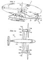
Figure 1 is a perspective view of a helicopter having a composite drive shaft with captured end adapters according to the present invention; -
Figure 2A is a plan view of a tilt rotor aircraft having a composite drive shaft with captured end adapters according to the present invention in an airplane mode; -
Figure 2B is a perspective view of another tilt rotor aircraft having a composite drive shaft with captured end adapters according to the present invention in a helicopter mode; -
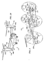
Figure 3 is a perspective view of a quad tilt rotor aircraft having a composite drive shaft with captured end adapters according to the present invention in the airplane mode; -
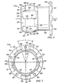
Figure 4 is an isometric view of the composite drive shaft with captured end adapters according to the present invention; -
Figure 5 is an isometric view of one of the end adapters of the composite drive shaft ofFigure 4 ; -
Figure 6 is a side view of the end adapter ofFigure 5 ; -
Figure 7 is a cross-sectional view of the end adapter ofFigure 6 taken at VII-VII. -
Figure 8 is a cross-sectional view of the adapter-tube interface of the composite drive shaft taken at VIII-VIII ofFigure 4 . - Referring to
Figure 1 in the drawings, ahelicopter 11 having a composite drive shaft with captured end adapters according to the present invention is illustrated.Helicopter 11 has afuselage 13 and amain rotor assembly 15, includingmain rotor blades 17 and amain rotor shaft 18.Helicopter 11 has atail rotor assembly 19, includingtail rotor blades 21 and atail rotor shaft 20.Main rotor blades 17 generally rotate about alongitudinal axis 16 ofmain rotor shaft 18.Tail rotor blades 21 generally rotate about alongitudinal axis 22 oftail rotor shaft 20.Main rotor blades 17 andtail rotor blades 21 are driven by a drive means 25 carried byfuselage 13. Torque is transmitted fromdrive means 25 totail rotor assembly 19 through at least one composite drive shaft having captured end adapters that is disposed within atail boom 27. - The present invention may also be utilized on other types of rotary wing aircraft. Referring now to
Figures 2A and2B in the drawings, atilt rotor aircraft 111 according to the present invention is illustrated. As is conventional with tilt rotor aircraft,rotor assemblies wings end portions wings Tilt rotor assemblies nacelles tilt rotor aircraft 111, as well as,rotor hubs forward ends tilt rotor assemblies - Tilt rotor assemblies 113a and 113b move or rotate relative to
wing members tilt rotor aircraft 111 flies like a conventional helicopter; and an airplane mode in which tilt rotor assemblies 113a and 113b are tilted forward, such thattilt rotor aircraft 111 flies like a conventional propeller driven aircraft. InFigure 2A ,tilt rotor aircraft 111 is depicted as a civilian-type tilt rotor aircraft, and is shown in the airplane mode; and inFigure 2B ,tilt rotor aircraft 111 is depicted as a military -type tilt rotor aircraft, and is shown in the helicopter mode. As shown inFigures 2A and2B ,wings fuselage 114.Tilt rotor aircraft 111 includes at least one composite drive shaft having captured end adapters that passes throughwings fuselage 114 fromtilt rotor assembly 113a totilt rotor assembly 113b. - Referring now to
Figure 3 in the drawings, a quadtilt rotor aircraft 211 having a composite drive shaft with captured end adapters according to the present invention is illustrated. As with the tilt rotor aircraft ofFigures 2A and2B ,tilt rotor assemblies wings Tilt rotor assemblies nacelles tilt rotor aircraft 211, as well as,rotor hubs tilt rotor assemblies - Tilt rotor assemblies 213a, 213b, 213c, and 213d move or rotate relative to
wing members tilt rotor aircraft 211 flies like a conventional helicopter; and an airplane mode in which tilt rotor assemblies 213a, 213b, 213c, and 213d are tilted forward, such that quadtilt rotor aircraft 211 flies like a conventional propeller driven aircraft. InFigure 3 , quadtilt rotor aircraft 111 is shown in the airplane mode. As shown inFigure 3 ,wings fuselage 214. Quadtilt rotor aircraft 211 includes at least one composite drive shaft having captured end adapters that passes throughwings fuselage 214 fromtilt rotor assembly 213a to tiltrotor assembly 213c, and/or at least one composite drive shaft having captured end adapters that passes throughwings fuselage 214 fromtilt rotor assembly 213b to tiltrotor assembly 213d. Quadtilt rotor aircraft 211 may also include at least one composite drive shaft having captured end adapters that passes throughfuselage 214 in the fore and aft direction connecting the shaft system inforward wings aft wings - It should be understood that the present invention may be used with any aircraft on which it would be desirable to have a composite drive shaft with captured end adapters according to the present invention, including unmanned aerial vehicles that are remotely piloted. In addition, it will be appreciated that the present invention may be used in non-torque applications, such as an aircraft refueling boom or a landing gear actuator shaft. The composite drive shaft with captured end adapters may also be in other industries beside the aircraft industry, such as the automotive industry and the manufacturing industry. Indeed, the present invention may be used in any application in which it is desirable to have a low-weight, high-strength, high-speed, and/or high-torque composite drive shaft.
- Referring now to
Figure 4 in the drawings, adrive shaft assembly 311 comprising a composite material portion, referred to herein as acomposite tube 313, and capturedend adapters End adapters composite tube 313 atend portions composite tube 313, respectively, during the process of manufacturingcomposite tube 313. In the preferred embodiment,composite tube 313 is a braided fiber and resin transfer molded component. Such components are typically more damage tolerant and have a higher ballistic survivability. The braided fiber may be either a two-dimensional or a three dimensional braided fiber. However, it should be understood thatcomposite tube 313 may also be manufactured by filament winding, fiber placement, or any other processes that are deemed appropriate. - Although
end adapters composite tube 313 may be manufactured such thatend adapters - Referring now to
Figures 5-7 in the drawings,end adapter 315a is illustrated prior to being captured during the process of manufacturingcomposite tube 313. It should be understood that any discussion or description herein ofend adapter 315a applies equally to endadapter 315b, and vice versa.End adapter 315a is preferably formed from a metallic material, such as aluminum, titanium, or steel, but may be formed from any other suitable rigid material. -
End adapter 315a preferably includes aninterface portion 319 that is configured to be coupled to the end adapter of a driving or driven shaft or component (not shown). As is shown,interface portion 319 includes a plurality of optional spaced apartengagement teeth 321 and fastener holes 323. It will be appreciated thatoptional engagement teeth 321 andfastener holes 323 are representative of any type of clamping or clasping means for couplingend adapter 315a to the driving or driven shaft or component.Interface portion 319 transitions into aneck portion 325.Neck portion 325 may be configured in a wide variety of cross-sectional shapes and sizes, depending upon the desired application. For example, as is shown,neck portion 325 has a reduced cross-sectional area. This allows clearance for and easy access to fasteners (not shown) that pass through fastener holes 323. It will be appreciated that in some applications,neck portion 325 may not be necessary.End adapter 315a terminatesopposite interface portion 319 with aninterior end 326. -
End adapter 315a includes an adapter-tube interface 327 that is configured to engagecomposite tube 313. In the preferred embodiment, adapter-tube interface 327 comprises a plurality oflugs 329 spaced around the periphery of adapter-tube interface 327.Lugs 329 protrude radially outward to engage the interior surface ofcomposite tube 313, as is shown inFigure 8 , betweenlugs 329 andcomposite laminate 351. Eachlug 329 includes alug face 331, opposing lug flanks 333, and opposing lug ends 335.Lugs 329 are separated by a generally longitudinal groove having a bottom that is referred to herein as alug base 337. - Lug faces 331 form circumferentially exterior top surfaces that engage the circumferentially interior surface of
composite tube 313, as shown inFigure 8 . Lug faces 331 may be smooth, flat, or curved. Opposing lug flanks 333 are preferably radially aligned longitudinal surfaces having filet radii. As will be explained in more detail below, the filet radii function to reduce stress concentration and provide a smooth transition for the fibers ofcomposite tube 313. Opposing lug flanks 333 function to transmit torque fromend adapter 315a tocomposite tube 313 and vice versa. The leadinglug flank 333 of onelug 329 and the trailinglug flank 333 of theadjacent lug 329 form an angle A. The number oflugs 329 and angle A are determined by the design requirements of the drive shaft, including the load and stress distributions for optimized drive shaft strength, and the method of mating the drive shaft with other components or shafts. It will be appreciated that lug flanks 333 may be angled with respect to anaxis 334 of the drive shaft, or may be crowned. In this manner, lead correction can be applied to lugs 329. Opposing lug ends 335 transition fromneck portion 325 at one end and frominterior end 326 at the opposing end, and taper toward each other with increasing radial distance. Opposing lug ends 335 function to support axial tensile and compressive loads and bending moments. It will be appreciated the taper of lug ends 335 may be steep, such as 90°, to carry additional axial forces and bending moments. Lug bases 337 may be flat, smooth, or curved. - Although
end adapter 315a is shown disposed partly withincomposite tube 313 and partly outside ofcomposite tube 313, it should be understood thatend adapter 315a may be disposed entirely withincomposite tube 313, and may include an internal interface portion. - In an alternate embodiment, lugs 329 are hollowed out, as is indicated by the dashed
line 339 inFigure 7 . This hollowing out of one or more oflugs 329 reduces the weight ofend adapter 315a. - In another alternate embodiment, at least one circumferential groove across lug faces 331 (not shown) and extending radially inward from lug faces 331 may be included to further facilitate bending moments. In such embodiments, it is preferred that the circumferential grooves extend radially inward to lug
base 337. - Referring now to
Figure 8 in the drawings,end adapter 315b interfaced withcomposite tube 313 is shown in a cross-sectional view taken at VIII-VIII ofFigure 4 . As is shown, lugs 329 ofend adapter 315b are captured by the layers ofcomposite laminate 351 that is part ofcomposite tube 313. As set forth above, in the preferred embodiment,composite laminate 351 is a braided composite. This capturing process is performed during the process of laying up and manufacturingcomposite tube 313. In the preferred embodiment, lugs 329 are entirely surrounded by braidedfibers 351. The layering ofcomposite laminate 351 down to lugbases 337 between lug flanks 333 provides a positive engagement betweencomposite tube 313 andend adapters Filets 353 at the intersection of lug flanks 333 and lugbases 337 aid in reducing stress concentrations incomposite laminate 351 and lugs 329.Filets 353 also provide a smooth transition fromlug bases 337 to lugflanks 333 to prevent a resin rich situation at the intersection. - The preferred process of manufacturing
drive shaft assembly 311 will now be described. First,end adapters composite tube 313, which comprises polymer or plastic fibers, is applied over the mandrel andend adapters end adapter 315a and the polymer or plastic fibers, so that the adhesive is disposed betweenend adapter 315b andcomposite tube 313. Next, one or more tools or molds configured to match the composite preform, includingend adapters composite tube 313, are clamped down over the entire assembly. Then, the assembly is heated, evacuated, injected with resin, and cured to formdrive shaft assembly 311. - As set forth above, in alternate embodiments,
composite tube 313 may be formed by other means, such as filament winding, filament placement, or any other type of composite manufacturing technique. In such instances, pre-impregnated fibers are applied over the mandrel andend adapter 315b by filament winding or filament placement processes. The assembly is then enclosed in vacuum bags and evacuated. Next, the resin is cured. Then, the vacuum bags and mandrel are removed. - Because no fasteners are required, no drilling of fastener holes is necessary, and no fasteners protrude outward. This reduces the possibility of interference with electrical lines, hydraulic lines, and other components when installed and operated on the aircraft. The only post-cure processing that is required is simple trimming of the exposed ends of
composite laminate 351. By manufacturingdrive shaft assembly 311 in this manner, misalignment ofend adapters - It will be appreciated that
end adapters drive shaft assembly 311 by simply burning offcomposite laminate 351, should any driveshaft assembly 311 either contain a manufacturing defect, or become damaged during use. This ability to recover andre-use end adapters - The composite drive shaft according to the present invention provides significant benefits and advantages, including: (1) the costs of manufacturing the shaft are lower; (2) the shaft is less susceptible to corrosion; (3) the shaft has greater strength; (4) the shaft is lighter; (5) because the end adapters do not clamp or bite into the composite material, the integrity of the composite material is maintained; (6) because bolts are not necessary, fewer parts are necessary; (7) because bolt holes are not drilled through the composite and end adapters, crack initiation and propagation is greatly reduced; (8) the shaft can be used in high speed and high torque applications; (9) post-cure cutting and machining of the composite tube are minimized; and (10) the end adapters can be recovered from damaged assemblies and re-used.
Claims (16)
- A drive shaft comprising:an elongated thermoset composite material portion (313) having opposing ends (317a, 317b); andat least one metallic end adapter (315a) disposed at one end of the composite material portion (313), the end adapter (315a) being captured in the composite material portion (313) during the process of manufacturing of the composite material portion (313) so as to form an integral shaft (311),the end adapter (315a) having a plurality of radially outwardly protruding lugs (329) on an outer surface thereof, said lugs (329) being captured in the composite material portion (313) to transmit torque from the end adapter (315a) to the composite material portion (313) and vice versa,
characterized in that each lug (329) comprisesa circumferentially exterior lug face (331);a lug flank (333) on each side of the lug face (331) for transmitting torque from the end adapter (315a) to the composite material portion (313) and vice versa;a lug base (337) between the lug flanks (333) of adjacent lugs (329); anda tapered lug end (335) on each longitudinal end of the lug (329) for r supporting axial tensile loads, axial compressive loads and bending moments. - The drive shaft according to claim 1, characterized in that the end adapter (315a) is hollow.
- The drive shaft according to claim 1, characterized in that the composite material portion (313) is formed from a braided fiber and resin transfer molded composite.
- The drive shaft according to claim 3, characterized in that the braided fiber is a two-dimensional braided fiber.
- The drive shaft according to claim 3, characterized in that the braided fiber is a three-dimensional braided fiber.
- The drive shaft according to claim 1, characterized in that the composite material portion is formed from a filament wound composite.
- The drive shaft according to claim 1, characterized in that an adhesive film is disposed between the end adapter (315a) and the composite material portion (313).
- The drive shaft according to claim 1, characterized in that the end adapter further comprises a neck portion (325) disposed between a component interface portion (319) and an adapter composite interface portion (327), the neck portion (325) having a reduced cross-sectional area.
- The drive shaft according to claim 1, characterized in that the end adapter further comprises at least one recessed circumferential groove around an adapter-composite interface portion, the circumferential groove separating the lugs into two rows of lugs, the circumferential groove being configured to increase the load bearing capacity of the drive shaft.
- The drive shaft according to claim 1, characterized in that the lug flanks (333) of adjacent lugs (329) are radially aligned.
- The drive shaft according to claim 1, characterized in that the lug flanks (339) are longitudinally angled from zero to any degree.
- The drive shaft according to claim 1, characterized in that the lug flanks (333) include a longitudinal crown.
- The drive shaft according to claim 1, characterized in that the lugs (329) are solid.
- The drive shaft according to claim 1, characterized in that the lugs (329) are hollowed out to reduce weight
- A method of manufacturing a drive shaft comprising the steps of:providing an elongated mandrel;providing two end adapters (315a, 315b), each end adapter (315a, 315b) comprising:a component interface portion (319) adapted for coupling to a driving or drive component;an adapter-composite interface portion (327); anda plurality of outwardly protruding lugs (329) disposed at the adapter-composite interface portion (327), each lug (329) comprisinga circumferentially exterior lug face (331),a lug flank (333) on each side of the lug face (331) for transmitting torque from the end adapter (315a) to the composite material portion (313) and vice versa,a lug base (337) between the lug flanks (333) of adjacent lugs (329); anda tapered lug end (335) on each longitudinal end of the lug (329) for supporting axial tensile loads, axial compressive loads, and bending moments,placing the end adapters (315a, 315b) over the mandrel,applying polymer or plastic fibers over the mandrel and end adapters (315a, 315b) to form a preform;providing a mold configured to fit over the preform;enclosing the preform with the mold;heating the assembly of mold and perform;vacuum the mold;injecting resin into the mold;curing the resin to form the drive shaft; removing the mold; andremoving the mandrel.
- The method according to claim 15, characterized by further comprising the step of:placing an adhesive film on the adapter-composite interface portion (327) of the end adapter (315a, 315b)before the step of applying the polymer or plastic fibers over the mandrel and end adapters (315a, 315b) to form the preform.
Applications Claiming Priority (3)
| Application Number | Priority Date | Filing Date | Title |
|---|---|---|---|
| US37430802P | 2002-04-19 | 2002-04-19 | |
| US374308P | 2002-04-19 | ||
| PCT/US2003/012423 WO2003089145A2 (en) | 2002-04-19 | 2003-04-18 | Composite drive shaft with captured end adapters |
Publications (3)
| Publication Number | Publication Date |
|---|---|
| EP1499554A2 EP1499554A2 (en) | 2005-01-26 |
| EP1499554A4 EP1499554A4 (en) | 2006-03-01 |
| EP1499554B1 true EP1499554B1 (en) | 2010-08-25 |
Family
ID=29251172
Family Applications (1)
| Application Number | Title | Priority Date | Filing Date |
|---|---|---|---|
| EP03719885A Expired - Lifetime EP1499554B1 (en) | 2002-04-19 | 2003-04-18 | Composite drive shaft with captured end adapters |
Country Status (7)
| Country | Link |
|---|---|
| US (1) | US7335108B2 (en) |
| EP (1) | EP1499554B1 (en) |
| AU (1) | AU2003223688A1 (en) |
| BR (1) | BR0309371A (en) |
| CA (1) | CA2481730C (en) |
| DE (2) | DE03719885T1 (en) |
| WO (1) | WO2003089145A2 (en) |
Cited By (1)
| Publication number | Priority date | Publication date | Assignee | Title |
|---|---|---|---|---|
| CN108472858A (en) * | 2015-12-31 | 2018-08-31 | 穆格公司 | Compound torque tube end connector attachment method |
Families Citing this family (30)
| Publication number | Priority date | Publication date | Assignee | Title |
|---|---|---|---|---|
| DE112006003997B4 (en) * | 2006-08-23 | 2016-10-06 | Gkn Driveline North America, Inc. | Constant rotation joint connector with direct torque transmission through a spur toothing |
| KR100831643B1 (en) | 2007-04-10 | 2008-05-22 | 류충오 | Connection joints and composite drive shaft assemblies with them |
| DE102008056017A1 (en) * | 2008-11-05 | 2010-05-06 | Rolls-Royce Deutschland Ltd & Co Kg | Method for producing an engine shaft |
| EP2602496A1 (en) * | 2011-12-05 | 2013-06-12 | Magna Steyr Fahrzeugtechnik AG & Co KG | Connection between two components and method for connecting two components |
| FR3001656B1 (en) * | 2013-02-04 | 2015-06-26 | Safran | IMPROVED MANUFACTURING METHOD OF A TRANSMISSION SHAFT, PREFERABLY FOR AN AIRCRAFT TURBOMACHINE ACCESSORY BOX SYSTEM |
| US9441374B2 (en) | 2014-04-08 | 2016-09-13 | Goodrich Corporation | Struts and methods utilizing a compression collar |
| US9726325B2 (en) | 2014-05-01 | 2017-08-08 | Goodrich Corporation | Composite tube assemblies and methods |
| US9568040B2 (en) | 2014-06-02 | 2017-02-14 | Goodrich Corporation | Struts and methods utilizing a locking collar nut |
| US20160137308A1 (en) * | 2014-11-17 | 2016-05-19 | Hamilton Sundstrand Corporation | Ram air turbine with composite shaft |
| EP3081822B1 (en) * | 2015-04-16 | 2019-08-28 | AIRBUS HELICOPTERS DEUTSCHLAND GmbH | Hybrid metal-composite drive shaft unit and method of manufacturing the same |
| US9909624B2 (en) | 2015-09-22 | 2018-03-06 | Rohr, Inc. | Composite driveshaft for a rotary system |
| US20170082137A1 (en) * | 2015-09-22 | 2017-03-23 | Rohr, Inc. | Driveshaft for a rotary system |
| US9937671B2 (en) | 2016-01-15 | 2018-04-10 | Moog Inc. | All-composite torque tube with metal eyelets |
| US10272991B2 (en) * | 2016-06-23 | 2019-04-30 | Goodrich Corporation | Metallic composite joint |
| US11255373B2 (en) | 2016-09-23 | 2022-02-22 | Textron Innovations Inc. | Active thermal management for fire-tolerant drive systems |
| US20180086444A1 (en) | 2016-09-23 | 2018-03-29 | Bell Helicopter Textron Inc. | Aircraft Drive System |
| US10677261B2 (en) * | 2017-04-13 | 2020-06-09 | General Electric Company | Turbine engine and containment assembly for use in a turbine engine |
| US10689106B2 (en) | 2017-07-06 | 2020-06-23 | Bell Helicopter Textron Inc. | Fixed outboard engine tiltrotor with leading edge drive system and angled rotation spindle configuration |
| EP3427921B1 (en) | 2017-07-14 | 2021-11-17 | Crompton Technology Group Limited | Composite ball screw |
| FR3075898B1 (en) * | 2017-12-22 | 2019-11-29 | Safran Transmission Systems | TRANSMISSION SHAFT FOR A TURBOMACHINE |
| US11156245B2 (en) * | 2018-01-08 | 2021-10-26 | Goodrich Corporation | Hybrid metallic/composite axial tension/compression lobe joint |
| US11519454B2 (en) | 2019-07-24 | 2022-12-06 | Goodrich Corporation | Hybrid metallic/composite tube design to transfer bending, axial, and flexural shear |
| US12140182B2 (en) | 2019-11-25 | 2024-11-12 | Textron Innovations Inc. | Layup of tail rotor drive shaft tubes |
| US11724813B2 (en) | 2021-05-24 | 2023-08-15 | General Electric Company | Midshaft rating for turbomachine engines |
| US12203377B2 (en) | 2021-05-24 | 2025-01-21 | General Electric Company | Midshaft rating for turbomachine engines |
| US12071978B2 (en) | 2021-05-24 | 2024-08-27 | General Electric Company | Midshaft rating for turbomachine engines |
| US11808214B2 (en) | 2021-05-24 | 2023-11-07 | General Electric Company | Midshaft rating for turbomachine engines |
| US20220373019A1 (en) * | 2021-05-24 | 2022-11-24 | General Electric Company | Midshaft rating for turbomachine engines |
| US11603801B2 (en) | 2021-05-24 | 2023-03-14 | General Electric Company | Midshaft rating for turbomachine engines |
| US12392307B2 (en) | 2023-03-24 | 2025-08-19 | General Electric Company | High-speed shaft rating for turbine engines |
Family Cites Families (11)
| Publication number | Priority date | Publication date | Assignee | Title |
|---|---|---|---|---|
| JPS54151677A (en) * | 1978-05-16 | 1979-11-29 | Toyo Boseki | Concentrator for polyvinylalcohol |
| US4561799A (en) * | 1982-02-08 | 1985-12-31 | Grumman Aerospace Corp. | Torque joint |
| EP0474441A3 (en) * | 1990-08-30 | 1993-06-16 | Sumitomo Chemical Company, Limited | Fiber-reinforced plastics drive shafts |
| US5342464A (en) | 1992-04-24 | 1994-08-30 | United Technologies Corporation | Bonding of thermoplastic composite structures to metal structures |
| US5304012A (en) * | 1992-07-01 | 1994-04-19 | Curtiss Wright Flight Systems Inc. | Drive shaft fitting or coupling |
| DE19524901A1 (en) * | 1995-07-08 | 1997-04-30 | Inst Kraftfahrwesen Rwth Aache | Force transmission device for use in vehicle construction |
| DE19524903A1 (en) * | 1995-07-08 | 1997-04-30 | Inst Kraftfahrwesen Rwth Aache | Force transmission device for use in vehicle construction |
| US6336986B1 (en) * | 1997-07-14 | 2002-01-08 | Korea Advanced Institute Science Technology | Method for producing hybrid driveshaft |
| DE19900449C2 (en) * | 1999-01-08 | 2003-01-23 | Daimler Chrysler Ag | drive shaft |
| JP3420754B2 (en) | 2000-10-10 | 2003-06-30 | 株式会社豊田自動織機 | Propeller shaft |
| US6932118B2 (en) * | 2002-09-24 | 2005-08-23 | The Boeing Company | Low chamfer angled torque tube end fitting metal |
-
2003
- 2003-04-18 WO PCT/US2003/012423 patent/WO2003089145A2/en not_active Ceased
- 2003-04-18 AU AU2003223688A patent/AU2003223688A1/en not_active Abandoned
- 2003-04-18 DE DE03719885T patent/DE03719885T1/en active Pending
- 2003-04-18 BR BR0309371-9A patent/BR0309371A/en not_active Application Discontinuation
- 2003-04-18 EP EP03719885A patent/EP1499554B1/en not_active Expired - Lifetime
- 2003-04-18 CA CA2481730A patent/CA2481730C/en not_active Expired - Lifetime
- 2003-04-18 DE DE60333912T patent/DE60333912D1/en not_active Expired - Lifetime
- 2003-04-18 US US10/511,658 patent/US7335108B2/en not_active Expired - Lifetime
Cited By (2)
| Publication number | Priority date | Publication date | Assignee | Title |
|---|---|---|---|---|
| CN108472858A (en) * | 2015-12-31 | 2018-08-31 | 穆格公司 | Compound torque tube end connector attachment method |
| CN108472858B (en) * | 2015-12-31 | 2020-09-25 | 穆格公司 | Composite torque tube end fitting attachment method |
Also Published As
| Publication number | Publication date |
|---|---|
| AU2003223688A1 (en) | 2003-11-03 |
| CA2481730C (en) | 2010-03-23 |
| US7335108B2 (en) | 2008-02-26 |
| EP1499554A2 (en) | 2005-01-26 |
| EP1499554A4 (en) | 2006-03-01 |
| CA2481730A1 (en) | 2003-10-30 |
| WO2003089145A2 (en) | 2003-10-30 |
| US20050239562A1 (en) | 2005-10-27 |
| AU2003223688A8 (en) | 2003-11-03 |
| WO2003089145A3 (en) | 2004-08-05 |
| DE03719885T1 (en) | 2005-06-23 |
| BR0309371A (en) | 2005-02-22 |
| DE60333912D1 (en) | 2010-10-07 |
Similar Documents
| Publication | Publication Date | Title |
|---|---|---|
| CA2481730C (en) | Composite drive shaft with captured end adapters | |
| US10294982B2 (en) | Systems, methods, and apparatus for supported shafts | |
| US10280969B2 (en) | Hybrid metal-composite drive shaft unit and method of manufacturing same | |
| CA2667469C (en) | Propeller blade retention | |
| KR101488013B1 (en) | An article comprising a composite structure having a mounting flange | |
| KR102064245B1 (en) | How to attach the composite torque tube end fitting | |
| EP2634091B1 (en) | Helicopter blade retention composite yoke | |
| EP3486503B1 (en) | Designs and methods of making of joints for composite components under dominant bending load | |
| CA2660845A1 (en) | Composite-steel hybrid mast for rotorcraft | |
| EP3477130B1 (en) | Composite tubular structure | |
| US11732746B2 (en) | Drive shaft with an integrated flange | |
| US20150275959A1 (en) | Systems, methods, and apparatus for internally supported shafts | |
| EP0749385B1 (en) | An expandable spar filler block device | |
| US11001369B2 (en) | Hybrid light weight rotorcraft hub trunnions | |
| US11718391B2 (en) | Rotary aircraft hybrid rotor mast |
Legal Events
| Date | Code | Title | Description |
|---|---|---|---|
| PUAI | Public reference made under article 153(3) epc to a published international application that has entered the european phase |
Free format text: ORIGINAL CODE: 0009012 |
|
| 17P | Request for examination filed |
Effective date: 20041029 |
|
| AK | Designated contracting states |
Kind code of ref document: A2 Designated state(s): AT BE BG CH CY CZ DE DK EE ES FI FR GB GR HU IE IT LI LU MC NL PT RO SE SI SK TR |
|
| AX | Request for extension of the european patent |
Extension state: AL LT LV MK |
|
| EL | Fr: translation of claims filed | ||
| DET | De: translation of patent claims | ||
| A4 | Supplementary search report drawn up and despatched |
Effective date: 20060118 |
|
| 17Q | First examination report despatched |
Effective date: 20060719 |
|
| GRAP | Despatch of communication of intention to grant a patent |
Free format text: ORIGINAL CODE: EPIDOSNIGR1 |
|
| GRAS | Grant fee paid |
Free format text: ORIGINAL CODE: EPIDOSNIGR3 |
|
| GRAA | (expected) grant |
Free format text: ORIGINAL CODE: 0009210 |
|
| AK | Designated contracting states |
Kind code of ref document: B1 Designated state(s): DE FR GB IT |
|
| REG | Reference to a national code |
Ref country code: GB Ref legal event code: FG4D |
|
| REF | Corresponds to: |
Ref document number: 60333912 Country of ref document: DE Date of ref document: 20101007 Kind code of ref document: P |
|
| PLBE | No opposition filed within time limit |
Free format text: ORIGINAL CODE: 0009261 |
|
| STAA | Information on the status of an ep patent application or granted ep patent |
Free format text: STATUS: NO OPPOSITION FILED WITHIN TIME LIMIT |
|
| 26N | No opposition filed |
Effective date: 20110526 |
|
| REG | Reference to a national code |
Ref country code: DE Ref legal event code: R097 Ref document number: 60333912 Country of ref document: DE Effective date: 20110526 |
|
| REG | Reference to a national code |
Ref country code: FR Ref legal event code: PLFP Year of fee payment: 14 |
|
| REG | Reference to a national code |
Ref country code: FR Ref legal event code: PLFP Year of fee payment: 15 |
|
| REG | Reference to a national code |
Ref country code: FR Ref legal event code: PLFP Year of fee payment: 16 |
|
| PGFP | Annual fee paid to national office [announced via postgrant information from national office to epo] |
Ref country code: IT Payment date: 20220421 Year of fee payment: 20 Ref country code: GB Payment date: 20220427 Year of fee payment: 20 Ref country code: FR Payment date: 20220425 Year of fee payment: 20 Ref country code: DE Payment date: 20220427 Year of fee payment: 20 |
|
| REG | Reference to a national code |
Ref country code: DE Ref legal event code: R071 Ref document number: 60333912 Country of ref document: DE |
|
| REG | Reference to a national code |
Ref country code: GB Ref legal event code: PE20 Expiry date: 20230417 |
|
| PG25 | Lapsed in a contracting state [announced via postgrant information from national office to epo] |
Ref country code: GB Free format text: LAPSE BECAUSE OF EXPIRATION OF PROTECTION Effective date: 20230417 |