EP1499201B1 - Apparatus and method for making confectionery on a stick - Google Patents
Apparatus and method for making confectionery on a stick Download PDFInfo
- Publication number
- EP1499201B1 EP1499201B1 EP03722757A EP03722757A EP1499201B1 EP 1499201 B1 EP1499201 B1 EP 1499201B1 EP 03722757 A EP03722757 A EP 03722757A EP 03722757 A EP03722757 A EP 03722757A EP 1499201 B1 EP1499201 B1 EP 1499201B1
- Authority
- EP
- European Patent Office
- Prior art keywords
- stick
- receiving means
- mould
- condition
- forming surface
- Prior art date
- Legal status (The legal status is an assumption and is not a legal conclusion. Google has not performed a legal analysis and makes no representation as to the accuracy of the status listed.)
- Expired - Lifetime
Links
- 235000009508 confectionery Nutrition 0.000 title claims description 9
- 238000000034 method Methods 0.000 title claims description 5
- 235000011475 lollipops Nutrition 0.000 claims description 44
- 238000004519 manufacturing process Methods 0.000 claims description 13
- 230000014759 maintenance of location Effects 0.000 claims description 3
- 238000011065 in-situ storage Methods 0.000 claims description 2
- 230000000750 progressive effect Effects 0.000 claims description 2
- 238000000465 moulding Methods 0.000 description 2
- 230000000712 assembly Effects 0.000 description 1
- 238000000429 assembly Methods 0.000 description 1
- 238000001816 cooling Methods 0.000 description 1
Images



Classifications
-
- A—HUMAN NECESSITIES
- A23—FOODS OR FOODSTUFFS; TREATMENT THEREOF, NOT COVERED BY OTHER CLASSES
- A23G—COCOA; COCOA PRODUCTS, e.g. CHOCOLATE; SUBSTITUTES FOR COCOA OR COCOA PRODUCTS; CONFECTIONERY; CHEWING GUM; ICE-CREAM; PREPARATION THEREOF
- A23G3/00—Sweetmeats; Confectionery; Marzipan; Coated or filled products
- A23G3/34—Sweetmeats, confectionery or marzipan; Processes for the preparation thereof
- A23G3/50—Sweetmeats, confectionery or marzipan; Processes for the preparation thereof characterised by shape, structure or physical form, e.g. products with supported structure
- A23G3/56—Products with edible or inedible supports, e.g. lollipops
- A23G3/563—Products with edible or inedible supports, e.g. lollipops products with an inedible support, e.g. a stick
-
- A—HUMAN NECESSITIES
- A23—FOODS OR FOODSTUFFS; TREATMENT THEREOF, NOT COVERED BY OTHER CLASSES
- A23G—COCOA; COCOA PRODUCTS, e.g. CHOCOLATE; SUBSTITUTES FOR COCOA OR COCOA PRODUCTS; CONFECTIONERY; CHEWING GUM; ICE-CREAM; PREPARATION THEREOF
- A23G7/00—Other apparatus or process specially adapted for the chocolate or confectionery industry
- A23G7/0031—Apparatus for manipulating sticks
-
- A—HUMAN NECESSITIES
- A23—FOODS OR FOODSTUFFS; TREATMENT THEREOF, NOT COVERED BY OTHER CLASSES
- A23G—COCOA; COCOA PRODUCTS, e.g. CHOCOLATE; SUBSTITUTES FOR COCOA OR COCOA PRODUCTS; CONFECTIONERY; CHEWING GUM; ICE-CREAM; PREPARATION THEREOF
- A23G7/00—Other apparatus or process specially adapted for the chocolate or confectionery industry
- A23G7/0043—Other processes specially adapted for the chocolate or confectionery industry
- A23G7/005—General processes
- A23G7/0081—Processes for manipulating sticks
-
- A—HUMAN NECESSITIES
- A23—FOODS OR FOODSTUFFS; TREATMENT THEREOF, NOT COVERED BY OTHER CLASSES
- A23G—COCOA; COCOA PRODUCTS, e.g. CHOCOLATE; SUBSTITUTES FOR COCOA OR COCOA PRODUCTS; CONFECTIONERY; CHEWING GUM; ICE-CREAM; PREPARATION THEREOF
- A23G9/00—Frozen sweets, e.g. ice confectionery, ice-cream; Mixtures therefor
- A23G9/04—Production of frozen sweets, e.g. ice-cream
- A23G9/22—Details, component parts or accessories of apparatus insofar as not peculiar to a single one of the preceding groups
- A23G9/26—Details, component parts or accessories of apparatus insofar as not peculiar to a single one of the preceding groups for producing frozen sweets on sticks
- A23G9/265—Details, component parts or accessories of apparatus insofar as not peculiar to a single one of the preceding groups for producing frozen sweets on sticks for manipulating the sticks
Definitions
- the present invention reflates to apparatus and a method for the manufacture of confectionery, and in particular, but not exclusively, to the manufacture of lollipops.
- a known apparatus for manufacture of lollipops is disclosed in DE 4128905 in which lollipop sticks are pushed downwardly into a lollipop mould assembly.
- a lollipop mould assembly which comprises stick receiving means and a mould forming surface of a mould, the stick receiving means being pivotably mounted relative to the mould forming surface for pivotal movement of the stick receiving means rotative to the mould forming surface from a first condition to a second condition, the arrangement being such that, in use, a lollipop stick is received by the stick receiving means in the first condition, in which a distal free end of the stick is outside of a region which is defined by the mould forming surface, and relative pivotal movement is then brought about to cause the stick receiving means to adopt the second condition in which the distal free end of the stick extends into the region defined by the mould forming surface and in which second condition confectionery material is provided into the mould and around at least part of the lollipop stick.
- the extent of relative pivotal movement from the first condition to the second condition is substantially ninety degrees.
- the stick receiving means can receive the stick in a substantially vertical condition, and the stick receiving means then moves through ninety degrees to a substantially horizontal condition. This is particularly advantageous when lollipops are produced which require the strick to lie horizontally on the mould during the provision of the confectionery.
- the assembly preferably comprises actuation means operative to cause controller relative pivotal movement of the stick receiving means in response to a progressive movement of the mould assembly along a circuit of a lollipop manufacturing apparatus.
- the actuation means preferably comprises a cam follower of which the movement is determined by the configuration of a cam track.
- the assembly desirably comprises location means which is such that when the stick is in situ in the location means the stick is in the second condition.
- the stick receiving means may be provided by a bore.
- Stick retention means may be provided which comprises a spring loaded feature which is biased inwardly of the bore.
- Lollipop manufacturing apparatus comprising lollipop stick receiving means, a mould comprising a mould forming surface and a lollipop manufacturing circuit, the stick receiving means being pivotably mounted relative to the mould forming surface for pivotal movement of the stick receiving means relative to the mould forming surface from a first condition to a second condition, and stick receiving means being adapted to receive a lollipop stick, the arrangement of the apparatus being such that, in use, the position of the stick receiving means relative to the mould forming surface is determined by the position of the stick receiving means along the circuit, wherein the lollipop stick is received by the stick receiving means in the first condition in which a distal free end of the stick is outside of a region which is defined by the mould forming surface, and relative pivotal movement is then brought about to cause the stick receiving means to adopt the second condition in which the distal free end of the stick extends into the region defined by the mould forming surface.
- a process of manufacturing lollipops comprising locating a lollipop stick in stick receiving means of a lollipop mould assembly, the stick receiving means being in a first condition in which a distal free end of the stick is outside of a region which is defined by a mould forming surface of a mould, the stick receiving means being pivotably mounted relative to the mould forming surface, causing pivotal movement of the stick receiving means relative to a mould forming surface of a mould of the assembly so that the stick receiving means adopts a second condition in which the distal free end of the stick extends into the region defined by the mould forming surface and in which second condition confectionery material is provided into the mould and around at least part of the lollipop stick.
- a lollipop mould assembly 1 comprising stick receiving means 2 and a mould forming surface 3, the stick receiving means is pivotally mounted relative to the mould forming surface 3 by way of a pivot 5.
- the stick receiving means comprises a block 6 of oblong-rectangular transverse cross-section which is provided with an open bore 7 which extends through the block, and is substantially parallel to the longitudinal axis thereof.
- Frusto-conical openings 9 and 10 are provided at each end of the block 6 and are concentric with respect to the bore 7.
- Two spring-loaded detent features 12 and 13 are provided internally of the bore 7 which are biased to extend into said bore
- the pivot 5 is attached to a side wall 14 which is perpendicular to the axis of rotation of the pivot.
- the side wall 14 is integral with a portion 15 which defines the mould forming surface 3, a de-moulding conduit 17 and a location channel 18, the de-moulding conduit 17 being located centrally of the mould forming surface 3 and being open at each distal end thereof.
- the mould assembly 1 operates as follows.
- the mould assembly 1 is connected to a circuit 34 which leads the assembly through the various stages of a lollipop manufacturing process.
- the mould assembly 1 is provided with an actuation arm 33 which at one end is rigidly attached to the block 6 and at the other is provided with a cam follower 36 which engages with a cam track 35.
- a conduit 29 guides sticks 4 into a stick feeder assembly 28.
- a spring-loaded detent feature 27 bears on the stick in the feeder assembly 28.
- the feeder assembly 28 is arranged for translational movement so that the feeder assembly follows the mould assembly whilst remaining in register with the bore 7 of the block 6 as the assembly 1 moves forward.
- a stick 4 is urged from the feeder assembly 28 into the bore 7.
- the detent feature 27 ensures that only one stick at a time is issued towards the bore 7. Once a stick has been deposited into the bore 7 after having been urged past the detent 27, the feeder assembly 28 is translated in the reverse direction to the starting position ready to issue another stick.
- an angled vibrating plate 19 urges the stick 4 downwardly to negotiate the detent feature 12, but the plate 19 is deliberately arranged not to be sufficient to negotiate the detent feature 13.
- the stick 4 is effectively held against the wall of the bore 7 by the detent feature 12 and is supported by detent feature 13.
- the cam track 35 is configured at 37 to pivot the actuating arm 33 (and hence the block 6) through ninety degrees.
- Figure 4 shows the block 6 in an intermediate orientation between the initial vertical condition and the eventual horizontal condition.
- the block 6 and hence the stick 4 has been pivoted through ninety degrees and is in a horizontal condition.
- the stick 4 rests on the location channel 18 and the distal free end 4 of the stick extends into a region which is defined by the mould forming surface 3.
- Confectionery material 21 is deposited into that region from a depositer 22.
- the mould assembly 1 is then driven forwards along the circuit 34 through a cooling tunnel (not shown) turning through one hundred and eighty degrees at 40 such that the mould assembly is in an inverted condition as shown in Figure 6 .
- an ejection pin 25 forces the newly formed lollipop though the bore 7 and in so doing overcoming the frictional retention force which has hitherto held the stick in position in the bore 7.
- the falling lollipop is grabbed by two actuated jaws 26 for further processing.
- cam track 35 is configured to ensure that the block 6 remains in the vertical condition to receiving another stick ready for the next cycle.
- the path of the cam track 35 may be configured to retain the stick of the lollipop at any convenient orientation or angle either for random ejection or regimented transportation for further processing, eg wrapping.
- an alternative embodiment may comprise mechanical ejection means, for example an actuated pin.
Landscapes
- Life Sciences & Earth Sciences (AREA)
- Chemical & Material Sciences (AREA)
- Engineering & Computer Science (AREA)
- Food Science & Technology (AREA)
- Polymers & Plastics (AREA)
- Confectionery (AREA)
Description
- The present invention reflates to apparatus and a method for the manufacture of confectionery, and in particular, but not exclusively, to the manufacture of lollipops.
- A known apparatus for manufacture of lollipops is disclosed in
DE 4128905 in which lollipop sticks are pushed downwardly into a lollipop mould assembly. - According to a first aspect of the invention there is provided a lollipop mould assembly which comprises stick receiving means and a mould forming surface of a mould, the stick receiving means being pivotably mounted relative to the mould forming surface for pivotal movement of the stick receiving means rotative to the mould forming surface from a first condition to a second condition, the arrangement being such that, in use, a lollipop stick is received by the stick receiving means in the first condition, in which a distal free end of the stick is outside of a region which is defined by the mould forming surface, and relative pivotal movement is then brought about to cause the stick receiving means to adopt the second condition in which the distal free end of the stick extends into the region defined by the mould forming surface and in which second condition confectionery material is provided into the mould and around at least part of the lollipop stick.
- Preferably, the extent of relative pivotal movement from the first condition to the second condition is substantially ninety degrees.
- In a preferred embodiment the stick receiving means can receive the stick in a substantially vertical condition, and the stick receiving means then moves through ninety degrees to a substantially horizontal condition. This is particularly advantageous when lollipops are produced which require the strick to lie horizontally on the mould during the provision of the confectionery.
- The assembly preferably comprises actuation means operative to cause controller relative pivotal movement of the stick receiving means in response to a progressive movement of the mould assembly along a circuit of a lollipop manufacturing apparatus.
- The actuation means preferably comprises a cam follower of which the movement is determined by the configuration of a cam track.
- The assembly desirably comprises location means which is such that when the stick is in situ in the location means the stick is in the second condition.
- The stick receiving means may be provided by a bore. Stick retention means may be provided which comprises a spring loaded feature which is biased inwardly of the bore.
- According to a second aspect of the invention there is provided Lollipop manufacturing apparatus comprising lollipop stick receiving means, a mould comprising a mould forming surface and a lollipop manufacturing circuit, the stick receiving means being pivotably mounted relative to the mould forming surface for pivotal movement of the stick receiving means relative to the mould forming surface from a first condition to a second condition, and stick receiving means being adapted to receive a lollipop stick, the arrangement of the apparatus being such that, in use, the position of the stick receiving means relative to the mould forming surface is determined by the position of the stick receiving means along the circuit, wherein the lollipop stick is received by the stick receiving means in the first condition in which a distal free end of the stick is outside of a region which is defined by the mould forming surface, and relative pivotal movement is then brought about to cause the stick receiving means to adopt the second condition in which the distal free end of the stick extends into the region defined by the mould forming surface.
- According to a third aspect of the invention there is provided a process of manufacturing lollipops comprising locating a lollipop stick in stick receiving means of a lollipop mould assembly, the stick receiving means being in a first condition in which a distal free end of the stick is outside of a region which is defined by a mould forming surface of a mould, the stick receiving means being pivotably mounted relative to the mould forming surface, causing pivotal movement of the stick receiving means relative to a mould forming surface of a mould of the assembly so that the stick receiving means adopts a second condition in which the distal free end of the stick extends into the region defined by the mould forming surface and in which second condition confectionery material is provided into the mould and around at least part of the lollipop stick.
- One embodiment of the invention will now be described, by way of example only, with reference to the accompanying drawings in which:
-
Figure 1 is a plan view of a mould assembly in a first condition, -
Figure 2 is a cross-sectional side elevation of the mould assembly shown inFigure 1 on section A-A in which a lollipop stick is being fed into the stick receiving means, -
Figure 3 is a snapshot subsequent toFigure 2 in which a lollipop stick is being urged into the stick receiving means, -
Figure 4 is a snapshot subsequent toFigure 3 in which the stick receiving means is pivoting towards the mould forming surface, -
Figure 5 is a snapshot subsequent toFigure 4 in which the stick receiving means is in a second condition and confectionery material is deposited into the region defined by the mould forming surface, -
Figure 6 is a snapshot subsequent toFigure 5 in which the mould assembly and the formed lollipop is inverted, -
Figure 7 is a snapshot subsequent toFigure 6 in which the stick receiving means which holds the lollipop captive is pivoted away from the mould forming surface, -
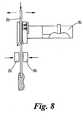
Figure 8 is a snapshot subsequent toFigure 7 on which the formed lollipop is released from the mould assembly, and -
Figure 9 is a schematic representation of a lollipop manufacture circuit around which the lollipop mould assembly ofFigures 1 to 8 is guided. - With reference to
Figure 1 there is shown alollipop mould assembly 1 comprisingstick receiving means 2 and amould forming surface 3, the stick receiving means is pivotally mounted relative to themould forming surface 3 by way of apivot 5. - The stick receiving means comprises a
block 6 of oblong-rectangular transverse cross-section which is provided with anopen bore 7 which extends through the block, and is substantially parallel to the longitudinal axis thereof. - Frusto-
conical openings block 6 and are concentric with respect to thebore 7. - Two spring-loaded
detent features bore 7 which are biased to extend into said bore - The
pivot 5 is attached to aside wall 14 which is perpendicular to the axis of rotation of the pivot. - The
side wall 14 is integral with aportion 15 which defines themould forming surface 3, ade-moulding conduit 17 and alocation channel 18, the de-mouldingconduit 17 being located centrally of themould forming surface 3 and being open at each distal end thereof. - In use the
mould assembly 1 operates as follows. Themould assembly 1 is connected to acircuit 34 which leads the assembly through the various stages of a lollipop manufacturing process. Themould assembly 1 is provided with anactuation arm 33 which at one end is rigidly attached to theblock 6 and at the other is provided with acam follower 36 which engages with acam track 35. - With reference to
Figure 2 aconduit 29 guides sticks 4 into astick feeder assembly 28. A spring-loaded detent feature 27 bears on the stick in thefeeder assembly 28. Thefeeder assembly 28 is arranged for translational movement so that the feeder assembly follows the mould assembly whilst remaining in register with thebore 7 of theblock 6 as theassembly 1 moves forward. - A
stick 4 is urged from thefeeder assembly 28 into thebore 7. Thedetent feature 27 ensures that only one stick at a time is issued towards thebore 7. Once a stick has been deposited into thebore 7 after having been urged past the detent 27, thefeeder assembly 28 is translated in the reverse direction to the starting position ready to issue another stick. - As shown in
Figure 3 , an angledvibrating plate 19 urges thestick 4 downwardly to negotiate thedetent feature 12, but theplate 19 is deliberately arranged not to be sufficient to negotiate thedetent feature 13. Thus thestick 4 is effectively held against the wall of thebore 7 by thedetent feature 12 and is supported bydetent feature 13. - As the
mould assembly 1 progresses along thecircuit 34, thecam track 35 is configured at 37 to pivot the actuating arm 33 (and hence the block 6) through ninety degrees.Figure 4 shows theblock 6 in an intermediate orientation between the initial vertical condition and the eventual horizontal condition. - With reference to
Figure 5 , theblock 6 and hence thestick 4 has been pivoted through ninety degrees and is in a horizontal condition. In such a condition thestick 4 rests on thelocation channel 18 and the distalfree end 4 of the stick extends into a region which is defined by themould forming surface 3.Confectionery material 21 is deposited into that region from adepositer 22. - The
mould assembly 1 is then driven forwards along thecircuit 34 through a cooling tunnel (not shown) turning through one hundred and eighty degrees at 40 such that the mould assembly is in an inverted condition as shown inFigure 6 . - As the assembly reaches that part of the
circuit 34 which is associated withportion 41 of thecam track 35 theblock 6 is caused to progressively pivot from a horizontal condition to a vertical condition. During such movement compressedair 30 is urged through theconduit 17 so as to assist in the demoulding process. - With reference to
Figure 8 anejection pin 25 forces the newly formed lollipop though thebore 7 and in so doing overcoming the frictional retention force which has hitherto held the stick in position in thebore 7. - The falling lollipop is grabbed by two actuated
jaws 26 for further processing. - After removal of the lollipop from the
assembly 1 thecam track 35 is configured to ensure that theblock 6 remains in the vertical condition to receiving another stick ready for the next cycle. - It will be appreciated that a plurality of juxtaposed
mould assemblies 1 could be provided to form what may be formed a bar. - The path of the
cam track 35 may be configured to retain the stick of the lollipop at any convenient orientation or angle either for random ejection or regimented transportation for further processing, eg wrapping. - It will be appreciated that although air ejection has been described, an alternative embodiment may comprise mechanical ejection means, for example an actuated pin.
Claims (9)
- A lollipop mould assembly which comprises stick receiving means (6) and a mould forming surface (3) of a mould (15), the stick receiving means being pivotably mounted relative to the mould forming surface for pivotal movement of the stick receiving means relative to the mould forming surface from a first condition to a second condition, the arrangement being such that, in use, a lollipop stick (4) is received by the stick receiving means in the first condition, in which a distal free end of the stick is outside of a region which is defined by the mould forming surface, and relative pivotal movement is then brought about to cause the stick receiving means to adopt the second condition in which the distal free end of the stick extends into the region defined by the mould forming surface and in which second condition confectionery material is provided into the mould and around at least part of the lollipop stick.
- An assembly as claimed in claim 1 in which the extent of relative pivotal movement from the first condition to the second condition is substantially ninety degrees.
- An assembly as claimed in claim 1 or claim 2 which comprises actuation means (33) operative to cause controlled relative pivotal movement of the stick receiving means in response to a progressive movement of the mould assembly along a circuit (34) of a lollipop manufacturing apparatus.
- An assembly as claimed in claim 3 in which the actuation means comprises a cam follower (33) of which the movement is determined by the configuration of a cam track (35).
- An assembly as claimed in any preceding claim which comprises location means (18) which is such that when the stick (4) is in situ in the location means the stick is in the second condition.
- An assembly as claimed in any preceding claim in which the receiving means (6) is provided by a bore (7).
- An assembly as claimed in claim 6 in which stick retention means (12, 13) is provided which comprises a spring loaded feature which is biased inwardly of the bore (7).
- Lollipop manufacturing apparatus comprising lollipop stick receiving means (6), a mould (15) comprising a mould forming surface (3) and a lollipop manufacturing circuit (34), the stick receiving means being pivotably mounted relative to the mould forming surface for pivotal movement of the stick receiving means relative to the mould forming surface from a first condition to a second condition, and stick receiving means being adapted to receive a lollipop stick (4), the arrangement of the apparatus being such that, in use, the position of the stick receiving means relative to the mould forming surface is determined by the position of the stick receiving means along the circuit, wherein the lollipop stick is received by the stick receiving means in the first condition in which a distal free end or the stick is outside of a region which is defined by the mould forming surface, and relative pivotal movement is then brought about to cause the stick receiving means to adopt the second condition in which the distal free end of the stick extends into the region defined by the mould forming surface.
- A process of manufacturing lollipops comprising locating a lollipop stick (4) in stick receiving means (6) of a lollipop mould assembly, the stick receiving means being in a first condition in which a distal free end of the suck is outside of a region which is defined by a mould forming surface of a mould, the stick receiving means being pivotally mounted relative to the mould forming surface, causing pivotal movement of the stick receiving means relative to a mould forming surface (3) of a mould (15) of the assembly so that the stick receiving means adopts a second condition in which the distal free end of the stick extends into the region defined by the mould forming surface and in which second condition confectionery material is provided into the mould and around at least part of the lollipop stick.
Applications Claiming Priority (3)
| Application Number | Priority Date | Filing Date | Title |
|---|---|---|---|
| GB0210093A GB2388007B (en) | 2002-05-02 | 2002-05-02 | Confectionery manufacture apparatus and method |
| GB0210093 | 2002-05-02 | ||
| PCT/GB2003/001680 WO2003092401A1 (en) | 2002-05-02 | 2003-04-17 | Apparatus and method for making confectionery on a stick |
Publications (2)
| Publication Number | Publication Date |
|---|---|
| EP1499201A1 EP1499201A1 (en) | 2005-01-26 |
| EP1499201B1 true EP1499201B1 (en) | 2012-11-28 |
Family
ID=9935970
Family Applications (1)
| Application Number | Title | Priority Date | Filing Date |
|---|---|---|---|
| EP03722757A Expired - Lifetime EP1499201B1 (en) | 2002-05-02 | 2003-04-17 | Apparatus and method for making confectionery on a stick |
Country Status (7)
| Country | Link |
|---|---|
| US (1) | US7223430B2 (en) |
| EP (1) | EP1499201B1 (en) |
| AU (1) | AU2003229920A1 (en) |
| CA (1) | CA2483540C (en) |
| ES (1) | ES2400238T3 (en) |
| GB (1) | GB2388007B (en) |
| WO (1) | WO2003092401A1 (en) |
Families Citing this family (5)
| Publication number | Priority date | Publication date | Assignee | Title |
|---|---|---|---|---|
| DE10340429A1 (en) | 2003-09-02 | 2005-04-07 | GESELLSCHAFT FüR BIOTECHNOLOGISCHE FORSCHUNG MBH (GBF) | Hydrophobic object with a pattern of hydrophilic areas, its production and use |
| NL1027556C2 (en) * | 2004-11-19 | 2006-05-22 | C F S Weert B V | Lolly machine. |
| NL1027735C2 (en) * | 2004-12-14 | 2006-06-16 | Cfs Weert Bv | Cooling machine for lollipops and the like. |
| US7955066B2 (en) * | 2008-01-07 | 2011-06-07 | Zensho Co., Ltd. | Ice-candy forming container |
| BR112016000831B1 (en) * | 2013-07-16 | 2021-10-05 | Gea Food Solutions Weert B.V. | METHOD FOR PRODUCING A LOPPY WITH A LOPPY HEAD AND TRAINING DEVICE WITH A TRAINING APPARATUS |
Family Cites Families (10)
| Publication number | Priority date | Publication date | Assignee | Title |
|---|---|---|---|---|
| GB674390A (en) * | 1949-04-08 | 1952-06-25 | Ralph Frederick Anderson | Improvements in stick dispensing machines |
| US3262403A (en) * | 1963-07-29 | 1966-07-26 | Lawrence H Teel | Forming device |
| US3730661A (en) * | 1970-10-26 | 1973-05-01 | John Lewis Inc | Stick inserter |
| DK149731C (en) * | 1975-06-25 | 1989-01-16 | Stormax Aps | DEVICE FOR INSERTING PINS IN ICE CREAM BODIES |
| GB9019107D0 (en) * | 1990-09-01 | 1990-10-17 | Apv Corp Ltd | Improvements in or relating to methods of and apparatus for the manufacture of confectionery |
| JP3336391B2 (en) * | 1993-07-27 | 2002-10-21 | 相吉産業株式会社 | Stick insertion device for frozen confectionery |
| DK61896A (en) * | 1996-05-31 | 1997-12-01 | Tetra Laval Food Hoyer A S | Grab and support element for ice stick products |
| IT1285766B1 (en) * | 1996-07-19 | 1998-06-18 | Catta 27 S R L | ARTICULATED, SELF-ALIGNING GRIPPER, PARTICULARLY SUITABLE FOR HANDLING ICE CREAM WITH A STICK |
| ES2186838T3 (en) * | 1997-06-12 | 2003-05-16 | Nestle Sa | WRAPPED PRODUCT FILLING A CONTAINER WITH STICK AND METHOD FOR PREPARATION. |
| JP3689561B2 (en) * | 1998-06-09 | 2005-08-31 | 株式会社イズミフードマシナリ | Stick insertion device for frozen desserts |
-
2002
- 2002-05-02 GB GB0210093A patent/GB2388007B/en not_active Expired - Fee Related
-
2003
- 2003-04-17 WO PCT/GB2003/001680 patent/WO2003092401A1/en not_active Ceased
- 2003-04-17 CA CA2483540A patent/CA2483540C/en not_active Expired - Fee Related
- 2003-04-17 AU AU2003229920A patent/AU2003229920A1/en not_active Abandoned
- 2003-04-17 ES ES03722757T patent/ES2400238T3/en not_active Expired - Lifetime
- 2003-04-17 US US10/513,248 patent/US7223430B2/en not_active Expired - Fee Related
- 2003-04-17 EP EP03722757A patent/EP1499201B1/en not_active Expired - Lifetime
Also Published As
| Publication number | Publication date |
|---|---|
| GB2388007B (en) | 2005-06-15 |
| CA2483540C (en) | 2012-08-07 |
| WO2003092401A1 (en) | 2003-11-13 |
| US7223430B2 (en) | 2007-05-29 |
| CA2483540A1 (en) | 2003-11-13 |
| ES2400238T3 (en) | 2013-04-08 |
| GB2388007A (en) | 2003-11-05 |
| EP1499201A1 (en) | 2005-01-26 |
| GB0210093D0 (en) | 2002-06-12 |
| US20050202124A1 (en) | 2005-09-15 |
| AU2003229920A1 (en) | 2003-11-17 |
Similar Documents
| Publication | Publication Date | Title |
|---|---|---|
| US3648625A (en) | Automatic pickup and enrobing apparatus for stick-type novelties | |
| NO137931B (en) | DEVICE FOR REMOVAL AND TRANSFER OF FORMBL} STE HOLE BODIES | |
| CA2483540C (en) | Apparatus and method for making confectionery on a stick | |
| US20210252740A1 (en) | Method and System for Demolding a Flexible Mold of Dried Wet-Cast Concrete Products | |
| EP1326488A2 (en) | Automatic feeder for strip-supported contacts | |
| CN111438334B (en) | Sand shakeout method and sand shakeout device | |
| JP5438913B2 (en) | PROJECTION PIN EXTRACTION DEVICE AND PROJECTION PIN OPERATING UNIT | |
| RU2280998C2 (en) | Method for production of lollipops | |
| US5620721A (en) | Assembly for preparing molded articles | |
| CN114043667B (en) | Mounting clamp for automobile door handle | |
| CN115972495B (en) | Processing equipment, processing systems and processing methods for sign hangers | |
| CN212446147U (en) | Full-automatic sprue separating and stripping machine for piezoelectric ignition device plastic body of lighter | |
| US4138785A (en) | Machine for clinching a multiple lead component | |
| KR100349053B1 (en) | Multistage metal-forming machine tool | |
| CN114952218A (en) | Nozzle assembling equipment | |
| CN105324036A (en) | Method and apparatus for forming flat lollipop | |
| JP2502040Y2 (en) | Indentation prevention device for heading machine | |
| CN111775418B (en) | Full-automatic pouring gate separating and stripping machine for plastic body of piezoelectric ignition device of lighter | |
| JPH02280870A (en) | Apparatus for painting elongate-rod-shaped body such as chopsticks | |
| JPS6262722A (en) | Releasing and removing of resin molded part and device thereof | |
| JP7023548B2 (en) | Ice confectionery manufacturing equipment, opening and closing mechanism | |
| CN213166688U (en) | Full-automatic injection molding equipment | |
| CN115213283A (en) | Automatic punching and assembling system for lengthened junction box | |
| JPH0773772B2 (en) | Work discharge device in press machine | |
| CA3072900A1 (en) | Method and system for demolding a flexible mold of dried wet-cast concrete products |
Legal Events
| Date | Code | Title | Description |
|---|---|---|---|
| PUAI | Public reference made under article 153(3) epc to a published international application that has entered the european phase |
Free format text: ORIGINAL CODE: 0009012 |
|
| 17P | Request for examination filed |
Effective date: 20041122 |
|
| AK | Designated contracting states |
Kind code of ref document: A1 Designated state(s): AT BE BG CH CY CZ DE DK EE ES FI FR GB GR HU IE IT LI LU MC NL PT RO SE SI SK TR |
|
| AX | Request for extension of the european patent |
Extension state: AL LT LV MK |
|
| DAX | Request for extension of the european patent (deleted) | ||
| 17Q | First examination report despatched |
Effective date: 20071105 |
|
| RAP1 | Party data changed (applicant data changed or rights of an application transferred) |
Owner name: BAKER PERKINS LIMITED |
|
| GRAP | Despatch of communication of intention to grant a patent |
Free format text: ORIGINAL CODE: EPIDOSNIGR1 |
|
| RAP1 | Party data changed (applicant data changed or rights of an application transferred) |
Owner name: BAKER PERKINS LIMITED |
|
| GRAS | Grant fee paid |
Free format text: ORIGINAL CODE: EPIDOSNIGR3 |
|
| GRAA | (expected) grant |
Free format text: ORIGINAL CODE: 0009210 |
|
| AK | Designated contracting states |
Kind code of ref document: B1 Designated state(s): AT BE BG CH CY CZ DE DK EE ES FI FR GR HU IE IT LI LU MC NL PT RO SE SI SK TR |
|
| RBV | Designated contracting states (corrected) |
Designated state(s): AT BE BG CH CY CZ DE DK EE ES FI FR GR HU IE IT LI LU MC NL PT RO SE SI SK TR |
|
| REG | Reference to a national code |
Ref country code: CH Ref legal event code: EP |
|
| REG | Reference to a national code |
Ref country code: AT Ref legal event code: REF Ref document number: 585670 Country of ref document: AT Kind code of ref document: T Effective date: 20121215 |
|
| REG | Reference to a national code |
Ref country code: IE Ref legal event code: FG4D |
|
| REG | Reference to a national code |
Ref country code: DE Ref legal event code: R096 Ref document number: 60342706 Country of ref document: DE Effective date: 20130124 |
|
| REG | Reference to a national code |
Ref country code: NL Ref legal event code: T3 |
|
| REG | Reference to a national code |
Ref country code: ES Ref legal event code: FG2A Ref document number: 2400238 Country of ref document: ES Kind code of ref document: T3 Effective date: 20130408 |
|
| REG | Reference to a national code |
Ref country code: AT Ref legal event code: MK05 Ref document number: 585670 Country of ref document: AT Kind code of ref document: T Effective date: 20121128 |
|
| PG25 | Lapsed in a contracting state [announced via postgrant information from national office to epo] |
Ref country code: FI Free format text: LAPSE BECAUSE OF FAILURE TO SUBMIT A TRANSLATION OF THE DESCRIPTION OR TO PAY THE FEE WITHIN THE PRESCRIBED TIME-LIMIT Effective date: 20121128 Ref country code: SE Free format text: LAPSE BECAUSE OF FAILURE TO SUBMIT A TRANSLATION OF THE DESCRIPTION OR TO PAY THE FEE WITHIN THE PRESCRIBED TIME-LIMIT Effective date: 20121128 |
|
| PG25 | Lapsed in a contracting state [announced via postgrant information from national office to epo] |
Ref country code: SI Free format text: LAPSE BECAUSE OF FAILURE TO SUBMIT A TRANSLATION OF THE DESCRIPTION OR TO PAY THE FEE WITHIN THE PRESCRIBED TIME-LIMIT Effective date: 20121128 Ref country code: GR Free format text: LAPSE BECAUSE OF FAILURE TO SUBMIT A TRANSLATION OF THE DESCRIPTION OR TO PAY THE FEE WITHIN THE PRESCRIBED TIME-LIMIT Effective date: 20130301 Ref country code: PT Free format text: LAPSE BECAUSE OF FAILURE TO SUBMIT A TRANSLATION OF THE DESCRIPTION OR TO PAY THE FEE WITHIN THE PRESCRIBED TIME-LIMIT Effective date: 20130328 Ref country code: CY Free format text: LAPSE BECAUSE OF FAILURE TO SUBMIT A TRANSLATION OF THE DESCRIPTION OR TO PAY THE FEE WITHIN THE PRESCRIBED TIME-LIMIT Effective date: 20121128 |
|
| PG25 | Lapsed in a contracting state [announced via postgrant information from national office to epo] |
Ref country code: AT Free format text: LAPSE BECAUSE OF FAILURE TO SUBMIT A TRANSLATION OF THE DESCRIPTION OR TO PAY THE FEE WITHIN THE PRESCRIBED TIME-LIMIT Effective date: 20121128 |
|
| PG25 | Lapsed in a contracting state [announced via postgrant information from national office to epo] |
Ref country code: BG Free format text: LAPSE BECAUSE OF FAILURE TO SUBMIT A TRANSLATION OF THE DESCRIPTION OR TO PAY THE FEE WITHIN THE PRESCRIBED TIME-LIMIT Effective date: 20130228 Ref country code: CZ Free format text: LAPSE BECAUSE OF FAILURE TO SUBMIT A TRANSLATION OF THE DESCRIPTION OR TO PAY THE FEE WITHIN THE PRESCRIBED TIME-LIMIT Effective date: 20121128 Ref country code: EE Free format text: LAPSE BECAUSE OF FAILURE TO SUBMIT A TRANSLATION OF THE DESCRIPTION OR TO PAY THE FEE WITHIN THE PRESCRIBED TIME-LIMIT Effective date: 20121128 Ref country code: SK Free format text: LAPSE BECAUSE OF FAILURE TO SUBMIT A TRANSLATION OF THE DESCRIPTION OR TO PAY THE FEE WITHIN THE PRESCRIBED TIME-LIMIT Effective date: 20121128 Ref country code: DK Free format text: LAPSE BECAUSE OF FAILURE TO SUBMIT A TRANSLATION OF THE DESCRIPTION OR TO PAY THE FEE WITHIN THE PRESCRIBED TIME-LIMIT Effective date: 20121128 |
|
| PG25 | Lapsed in a contracting state [announced via postgrant information from national office to epo] |
Ref country code: RO Free format text: LAPSE BECAUSE OF FAILURE TO SUBMIT A TRANSLATION OF THE DESCRIPTION OR TO PAY THE FEE WITHIN THE PRESCRIBED TIME-LIMIT Effective date: 20121128 |
|
| PLBE | No opposition filed within time limit |
Free format text: ORIGINAL CODE: 0009261 |
|
| STAA | Information on the status of an ep patent application or granted ep patent |
Free format text: STATUS: NO OPPOSITION FILED WITHIN TIME LIMIT |
|
| 26N | No opposition filed |
Effective date: 20130829 |
|
| PG25 | Lapsed in a contracting state [announced via postgrant information from national office to epo] |
Ref country code: MC Free format text: LAPSE BECAUSE OF FAILURE TO SUBMIT A TRANSLATION OF THE DESCRIPTION OR TO PAY THE FEE WITHIN THE PRESCRIBED TIME-LIMIT Effective date: 20121128 |
|
| REG | Reference to a national code |
Ref country code: CH Ref legal event code: PL |
|
| REG | Reference to a national code |
Ref country code: DE Ref legal event code: R097 Ref document number: 60342706 Country of ref document: DE Effective date: 20130829 |
|
| REG | Reference to a national code |
Ref country code: IE Ref legal event code: MM4A |
|
| PG25 | Lapsed in a contracting state [announced via postgrant information from national office to epo] |
Ref country code: LI Free format text: LAPSE BECAUSE OF NON-PAYMENT OF DUE FEES Effective date: 20130430 Ref country code: CH Free format text: LAPSE BECAUSE OF NON-PAYMENT OF DUE FEES Effective date: 20130430 |
|
| PG25 | Lapsed in a contracting state [announced via postgrant information from national office to epo] |
Ref country code: IE Free format text: LAPSE BECAUSE OF NON-PAYMENT OF DUE FEES Effective date: 20130417 |
|
| PG25 | Lapsed in a contracting state [announced via postgrant information from national office to epo] |
Ref country code: LU Free format text: LAPSE BECAUSE OF NON-PAYMENT OF DUE FEES Effective date: 20130417 Ref country code: HU Free format text: LAPSE BECAUSE OF FAILURE TO SUBMIT A TRANSLATION OF THE DESCRIPTION OR TO PAY THE FEE WITHIN THE PRESCRIBED TIME-LIMIT; INVALID AB INITIO Effective date: 20030417 |
|
| REG | Reference to a national code |
Ref country code: FR Ref legal event code: PLFP Year of fee payment: 14 |
|
| PGFP | Annual fee paid to national office [announced via postgrant information from national office to epo] |
Ref country code: NL Payment date: 20160411 Year of fee payment: 14 |
|
| PGFP | Annual fee paid to national office [announced via postgrant information from national office to epo] |
Ref country code: ES Payment date: 20160418 Year of fee payment: 14 Ref country code: DE Payment date: 20160428 Year of fee payment: 14 |
|
| PGFP | Annual fee paid to national office [announced via postgrant information from national office to epo] |
Ref country code: BE Payment date: 20160429 Year of fee payment: 14 Ref country code: FR Payment date: 20160407 Year of fee payment: 14 Ref country code: IT Payment date: 20160420 Year of fee payment: 14 |
|
| PGFP | Annual fee paid to national office [announced via postgrant information from national office to epo] |
Ref country code: TR Payment date: 20170225 Year of fee payment: 15 |
|
| REG | Reference to a national code |
Ref country code: DE Ref legal event code: R119 Ref document number: 60342706 Country of ref document: DE |
|
| REG | Reference to a national code |
Ref country code: NL Ref legal event code: MM Effective date: 20170501 |
|
| REG | Reference to a national code |
Ref country code: FR Ref legal event code: ST Effective date: 20171229 |
|
| PG25 | Lapsed in a contracting state [announced via postgrant information from national office to epo] |
Ref country code: DE Free format text: LAPSE BECAUSE OF NON-PAYMENT OF DUE FEES Effective date: 20171103 Ref country code: NL Free format text: LAPSE BECAUSE OF NON-PAYMENT OF DUE FEES Effective date: 20170501 Ref country code: FR Free format text: LAPSE BECAUSE OF NON-PAYMENT OF DUE FEES Effective date: 20170502 |
|
| REG | Reference to a national code |
Ref country code: BE Ref legal event code: MM Effective date: 20170430 |
|
| PG25 | Lapsed in a contracting state [announced via postgrant information from national office to epo] |
Ref country code: IT Free format text: LAPSE BECAUSE OF NON-PAYMENT OF DUE FEES Effective date: 20170417 Ref country code: BE Free format text: LAPSE BECAUSE OF NON-PAYMENT OF DUE FEES Effective date: 20170430 |
|
| REG | Reference to a national code |
Ref country code: ES Ref legal event code: FD2A Effective date: 20180703 |
|
| PG25 | Lapsed in a contracting state [announced via postgrant information from national office to epo] |
Ref country code: ES Free format text: LAPSE BECAUSE OF NON-PAYMENT OF DUE FEES Effective date: 20170418 |
|
| PG25 | Lapsed in a contracting state [announced via postgrant information from national office to epo] |
Ref country code: TR Free format text: LAPSE BECAUSE OF NON-PAYMENT OF DUE FEES Effective date: 20180417 |