EP1499059B1 - Method and device for determining the link quality in an OFDM network - Google Patents
Method and device for determining the link quality in an OFDM network Download PDFInfo
- Publication number
- EP1499059B1 EP1499059B1 EP03291809A EP03291809A EP1499059B1 EP 1499059 B1 EP1499059 B1 EP 1499059B1 EP 03291809 A EP03291809 A EP 03291809A EP 03291809 A EP03291809 A EP 03291809A EP 1499059 B1 EP1499059 B1 EP 1499059B1
- Authority
- EP
- European Patent Office
- Prior art keywords
- sub
- pilot
- carrier
- noise
- symbol
- Prior art date
- Legal status (The legal status is an assumption and is not a legal conclusion. Google has not performed a legal analysis and makes no representation as to the accuracy of the status listed.)
- Expired - Lifetime
Links
Images
Classifications
-
- H—ELECTRICITY
- H04—ELECTRIC COMMUNICATION TECHNIQUE
- H04L—TRANSMISSION OF DIGITAL INFORMATION, e.g. TELEGRAPHIC COMMUNICATION
- H04L1/00—Arrangements for detecting or preventing errors in the information received
- H04L1/20—Arrangements for detecting or preventing errors in the information received using signal quality detector
-
- H—ELECTRICITY
- H04—ELECTRIC COMMUNICATION TECHNIQUE
- H04L—TRANSMISSION OF DIGITAL INFORMATION, e.g. TELEGRAPHIC COMMUNICATION
- H04L1/00—Arrangements for detecting or preventing errors in the information received
- H04L1/0001—Systems modifying transmission characteristics according to link quality, e.g. power backoff
- H04L1/0002—Systems modifying transmission characteristics according to link quality, e.g. power backoff by adapting the transmission rate
- H04L1/0003—Systems modifying transmission characteristics according to link quality, e.g. power backoff by adapting the transmission rate by switching between different modulation schemes
-
- H—ELECTRICITY
- H04—ELECTRIC COMMUNICATION TECHNIQUE
- H04L—TRANSMISSION OF DIGITAL INFORMATION, e.g. TELEGRAPHIC COMMUNICATION
- H04L27/00—Modulated-carrier systems
- H04L27/26—Systems using multi-frequency codes
-
- H—ELECTRICITY
- H04—ELECTRIC COMMUNICATION TECHNIQUE
- H04L—TRANSMISSION OF DIGITAL INFORMATION, e.g. TELEGRAPHIC COMMUNICATION
- H04L25/00—Baseband systems
- H04L25/02—Details ; arrangements for supplying electrical power along data transmission lines
- H04L25/0202—Channel estimation
- H04L25/0204—Channel estimation of multiple channels
-
- H—ELECTRICITY
- H04—ELECTRIC COMMUNICATION TECHNIQUE
- H04L—TRANSMISSION OF DIGITAL INFORMATION, e.g. TELEGRAPHIC COMMUNICATION
- H04L25/00—Baseband systems
- H04L25/02—Details ; arrangements for supplying electrical power along data transmission lines
- H04L25/0202—Channel estimation
- H04L25/0224—Channel estimation using sounding signals
- H04L25/0228—Channel estimation using sounding signals with direct estimation from sounding signals
-
- H—ELECTRICITY
- H04—ELECTRIC COMMUNICATION TECHNIQUE
- H04L—TRANSMISSION OF DIGITAL INFORMATION, e.g. TELEGRAPHIC COMMUNICATION
- H04L27/00—Modulated-carrier systems
- H04L27/26—Systems using multi-frequency codes
- H04L27/2601—Multicarrier modulation systems
- H04L27/2647—Arrangements specific to the receiver only
Definitions
- the present invention relates to a device and method for determining link quality for an OFDM communication link.
- Orthogonal Frequency Division Multiplex OFDM is a special form of multicarrier modulation that is arranged to provide high data rate communication by modulating data onto a plurality of sub-carriers.
- Wireless Local Area Network WLAN standards 802.11a and Hiperlan/2 are two examples of systems that have adopted OFDM modulation where for each system a data symbol is modulated onto 48 data sub-carriers with the use of 4 pilot sub-carriers to facilitate phase tracking to allow for coherent demodulation.
- OFDM systems are arranged to provide several modulation and coding alternatives, where each modulation and coding alternative allows different types of data mapping onto the respective data sub-carriers.
- seven physical layer modes are defined in the HiperLAN/2 specification ranging from a physical layer bit rate of 6 Mbps for Binary Phase Shift Key BPSK to 54 Mbps for 64 Quadrature Amplitude Modulation 64QAM.
- the signal will be attenuated and distorted by a frequency selective channel (i.e. the signals transmitted on the individual sub-carriers will be attenuated and distorted by different amounts dependent upon the environment where the channel characteristics are defined by a channel coefficient) in addition to noise and/or interference being added to the signal on each sub-carrier.
- the combination of noise and/or interference defines the quality of a communication channel (i.e. communication link) and is called the link quality.
- the selection of a suitable modulation scheme is dependent upon the link quality of a communication link, such that if a selected data rate is not matched to the relevant link quality for a communication link data may either be lost, if the data rate selected is too fast for the given link quality, or a communication link may be under utilised.
- OFDM systems are arranged to dynamically select an appropriate modulation and coding rate parameter using a link adaptation procedure to dynamically measure link quality and selecting an appropriate modulation scheme.
- One technique that is used for measuring the link quality is based upon frame error rate estimates that are obtained from cyclic redundancy checks CRC on decoded received data. This technique requires the reception of many frames of data to obtain reliable information, which for a communication link with rapidly changing link quality is undesirable.
- Another technique for measuring the link quality is based upon a signal to noise ratio measurement that is performed on training symbols within the preamble, which are transmitted as part of a data burst on the data sub-carriers, and using data symbols that having been demodulated and decoded are re-encoded and re-modulated.
- This technique can be complex, requiring additional processing power, and can introduce additional errors.
- the means for determining the signal power calculates the signal power using a channel coefficient determined from a training symbol.
- the characteristic of the pilot signal that is compared with the channel coefficient is the phase of the pilot signal.
- This provides the advantage of allowing a link quality measurement to be made before the receipt of a whole frame and typically only requiring receipt of the preamble plus a few symbols before a good approximation of the link quality of a communication link can be performed. Further, this also provides the advantage of not requiring additional calculation to recode and remodulate a frame.
- the following embodiment is based upon a HIPERLAN/2 OFDM WLAN system, where a communication channel is defined as having a bandwidth of 20MHz, having 52 non-zero sub-carriers spaced 312.5 kHz apart, where the 52 sub-carriers consist of 48 data sub-carriers and 4 pilot sub-carriers.
- a communication channel is defined as having a bandwidth of 20MHz, having 52 non-zero sub-carriers spaced 312.5 kHz apart, where the 52 sub-carriers consist of 48 data sub-carriers and 4 pilot sub-carriers.
- any form of OFDM based system may be used that may have a different number of data and pilot sub-carriers.
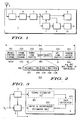
- FIG. 1 shows an OFDM receiver 1.
- the OFDM receiver 1 includes an antenna 2 coupled to an RF front end module 3, the RF front end module 3 is coupled to a synchronisation unit 4, the synchronisation unit 4 is coupled to a demodulation unit 5, the demodulation unit 5 is coupled to a phase offset compensation unit 6 and an equalisation unit 7 with the equalisation unit 7 also being coupled to the phase offset compensation unit 6, the phase offset compensation unit 6 is coupled a data decoder 8.
- the phase offset compensation unit 6 and equalisation unit 7 are also coupled to a signal to noise and interference ratio measurement unit 9, according to an embodiment of the present invention, as described below.
- the signal to noise and interference ration measurement unit 9 is coupled to a link adaptation module 10.
- the OFDM receiver 1 receives an OFDM signal over a communication channel and demodulates the time domain symbols into frequency domain sub-carrier via the demodulation unit 5 and decodes data received over this channel via the data decoder 8, as is well known to a person skilled in the art.
- the equalisation unit 7 compensates for the attenuation due to the frequency selective channel by first measuring the channel coefficients during channel coefficient estimation, which consist in storing the non-zero sub-carrier information receiving during the preamble long symbol, and then compensating the data sub-carriers either by dividing them by the channel coefficients or by multiplying them by the complex conjugate of the channel coefficients if just the phase needs to be compensated, as is well known to a person skilled in the art.
- the phase offset compensation unit 6 compensates for the frequency offset that exists between the transmitter and the receiver carrier central frequency. OFDM transceivers are very sensitive to this frequency offset, a first frequency offset compensation is implemented in the time domain (in the synchronization unit 4). However a second phase compensation is implemented in the frequency domain in the phase error compensation unit 6 that is more refined and can be recalculated for each symbol.
- the phase error compensation unit 6 applies phase compensation to the data symbols by rotating each sub-carrier with the opposite of the phase error that occur on sub-carrier i for symbol k (i.e.
- phase error is partly derived from the frequency offset which is measured by the synchronization unit 4 when the preamble is received.
- the phase error compensation is implemented by multiplying each data sub-carrier by a complex number:
- the data transmitted as part of the down link traffic 203 is contained within bursts 206 that consists of a preamble part 207 and protocol data units 208.
- the preamble part 207 comprises a cyclic prefix and two training symbols (not shown), where the training symbols are used by the equalisation unit 7 to perform a channel coefficient estimation H , as is well known to a person skilled in the art.
- FIG. 3 shows the signal to noise/interference ratio measurement unit 9.
- the signal to noise and interference ratio measurement unit 9 includes a signal power estimator module 301, a pilot noise and interference power module 302 and a signal to noise/interference ratio calculator module 303.
- the signal power estimator module 301 receives channel coefficient estimation information from the equalisation unit 7, the pilot noise and interference power module 302 receives phase information from the phase offset compensation unit 6 and the signal to noise/ interference ratio calculator module 303 is coupled to the output of both the signal power estimator module 301 and the pilot noise and interference power module 302 to allow calculation of a signal to noise/interference ratio 303 for a received signal, as described below.
- the signal to noise/interference ratio measurement unit 9 is arranged to calculate the SNIR, which is used to determine the link quality of a communication link, on a symbol by symbol basis (i.e. the SNIR is determined over the 52 sub-carriers).
- the equalisation unit 7 calculates a channel coefficient estimation H over each sub-carrier using training symbol information contained with the preamble of an OFDM burst.
- the channel coefficient estimation can be, for more accuracy, derived from the average of the two training symbols contained within the preamble.
- the average signal power value is provided to the signal to noise/interference ratio calculator module 303.
- the pilot noise and interference power module 302 calculates the average energy of the sub-carrier variations for the associated pilot information, transmitted over the four pilot sub-carriers, as described below.
- the noise and interference energy value NI 2 (k) is provided to the signal to noise/interference ratio calculator module 303.
- the signal to noise/interference ratio calculator module 303 provides the SNIR information to the link adaptation module 10.
- the link adaptation module 10 uses the SNIR information to determine an appropriate modulation mode for modulating data to be communicated over the communication link.
- link adaptation algorithm that can be used by the link adaptation module 10, for determining a suitable modulation mode, is described below.
- the link adaptation algorithm is based upon the assumption that the channel type, characterised by its delay spread, is stable and does not vary when the receiver 1 stays within the same environment and, as such, it is possible to combine the SNIR with some PER measurement.
- the algorithm comprises the following steps for a received frame:
- the same process is executed, if the PER is above PER_MAX, the correction factor is increased (it can be incremented for each wrong frame to converge more quickly). After reaching a PER below PER_MAX we know that an optimum correction value corresponding to the channel delay spread has been selected.
Description
- The present invention relates to a device and method for determining link quality for an OFDM communication link.
- Orthogonal Frequency Division Multiplex OFDM is a special form of multicarrier modulation that is arranged to provide high data rate communication by modulating data onto a plurality of sub-carriers. Wireless Local Area Network WLAN standards 802.11a and Hiperlan/2 are two examples of systems that have adopted OFDM modulation where for each system a data symbol is modulated onto 48 data sub-carriers with the use of 4 pilot sub-carriers to facilitate phase tracking to allow for coherent demodulation.
- OFDM systems are arranged to provide several modulation and coding alternatives, where each modulation and coding alternative allows different types of data mapping onto the respective data sub-carriers.
- For example, seven physical layer modes are defined in the HiperLAN/2 specification ranging from a physical layer bit rate of 6 Mbps for Binary Phase Shift Key BPSK to 54 Mbps for 64 Quadrature Amplitude Modulation 64QAM.
- During transmission and reception of an OFDM signal the signal will be attenuated and distorted by a frequency selective channel (i.e. the signals transmitted on the individual sub-carriers will be attenuated and distorted by different amounts dependent upon the environment where the channel characteristics are defined by a channel coefficient) in addition to noise and/or interference being added to the signal on each sub-carrier. The combination of noise and/or interference defines the quality of a communication channel (i.e. communication link) and is called the link quality.
- The selection of a suitable modulation scheme is dependent upon the link quality of a communication link, such that if a selected data rate is not matched to the relevant link quality for a communication link data may either be lost, if the data rate selected is too fast for the given link quality, or a communication link may be under utilised.
- However due to the variable environmental conditions of a wireless system the link quality of a communication link will fluctuate over a period of time. Consequently, OFDM systems are arranged to dynamically select an appropriate modulation and coding rate parameter using a link adaptation procedure to dynamically measure link quality and selecting an appropriate modulation scheme.
- One technique that is used for measuring the link quality is based upon frame error rate estimates that are obtained from cyclic redundancy checks CRC on decoded received data. This technique requires the reception of many frames of data to obtain reliable information, which for a communication link with rapidly changing link quality is undesirable.
- Another technique for measuring the link quality, as described in
US 2002/0110138 A1 , is based upon a signal to noise ratio measurement that is performed on training symbols within the preamble, which are transmitted as part of a data burst on the data sub-carriers, and using data symbols that having been demodulated and decoded are re-encoded and re-modulated. This technique can be complex, requiring additional processing power, and can introduce additional errors. - It is desirable to improve this situation.
- In accordance with a first aspect of the present invention there is provided a device according to claim 1.
- Preferably the means for determining the signal power calculates the signal power using a channel coefficient determined from a training symbol.
- Preferably the means for determining the signal power calculates an average signal power for a communication link having 48 data sub-carriers and 4 pilot sub-carriers based on the following equation:

where Hi is the channel coefficient for the i sub-carrier. - Preferably the characteristic of the pilot signal that is compared with the channel coefficient is the phase of the pilot signal.
- Preferably the distortion measurement for a communication link having 4 pilot sub-carriers is based on the following equation:

where Hi is the channel coefficient for the i sub-carrier, Pi is the phase and amplitude for the i pilot sub-carrier, k is for the k symbol and e-jφ comp,i(k) is a phase compensation value for the k symbol. - Preferably for a pilot signal that has been scrambled the noise and interference value for a communication link having 4 pilot sub-carriers is based on the following equation:

where Hi is the channel coefficient for the i pilot sub-carrier, Pi is the phase and amplitude for the i sub-carrier, k is for the k symbol, e-jφ comp,ik) is a phase compensation value for the k symbol and Di(k) is a descrambling function. - In accordance with a second aspect of the present invention there is provided a method for determining link quality of an OFDM communication link according to
claim 6. - This provides the advantage of allowing a link quality measurement to be made before the receipt of a whole frame and typically only requiring receipt of the preamble plus a few symbols before a good approximation of the link quality of a communication link can be performed. Further, this also provides the advantage of not requiring additional calculation to recode and remodulate a frame.
- An embodiment of the invention will now be described, by way of example, with reference to the drawings, of which:
-
Figure 1 shows an OFDM receiver according to an embodiment of the present invention; -
Figure 2 shows a OFDM media access frame; -
Figure 3 shows a signal to noise/interference ratio measurement unit according to an embodiment of the present invention. - The following embodiment is based upon a HIPERLAN/2 OFDM WLAN system, where a communication channel is defined as having a bandwidth of 20MHz, having 52 non-zero sub-carriers spaced 312.5 kHz apart, where the 52 sub-carriers consist of 48 data sub-carriers and 4 pilot sub-carriers. However, any form of OFDM based system may be used that may have a different number of data and pilot sub-carriers.
-
Figure 1 shows an OFDM receiver 1. The OFDM receiver 1 includes anantenna 2 coupled to an RFfront end module 3, the RFfront end module 3 is coupled to asynchronisation unit 4, thesynchronisation unit 4 is coupled to ademodulation unit 5, thedemodulation unit 5 is coupled to a phaseoffset compensation unit 6 and anequalisation unit 7 with theequalisation unit 7 also being coupled to the phaseoffset compensation unit 6, the phaseoffset compensation unit 6 is coupled adata decoder 8. The phaseoffset compensation unit 6 andequalisation unit 7 are also coupled to a signal to noise and interferenceratio measurement unit 9, according to an embodiment of the present invention, as described below. The signal to noise and interferenceration measurement unit 9 is coupled to alink adaptation module 10. - The OFDM receiver 1 receives an OFDM signal over a communication channel and demodulates the time domain symbols into frequency domain sub-carrier via the
demodulation unit 5 and decodes data received over this channel via thedata decoder 8, as is well known to a person skilled in the art. - The
equalisation unit 7 compensates for the attenuation due to the frequency selective channel by first measuring the channel coefficients during channel coefficient estimation, which consist in storing the non-zero sub-carrier information receiving during the preamble long symbol, and then compensating the data sub-carriers either by dividing them by the channel coefficients or by multiplying them by the complex conjugate of the channel coefficients if just the phase needs to be compensated, as is well known to a person skilled in the art. - The phase
offset compensation unit 6 compensates for the frequency offset that exists between the transmitter and the receiver carrier central frequency. OFDM transceivers are very sensitive to this frequency offset, a first frequency offset compensation is implemented in the time domain (in the synchronization unit 4). However a second phase compensation is implemented in the frequency domain in the phaseerror compensation unit 6 that is more refined and can be recalculated for each symbol. The phaseerror compensation unit 6 applies phase compensation to the data symbols by rotating each sub-carrier with the opposite of the phase error that occur on sub-carrier i for symbol k (i.e. φerror,i(k): φcomp,i(k)= -φerror,i(k))- The phase error is partly derived from the frequency offset which is measured by thesynchronization unit 4 when the preamble is received. The phase error compensation is implemented by multiplying each data sub-carrier by a complex number: -
Figure 2 illustrates a HIPERLAN/2 medium access controlMAC transmission frame 200. TheMAC frame 200 consists of a broadcast control channel BCCH 201 followed by a frame control channel FCC 202 followed by therespective downlink traffic 203 and uplinktraffic 204 that is followed by arandom access channel 205. - The data transmitted as part of the down
link traffic 203 is contained withinbursts 206 that consists of apreamble part 207 andprotocol data units 208. - The
preamble part 207 comprises a cyclic prefix and two training symbols (not shown), where the training symbols are used by theequalisation unit 7 to perform a channel coefficient estimation H, as is well known to a person skilled in the art. -
Figure 3 shows the signal to noise/interferenceratio measurement unit 9. The signal to noise and interferenceratio measurement unit 9 includes a signalpower estimator module 301, a pilot noise andinterference power module 302 and a signal to noise/interferenceratio calculator module 303. - The signal
power estimator module 301 receives channel coefficient estimation information from theequalisation unit 7, the pilot noise andinterference power module 302 receives phase information from the phaseoffset compensation unit 6 and the signal to noise/ interferenceratio calculator module 303 is coupled to the output of both the signalpower estimator module 301 and the pilot noise andinterference power module 302 to allow calculation of a signal to noise/interference ratio 303 for a received signal, as described below. - The signal to noise/interference
ratio measurement unit 9 is arranged to calculate the SNIR, which is used to determine the link quality of a communication link, on a symbol by symbol basis (i.e. the SNIR is determined over the 52 sub-carriers). - For each received symbol the
equalisation unit 7 calculates a channel coefficient estimation H over each sub-carrier using training symbol information contained with the preamble of an OFDM burst. For the purposes of this embodiment, the channel coefficient estimation can be, for more accuracy, derived from the average of the two training symbols contained within the preamble. - Using the channel coefficient estimation H provided by the
equalisation unit 7 the signalpower estimator module 301 calculates the average signal power for each of the sub-carriers using the following equation:
- The average signal power value is provided to the signal to noise/interference
ratio calculator module 303. - For each received data symbol k, which is received over the 48 data sub-carriers, the pilot noise and
interference power module 302 calculates the average energy of the sub-carrier variations for the associated pilot information, transmitted over the four pilot sub-carriers, as described below. - First, the noise and interference NIi(k) of a pilot signal associated with a received data symbol k is calculated by the pilot noise and
interference power module 302 by subtracting the pilot sub-carrier Pi(k) received with the kth symbol, having been corrected for phase compensation, from the pilot sub-carrier channel coefficient estimate Hi, as given by the following equation:
- Having calculated the noise and interference NIi(k) of the pilot signals the pilot noise and
interference power module 302 then calculates the average energy for the pilot signal noise and interference associated with the kth symbol using the following equation:
- The noise and interference energy value NI2(k) is provided to the signal to noise/interference
ratio calculator module 303. - Using the received values of S2 and NI2(k) the signal to noise/interference
ratio calculator module 303 calculates a SNIR for the kth symbol, in decibels, using the following equation:

- Having calculated a SNIR for a given symbol the signal to noise and
interference calculator module 303 can also average the calculated SNIR for all the symbols in a frame or over N frames:
- If the transmitted symbols have been scrambled by the transmitting node the above equations can be modified to include an appropriate descrambling function (i.e. Di(k)). Accordingly, the above equations can be modified as follows:


- The signal to noise/interference
ratio calculator module 303 provides the SNIR information to thelink adaptation module 10. Thelink adaptation module 10 uses the SNIR information to determine an appropriate modulation mode for modulating data to be communicated over the communication link. - In order to perform optimum link adaptation (i.e. determination and selection of an appropriate modulation mode) it is desirable to combine the SNIR measurement with information about the channel type (e.g. delay spread).
- One example of a link adaptation algorithm that can be used by the
link adaptation module 10, for determining a suitable modulation mode, is described below. The link adaptation algorithm is based upon the assumption that the channel type, characterised by its delay spread, is stable and does not vary when the receiver 1 stays within the same environment and, as such, it is possible to combine the SNIR with some PER measurement. - The algorithm comprises the following steps for a received frame:
- (i) Using simulation to obtaining a table containing the data rate as a function of the SNR for the default channel type (the most probable one) and stored this table in MAC software memory;
- (ii) For each received frame the PER is checked and if it is above PER_MAX
(a typical value can be 0.01) then a correction factor SNIR_COR is incremented by 1 but if the PER is below a second treshold PER_MIN (typically 0.001) it is decremented by 1 and if the PER is between these 2 tresholds, SNIR_COR is not updated; - (iii) Obtaining the optimum data rate by reading the data rate table with SNIR-SNIR_COR.
- At the next frame, the same process is executed, if the PER is above PER_MAX, the correction factor is increased (it can be incremented for each wrong frame to converge more quickly). After reaching a PER below PER_MAX we know that an optimum correction value corresponding to the channel delay spread has been selected.
- It will be apparent to those skilled in the art that the disclosed subject matter may be modified in numerous ways and may assume, for example, OFDM systems having any number of data and pilot sub-carriers.
Claims (6)
- A device for determining link quality of an OFDM communication link having a pilot sub-carrier, the device comprising means for determining a signal power of an OFDM signal transmitted over the OFDM communication link; and means for calculating a noise and interference value for a pilot signal associated with a received data symbol by subtracting a pilot subcarrier Pi(k) received with the received data symbol from a pilot sub-carrier channel coefficient estimate H1 wherein the pilot subcarrier Pi(k); and means for has been corrected for phase compensation determining a modulation mode based upon the ratio of the signal power of the received data symbol to the noise and interference value.
- A device according to claim 1, wherein the means for determining the signal power calculates the signal power using a channel coefficient determined from a training symbol.
- A device according to claim 2, wherein the means for determining the signal power calculates an average signal power for a communication link having 48 data sub-carriers and 4 pilot sub-carriers based on the following equation:

where Hi is the channel coefficient for the i sub-carrier. - A device according to any preceding claim, wherein the noise and interference value for a communication link having 4 pilot sub-carriers is based on the following equation:

where Hi is the channel coefficient for the i sub-carrier, Pi is the phase and amplitude for the i pilot sub-carrier, k is for the k symbol and e-jφ comp,i(k) is a phase compensation value for the k symbol. - A device according to claim 4, wherein for a pilot signal that has been scrambled the noise and interference value for a communication link having 4 pilot sub-carriers is based on the following equation:

where Hi is the channel coefficient for the i pilot sub-carrier, Pi is the phase and amplitude for the i sub-carrier, k is for the k symbol, e-jφ comp,i(k) is a phase compensation value for the k symbol and Di(k) is a descrambling function. - A method for determining link quality of an OFDM communication link having a pilot sub-carrier, the method comprising determining a signal power of an OFDM signal transmitted over the OFDM communication link; calculating a noise and interference value for a pilot signal associated with a received data symbol by subtracting a pilot sub carrier Pi(k) received with the received data symbol from a pilot sub-carrier channel coefficient estimate Hi, wherein the pilot subcarrier Pi(k) has been corrected for phase compensation, and determining a modulation mode based upon the ratio of the signal power of the received data symbol to the noise and interference value.
Priority Applications (4)
| Application Number | Priority Date | Filing Date | Title |
|---|---|---|---|
| EP03291809A EP1499059B1 (en) | 2003-07-18 | 2003-07-18 | Method and device for determining the link quality in an OFDM network |
| KR1020067001071A KR101109996B1 (en) | 2003-07-18 | 2004-06-25 | Method and device for determining the link quality in an ofdm network |
| PCT/EP2004/051249 WO2005015813A1 (en) | 2003-07-18 | 2004-06-25 | Method and device for determining the link quality in an ofdm network |
| CN2004800200888A CN1823490B (en) | 2003-07-18 | 2004-06-25 | Method and device for determining the link quality in an OFDM network |
Applications Claiming Priority (1)
| Application Number | Priority Date | Filing Date | Title |
|---|---|---|---|
| EP03291809A EP1499059B1 (en) | 2003-07-18 | 2003-07-18 | Method and device for determining the link quality in an OFDM network |
Publications (2)
| Publication Number | Publication Date |
|---|---|
| EP1499059A1 EP1499059A1 (en) | 2005-01-19 |
| EP1499059B1 true EP1499059B1 (en) | 2011-07-06 |
Family
ID=33462262
Family Applications (1)
| Application Number | Title | Priority Date | Filing Date |
|---|---|---|---|
| EP03291809A Expired - Lifetime EP1499059B1 (en) | 2003-07-18 | 2003-07-18 | Method and device for determining the link quality in an OFDM network |
Country Status (4)
| Country | Link |
|---|---|
| EP (1) | EP1499059B1 (en) |
| KR (1) | KR101109996B1 (en) |
| CN (1) | CN1823490B (en) |
| WO (1) | WO2005015813A1 (en) |
Families Citing this family (14)
| Publication number | Priority date | Publication date | Assignee | Title |
|---|---|---|---|---|
| CN1917501B (en) * | 2006-09-19 | 2010-09-08 | 华为技术有限公司 | Method and device for measuring ratio between interference and noise of carrier |
| CN101282166B (en) * | 2007-04-04 | 2012-10-10 | 中兴通讯股份有限公司 | Distribution method for dynamically scheduling physics channel training code |
| JP4924201B2 (en) * | 2007-05-23 | 2012-04-25 | 日本電気株式会社 | Reception quality measuring apparatus and reception quality measuring method |
| US8279743B2 (en) * | 2007-05-31 | 2012-10-02 | Telefonaktiebolaget Lm Ericsson (Publ) | Method for interference estimation for orthogonal pilot patterns |
| CN101689952B (en) * | 2007-06-29 | 2013-06-05 | 汤姆逊许可公司 | Apparatus and method for removing common phase error in a DVB-T/H receiver |
| CN101690060B (en) | 2007-06-29 | 2012-09-26 | 汤姆逊许可公司 | Apparatus and method for removing common phase error in a dvb-t/h receiver |
| US8532605B2 (en) | 2007-08-09 | 2013-09-10 | Intel Mobile Communications GmbH | Determining a receiving quality in a radio communication device |
| DE602007012243D1 (en) * | 2007-08-30 | 2011-03-10 | Ericsson Telefon Ab L M | Estimation of a signal-to-interference ratio at a receiver of a wireless communication system |
| CN102238111A (en) * | 2010-04-23 | 2011-11-09 | 中兴通讯股份有限公司 | Signal interference detection method and device |
| US8605839B2 (en) | 2010-09-21 | 2013-12-10 | Qualcomm Incorporated | System and method for reducing power consumption in a FLO-EV receiver |
| CN102694593B (en) * | 2012-05-30 | 2015-04-15 | 武汉邮电科学研究院 | Testing method of spectrum feature of optical passive device |
| KR102027828B1 (en) * | 2013-08-14 | 2019-10-04 | 삼성전자 주식회사 | Method and apparatus for estimating channel information |
| AT517364B1 (en) * | 2015-06-24 | 2020-01-15 | Siemens Ag Oesterreich | Method and communication system for wireless data transmission over a local radio network |
| CN108736919B (en) * | 2017-04-14 | 2020-05-26 | 大唐移动通信设备有限公司 | Noise power estimation method and device |
Family Cites Families (5)
| Publication number | Priority date | Publication date | Assignee | Title |
|---|---|---|---|---|
| US6308082B1 (en) * | 1998-10-06 | 2001-10-23 | Telefonaktiebolaget L M Ericsson (Publ) | Cell-level throughput adjustment in digital cellular systems |
| JP4287536B2 (en) * | 1998-11-06 | 2009-07-01 | パナソニック株式会社 | OFDM transmitter / receiver and OFDM transmitter / receiver method |
| US6865233B1 (en) * | 1999-02-19 | 2005-03-08 | Telefonaktiebolaget Lm Ericsson (Publ) | Method and system for control signalling enabling flexible link adaptation in a radiocommunication system |
| EP1176750A1 (en) * | 2000-07-25 | 2002-01-30 | Telefonaktiebolaget L M Ericsson (Publ) | Link quality determination of a transmission link in an OFDM transmission system |
| US6563885B1 (en) * | 2001-10-24 | 2003-05-13 | Texas Instruments Incorporated | Decimated noise estimation and/or beamforming for wireless communications |
-
2003
- 2003-07-18 EP EP03291809A patent/EP1499059B1/en not_active Expired - Lifetime
-
2004
- 2004-06-25 KR KR1020067001071A patent/KR101109996B1/en active IP Right Grant
- 2004-06-25 WO PCT/EP2004/051249 patent/WO2005015813A1/en active Application Filing
- 2004-06-25 CN CN2004800200888A patent/CN1823490B/en active Active
Non-Patent Citations (1)
| Title |
|---|
| None * |
Also Published As
| Publication number | Publication date |
|---|---|
| CN1823490B (en) | 2010-06-16 |
| EP1499059A1 (en) | 2005-01-19 |
| WO2005015813A1 (en) | 2005-02-17 |
| KR20060063893A (en) | 2006-06-12 |
| KR101109996B1 (en) | 2012-01-31 |
| CN1823490A (en) | 2006-08-23 |
Similar Documents
| Publication | Publication Date | Title |
|---|---|---|
| US20210075572A1 (en) | Method and apparatus for generating pilot tone in orthogonal frequency division multiplexing access system, and method and apparatus for estimating channel using it | |
| US7822069B2 (en) | Phase correction for OFDM and MIMO transmissions | |
| US8477891B2 (en) | Noise estimation for wireless communication | |
| US7580467B2 (en) | System and method for multiple signal carrier time domain channel estimation | |
| US7573944B2 (en) | Apparatus and method for canceling inter-symbol interference in a broadband wireless communication system | |
| EP1303937B1 (en) | Link quality determination of a transmission link in an ofdm transmission system | |
| US7280504B2 (en) | OFDM transmitting and receiving apparatus | |
| US20040100898A1 (en) | Method and apparatus for channel quality metric generation within a packet-based multicarrier modulation communication system | |
| US20060221807A1 (en) | Multi-carrier transmitter apparatus, multi-carrier receiver apparatus and multi-carrier communication method | |
| EP1499059B1 (en) | Method and device for determining the link quality in an OFDM network | |
| JP3492565B2 (en) | OFDM communication device and detection method | |
| US20040203465A1 (en) | Mode adaptation in wireless systems | |
| EP1434381B1 (en) | Link adaptation process | |
| US20070127361A1 (en) | Ofdm transmission apparatus, ofdm reception apparatus, and method | |
| JP3534020B2 (en) | Demodulation circuit for multi-carrier modulation method | |
| JP2008022339A (en) | Radio communication device and radio communication method |
Legal Events
| Date | Code | Title | Description |
|---|---|---|---|
| PUAI | Public reference made under article 153(3) epc to a published international application that has entered the european phase |
Free format text: ORIGINAL CODE: 0009012 |
|
| AK | Designated contracting states |
Kind code of ref document: A1 Designated state(s): AT BE BG CH CY CZ DE DK EE ES FI FR GB GR HU IE IT LI LU MC NL PT RO SE SI SK TR |
|
| AX | Request for extension of the european patent |
Extension state: AL LT LV MK |
|
| 17P | Request for examination filed |
Effective date: 20050511 |
|
| AKX | Designation fees paid |
Designated state(s): DE FR GB IT |
|
| APBN | Date of receipt of notice of appeal recorded |
Free format text: ORIGINAL CODE: EPIDOSNNOA2E |
|
| APBR | Date of receipt of statement of grounds of appeal recorded |
Free format text: ORIGINAL CODE: EPIDOSNNOA3E |
|
| APAF | Appeal reference modified |
Free format text: ORIGINAL CODE: EPIDOSCREFNE |
|
| APAF | Appeal reference modified |
Free format text: ORIGINAL CODE: EPIDOSCREFNE |
|
| APBT | Appeal procedure closed |
Free format text: ORIGINAL CODE: EPIDOSNNOA9E |
|
| GRAP | Despatch of communication of intention to grant a patent |
Free format text: ORIGINAL CODE: EPIDOSNIGR1 |
|
| RAP1 | Party data changed (applicant data changed or rights of an application transferred) |
Owner name: MOTOROLA MOBILITY, INC. |
|
| GRAS | Grant fee paid |
Free format text: ORIGINAL CODE: EPIDOSNIGR3 |
|
| GRAA | (expected) grant |
Free format text: ORIGINAL CODE: 0009210 |
|
| AK | Designated contracting states |
Kind code of ref document: B1 Designated state(s): DE FR GB IT |
|
| REG | Reference to a national code |
Ref country code: GB Ref legal event code: FG4D |
|
| REG | Reference to a national code |
Ref country code: DE Ref legal event code: R081 Ref document number: 60337618 Country of ref document: DE Owner name: GOOGLE TECHNOLOGY HOLDINGS LLC, MOUNTAIN VIEW, US Free format text: FORMER OWNER: MOTOROLA, INC., SCHAUMBURG, ILL., US |
|
| REG | Reference to a national code |
Ref country code: DE Ref legal event code: R096 Ref document number: 60337618 Country of ref document: DE Effective date: 20110908 |
|
| PLBE | No opposition filed within time limit |
Free format text: ORIGINAL CODE: 0009261 |
|
| STAA | Information on the status of an ep patent application or granted ep patent |
Free format text: STATUS: NO OPPOSITION FILED WITHIN TIME LIMIT |
|
| PG25 | Lapsed in a contracting state [announced via postgrant information from national office to epo] |
Ref country code: IT Free format text: LAPSE BECAUSE OF FAILURE TO SUBMIT A TRANSLATION OF THE DESCRIPTION OR TO PAY THE FEE WITHIN THE PRESCRIBED TIME-LIMIT Effective date: 20110706 |
|
| 26N | No opposition filed |
Effective date: 20120411 |
|
| REG | Reference to a national code |
Ref country code: DE Ref legal event code: R097 Ref document number: 60337618 Country of ref document: DE Effective date: 20120411 |
|
| REG | Reference to a national code |
Ref country code: FR Ref legal event code: PLFP Year of fee payment: 14 |
|
| REG | Reference to a national code |
Ref country code: FR Ref legal event code: PLFP Year of fee payment: 15 |
|
| REG | Reference to a national code |
Ref country code: GB Ref legal event code: 732E Free format text: REGISTERED BETWEEN 20170831 AND 20170906 |
|
| REG | Reference to a national code |
Ref country code: FR Ref legal event code: CD Owner name: GOOGLE TECHNOLOGY HOLDINGS LLC, US Effective date: 20171214 Ref country code: FR Ref legal event code: TP Owner name: GOOGLE TECHNOLOGY HOLDINGS LLC, US Effective date: 20171214 |
|
| REG | Reference to a national code |
Ref country code: DE Ref legal event code: R082 Ref document number: 60337618 Country of ref document: DE Representative=s name: BETTEN & RESCH PATENT- UND RECHTSANWAELTE PART, DE Ref country code: DE Ref legal event code: R081 Ref document number: 60337618 Country of ref document: DE Owner name: GOOGLE TECHNOLOGY HOLDINGS LLC, MOUNTAIN VIEW, US Free format text: FORMER OWNER: MOTOROLA MOBILITY, INC., LIBERTYVILLE, ILL., US |
|
| REG | Reference to a national code |
Ref country code: FR Ref legal event code: PLFP Year of fee payment: 16 |
|
| PGFP | Annual fee paid to national office [announced via postgrant information from national office to epo] |
Ref country code: FR Payment date: 20210726 Year of fee payment: 19 |
|
| PGFP | Annual fee paid to national office [announced via postgrant information from national office to epo] |
Ref country code: GB Payment date: 20220727 Year of fee payment: 20 Ref country code: DE Payment date: 20220727 Year of fee payment: 20 |
|
| PG25 | Lapsed in a contracting state [announced via postgrant information from national office to epo] |
Ref country code: FR Free format text: LAPSE BECAUSE OF NON-PAYMENT OF DUE FEES Effective date: 20220731 |
|
| P01 | Opt-out of the competence of the unified patent court (upc) registered |
Effective date: 20230516 |
|
| REG | Reference to a national code |
Ref country code: DE Ref legal event code: R071 Ref document number: 60337618 Country of ref document: DE |
|
| REG | Reference to a national code |
Ref country code: GB Ref legal event code: PE20 Expiry date: 20230717 |
|
| PG25 | Lapsed in a contracting state [announced via postgrant information from national office to epo] |
Ref country code: GB Free format text: LAPSE BECAUSE OF EXPIRATION OF PROTECTION Effective date: 20230717 |