EP1499041A1 - Laser device for optical packet data transmission in burst mode systems - Google Patents
Laser device for optical packet data transmission in burst mode systems Download PDFInfo
- Publication number
- EP1499041A1 EP1499041A1 EP03291778A EP03291778A EP1499041A1 EP 1499041 A1 EP1499041 A1 EP 1499041A1 EP 03291778 A EP03291778 A EP 03291778A EP 03291778 A EP03291778 A EP 03291778A EP 1499041 A1 EP1499041 A1 EP 1499041A1
- Authority
- EP
- European Patent Office
- Prior art keywords
- laser light
- packet data
- laser
- light source
- data stream
- Prior art date
- Legal status (The legal status is an assumption and is not a legal conclusion. Google has not performed a legal analysis and makes no representation as to the accuracy of the status listed.)
- Granted
Links
- 230000003287 optical effect Effects 0.000 title claims abstract description 39
- 230000005540 biological transmission Effects 0.000 title claims abstract description 9
- 230000004044 response Effects 0.000 claims abstract description 26
- 230000009977 dual effect Effects 0.000 claims description 12
- 230000000295 complement effect Effects 0.000 claims description 9
- 239000000945 filler Substances 0.000 claims description 8
- 239000013307 optical fiber Substances 0.000 claims description 6
- 230000008901 benefit Effects 0.000 description 3
- 230000008033 biological extinction Effects 0.000 description 3
- 230000008878 coupling Effects 0.000 description 2
- 238000010168 coupling process Methods 0.000 description 2
- 238000005859 coupling reaction Methods 0.000 description 2
- 239000003990 capacitor Substances 0.000 description 1
- 230000001419 dependent effect Effects 0.000 description 1
- 238000001514 detection method Methods 0.000 description 1
- 239000000835 fiber Substances 0.000 description 1
- 230000006872 improvement Effects 0.000 description 1
- 238000000034 method Methods 0.000 description 1
Images


Classifications
-
- H—ELECTRICITY
- H04—ELECTRIC COMMUNICATION TECHNIQUE
- H04B—TRANSMISSION
- H04B10/00—Transmission systems employing electromagnetic waves other than radio-waves, e.g. infrared, visible or ultraviolet light, or employing corpuscular radiation, e.g. quantum communication
- H04B10/50—Transmitters
- H04B10/572—Wavelength control
Landscapes
- Physics & Mathematics (AREA)
- Electromagnetism (AREA)
- Engineering & Computer Science (AREA)
- Computer Networks & Wireless Communication (AREA)
- Signal Processing (AREA)
- Optical Communication System (AREA)
- Semiconductor Lasers (AREA)
Abstract
Description
- Figure 1
- shows a first embodiment of the laser device according to the inventions;
- Figure 2a
- shows a packet data stream including filler patterns as output by a packet data source;
- Figure 2b
- shows a data packet;
- Figure 2c
- shows an envelope signal covering said data packet;
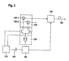
- Figure 3
- shows a second embodiment of the laser device according to the invention;
- Figure 4
- shows a third embodiment of the laser device according to the invention; and
- Figure 5
- shows an optical transmitter according to the invention.
Claims (9)
- Laser device (100) for optical packet data transmission in TDM-systems, comprising:characterized bya laser light source (130) for outputting laser light beam and a laser driver (120) for driving said laser light source (130);an optical modulator means (140) for receiving andmodulating the laser light beam output by said laser light source (130);a packet data source (110) for outputting a packet data stream; anda modulator driver (150) for receiving said packet data stream output by said packet data source (110) and for driving said optical modulator means (140) in response to said packet data stream resulting in that the optical modulator means (140) modulates the laser light beam in response to said packet data stream;
a filter means (112) for generating an envelope signal of the data packets (dp) in said packet data stream; and
a switching means (114) for switching the laser driver (120) in response to said envelope signal(es). - Laser device (100) according to claim 1, characterized in that the packet data stream comprises filler patterns (fp) between its data packets.
- Laser device (100) according to claim 1 or 2 characterized in that
the laser light source (130') is embodied as a dual power consuming unit comprising an active laser light source element (130'-1) for outputting the switched laser light beam as first power consuming element and a second power consuming element (130'-2), wherein both elements have identical electrical parameters and thermal losses and both are thightly thermally coupled; and
the laser driver (120') is embodied as differential driver for driving both elements (130'-1, 130'-2) in a complementary manner such that the sum of their driving currents is constant in the range of the thermal time constant of said dual power consuming unit (130'). - Laser device (100) according to claim 3, characterized in that the second power consuming element (130'-2) is embodied as blind laser light source element.
- Optical transmitter (200) in a TDM-system in particular in a DWDM-system, comprising
a laser device (100) according to one the preceding claims for outputting a laser light beam being modulated in response to a packet data stream onto an optical fiber (160) . - Laser device (100) for optical packet data transmission in DWDM-systems, comprising:characterized in thata laser light source (130') for outputting a laser light beam; a laser driver (120') for driving said laser light source (130'); anda packet data source (110') for outputting a packet data stream, wherein the laser light beam output by said laser light source (130') is modulated in response to said packet data stream;
the laser light source (130') is embodied as a dual power consuming unit comprising an active laser light source element (130'-1) for outputting the modulated laser light beam as first power consuming element and a second power consuming element (130'-2), wherein both elements have identical electrical parameters and thermal losses and both are thightly thermally coupled; and
the laser driver (120') is embodied as differential driver for driving both elements (130'-1, 130'-2) in a complementary manner such that the sum of their driving currents is constant in the range of the thermal time constant of said dual power consuming unit (130'). - Laser device (100) according to claim 6, characterized in that it further comprises:a filter means (112') for generating an envelope signal of the data packets (dp) in said packet data stream;a switching means (114') for switching the differential laser diver (120') in a complementary manner in response to said envelope signal, resulting in that said laser light source (130') is driven by said laser driver (120') in response to said envelope signal, too;an optical modulator means (140) for receiving the switched laser light beam output by said laser light source (130'); anda modulator driver (150) for receiving the packet data stream output by the packet data source (110') and for driving said optical modulator means (140) in response to said packet data stream resulting in that the optical modulator means (140) modulates the laser beam in response to said packet data stream.
- Laser device (100), according to claim 7, characterized in that the packet data stream comprises filler patterns (fp) between its data packets (dp).
- Optical transmitter (200') in a TDM-system, in particular a DWDM-system, comprising:a laser device according to one of the claims 6 to 8 for outputting a laser light beam being modulated in response to a packet data stream onto an optical fiver.
Priority Applications (7)
| Application Number | Priority Date | Filing Date | Title |
|---|---|---|---|
| AT06020659T ATE448610T1 (en) | 2003-07-17 | 2003-07-17 | LASER FOR OPTICAL PACKET DATA TRANSMISSION IN BURST MODE SYSTEMS |
| EP06020659A EP1737148B1 (en) | 2003-07-17 | 2003-07-17 | Laser device for optical packet data transmission in burst mode systems |
| DE60316789T DE60316789T2 (en) | 2003-07-17 | 2003-07-17 | Laser for optical packet data transmission in burst mode systems |
| AT03291778T ATE375639T1 (en) | 2003-07-17 | 2003-07-17 | LASER FOR OPTICAL PACKET DATA TRANSMISSION IN BURST MODE SYSTEMS |
| EP03291778A EP1499041B1 (en) | 2003-07-17 | 2003-07-17 | Laser device for optical packet data transmission in burst mode systems |
| DE60330076T DE60330076D1 (en) | 2003-07-17 | 2003-07-17 | Laser for optical packet data transmission in burst mode systems |
| US10/873,286 US7489879B2 (en) | 2003-07-17 | 2004-06-23 | Laser device for optical data transmission |
Applications Claiming Priority (1)
| Application Number | Priority Date | Filing Date | Title |
|---|---|---|---|
| EP03291778A EP1499041B1 (en) | 2003-07-17 | 2003-07-17 | Laser device for optical packet data transmission in burst mode systems |
Related Child Applications (1)
| Application Number | Title | Priority Date | Filing Date |
|---|---|---|---|
| EP06020659A Division EP1737148B1 (en) | 2003-07-17 | 2003-07-17 | Laser device for optical packet data transmission in burst mode systems |
Publications (2)
| Publication Number | Publication Date |
|---|---|
| EP1499041A1 true EP1499041A1 (en) | 2005-01-19 |
| EP1499041B1 EP1499041B1 (en) | 2007-10-10 |
Family
ID=33462250
Family Applications (2)
| Application Number | Title | Priority Date | Filing Date |
|---|---|---|---|
| EP06020659A Expired - Lifetime EP1737148B1 (en) | 2003-07-17 | 2003-07-17 | Laser device for optical packet data transmission in burst mode systems |
| EP03291778A Expired - Lifetime EP1499041B1 (en) | 2003-07-17 | 2003-07-17 | Laser device for optical packet data transmission in burst mode systems |
Family Applications Before (1)
| Application Number | Title | Priority Date | Filing Date |
|---|---|---|---|
| EP06020659A Expired - Lifetime EP1737148B1 (en) | 2003-07-17 | 2003-07-17 | Laser device for optical packet data transmission in burst mode systems |
Country Status (4)
| Country | Link |
|---|---|
| US (1) | US7489879B2 (en) |
| EP (2) | EP1737148B1 (en) |
| AT (2) | ATE375639T1 (en) |
| DE (2) | DE60330076D1 (en) |
Cited By (1)
| Publication number | Priority date | Publication date | Assignee | Title |
|---|---|---|---|---|
| RU2312371C1 (en) * | 2006-07-06 | 2007-12-10 | Владимир Миронович Вишневский | Mode of wireless communication over an atmosphere optical line and a system of wireless optical communication |
Families Citing this family (2)
| Publication number | Priority date | Publication date | Assignee | Title |
|---|---|---|---|---|
| US20080049825A1 (en) * | 2006-08-25 | 2008-02-28 | Broadcom Corporation | Equalizer with reorder |
| US20170250755A1 (en) * | 2016-02-29 | 2017-08-31 | Renesas Electronics Corporation | Semiconductor device |
Citations (2)
| Publication number | Priority date | Publication date | Assignee | Title |
|---|---|---|---|---|
| EP0683552A2 (en) * | 1994-05-20 | 1995-11-22 | CSELT Centro Studi e Laboratori Telecomunicazioni S.p.A. | Method and device for controlling the peak power of a laser transmitter in discontinuous optical transmission systems |
| US6590686B1 (en) * | 1998-12-24 | 2003-07-08 | Fujitsu Limited | Optical transmitter |
Family Cites Families (6)
| Publication number | Priority date | Publication date | Assignee | Title |
|---|---|---|---|---|
| DE4039371C2 (en) * | 1990-12-10 | 2000-05-31 | Zeiss Carl Fa | Device for stabilizing the wavelength of a laser diode |
| US6282340B1 (en) * | 1998-04-23 | 2001-08-28 | The Furukawa Electric Co., Ltd. | Light wavelength tuning device and light source optical demultiplexer and wavelength division multiplexed optical communication system using the tuning device |
| US6535313B1 (en) * | 1998-10-16 | 2003-03-18 | Lucent Technologies Inc. | Dynamically assignable optical signal access control apparatus |
| US6771750B1 (en) * | 1998-10-29 | 2004-08-03 | Advanced Micro Devices, Inc. | Physical layer transceiver architecture for a home network station connected to a telephone line medium |
| US6731877B1 (en) * | 2000-03-03 | 2004-05-04 | Qtera Corporation | High capacity ultra-long haul dispersion and nonlinearity managed lightwave communication systems |
| EP1261082A1 (en) * | 2001-05-25 | 2002-11-27 | Agilent Technologies, Inc. (a Delaware corporation) | Optoelectronic circuit and control circuit |
-
2003
- 2003-07-17 DE DE60330076T patent/DE60330076D1/en not_active Expired - Lifetime
- 2003-07-17 DE DE60316789T patent/DE60316789T2/en not_active Expired - Lifetime
- 2003-07-17 EP EP06020659A patent/EP1737148B1/en not_active Expired - Lifetime
- 2003-07-17 AT AT03291778T patent/ATE375639T1/en not_active IP Right Cessation
- 2003-07-17 EP EP03291778A patent/EP1499041B1/en not_active Expired - Lifetime
- 2003-07-17 AT AT06020659T patent/ATE448610T1/en not_active IP Right Cessation
-
2004
- 2004-06-23 US US10/873,286 patent/US7489879B2/en not_active Expired - Lifetime
Patent Citations (2)
| Publication number | Priority date | Publication date | Assignee | Title |
|---|---|---|---|---|
| EP0683552A2 (en) * | 1994-05-20 | 1995-11-22 | CSELT Centro Studi e Laboratori Telecomunicazioni S.p.A. | Method and device for controlling the peak power of a laser transmitter in discontinuous optical transmission systems |
| US6590686B1 (en) * | 1998-12-24 | 2003-07-08 | Fujitsu Limited | Optical transmitter |
Cited By (1)
| Publication number | Priority date | Publication date | Assignee | Title |
|---|---|---|---|---|
| RU2312371C1 (en) * | 2006-07-06 | 2007-12-10 | Владимир Миронович Вишневский | Mode of wireless communication over an atmosphere optical line and a system of wireless optical communication |
Also Published As
| Publication number | Publication date |
|---|---|
| ATE375639T1 (en) | 2007-10-15 |
| US7489879B2 (en) | 2009-02-10 |
| DE60330076D1 (en) | 2009-12-24 |
| EP1737148B1 (en) | 2009-11-11 |
| DE60316789D1 (en) | 2007-11-22 |
| EP1737148A3 (en) | 2007-08-01 |
| EP1499041B1 (en) | 2007-10-10 |
| ATE448610T1 (en) | 2009-11-15 |
| US20050013617A1 (en) | 2005-01-20 |
| DE60316789T2 (en) | 2008-07-17 |
| EP1737148A2 (en) | 2006-12-27 |
Similar Documents
| Publication | Publication Date | Title |
|---|---|---|
| US6115403A (en) | Directly modulated semiconductor laser having reduced chirp | |
| US6766116B2 (en) | Optical transmission system | |
| US8036534B2 (en) | Optical transmitter outputting a plurality of signal light with a preset wavelength span | |
| US5875273A (en) | Laser wavelength control under direct modulation | |
| EP0297504A3 (en) | Wavelength multiplexed optical transmitter | |
| GB2257320A (en) | An optical communication system | |
| EP0477875B1 (en) | A signal converting method, a transmitter, an optical communication system and a signal converting apparatus comprising said transmitter | |
| US7480464B2 (en) | Widely tunable, dispersion tolerant transmitter | |
| US20050031357A1 (en) | Controlling the extinction ratio in optical networks | |
| JP3511445B2 (en) | Optical two-way transmission system | |
| EP1499041A1 (en) | Laser device for optical packet data transmission in burst mode systems | |
| EP0591961B1 (en) | Fiber optic communication terminal, fiber optic communication system, and its wavelength setting method | |
| KR20080066893A (en) | Wavelength band division multiplexing communication system, apparatus and method thereof in optical wireless communication system | |
| JP2006515134A (en) | Asymmetric optical network traffic flow control | |
| US7031620B2 (en) | Optical transmission device and optical transmission system using the same | |
| JP2003110505A (en) | Optical transmitter and wavelength division multiplex transmission system | |
| JP2009033556A (en) | Optical transmitter | |
| GB2254746A (en) | Optical transmitter | |
| US6452953B1 (en) | Light source | |
| US20010040712A1 (en) | Reconfigurable optical recognition of bit information in a digital data stream with different bit rates | |
| JPH0669884A (en) | Optical parallel transmitter | |
| EP0458252B1 (en) | Long range bidirectional optical fiber communication link | |
| JP2009099862A (en) | Control circuit and temperature control method | |
| US10355784B2 (en) | Method and optical transmitter device for creating an optical binary digital transmit signal | |
| EP1873575A1 (en) | Optical modulation apparatus and method to control it |
Legal Events
| Date | Code | Title | Description |
|---|---|---|---|
| PUAI | Public reference made under article 153(3) epc to a published international application that has entered the european phase |
Free format text: ORIGINAL CODE: 0009012 |
|
| 17P | Request for examination filed |
Effective date: 20040806 |
|
| AK | Designated contracting states |
Kind code of ref document: A1 Designated state(s): AT BE BG CH CY CZ DE DK EE ES FI FR GB GR HU IE IT LI LU MC NL PT RO SE SI SK TR |
|
| AX | Request for extension of the european patent |
Extension state: AL LT LV MK |
|
| AKX | Designation fees paid |
Designated state(s): AT BE BG CH CY CZ DE DK EE ES FI FR GB GR HU IE IT LI LU MC NL PT RO SE SI SK TR |
|
| GRAP | Despatch of communication of intention to grant a patent |
Free format text: ORIGINAL CODE: EPIDOSNIGR1 |
|
| RAP1 | Party data changed (applicant data changed or rights of an application transferred) |
Owner name: ALCATEL LUCENT |
|
| GRAS | Grant fee paid |
Free format text: ORIGINAL CODE: EPIDOSNIGR3 |
|
| GRAA | (expected) grant |
Free format text: ORIGINAL CODE: 0009210 |
|
| AK | Designated contracting states |
Kind code of ref document: B1 Designated state(s): AT BE BG CH CY CZ DE DK EE ES FI FR GB GR HU IE IT LI LU MC NL PT RO SE SI SK TR |
|
| REG | Reference to a national code |
Ref country code: GB Ref legal event code: FG4D |
|
| REG | Reference to a national code |
Ref country code: CH Ref legal event code: EP |
|
| REG | Reference to a national code |
Ref country code: IE Ref legal event code: FG4D |
|
| REF | Corresponds to: |
Ref document number: 60316789 Country of ref document: DE Date of ref document: 20071122 Kind code of ref document: P |
|
| NLV1 | Nl: lapsed or annulled due to failure to fulfill the requirements of art. 29p and 29m of the patents act | ||
| PG25 | Lapsed in a contracting state [announced via postgrant information from national office to epo] |
Ref country code: SE Free format text: LAPSE BECAUSE OF FAILURE TO SUBMIT A TRANSLATION OF THE DESCRIPTION OR TO PAY THE FEE WITHIN THE PRESCRIBED TIME-LIMIT Effective date: 20080110 Ref country code: CH Free format text: LAPSE BECAUSE OF FAILURE TO SUBMIT A TRANSLATION OF THE DESCRIPTION OR TO PAY THE FEE WITHIN THE PRESCRIBED TIME-LIMIT Effective date: 20071010 Ref country code: LI Free format text: LAPSE BECAUSE OF FAILURE TO SUBMIT A TRANSLATION OF THE DESCRIPTION OR TO PAY THE FEE WITHIN THE PRESCRIBED TIME-LIMIT Effective date: 20071010 Ref country code: ES Free format text: LAPSE BECAUSE OF FAILURE TO SUBMIT A TRANSLATION OF THE DESCRIPTION OR TO PAY THE FEE WITHIN THE PRESCRIBED TIME-LIMIT Effective date: 20080121 Ref country code: NL Free format text: LAPSE BECAUSE OF FAILURE TO SUBMIT A TRANSLATION OF THE DESCRIPTION OR TO PAY THE FEE WITHIN THE PRESCRIBED TIME-LIMIT Effective date: 20071010 |
|
| REG | Reference to a national code |
Ref country code: CH Ref legal event code: PL |
|
| ET | Fr: translation filed | ||
| PG25 | Lapsed in a contracting state [announced via postgrant information from national office to epo] |
Ref country code: PT Free format text: LAPSE BECAUSE OF FAILURE TO SUBMIT A TRANSLATION OF THE DESCRIPTION OR TO PAY THE FEE WITHIN THE PRESCRIBED TIME-LIMIT Effective date: 20080310 Ref country code: BG Free format text: LAPSE BECAUSE OF FAILURE TO SUBMIT A TRANSLATION OF THE DESCRIPTION OR TO PAY THE FEE WITHIN THE PRESCRIBED TIME-LIMIT Effective date: 20080110 |
|
| PG25 | Lapsed in a contracting state [announced via postgrant information from national office to epo] |
Ref country code: AT Free format text: LAPSE BECAUSE OF FAILURE TO SUBMIT A TRANSLATION OF THE DESCRIPTION OR TO PAY THE FEE WITHIN THE PRESCRIBED TIME-LIMIT Effective date: 20071010 |
|
| PG25 | Lapsed in a contracting state [announced via postgrant information from national office to epo] |
Ref country code: DK Free format text: LAPSE BECAUSE OF FAILURE TO SUBMIT A TRANSLATION OF THE DESCRIPTION OR TO PAY THE FEE WITHIN THE PRESCRIBED TIME-LIMIT Effective date: 20071010 Ref country code: CZ Free format text: LAPSE BECAUSE OF FAILURE TO SUBMIT A TRANSLATION OF THE DESCRIPTION OR TO PAY THE FEE WITHIN THE PRESCRIBED TIME-LIMIT Effective date: 20071010 |
|
| PLBE | No opposition filed within time limit |
Free format text: ORIGINAL CODE: 0009261 |
|
| STAA | Information on the status of an ep patent application or granted ep patent |
Free format text: STATUS: NO OPPOSITION FILED WITHIN TIME LIMIT |
|
| PG25 | Lapsed in a contracting state [announced via postgrant information from national office to epo] |
Ref country code: RO Free format text: LAPSE BECAUSE OF FAILURE TO SUBMIT A TRANSLATION OF THE DESCRIPTION OR TO PAY THE FEE WITHIN THE PRESCRIBED TIME-LIMIT Effective date: 20071010 Ref country code: SK Free format text: LAPSE BECAUSE OF FAILURE TO SUBMIT A TRANSLATION OF THE DESCRIPTION OR TO PAY THE FEE WITHIN THE PRESCRIBED TIME-LIMIT Effective date: 20071010 Ref country code: BE Free format text: LAPSE BECAUSE OF FAILURE TO SUBMIT A TRANSLATION OF THE DESCRIPTION OR TO PAY THE FEE WITHIN THE PRESCRIBED TIME-LIMIT Effective date: 20071010 |
|
| 26N | No opposition filed |
Effective date: 20080711 |
|
| PG25 | Lapsed in a contracting state [announced via postgrant information from national office to epo] |
Ref country code: GR Free format text: LAPSE BECAUSE OF FAILURE TO SUBMIT A TRANSLATION OF THE DESCRIPTION OR TO PAY THE FEE WITHIN THE PRESCRIBED TIME-LIMIT Effective date: 20080111 |
|
| PG25 | Lapsed in a contracting state [announced via postgrant information from national office to epo] |
Ref country code: FI Free format text: LAPSE BECAUSE OF FAILURE TO SUBMIT A TRANSLATION OF THE DESCRIPTION OR TO PAY THE FEE WITHIN THE PRESCRIBED TIME-LIMIT Effective date: 20071010 |
|
| PG25 | Lapsed in a contracting state [announced via postgrant information from national office to epo] |
Ref country code: MC Free format text: LAPSE BECAUSE OF NON-PAYMENT OF DUE FEES Effective date: 20080731 |
|
| PG25 | Lapsed in a contracting state [announced via postgrant information from national office to epo] |
Ref country code: EE Free format text: LAPSE BECAUSE OF FAILURE TO SUBMIT A TRANSLATION OF THE DESCRIPTION OR TO PAY THE FEE WITHIN THE PRESCRIBED TIME-LIMIT Effective date: 20071010 |
|
| PG25 | Lapsed in a contracting state [announced via postgrant information from national office to epo] |
Ref country code: SI Free format text: LAPSE BECAUSE OF FAILURE TO SUBMIT A TRANSLATION OF THE DESCRIPTION OR TO PAY THE FEE WITHIN THE PRESCRIBED TIME-LIMIT Effective date: 20071010 |
|
| PG25 | Lapsed in a contracting state [announced via postgrant information from national office to epo] |
Ref country code: CY Free format text: LAPSE BECAUSE OF FAILURE TO SUBMIT A TRANSLATION OF THE DESCRIPTION OR TO PAY THE FEE WITHIN THE PRESCRIBED TIME-LIMIT Effective date: 20071010 Ref country code: IE Free format text: LAPSE BECAUSE OF NON-PAYMENT OF DUE FEES Effective date: 20080717 |
|
| PG25 | Lapsed in a contracting state [announced via postgrant information from national office to epo] |
Ref country code: LU Free format text: LAPSE BECAUSE OF NON-PAYMENT OF DUE FEES Effective date: 20080717 Ref country code: HU Free format text: LAPSE BECAUSE OF FAILURE TO SUBMIT A TRANSLATION OF THE DESCRIPTION OR TO PAY THE FEE WITHIN THE PRESCRIBED TIME-LIMIT Effective date: 20080411 |
|
| PG25 | Lapsed in a contracting state [announced via postgrant information from national office to epo] |
Ref country code: TR Free format text: LAPSE BECAUSE OF FAILURE TO SUBMIT A TRANSLATION OF THE DESCRIPTION OR TO PAY THE FEE WITHIN THE PRESCRIBED TIME-LIMIT Effective date: 20071010 |
|
| PG25 | Lapsed in a contracting state [announced via postgrant information from national office to epo] |
Ref country code: IT Free format text: LAPSE BECAUSE OF NON-PAYMENT OF DUE FEES Effective date: 20080731 |
|
| REG | Reference to a national code |
Ref country code: FR Ref legal event code: GC Effective date: 20131018 |
|
| REG | Reference to a national code |
Ref country code: FR Ref legal event code: RG Effective date: 20141016 |
|
| REG | Reference to a national code |
Ref country code: FR Ref legal event code: PLFP Year of fee payment: 13 |
|
| REG | Reference to a national code |
Ref country code: FR Ref legal event code: CA Effective date: 20150521 |
|
| REG | Reference to a national code |
Ref country code: FR Ref legal event code: CA Effective date: 20150521 |
|
| REG | Reference to a national code |
Ref country code: FR Ref legal event code: PLFP Year of fee payment: 14 |
|
| REG | Reference to a national code |
Ref country code: FR Ref legal event code: PLFP Year of fee payment: 15 |
|
| PGFP | Annual fee paid to national office [announced via postgrant information from national office to epo] |
Ref country code: GB Payment date: 20170719 Year of fee payment: 15 Ref country code: FR Payment date: 20170724 Year of fee payment: 15 Ref country code: DE Payment date: 20170724 Year of fee payment: 15 |
|
| REG | Reference to a national code |
Ref country code: DE Ref legal event code: R119 Ref document number: 60316789 Country of ref document: DE |
|
| GBPC | Gb: european patent ceased through non-payment of renewal fee |
Effective date: 20180717 |
|
| PG25 | Lapsed in a contracting state [announced via postgrant information from national office to epo] |
Ref country code: FR Free format text: LAPSE BECAUSE OF NON-PAYMENT OF DUE FEES Effective date: 20180731 Ref country code: DE Free format text: LAPSE BECAUSE OF NON-PAYMENT OF DUE FEES Effective date: 20190201 Ref country code: GB Free format text: LAPSE BECAUSE OF NON-PAYMENT OF DUE FEES Effective date: 20180717 |
|
| REG | Reference to a national code |
Ref country code: GB Ref legal event code: 732E Free format text: REGISTERED BETWEEN 20190429 AND 20190502 |
|
| REG | Reference to a national code |
Ref country code: DE Ref legal event code: R082 Ref document number: 60316789 Country of ref document: DE Representative=s name: MENZIETTI WETZEL, DE Ref country code: DE Ref legal event code: R081 Ref document number: 60316789 Country of ref document: DE Owner name: PROVENANCE ASSET GROUP LLC, PITTSFORD, US Free format text: FORMER OWNER: ALCATEL LUCENT, PARIS, FR |