Field of the invention
The present invention relates to antenna systems and
in particular but not exclusively to antenna systems for
use in base transceiver stations of wireless
telecommunication networks.
Background of the invention
It is known that diversity can be used to increase the
signal level from a mobile phone to a base station
(uplink). Diversity is applied on the reception side of the
base station. A transmitted signal extremely rarely reaches
the user via the most direct route. The received signal is
very often a combination of direct and reflected
electromagnetic waves. The reflected waves have differing
phase and polarization characteristics. As a result there
can be an amplification or in extreme cases a canceling of
the signal at specific locations. Operation in a canyon-like
street e.g. is often only possible by using
reflections. These reflections from buildings, masts or
trees are common, because mobile communications
predominantly uses vertical polarization.
A space diversity system is known to consist of two
reception antennas spaced a distance apart. One antenna has
a certain field strength profile with maximums and minimums
from its coverage area; the other antenna has a different
field strength profile although only spaced a few meters
away. Ideally the minimum of one antenna will be completely
compensated by the maximum of the other. The improvement in
the average signal level achieved with this method is
called diversity-gain. Both antennas function separately on
different reception paths, whereby the higher signal per
channel and antenna is chosen by the base station.
Separation in the horizontal plane is often used
(horizontal diversity). The results of vertical diversity
are known to be worse.
A typical GSM Omni Base Station is made up of 3
antennas: one transmitting antenna (Tx) and two receiving
antennas (Rx). The transmitting antenna is usually mounted
higher and in the middle in order to guarantee a cleaner
omni directional characteristic. Furthermore the influence
of the Rx and Tx antennas on each other is reduced (higher
isolation). The two receiving antennas are usually spaced
at 12-20 lambda to achieve a diversity gain of 4-6 dB.
Omni base stations are mainly installed in regions
with a relatively low number of subscribers. For capacity
reasons the communications cell is divided into 3 sectors
of 120° in urban areas. Directional antennas, for example
panels, are used to cover these sectors. All 3 antennas per
sector can be mounted at the same height because
directional antennas have higher isolation in comparison to
omni directional antennas.
The reflections which take place within urban areas
are not all of the same polarization, i.e. horizontal
components also exist. Furthermore a mobile telephone is
never held exactly upright which means that all
polarizations between vertical and horizontal are possible.
Therefore known systems also use these signals. Space
diversity uses 2 vertically polarized antennas as reception
antennas and compares the signal level. Polarization
diversity uses 2 orthogonally polarized antennas and
compares the resulting signals. The dipoles of both antenna
systems are horizontally and vertically polarized
respectively. A spatial separation is not necessary which
often results in the differently polarized dipoles being
mounted in a common housing. As a result in known systems 2
antennas can be sufficient per sector: 1 x hor./vert. for
polarization diversity, 1 x vert. for Tx. If in addition
the vertical path of the dual polarized antenna is fed via
a duplexer for Rx and Tx, then only one antenna is needed
per sector. As a result all 3 sectors can be supplied from
one mast. The diversity gain in urban areas is the same as
that achieved via space diversity (4-6 dB).
It is also possible to use dipoles at +45°/-45°
instead of horizontally and vertically (0°/90°) placed. It
is known that this creates the possibility of two identical
systems being able to handle both horizontally and
vertically polarized components. Two transmitting channels
using hor/ver antennas can be combined via a 3-dB-coupler
onto the vertical path. As a result half the power of both
transmitting channels will be lost. Both polarizations are
known to be suitable for Tx if cross-polarized antennas are
used.
In mobile networks it is common to use antennas that
create sector shaped beams. To build a smaller sector, i.e.
creating a smaller beam width, two antennas can be
connected to achieve half the beam width. Conventionally if
two of such small sectors are necessary, the two antennas
have to be connected for each sector, i.e. two times, thus
quadrupling the total antenna space.
German patent application DE10116964 discloses an
antenna structure for polarization diversity reception with
four antennas fitting together in a dimensional perspective
with different polarization/orientation.
US patent US6583763 discloses an antenna structure and
installation. A distributed antenna array includes a
plurality of antenna elements and a plurality of power
amplifiers, each power amplifier being operatively coupled
with one of the antenna elements and mounted closely
adjacent to the associated antenna element, such that no
appreciable power loss occurs between the power amplifier
and the associated antenna element.
US patent US3979754 discloses a radio frequency array
antenna employing stacked parallel plate lenses. A radio
frequency multi-beam array antenna is disclosed wherein a
beam-forming network includes a first set of vertically
disposed parallel plate lenses coupled between a matrix of
radiating elements and a second set of horizontally
disposed parallel plate lenses. With such a beam forming
network a plurality of narrow pencil-shaped beams of
radiation may be formed over a relatively large solid
angle.
US patent application US2004/0014502 discloses an
antenna system for a transmitter comprising an array of
antennas and control means. The antennas are arranged to
transmit over all or part of the transmitters coverage area
The control means control the number of antennas that are
used to transmit a signal in dependence on the width of the
signal to be transmitted.
US patent US6195063 discloses a dual-polarized antenna
system. A dual-polarized antenna system is provided for
transmitting or receiving electromagnetic waves. The
antenna system has at least one cruciform radiating element
module that is aligned using dipoles or in the form of a
patch radiating element, at angles of +45° and -45° with
respect to vertical. The antenna system further has a
conductive reflector arranged in the back of the at least
one radiating element module. Two conductive sidewall
sections are provided on each side of the at least one
radiating element and are disposed vertically. At least one
slot is provided in each sidewall section at the level of
the radiating element module and extends in parallel to the
reflector plane.
Problem definition
The prior art fails to disclose a solution for
generating and utilizing several small beams from several
wide-beam antennas without having to double the amount of
antennas per beam.
Aim of the invention
The aim of the invention is to generate and utilize
several small beams from several wide-beam antennas, using
only a fraction of the antenna space as conventionally
needed.
Summary of the invention
The present invention provides a solution for
generating and utilizing several small beams from several
wide-beam antennas, using only a fraction of the antenna
space as conventionally needed.
Hereto the present invention provides an antenna
system for simultaneously generating two beams. The antenna
system comprises two antennas coupled via a coupler,
wherein the antennas are arranged to generate electrically
separated beams with the characteristics of the combined
antenna. This has the advantage that half the amount of
antennas is needed compared to prior art antenna systems. A
different phase can be applied per antenna and the antennas
can be arranged to shift the generated beams to cover one
area. The antennas can be arranged to generate non-overlapping
beams. E.g. the antennas can be arranged to
generate a first beam shifted -45° and a second beam
shifted +45°. By doing so the antenna system effectively
generates a 90° beam-width with the advantage that a 3dB
higher gain is achieved.
The present invention also provides a cylindrical
antenna system. The cylindrical antenna system comprises at
least three antenna systems introduced above, in which the
antennas are cylindrically lined-up. The cylindrical
antenna system thus comprises at least six antennas. This
has the advantage that small beams can be used with high
gains, with the cylindrical antenna system effectively
having a beam-width of 360°.
The present invention provides a coupler for use in
the antenna system according to the invention. The coupler
enables the antennas to operate in different phases. The
coupler can comprise a first hybrid coupler connected to a
fourth hybrid coupler and connected to a first phase
shifter. The first hybrid coupler can be connectable to the
first antenna. A second hybrid coupler can be connected to
a third hybrid coupler and can be connected to a second
phase shifter. The second hybrid coupler can be connectable
to the second antenna. The third hybrid coupler can also be
connected to the first phase shifter. The fourth hybrid
coupler can also be connected to the second phase shifter.
A first receiver pre-amplifier can be connected to the
first hybrid coupler and the first antenna can be connected
to the first receiver pre-amplifier. This has the advantage
that power loss from the first antenna can be compensated.
A second receiver pre-amplifier can be connected to the
second hybrid coupler and the second antenna can be
connected to the second receiver pre-amplifier. This has
the advantage that power loss from the second antenna can
be compensated.
Brief description of the drawings
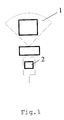
Fig.1 represents a prior art antenna system.
Fig.2 represents another prior art antenna system.
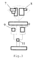
Fig.3 shows an example of an antenna system according
to the present invention.
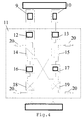
Fig.4 shows an example of a coupler used in an antenna
system according to the present invention.
Fig.5 shows another example of an antenna system
according to the present invention.
Detailed description of the invention
For the purpose of teaching of the invention,
preferred embodiments of the method and system of the
invention are described in the sequel. It will be apparent
to the person skilled in the art that other alternative and
equivalent embodiments of the invention can be conceived
and reduced to practice without departing from the true
spirit of the invention, the scope of the invention being
limited only by the appended claims as finally granted.
The invention combines two or more wide-beam antennas
to generate smaller beams and can be used in any sectorized
wireless network such as, but not limited to, GSM, CDMA,
TDMA, and UMTS. In the simplest case, from a double antenna
system two electrically separated beams, creating two
electrically separated sectors, can be formed, both beams
having the characteristics of the combined antenna.
In Fig.1 a prior art antenna system is shown. The
vertically (90°) placed antenna (2) creates a beam (1) with
a beam-width of 90°.
To create a smaller beam-width two antennas operating
in phase can be coupled as shown in the prior art antenna
system of Fig.2. Two vertically (90°) placed sector
antennas (4,5) operating in phase are coupled via a coupler
(6) to create a beam (3) with half the original beam-width,
i.e. a beam-width of 45°. By doing so the gain is increased
by 3dB, but the antenna system is two times larger compared
to the antenna system of Fig.1.
If two beams with a beam-width of 45° are required,
four antennas are needed according to the prior art.
The invention uses only two antennas to form two small
beams (i.e. two small sectors) at the same time. The
antennas are connected by passive electronic elements, like
couplers and cables. The advantage is that 2 antennas are
saved, while the same effect is achieved.
In Fig.3 an example of an antenna system according to
the present invention is shown. Two beams (7,8), each with
a beam-width of 45°, are created using two sector antennas
(9,10). The two sector antennas can be placed in any
direction. It is e.g. possible to place the antennas at
+45° or at -45° or horizontally at 0° or vertically at 90°.
In this example the two antennas are placed horizontally.
By applying a different phase per antenna the first beam
(7) is shifted -45° and the second beam (8) is shifted
+45°. The coupler (11) enabling this is shown in more
detail in Fig.4.
In Fig.4 two sector antennas (9,10) are coupled via
coupler (11). A different phase is applied per antenna. To
achieve this the first antenna (9) is coupled to the first
receiver pre-amplifier (12) and the second antenna (10) is
coupled to the second receiver pre-amplifier. The hybrid
couplers (14,15,18,19) and the phase shifters (16,17)
create the different phases in which the antennas are
operating. In case the antennas are receiving signals, half
the signaling power is consumed by the resistors (20). The
receiver pre-amplifiers (12,13) compensate the power loss.
In case the antennas are transmitting signals, also half
the signaling power is consumes by the resistors (20). This
can be compensated by increasing the transmitting power by
using X-Pol antennas or using air-combining.
The invention makes it possible to build larger
antenna systems to save more antennas and build very small
sectors. Combining six or more antennas in e.g. a
cylindrical line-up can result in small beams forming
sectors with coverage of up to an angle of 360°. In Fig.5
an example antenna system (21) is shown from above that can
cover an angle of 360°. This antenna system comprises
antennas (22) that are placed in a circle with a diameter
(23). E.g. 36 sectors can be created using the invention,
each sector being covered by an antenna creating a beam
with a beam-width of 10.