EP1498847A2 - Method of obtaining a depth map from a digital image - Google Patents
Method of obtaining a depth map from a digital image Download PDFInfo
- Publication number
- EP1498847A2 EP1498847A2 EP04076850A EP04076850A EP1498847A2 EP 1498847 A2 EP1498847 A2 EP 1498847A2 EP 04076850 A EP04076850 A EP 04076850A EP 04076850 A EP04076850 A EP 04076850A EP 1498847 A2 EP1498847 A2 EP 1498847A2
- Authority
- EP
- European Patent Office
- Prior art keywords
- image
- plane
- case
- depth
- threshold
- Prior art date
- Legal status (The legal status is an assumption and is not a legal conclusion. Google has not performed a legal analysis and makes no representation as to the accuracy of the status listed.)
- Withdrawn
Links
Images


Classifications
-
- G—PHYSICS
- G06—COMPUTING OR CALCULATING; COUNTING
- G06T—IMAGE DATA PROCESSING OR GENERATION, IN GENERAL
- G06T7/00—Image analysis
- G06T7/50—Depth or shape recovery
- G06T7/536—Depth or shape recovery from perspective effects, e.g. by using vanishing points
Definitions
- the present invention relates to the processing of digital images and, more particularly, to a method of obtaining a depth map from a digital image of a three-dimensional scene.
- the relative depths of a pixel is understood as the distance of the point of the three-dimensional scene represented by the pixel from a reference plane that, as a general rule, coincides with the plane of the image.
- the depth map is constituted by a grey-scale image in which each pixel is assigned a value according to its depth. It is usually assumed that the higher the grey-value (lighter grey) associated with a pixel, the nearer is it situated to the reference plane.
- a depth map makes it possible to obtain from the starting image a second image that, together with the starting image, constitutes a stereoscopic pair providing a three-dimensional vision of the scene.
- One object of the present invention is to propose a method that will make it possible to produce a depth map from a single image with short processing times and to a large extent in an automatic manner.
- a particular object of the present invention is to propose a method for obtaining a depth map of a three-dimensional scene containing geometric objects in a completely automatic manner
- Another object is to propose a method of obtaining a depth map from a digital image of any three-dimensional scene, i.e. a landscape scene, or a scene that essentially contains geometric objects, or a scene that contains both a landscape and geometric objects.
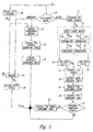
- a digital image 1 of a three-dimensional scene, a colour image for example is analyzed (in a decisional block 10) to determine the category or class to which it belongs.
- This operation may be carried out by an operator on the basis of observing the image or may be carried out in an automatic manner.
- a method of automatically carrying out the operation is described, for example, in an Italian patent application filed by the applicant on the same day as the present application and bears the title "Metodo per class NEED un'immagine digitale", designating the same inventors as are designated in the present application.
- the analysis of the scene may show that the image falls into a category of images substantially devoid of geometric objects, i.e. an image category of "landscapes” or a category of images that contain geometric images, indicated by "Other” in Figure 1.
- image category of "landscapes” or a category of images that contain geometric images indicated by "Other” in Figure 1.
- geometric images is intended to identify objects or structures defined by at least a horizontal plane or at least a vertical plane in the real scene.
- this process comprises the application of an operator, known as the Sobel operator (Block 13), two normalization or scaling operations (Blocks 14) and a threshold segmentation or threshold operation (Block 15).
- the Sobel operator carries out a measurement of the two-dimensional space gradient to highlight the regions of a high spatial frequency that correspond to the outlines of the objects in the image.
- I Sx I * S x
- I Sy I * S y
- Each Block 16 is constituted by a low-pass filter that operates by means of the application of the convolution of a Mask A of size 5x5 with appropriate coefficients. It is used to eliminate possible disturbance peaks present in I Sx and I Sy .
- Blocks 15 and 16 are applied to a straight-line-search block 17 that carries out a series of operations based on a procedure known as the Hough transform.
- the Hough transform makes it possible to identify various geometric configurations, like lines, circumferences or any curve that can be represented in parametric form, but in the present application it is used to identify only straight lines.
- r and ⁇ defines a point in a parameter space or Hough space. Each point of this space therefore identifies a straight line of the Cartesian plane x,y.
- the check consists of observing for each pixel how many pixels in a predetermined surrounding area belong to the straight line that has just been found (it should be remembered that to verify whether or not a point belongs to a given straight line one substitutes the coordinates of the point in the equation of the straight line and observes whether equality is effectively obtained). If this number is greater than a predetermined threshold value, the consistency check is successful and the pair (m,q) can at last be memorized in the accumulation matrix.
- the phase of memorizing the pair (m,q) envisages first the quantization of these two values and then the updating of the corresponding value of the accumulation matrix ACC.
- m there has been conceived a scale of values subdivided with an irregular interval. This interval becomes gradually smaller as zero is approached and becomes larger when one moves away from zero. All this in order to have greater detail in the range of values of m comprised between -1 and 1, where a minute variation implies straight lines with widely different slopes. To resolve the problem of the greatly inclined straights, which are associated with a large angular coefficient, these are represented by a value of m equal to ⁇ 8, having verified that these values well approximate these slopes.
- the value scale of q is obtained with a regular interval.
- the N straights obtained are candidates for becoming the looked for vanishing lines. This fact derives from having noted that in an image with marked geometric characteristic the vanishing lines are the lines that occur most frequently, because they coincide with the greater part of the outlines of the objects present in the image..
- a statistical approach is adopted for finding the vanishing point.
- the idea is that the candidate vanishing lines intersect with greater frequency in the zone containing the vanishing point.
- the looked-for vanishing point will be the point having the largest number of "neighbours", that is to say, it will coincide with the accumulation point of the entire image.
- the next operation is the search for the vanishing lines (Block 20).
- each of these straights is chosen as a vanishing line if, together with another straight, it had previously generated an intersection point falling within the neighbourhood of the vanishing point. In case the straight in question has not generated any intersections "near" the vanishing point it will be discarded. In the light of these considerations, one can affirm that the number of vanishing lines may vary between a minimum value equal to 2 and a maximum value equal to N.
- the position of the found vanishing point is examined (Block 21) to verify whether it is situated outside or inside a central image zone of predetermined dimensions. If it is situated outside, one passes directly to the successive phase of assigning depth levels, otherwise one performs an intermediate search operation of searching for other vanishing lines (Block 22). This operation is necessary in order to render possible a correct identification of the planes present in the image in this particular position of the vanishing point, as will be explained later on. In particular, for every contemplated angular coefficient there is calculated the ordinate at the origin of the straight that has this angular coefficient and passes through the vanishing point.
- the accumulation matrix ACC of the parameters is analyzed, checking whether the pair (m,q) in question had been found previously in the search for straight lines of Block 17. If the check yields a positive result, the straight identified by the present pair of parameters is added to the set of vanishing lines.
- the information I vld (x,y) relating to the vanishing point and the vanishing lines is utilized for assigning a depth level to each pixel of the image, thereby obtaining a depth map of the starting image I(x,y). Similar information I vld (x,y) may be generated also in the case in which the analysis of the image carried out in Block 10 leads to the conclusion that the image belongs to the "Landscape" category. In that case there is identified a vanishing point, i.e. a central point of the image that is situated on the line of the horizon, and there is identified the plane passing through the line of the horizon in which there are drawn two fictitious vanishing lines that intersect at the central vanishing point.
- the starting image is subdivided into a multiplicity of homogeneous regions, associating each pixel with a region on the basis of at least one of the digital values of the given pixel, for example on the basis of its chromatic characteristics (Block 30).
- the regions are: "Sky”, “very distant mountain”, “Distant mountain”, “Nearby mountain”, “land” and "other”.
- each region is labelled with a predetermined grey value and, more precisely, in such a manner that the regions closest to the observer (image plane) are labelled with a clearer grey level than that of the more distant regions.
- This partial map, indicated by M2 constitutes the output of Block 30, the one that subdivides into regions, and an input for a Block 31, and a Block 35.
- Block 31 identifies the region adjacent to the union between the region "Land” and the region "Other”. This information will be exploited in Block 34 to establish which is to be the lowest grey level to be used in the depth gradient. For example, in the case in which the adjacent region is "Sky”, this is identified by a grey level equal to 0. In that case a gradient up to a grey level equal to 32 will be drawn in Block 34, while in the case of "Nearby mountain” the lowest grey level will be 100.
- the central vanishing point is identified in Block 32.
- the following criterion is adopted to this end:
- Two vanishing lines intersecting at the vanishing point and having predetermined angular coefficients are created in Block 33.
- the information relating to the vanishing point and the fictitious vanishing lines are applied as input to a Block 34 for assigning depth levels.
- the assignment process commences with the analysis of the position of the vanishing point with respect to the image. In particular, starting from its coordinates, the analysis seeks to ascertain which of the following conditions is satisfied:
- the lines are classified into 4 classes by means of the following parameters:
- the first parameter which represents the intersection point of the vanishing line with the border of the image, indicates whether the origin of the vanishing line is situated in a position of which the coordinate Y o is smaller or greater than the coordinate Y vp of the vanishing point.
- Figures 4 and 5 illustrate, respectively, a possible Left Case situation and a Right Case situation.
- the vanishing lines can belong only to Classes 1 and 4 in the Left Case and only to Classes 2 and 3 in the Right Case.
- the lines are ordered according to growing values of the angular coefficient and two lines are selected from among them in such a manner that:
- a third vanishing line is also identified in such a manner that:
- the angular coefficients m1, m2, m3 are analyzed for the generation of these planes and the planes (horizontal or vertical planes or both) are obtained on the basis of their values.
- Figures 6 and 7 illustrate, respectively, a possible situation of the Up Case and another of the Down Case.
- the vanishing lines can belong only to Classes 3 and 4 in the Up Case and only to Classes 1 and 2 in the Down Case.
- the lines are subdivided into:
- a third vanishing line is also identified in such a manner that:
- Figure 8 illustrates a possible situation in which the vanishing point is in a central zone of the image (Inside Case).
- the vanishing lines can belong to all the classes.
- the next step consists of subdividing the vanishing lines into: Class 1, Class 2, Class 3 and Class 4 .
- a grey level corresponding to a depth level is assigned to each pixel of the gradient planes.
- the assignment is made for rows in the horizontal gradient planes and for columns in the vertical planes with the depth level increasing in the direction of the vanishing point, starting from a line of the image that is, respectively, horizontal or vertical, in this example one of the border lines of the image.
- the law of assigning the depth is approximated by a curve that is sectionally linear and depends on the values of the angular coefficients m1 and m2 of the straights that generate the plane.
- D min q2/m2-q1/m1
- D max (H-1-q1) /m1- (H-1-q2) /m2;
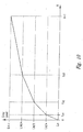
- Figure 10 shows a qualitative graph of the sectionally linear curve relating to the case of Figure 9; the ordinates represent the grey value assigned to each row Y i of the image.
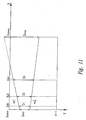
- D min q1-q2
- D max (m2-m1) (W-1)+q2-q1;
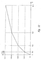
- Figure 12 shows a qualitative graph of the sectionally linear curve relating to the case of Figure 11; the ordinates represent the grey value assigned to every column X i of the image.
- Block 35 represents the last operation of the method in accordance with the invention. It receives as input M 1 (x,y) and M 2 (x,y) to generate the final depth map M(x,y) as output. It should be noted that M 1 (x,y) can be a partial depth map generated for an image classified as “Landscape” or as "Other”.
- region region cardinality region region cardinality .... . 1 2 10.1.
- region indicates whether the type of region identified during the scanning is "Sky” or "Non-sky” and the region cardinality indicates the number of consecutive pixels forming part of the region.
- Non-sky represents any one of the regions defined above, though with the obvious exception of the region "Sky”.
- the structure is dynamic: a new element is added every time that a new region is identified during the scanning of the column.
- threshold _1 0.01
- threshold _2 0.05
- the depth map obtained by means of the method described above is derived from a single image and therefore from a set of starting data that is reduced as compared with the techniques that call for the analysis of several images, has a lower resolution than the resolution of the starting image, can be greatly compressed, enjoys perfect two-dimensional compatibility and makes it possible to generate stereoscopic pairs in real time. It can be obtained in a completely automatic manner when the choice of the category to which the image belongs is made in accordance with the cited patent application filed on the same day as the present application or in a partially automatic manner if the choice of category calls for the intervention of an operator.
- the method in accordance with the invention may be put into practice with many variants with respect to the example described hereinabove.
- it can be applied in such a manner as to find several vanishing points in order to obtain a more detailed depth map, especially when the map is to be used for converting two-dimensional images into three-dimensional images.
Landscapes
- Engineering & Computer Science (AREA)
- Computer Vision & Pattern Recognition (AREA)
- Physics & Mathematics (AREA)
- General Physics & Mathematics (AREA)
- Theoretical Computer Science (AREA)
- Image Analysis (AREA)
- Length Measuring Devices By Optical Means (AREA)
- Image Processing (AREA)
Abstract
Description
- Figure 1 is a block diagramme of an embodiment of a method in accordance with the invention and
- Figures 2 to 12 are graphs that illustrate various phases of the method in accordance with the invention.


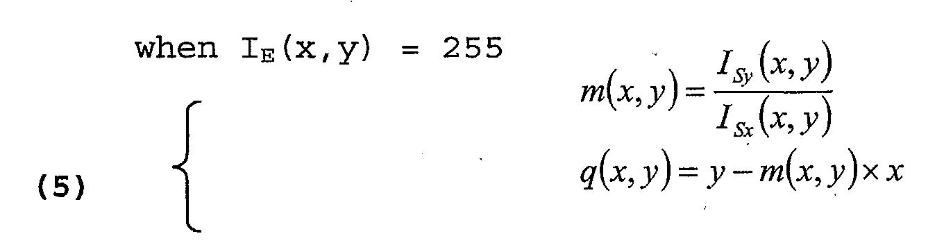

∀m
q = yvp - m×xvp
if ACC[m', q'] ≠ 0
thenadd (m', q')tothesetofvanishing_lines
having used (xvp, yvp) to indicate the coordinates of the vanishing point and (m',q') to indicate the approximate values of the parameters.
- there is acquired the sequence of regions
starting from below:
- if the first region is "Other" and its length is greater than a value temp_max (initially put as zero), then temp_max = length of first region;
- Xvp<=0 AND (H-1/W-1)*Xvp<Yvp<-(H-1/W-1)*Xvp+H-1
- Xvp>=W-1 AND (H-1/W-1) *Xvp+H-1<Yvp< (H-1/W-1)*Xvp
- Yvp<=0 AND (W-1/H-1)*Yvp <=Xvp<=(W-1/H-1)* (H-1-YvP)
- Yvp>=H-1 AND (W-1/H-1) * (H-1-Yvp)<=Xvp<=(W-1/H-1)*Yvp
- 0<Xvp<W-1 AND 0<Yvp<H-1
where Xvp and Yvp indicate the coordinates of the vanishing point on the plane of the image and H (Height) and W (Width) indicate the dimensions of the input image.
- the number of vanishing lines identified must be >=2.
- origin, in the image, of the vanishing line relative to the position of the vanishing point
- sign of the angular coefficient of the vanishing line.
- m1= min among the angular coefficients
- m3= max among the angular coefficients
- m1= max among the angular coefficients
- m3= min among the angular coefficients
- m2>= threshold_m2
- m2<=-threshold_m2
- num_lines=2.
- num_lines=3.
- if m1>=threshold_m1 (Left Case) or if m1<=-threshold_m1 (Right Case) ⇒ there is generated a horizontal gradient plane defined by the two straights with angular coefficients m1 and m3 and in it there will be drawn a depth gradient depending on the said two straights;
- if m1<threshold_m1 AND m3>threshold_m3 AND m2>=threshold_m2, (Left Case) or if m1>-threshold_m1 AND m3<-threshold_m3 AND m2<=-threshold_m2 (Right Case) ⇒ there is generated a horizontal plane and a vertical plane and in them there is drawn a depth gradient depending on the said two straights having angular coefficients of, respectively, m2 and m3 or m1 and m2. This choice is made on the basis of geometric considerations and for the purpose of not leaving the gradient incomplete in one of the two planes. The straight with the angular coefficient m2 is the "border" between the two gradient planes;
- if m1<threshold_m1 AND m3>threshold_ m3 AND num_lines=2 (Left Case) or if m1>-threshold_m1 AND m3<-threshold_m3 AND num_lines=2 (Right Case) ⇒ there is generated a vertical gradient plane and in it there is drawn a depth gradient depending on the two straights having depth gradients of, respectively, m1 and m3;
- Value of the angular coefficient m1.
- Value of the angular coefficient m3.
- if there has been generated a horizontal gradient plane with m1<threshold_deduction_m1 (Left Case) or m1>-threshold_deduction_m1 (Right Case) ⇒ there is generated a further vertical gradient plane with the same depth gradient as the horizontal one; the straight with the angular coefficient m1 is the "border" between the two planes;
- if there has been generated a vertical gradient plane with m3>=threshold_deduction_m3 (Left Case) or m3<=-threshold_deduction_m3 (Right Case) ⇒ there is generated a further horizontal gradient plane with the same depth gradient as the vertical one; the straight with angular coefficient m1 is the "border" between the two planes;
- Class 3
- Class 4
- Class 1
- Class 2
- m1_3 = max between the angular coefficients of the vanishing lines of Class 3.
- m3_3 = min between the angular coefficients of the vanishing lines of Class 3.
- m1_4 = min between the angular coefficients of the vanishing lines of Class 4.
- m3_4 = max between the angular coefficients of the vanishing lines of Class 4.
- m1_1 = max between the angular coefficients of the vanishing lines of Class 1.
- m3_1= min between the angular coefficients of the vanishing lines of Class 1.
- m1_2 = min between the angular coefficients of the vanishing lines of Class 2.
- m3_2 = max between the angular coefficients of the vanishing lines of Class 2.
- m2 _ 3<=threshold_m2_3
- m2 _ 4>=threshold_m2_4
if -q1_3/m1_3>=W-1 AND -q3_3/m3_3>=W-1 ⇒ threshold_m2_3 = predetermined value chosen between -0.05 and -0.04, for example -0.2;
otherwise ⇒ threshold_m2_3 = predetermined value chosen between -0.7 and -1.3, for example -1;
if -q1_4/m1_4<=0 AND -q3_4/m3_4<=0 ⇒ threshold _m2_4 = predetermined value chosen between 0.05 and 0.4, for example 0.2;
otherwise ⇒ threshold_m2_4 = predetermined value chosen between 0.7 and 1.3, for example 1;
and q(num)_(class) is the notation used to indicate the ordinate at the origin of a straight.
- m2_1<=threshold_m2_1
- m2_2>=threshold_m2_2
if H-1-q1_1/m1_1<=0 AND H-1-q3_1/m3_1<=0 ⇒ threshold m2_1 = predetermined value chosen between -0.05 and -0.4, for example -0.2;
otherwise ⇒ threshold_m2_1 = predetermined value chosen between -0.7 and -1.3, for example -1;
if H-1-q1_2/m1_2>=W-1 AND H-1-q3_2/m3_2>=W-1⇒ threshold_m2_2 = predetermined value chosen between 0.05 and 0.4, for example 0.2;
otherwise ⇒ threshold_m2_2 = predetermined value chosen between 0.7 and 1.3, for example 1
and q(num)_(class) is the notation used to indicate the ordinate at the origin of a straight.
- num_lines_class=2
- num_lines_class=3
- if m1_3<=threshold_m1_3 (Up Case) or if m1_1<=threshold_m1_1 (Down Case) ⇒ there is generated a horizontal gradient plane and in it there will be drawn a depth gradient depending on the two straights having an angular coefficient of, respectively, m1_3 and m3_3 (Up Case) or m1_1 and m3_1 (Down Case);
- if m3_3>=threshold_m3_3 (Up Case) or if m3_1>=threshold_m3_1 (Down Case) ⇒ there is generated a vertical gradient plane and in it there will be drawn a depth gradient depending on the two straights having an angular coefficient of, respectively, m1_3 and m3_3 (Up Case) or m1_1 and m3_1 (Down Case);
- if m1_3>threshold_m1_3 AND m3_3<threshold_m3_3 AND m2_3<=threshold_m2_3 (Up Case) or if m1_1>threshold_m1_1 AND m3_1 <threshold_m3_1 AND m2_1 <=threshold_m2_1 (Down Case) ⇒ there is generated a horizontal plane and a vertical plane and in them there will be drawn a depth gradient depending on the two straights having an angular coefficient of, respectively, m2_3 and m3_3 or m1_3 and m2_3 (Up Case) or, respectively, m2_1 and m3_1 or m1_1 and m2_1 (Down Case); this choice is made on the basis of geometric considerations and for the purpose of not leaving the gradient incomplete in one of the two planes; the straight with angular coefficient m2_3 (Up Case) or m2_1 (Down Case) is the "border" between the two gradient planes;
- if m1_3 >threshold_m1_3 AND m3_3<threshold_m3_3 AND num_lines_3=2 (Up Case) or if m1_1>threshold_m1_1 AND m3_1<threshold_m3_1 AND num_lines_1=2 (Down Case) ⇒ there is generated a vertical gradient plane and in it there will be drawn a depth gradient depending on the two straights having an angular coefficient of, respectively, m1_3 and m3_3 (Up Case) or m1_1 and m3_1 (Down Case) ;
- if m1_4>=threshold_m1_4 (Up Case) or if m1_2>=threshold_m1_2 (Down Case) ⇒ there is generated a horizontal gradient plane and in it there will be drawn a depth gradient depending on the two straights having an angular coefficient of, respectively, m1_4 and m3_4 (Up Case) or m1_2 and m3_2 (Down Case);
- if m3_4<=threshold_m3_4 (Up Case) or if m3_2<=threshold_m3_2 (Down Case)⇒ there is generated a vertical gradient plane and in it there will be drawn a depth gradient depending on the two straights having an angular coefficient of, respectively, m1_4 and m3_4 (Up Case) or m1_2 and m3_2 (Down Case);
- se m1_4<threshold_m1_4 AND m3_ 4>threshold_m3_4 AND m2_4 >=threshold_m2_4 (Up Case) or if m1_2<threshold_m1_2 AND m3_2>threshold_m3_2 AND m2_2>=threshold_m2_2 (Down Case) ⇒ there is generated a horizontal plane and a vertical plane and in them there will be drawn a depth gradient depending on the two straights having an angular coefficient of, respectively, m2_4 and m3_4 or m1_4 and m2_4 (Up Case) or, respectively, m2_2 and m3_2 or m1_2 and m2_2 (Down Case). This choice is made on the basis of geometric considerations and for the purpose of not leaving the gradient incomplete in one of the two planes; the straight with angular coefficient m2_4 (Up Case) or m2_2 (Down Case) is the "border" between the two gradient planes;
- if m1_4<threshold_m1_4 AND m3_4>threshold_m3_4 AND num_lines_4=2 (Up Case) or if m1 _ 2<threshold_m1_2 AND m3 _ 2 >threshold_m3_2 AND num_lines_2=2 (Down Case) ⇒ there is generated a vertical gradient plane and in it there will be drawn a depth gradient depending on the two straights having an angular coefficient of, respectively, m1_4 and m3_4 (Up Case) or m1_2 and m3_2 (Down Case);
- Up Case:
if -q1_3/m1_3>=W-1 AND -q3_3/m3_3>=W-1 ⇒ threshold_m1_3 = threshold_m3_3 = predetermined value chosen between 0.05 and -0.5, for example -0.3;
otherwise ⇒ threshold_m1_3 = threshold_m3_3 = predetermined value between -0.7 and -1.3, for example - 1;
if -q1_4/m1_4<=0 AND -q3_4/m3_4<=0 ⇒ threshold_m1_4 = threshold_m3_4 = predetermined value chosen between 0.05 and 0.5, for example 0.3;
otherwise ⇒ threshold_m1_4 = threshold_m3_4 = predetermined value chosen between 0.7 and 1.3, for example 1;
and q(num)_(class) is the notation used to indicate the ordinate at the origin of a straight. - Down Case:
if H-1-q1_1/m1_1<=0 AND
H-1-q3_1/m3_1<=0 ⇒ threshold_m1_1 = threshold_m3_1 = predetermined value chosen between -0.05 and -0.5, for example -0.3;
otherwise ⇒ threshold_m1_1 = threshold_m3_1 = predetermined value chosen between -0.7 and -1.3, for example -1;
if H-1-q1_2/m1_2>=W-1 AND
H-1-q3_2/m3_2>=W-1
⇒threshold_m1_2=threshold_m3_2 = predetermined value chosen between 0.05 and 0.5, per example 0.3
otherwise ⇒ threshold_m1_2 = threshold_m3_2 = predetermined value chosen between 0.7 and 1.3, for example 1;
and q(num)_(class) is the notation used to indicate the ordinate at the origin of a straight.
- Value of the angular coefficient m1_3.
- Value of the angular coefficient m3_3.
- Value of the angular coefficient m1_4.
- Value of the angular coefficient m3_4.
- Value of the angular coefficient m1_1.
- Value of the angular coefficient m3_1.
- Value of the angular coefficient m1_2.
- Value of the angular coefficient m3_2.
- if there has been generated a horizontal gradient plane with m1_3>=threshold_deduction_m1_3 (Up Case) or m1_1>=threshold_deduction m1_1 (Down Case) ⇒ there is generated a further vertical gradient plane with the same depth gradient as the horizontal plane; the straight with the angular coefficient m1_3 (Up Case) or m1_1 (Down Case) is the "border" between the two planes;
- if there has been generated a vertical gradient plane with m3_3 <=threshold deduction m3_3 (Up Case) or m3_1<=threshold_deduction_m3_1 (Down Case) ⇒ there is generated a further horizontal gradient plane with the same depth gradient as the vertical plane; the straight with the angular coefficient m3_3 (Up Case) or m3_1 (Down Case) is the "border" between the two planes;
- if there has been generated a horizontal gradient plane with m1_4<=threshold deduction_m1_4 (Up Case) or m1_2<=threshold deduction_m1_2 (Down Case) ⇒ there is generated a further vertical gradient plane with the same depth gradient as the horizontal plane; the straight with the angular coefficient m1_4 (Up Case) or m1_2 (Down Case) is the "border" between the two planes;
- if there has been generated a vertical gradient plane with m3_4>=threshold deduction_m3_4 (Up Case) or m3_2>=threshold deduction m3 2 (Down Case) ⇒ there is generated a further horizontal gradient plane with the same depth gradient as the vertical plane; the straight with the angular coefficient m3_4 (Up Case) or m3_2 (Down Case) is the "border" between the two planes;
- Up Case:
threshold_deduction_m1_3 = threshold_deduction_m3_3 = predetermined value chosen between -1.7 and -1.3, for example -1.5;
threshold_deduction_m1_4 = threshold_deduction m3_4= predetermined value chosen between 1.7 and 1.3, for example 1.5. - Down Case:
threshold_deduction_m1_1 = threshold_deduction_m3_1 = predetermined value chosen between -1.7 and -1.3, for example -1.5;
threshold_deduction_m1_2 = threshold_deduction_m3_2 = predetermined value chosen between 1.7 and 1.3, for example 1.5.
- Yvp = mi * Xvp + qi ⇒ qi = Yvp - mi * Xvp
- The higher (lighter) the grey level assigned to a pixel, the "closer" is it situated to the observer.
- The closer one comes to the vanishing point, the further one moves away from the observer (this is almost always true).
- Y0 =0 YH=H-1 in Left Case, Right Case, Up Case and Down Case;
- Y0 =0 YH=Yvp in Inside Case with vanishing lines of Class 1 or Class 2;
- between Dmax and D3 ⇒ 0<=x<=W-1 AND Yd3 <=y<= Ydmax;
- between D3 and D2; ⇒ 0<=x<=W-1 AND Yd2 <=y<= Yd3;
- between D2 and D1; ⇒ 0<=x<=W-1 AND Yd1 <=y<= Yd2 ;
- between D1 and Dmin. ⇒ 0<=x<=W-1 AND Ydmin <=y<= Yd1 ;
- X0 =0 Xw =W-1 in Left Case, Right Case, Up Case and Down Case;
- X0 =0 Xw=Xvp in Inside Case with vanishing lines of Class 2 or Class 3;
- X0 =Xvp Xw =W-1 in Inside Case with vanishing lines of Class 1 or Class 4.
- between Dmax and D3 ⇒ 0<=y<=H-1 AND Xd3 <=x<= Xdmax;
- between D3 and D2 ; ⇒ 0<=y<=H-1 AND Xd2 <=x<= Xd3 ;
- between D2 and D1 ; ⇒ 0<=y<=H-1 AND Xd1 <=X<= Xd2 ;
- between D1 and Dmin. ⇒ 0 <=y<=H-1 AND Xdmin <=x<= Xd1 ;
- an object photographed from two different distances will occupy on the plane of the image a different pixel portion in each of the two cases; in particular, the further the observer is removed from the object, the "smaller" will this object appear: therefore, if the same grey level variation is to be maintained in it, given that the relative depth does not change, the gradient is characterized by an increment of depth levels that becomes gradually greater as the vanishing point is approached;
- the human eye succeeds more readily in distinguishing two nearby and high /(light) grey levels than two nearby and low /(dark) grey levels: it is therefore preferable to have the greatest variations in the darker areas
- if the image belongs to the internal
category, then M(x,y) coincides with M1(x,y):
M(x,y)=M1(x,y) for ∀x,y : 0<=x<=W-1 0<=y<=H-1. - If the image belongs to the external category with absence of significant geometric components (landscapes), then the image M(x,y) is obtained by modifying in the image M2(x,y) the grey values of the pixels belonging to the regions "Land" and "Other".
- If the image belongs to the external
category with geometric components, then the image
M(x,y) is obtained by overwriting the grey values
of the pixels that in the image M2(x,y) form part
of the sky region in the corresponding pixels in
the image M1(x,y). The overwriting is in reality
preceded by a phase "verifying the consistency" of
the regions that is carried out on the basis of the
dimensions and the positions that they occupy
between them:
- 1. M2 (x, y) = M2c (x, y) ;
- 2. M(x,y)= M2(x,y) for ∀ (x,y) ∈ sky ; M(x,y)= M1(x,y) for ∀(x, y) ∉ sky .
M2c (x,y) represents the image M2(x,y) after it has been subjected to the "consistency verification".
| region | region cardinality | region | region cardinality | .... | ..... |
| 1 | 2 | ...................... |

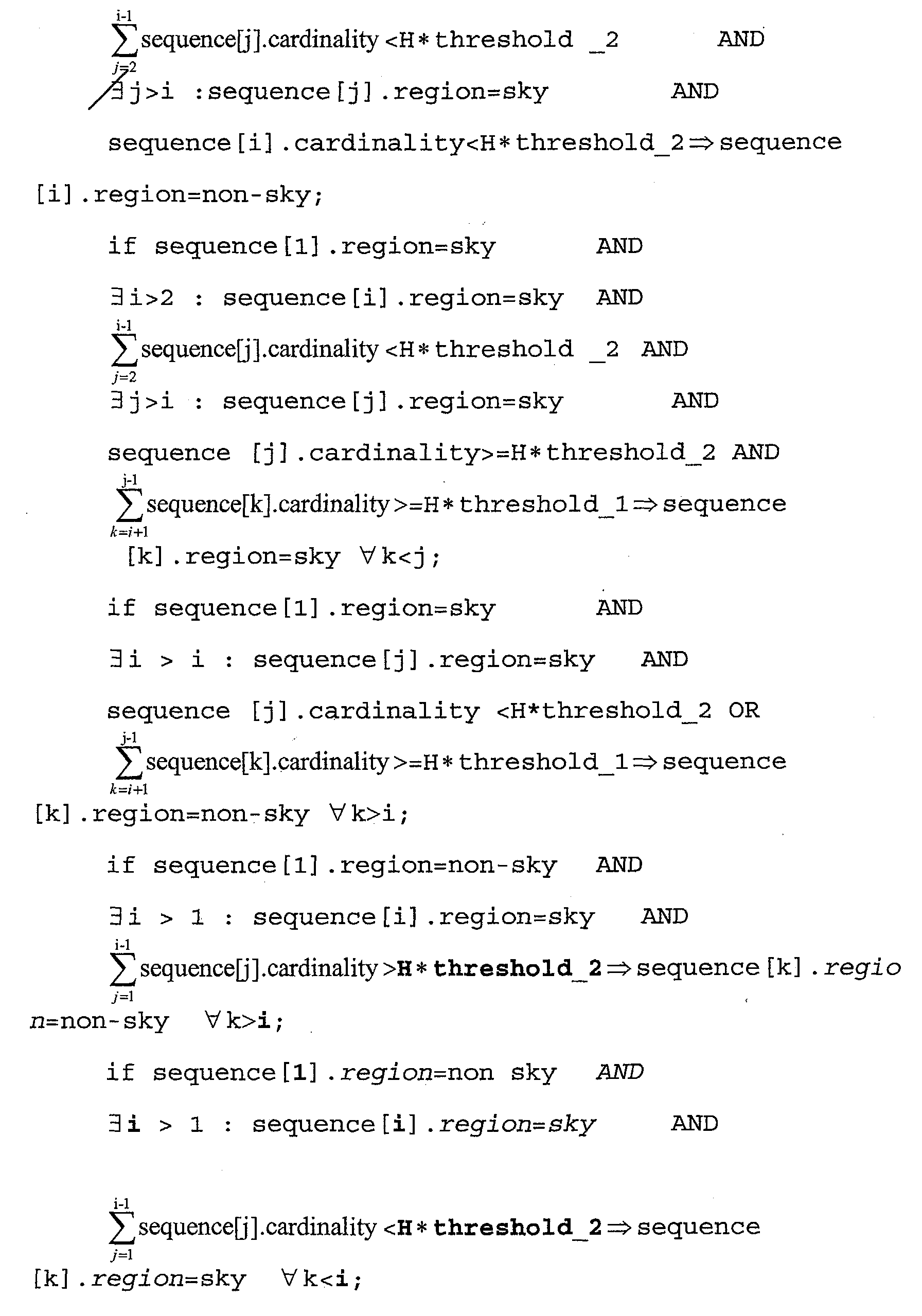


threshold _1=0.01;
threshold _2=0.05;
therefore, a sequence is generated for every column of the image M2(x,y); as was seen above, the modification of the sequence causes an updating of the image M2(x,y) in M2c(x,y).
Claims (7)
- A method of obtaining a depth map from a digital image of a three-dimensional scene containing geometric objects
characterized by the following steps:identifying in the image at least one horizontal plane or one vertical plane of the three-dimensional scene andassigning to each point of the image belonging to the identified plane, or to each of the identified planes, a depth level according to its distance from, respectively, a predetermined horizontal or vertical reference straight of the image. - A method in accordance with Claim 1, wherein the identification of at least one plane comprises the identification in the image of at least two vanishing lines corresponding to two parallel lines in the plane.
- A method in accordance with Claim 2, wherein the assigned depth level is a function of the angular coefficients of the identified vanishing lines.
- A method in accordance with Claim 2 or Claim 3, wherein the identification of at least two vanishing lines comprises the following steps:identifying in the image the outline of at least one geometric object of the three-dimensional scene,identifying a multiplicity of straight lines passing through points of the outline,identifying in this multiplicity a predetermined number of straight lines and choosing from among them those that occur most frequently,selecting from among said predetermined number of straight lines at least two straight lines that intersect each other in a point, assuming them to be the identified vanishing lines.
- A method in accordance with any one of Claims 2 to 4, wherein the identification of at least one plane comprises the following steps:identifying among the identified vanishing lines the vanishing line with the greatest angular coefficient and the vanishing line with the smallest angular coefficient,predetermining threshold values for the greatest and smallest angular coefficients, andconsidering the identified plane as horizontal plane or as vertical plane on the basis of a comparison of the angular coefficients of the vanishing lines with the greatest and smallest angular coefficient and the relative predetermined threshold values.
- A method in accordance with Claim 5, wherein the step of predetermining the threshold values of the greatest and smallest angular coefficients is based on heuristic criteria.
- A method of obtaining a depth map from a digital image of a three-dimensional scene characterized by the following steps:subdividing the image into a multiplicity of homogeneous regions, associating each point of the image with a region on the basis of its chromatic characteristics,defining a multiplicity of image categories, including a first category of images containing predominantly geometric objects (interiors), a second category of images substantially devoid of geometric objects (landscapes) and a third category of images containing geometric objects (landscapes with geometric objects),identifying the category to which the image belongs,if the image belongs to the first or the third category, putting into practice the method in accordance with any one of Claims 1 to 6 in order to obtain a first partial depth map (M1),if the image belongs to the second category (landscapes) :assigning to every point of the image a depth level in accordance with the region to which it belongs in order to form a second partial depth map (M2),identifying a horizon line in the image,identifying the plane passing through the horizon line, andassigning to every point of the image belonging to the identified plane a depth level according to its distance from a predetermined horizontal reference line of the image in order to form a third partial depth map (M1),obtaining the depth map from the three partial maps by means of the following criterion:if the image belongs to the first category interiors), assuming the first partial map (M1) as the depth map of the image,if the image belongs to the second category (landscapes), merging the second (M2) and the third (M1) partial depth maps substituting the depth values of the second map associated with points belonging to at least one predetermined region with the homogeneous regions for the corresponding depth values, as far as position in the image is concerned, of the third map,if the image belongs to the third category (landscapes with geometric objects), merging the first (M1) and the second (M2) partial maps, substituting the depth values of the second map (partial M2) associated with points belonging to at least one predetermined region of the homogeneous regions with the corresponding depth values of the first partial map (M1), after having verified the consistency by examining the regions to which there belong the points of a predetermined neighbourhood around the point in question.
Applications Claiming Priority (2)
| Application Number | Priority Date | Filing Date | Title |
|---|---|---|---|
| ITRM20030345 | 2003-07-15 | ||
| IT000345A ITRM20030345A1 (en) | 2003-07-15 | 2003-07-15 | METHOD TO FIND A DEPTH MAP |
Publications (2)
| Publication Number | Publication Date |
|---|---|
| EP1498847A2 true EP1498847A2 (en) | 2005-01-19 |
| EP1498847A3 EP1498847A3 (en) | 2006-02-15 |
Family
ID=29765915
Family Applications (1)
| Application Number | Title | Priority Date | Filing Date |
|---|---|---|---|
| EP04076850A Withdrawn EP1498847A3 (en) | 2003-07-15 | 2004-06-25 | Method of obtaining a depth map from a digital image |
Country Status (3)
| Country | Link |
|---|---|
| US (1) | US7668377B2 (en) |
| EP (1) | EP1498847A3 (en) |
| IT (1) | ITRM20030345A1 (en) |
Cited By (5)
| Publication number | Priority date | Publication date | Assignee | Title |
|---|---|---|---|---|
| EP2194504A1 (en) * | 2008-12-02 | 2010-06-09 | Koninklijke Philips Electronics N.V. | Generation of a depth map |
| CN101751664B (en) * | 2008-12-02 | 2013-04-17 | 奇景光电股份有限公司 | Stereo Depth Information Generation System and Method |
| US8638986B2 (en) | 2011-04-20 | 2014-01-28 | Qualcomm Incorporated | Online reference patch generation and pose estimation for augmented reality |
| ITVI20120303A1 (en) * | 2012-11-09 | 2014-05-10 | St Microelectronics Srl | METHOD TO DETECT A STRAIGHT LINE IN A DIGITAL IMAGE |
| US9224205B2 (en) | 2012-06-14 | 2015-12-29 | Qualcomm Incorporated | Accelerated geometric shape detection and accurate pose tracking |
Families Citing this family (32)
| Publication number | Priority date | Publication date | Assignee | Title |
|---|---|---|---|---|
| WO2006137000A1 (en) * | 2005-06-23 | 2006-12-28 | Koninklijke Philips Electronics N.V. | Combined exchange of image and related data |
| KR100873638B1 (en) * | 2007-01-16 | 2008-12-12 | 삼성전자주식회사 | Image processing method and device |
| KR101388133B1 (en) * | 2007-02-16 | 2014-04-23 | 삼성전자주식회사 | Method and apparatus for creating a 3D model from 2D photograph image |
| US8213711B2 (en) * | 2007-04-03 | 2012-07-03 | Her Majesty The Queen In Right Of Canada As Represented By The Minister Of Industry, Through The Communications Research Centre Canada | Method and graphical user interface for modifying depth maps |
| CA2627999C (en) * | 2007-04-03 | 2011-11-15 | Her Majesty The Queen In Right Of Canada, As Represented By The Minister Of Industry Through The Communications Research Centre Canada | Generation of a depth map from a monoscopic color image for rendering stereoscopic still and video images |
| KR100918862B1 (en) * | 2007-10-19 | 2009-09-28 | 광주과학기술원 | Method and device for generating depth image using reference image, and method for encoding or decoding the said depth image, and encoder or decoder for the same, and the recording media storing the image generating the said method |
| US8508550B1 (en) * | 2008-06-10 | 2013-08-13 | Pixar | Selective rendering of objects |
| KR20100002032A (en) * | 2008-06-24 | 2010-01-06 | 삼성전자주식회사 | Image generating method, image processing method, and apparatus thereof |
| WO2009157713A2 (en) * | 2008-06-24 | 2009-12-30 | Samsung Electronics Co., Ltd. | Image processing method and apparatus |
| US20090315980A1 (en) * | 2008-06-24 | 2009-12-24 | Samsung Electronics Co., | Image processing method and apparatus |
| WO2009157707A2 (en) * | 2008-06-24 | 2009-12-30 | Samsung Electronics Co,. Ltd. | Image processing method and apparatus |
| WO2010085186A1 (en) * | 2009-01-21 | 2010-07-29 | Telefonaktiebolaget L M Ericsson (Publ) | Generation of annotation tags based on multimodal metadata and structured semantic descriptors |
| JP5541914B2 (en) * | 2009-12-28 | 2014-07-09 | オリンパス株式会社 | Image processing apparatus, electronic apparatus, program, and operation method of endoscope apparatus |
| WO2011097306A1 (en) * | 2010-02-04 | 2011-08-11 | Sony Corporation | 2d to 3d image conversion based on image content |
| US9053562B1 (en) | 2010-06-24 | 2015-06-09 | Gregory S. Rabin | Two dimensional to three dimensional moving image converter |
| US8848038B2 (en) * | 2010-07-09 | 2014-09-30 | Lg Electronics Inc. | Method and device for converting 3D images |
| US8571314B2 (en) | 2010-09-02 | 2013-10-29 | Samsung Electronics Co., Ltd. | Three-dimensional display system with depth map mechanism and method of operation thereof |
| KR101638919B1 (en) * | 2010-09-08 | 2016-07-12 | 엘지전자 주식회사 | Mobile terminal and method for controlling the same |
| TW201220253A (en) * | 2010-11-15 | 2012-05-16 | Inst Information Industry | Image calculation method and apparatus |
| US8824821B2 (en) | 2011-03-28 | 2014-09-02 | Sony Corporation | Method and apparatus for performing user inspired visual effects rendering on an image |
| TWI481262B (en) | 2011-07-28 | 2015-04-11 | Ind Tech Res Inst | Image encoding system and image encoding method |
| KR101862543B1 (en) | 2011-09-08 | 2018-07-06 | 삼성전자 주식회사 | Apparatus, meethod for generating depth information and computer-readable storage medium thereof |
| US9471988B2 (en) * | 2011-11-02 | 2016-10-18 | Google Inc. | Depth-map generation for an input image using an example approximate depth-map associated with an example similar image |
| US9661307B1 (en) | 2011-11-15 | 2017-05-23 | Google Inc. | Depth map generation using motion cues for conversion of monoscopic visual content to stereoscopic 3D |
| US8897542B2 (en) * | 2011-12-15 | 2014-11-25 | Sony Corporation | Depth map generation based on soft classification |
| US9571810B2 (en) | 2011-12-23 | 2017-02-14 | Mediatek Inc. | Method and apparatus of determining perspective model for depth map generation by utilizing region-based analysis and/or temporal smoothing |
| US9111350B1 (en) | 2012-02-10 | 2015-08-18 | Google Inc. | Conversion of monoscopic visual content to stereoscopic 3D |
| US8644596B1 (en) | 2012-06-19 | 2014-02-04 | Google Inc. | Conversion of monoscopic visual content using image-depth database |
| US9992021B1 (en) | 2013-03-14 | 2018-06-05 | GoTenna, Inc. | System and method for private and point-to-point communication between computing devices |
| US9674498B1 (en) | 2013-03-15 | 2017-06-06 | Google Inc. | Detecting suitability for converting monoscopic visual content to stereoscopic 3D |
| KR102815456B1 (en) * | 2018-09-12 | 2025-05-30 | 삼성전자주식회사 | Learning data generation method for image processing, image processing method, and apparatus thereof |
| CN110717940B (en) * | 2019-10-17 | 2024-11-15 | 南京鑫和汇通电子科技有限公司 | A method for rapid surface differentiation and specific target recognition based on depth images |
Family Cites Families (4)
| Publication number | Priority date | Publication date | Assignee | Title |
|---|---|---|---|---|
| JPS6476374A (en) * | 1987-09-18 | 1989-03-22 | Toshiba Corp | Depth map producing device |
| JPH1049704A (en) * | 1996-07-31 | 1998-02-20 | Hitachi Ltd | Image conversion method |
| US6553138B2 (en) * | 1998-12-30 | 2003-04-22 | New York University | Method and apparatus for generating three-dimensional representations of objects |
| JP4573977B2 (en) * | 1999-09-22 | 2010-11-04 | 富士重工業株式会社 | Distance correction device for monitoring system and vanishing point correction device for monitoring system |
-
2003
- 2003-07-15 IT IT000345A patent/ITRM20030345A1/en unknown
-
2004
- 2004-06-25 EP EP04076850A patent/EP1498847A3/en not_active Withdrawn
- 2004-07-15 US US10/893,103 patent/US7668377B2/en active Active
Cited By (8)
| Publication number | Priority date | Publication date | Assignee | Title |
|---|---|---|---|---|
| EP2194504A1 (en) * | 2008-12-02 | 2010-06-09 | Koninklijke Philips Electronics N.V. | Generation of a depth map |
| WO2010064174A1 (en) * | 2008-12-02 | 2010-06-10 | Koninklijke Philips Electronics N.V. | Generation of a depth map |
| JP2012510660A (en) * | 2008-12-02 | 2012-05-10 | コーニンクレッカ フィリップス エレクトロニクス エヌ ヴィ | Depth map generation |
| CN101751664B (en) * | 2008-12-02 | 2013-04-17 | 奇景光电股份有限公司 | Stereo Depth Information Generation System and Method |
| US8638986B2 (en) | 2011-04-20 | 2014-01-28 | Qualcomm Incorporated | Online reference patch generation and pose estimation for augmented reality |
| US9224205B2 (en) | 2012-06-14 | 2015-12-29 | Qualcomm Incorporated | Accelerated geometric shape detection and accurate pose tracking |
| ITVI20120303A1 (en) * | 2012-11-09 | 2014-05-10 | St Microelectronics Srl | METHOD TO DETECT A STRAIGHT LINE IN A DIGITAL IMAGE |
| US9245200B2 (en) | 2012-11-09 | 2016-01-26 | Stmicroelectronics S.R.L. | Method for detecting a straight line in a digital image |
Also Published As
| Publication number | Publication date |
|---|---|
| ITRM20030345A1 (en) | 2005-01-16 |
| US20050053276A1 (en) | 2005-03-10 |
| US7668377B2 (en) | 2010-02-23 |
| EP1498847A3 (en) | 2006-02-15 |
| ITRM20030345A0 (en) | 2003-07-15 |
Similar Documents
| Publication | Publication Date | Title |
|---|---|---|
| US7668377B2 (en) | Method of obtaining a depth map from a digital image | |
| US7127107B2 (en) | Land partition data generating method and apparatus | |
| US8818077B2 (en) | Stereo image matching apparatus and method | |
| EP0796474B1 (en) | Method for avoiding redundant identification (caused by artifacts in images of bacterial colonies) | |
| DE69728127T2 (en) | Apparatus and method for extracting an object in an image | |
| US6970593B2 (en) | Stereo image processing apparatus and method of processing stereo image | |
| Wunderlich et al. | Areal Deformation Analysis from TLS Point Clouds-The Challenge/Flächenhafte Deformationsanalyse Aus TLS-Punktwolken-Die Herausforderung | |
| US20130223760A1 (en) | Microscopic image fusion method based on region growing | |
| CN110473221B (en) | Automatic target object scanning system and method | |
| KR101549155B1 (en) | Method of automatic extraction of building boundary from lidar data | |
| CN110909640A (en) | Method and device for determining water level line, storage medium and electronic device | |
| CN113052754B (en) | Method and device for blurring picture background | |
| CN111354047B (en) | A camera module positioning method and system based on computer vision | |
| JP4747122B2 (en) | Specific area automatic extraction system, specific area automatic extraction method, and program | |
| JP2791303B2 (en) | Identification method for identifying the number of colonies indicated by one connection region, and colony counting device using the same | |
| Sert | A new modified neutrosophic set segmentation approach | |
| JP3860540B2 (en) | Entropy filter and region extraction method using the filter | |
| CN113792769A (en) | Detection method based on airport pavement cracks | |
| CN117218148B (en) | Channel boundary determining method and system based on satellite image and readable storage medium | |
| CN116188497B (en) | Stereo remote sensing image pair generation DSM optimization method, device, equipment and storage medium | |
| CN111815594A (en) | Reinforcing steel bar detection method and related equipment and device | |
| CN116630761A (en) | A digital surface model fusion method and system for multi-view satellite images | |
| CN114022434B (en) | Automatic extraction method and extraction system for upper and lower side lines of guardrail | |
| Straub et al. | Concepts for internal and external evaluation of automatically delineated tree tops | |
| RU2580074C1 (en) | Method for automatic segmentation of half-tone complex-structured raster images |
Legal Events
| Date | Code | Title | Description |
|---|---|---|---|
| PUAI | Public reference made under article 153(3) epc to a published international application that has entered the european phase |
Free format text: ORIGINAL CODE: 0009012 |
|
| AK | Designated contracting states |
Kind code of ref document: A2 Designated state(s): AT BE BG CH CY CZ DE DK EE ES FI FR GB GR HU IE IT LI LU MC NL PL PT RO SE SI SK TR |
|
| AX | Request for extension of the european patent |
Extension state: AL HR LT LV MK |
|
| PUAL | Search report despatched |
Free format text: ORIGINAL CODE: 0009013 |
|
| AK | Designated contracting states |
Kind code of ref document: A3 Designated state(s): AT BE BG CH CY CZ DE DK EE ES FI FR GB GR HU IE IT LI LU MC NL PL PT RO SE SI SK TR |
|
| AX | Request for extension of the european patent |
Extension state: AL HR LT LV MK |
|
| 17P | Request for examination filed |
Effective date: 20060306 |
|
| AKX | Designation fees paid |
Designated state(s): DE FR GB IT |
|
| STAA | Information on the status of an ep patent application or granted ep patent |
Free format text: STATUS: THE APPLICATION IS DEEMED TO BE WITHDRAWN |
|
| 18D | Application deemed to be withdrawn |
Effective date: 20061114 |