EP1498670A2 - Cryogenic cooling system and method with cold storage device - Google Patents
Cryogenic cooling system and method with cold storage device Download PDFInfo
- Publication number
- EP1498670A2 EP1498670A2 EP04254294A EP04254294A EP1498670A2 EP 1498670 A2 EP1498670 A2 EP 1498670A2 EP 04254294 A EP04254294 A EP 04254294A EP 04254294 A EP04254294 A EP 04254294A EP 1498670 A2 EP1498670 A2 EP 1498670A2
- Authority
- EP
- European Patent Office
- Prior art keywords
- fluid
- cold storage
- storage device
- cooling
- cryogenic
- Prior art date
- Legal status (The legal status is an assumption and is not a legal conclusion. Google has not performed a legal analysis and makes no representation as to the accuracy of the status listed.)
- Granted
Links
Images



Classifications
-
- F—MECHANICAL ENGINEERING; LIGHTING; HEATING; WEAPONS; BLASTING
- F25—REFRIGERATION OR COOLING; COMBINED HEATING AND REFRIGERATION SYSTEMS; HEAT PUMP SYSTEMS; MANUFACTURE OR STORAGE OF ICE; LIQUEFACTION SOLIDIFICATION OF GASES
- F25B—REFRIGERATION MACHINES, PLANTS OR SYSTEMS; COMBINED HEATING AND REFRIGERATION SYSTEMS; HEAT PUMP SYSTEMS
- F25B9/00—Compression machines, plants or systems, in which the refrigerant is air or other gas of low boiling point
- F25B9/14—Compression machines, plants or systems, in which the refrigerant is air or other gas of low boiling point characterised by the cycle used, e.g. Stirling cycle
-
- F—MECHANICAL ENGINEERING; LIGHTING; HEATING; WEAPONS; BLASTING
- F25—REFRIGERATION OR COOLING; COMBINED HEATING AND REFRIGERATION SYSTEMS; HEAT PUMP SYSTEMS; MANUFACTURE OR STORAGE OF ICE; LIQUEFACTION SOLIDIFICATION OF GASES
- F25B—REFRIGERATION MACHINES, PLANTS OR SYSTEMS; COMBINED HEATING AND REFRIGERATION SYSTEMS; HEAT PUMP SYSTEMS
- F25B25/00—Machines, plants or systems, using a combination of modes of operation covered by two or more of the groups F25B1/00 - F25B23/00
- F25B25/005—Machines, plants or systems, using a combination of modes of operation covered by two or more of the groups F25B1/00 - F25B23/00 using primary and secondary systems
-
- F—MECHANICAL ENGINEERING; LIGHTING; HEATING; WEAPONS; BLASTING
- F28—HEAT EXCHANGE IN GENERAL
- F28D—HEAT-EXCHANGE APPARATUS, NOT PROVIDED FOR IN ANOTHER SUBCLASS, IN WHICH THE HEAT-EXCHANGE MEDIA DO NOT COME INTO DIRECT CONTACT
- F28D17/00—Regenerative heat-exchange apparatus in which a stationary intermediate heat-transfer medium or body is contacted successively by each heat-exchange medium, e.g. using granular particles
- F28D17/02—Regenerative heat-exchange apparatus in which a stationary intermediate heat-transfer medium or body is contacted successively by each heat-exchange medium, e.g. using granular particles using rigid bodies, e.g. of porous material
-
- F—MECHANICAL ENGINEERING; LIGHTING; HEATING; WEAPONS; BLASTING
- F25—REFRIGERATION OR COOLING; COMBINED HEATING AND REFRIGERATION SYSTEMS; HEAT PUMP SYSTEMS; MANUFACTURE OR STORAGE OF ICE; LIQUEFACTION SOLIDIFICATION OF GASES
- F25B—REFRIGERATION MACHINES, PLANTS OR SYSTEMS; COMBINED HEATING AND REFRIGERATION SYSTEMS; HEAT PUMP SYSTEMS
- F25B2400/00—Component parts or details not otherwise provided for in this subclass
- F25B2400/06—Several compression cycles arranged in parallel
-
- F—MECHANICAL ENGINEERING; LIGHTING; HEATING; WEAPONS; BLASTING
- F25—REFRIGERATION OR COOLING; COMBINED HEATING AND REFRIGERATION SYSTEMS; HEAT PUMP SYSTEMS; MANUFACTURE OR STORAGE OF ICE; LIQUEFACTION SOLIDIFICATION OF GASES
- F25B—REFRIGERATION MACHINES, PLANTS OR SYSTEMS; COMBINED HEATING AND REFRIGERATION SYSTEMS; HEAT PUMP SYSTEMS
- F25B2400/00—Component parts or details not otherwise provided for in this subclass
- F25B2400/24—Thermal storage element
Definitions
- the present invention relates to a cryogenic refrigeration system for cooling a device such as a synchronous machine have a rotor with a high temperature superconducting component.
- cryogenic refrigerators are often used to cool a thermal load.
- these cryogenic refrigerators including their compressors
- these cryogenic refrigerators are subject to failures and therefore periodically require repair or replacement.
- the temperature of cryogenic fluid e.g., gas
- the temperature of cryogenic fluid will rise unless the total thermal load on the refrigeration system is reduced to be smaller than the remaining refrigeration capacity. If the thermal load must continue to be cooled without reduction and the remaining refrigeration capacity is smaller than the thermal load, an additional source of cooling is needed until the full refrigeration capacity is restored.
- FIG. 5 An example of a thermal load that may be cooled by a cryogenic refrigerator is a superconducting field winding of a rotor in a synchronous electrical generator.
- the field winding is commonly kept at cryogenic temperatures through a cryogenic refrigerator that circulates cold helium gas through a circuit in the rotor.
- Figure 5 schematically shows this type of system. If the refrigerator fails, the temperature of the gas will rise and potentially allow the field winding to reach a high enough temperature to quench and cease to be superconducting. Even if the system includes a backup refrigerator unit, it can take many minutes after it is started for the backup refrigerator to provide significant cooling. In that time the field coil can still potentially reach a quench temperature.
- the first method is to rapidly reduce the thermal load.
- This method has two disadvantages.
- First, reducing the thermal load reduces the reliability of the system associated with the thermal load. For example, if the thermal load is a superconducting field winding of an electric generator, the power output of the electric generator must be rapidly reduced thereby resulting in an unreliable power supply.
- the thermal load may not be reduced fast enough to prevent damage to the object being cooled. For example, there is a risk of quench followed by permanent degradation of the superconducting field winding.
- the second method of resolving the problem of refrigeration failure is to provide a refrigeration system that includes redundant refrigerator unit(s).
- redundant refrigerator unit if a redundant unit is not started prior to the refrigeration failure, many minutes may have elapsed after it is started for the backup redundant unit to provide significant cooling. In that time the field winding can still potentially reach a quench temperature. Alternatively, the backup redundant refrigerator unit can be run continually.
- the disadvantages of this second method include substantially increased costs to buy and operate the extra refrigerator units.
- the third method of resolving the problem of refrigeration failure uses a storage tank with a second cryogen in a liquid state as the cooling source during refrigeration outage.
- This method is schematically shown in Figure 7 which illustrates a refrigeration system having a storage tank 9 with liquid cryogen.
- the liquid cryogen will not rise above its saturation temperature until all of the liquid has turned to gas.
- This system has the following disadvantages:
- cryogenic refrigeration system which provides a very reliable, passive method/system for preventing the temperature of a thermal load from rising unacceptably during repair or replacement of a cryogenic refrigerator or its accompanying hardware.
- a cooling system provides cryogenic cooling fluid to an apparatus.
- the system comprises a re-circulation device, a passive cold storage device having a porous matrix of material which directly contacts the cryogenic cooling fluid as the cryogenic cooling fluid passes through the passive cold storage device, a first portion of a fluid communication feed line fluidly connecting the re-circulation device to the passive cold storage device, a second portion of a fluid communication feed line fluidly connecting the passive cold storage device to the apparatus for communicating cryogenic cooling fluid to the apparatus, and a fluid communication return line fluidly connecting the apparatus to the re-circulation device.
- the passive cold storage device may comprise a regenerative heat exchanger.
- the porous matrix of material may comprise metal wire mesh, metal spheres, or a solid copper member interconnected with a solid lead member.
- the first portion of the fluid communication feed line may include at least one heat exchanger.
- a cooling system for providing a cooling fluid to an apparatus comprises a cryogenic refrigerator for cooling the fluid to a first temperature when operating at first refrigeration capacity and cooling the fluid to a second temperature when operating at a second refrigeration capacity, the first temperature being lower than the second temperature and the first refrigeration capacity being higher than the second refrigeration capacity, a passive cold storage device having a porous matrix of material which directly contacts the cryogenic cooling fluid as the cryogenic cooling fluid passes through the passive cold storage device, a first portion of a fluid communication feed line for communicating the fluid cooled by the cryogenic refrigerator to the passive cold storage device, the fluid communicated to the passive cold storage device cooling the passive cold storage device when the fluid has been cooled to the first temperature by the cryogenic refrigerator operating at the first refrigeration capacity and the passive cold storage device cooling the fluid when the fluid has been cooled to the second temperature by the cryogenic refrigerator operating at the second refrigeration capacity, and a second portion of the fluid communication feed line connecting the passive cold storage device to the apparatus for communicating the fluid to the apparatus.
- the passive cold storage device may comprise a regenerative heat exchanger.
- the porous matrix of material may comprise metal wire mesh, metal spheres, or a solid copper member interconnected with a solid lead member.
- the passive cold storage device may cool the fluid when the fluid has been cooled to the second temperature and while the refrigeration capacity of the cryogenic refrigerator is being changed to the first refrigeration capacity.
- a method of providing a cooling fluid to an apparatus comprises cooling the fluid utilizing a cryogenic refrigerator to a first temperature when the cryogenic refrigerator is operating at a first refrigeration capacity and to a second temperature when the cryogenic refrigerator is operating at a second refrigeration capacity, the first temperature being lower than the second temperature and the first refrigeration capacity being higher than the second refrigeration capacity, communicating as part of a fluid circuit, the fluid cooled by the cryogenic refrigerator to a passive cold storage device having a porous matrix of material which directly contacts the cryogenic cooling fluid when the cryogenic cooling fluid passes through the passive cold storage device, the fluid cooling the passive cold storage device when the fluid has been cooled to the first temperature by the cryogenic refrigerator operating at the first refrigeration capacity and the passive cold storage device cooling the fluid when the fluid has been cooled to the second temperature by the cryogenic refrigerator operating at second refrigeration capacity, and communicating, as part of the fluid circuit the fluid from the passive storage device to the apparatus.
- the passive cold storage device may cool the fluid when the fluid has been cooled to the second temperature and while the refrigeration capacity of the cry
- a cooling system and method provides cryogenic cooling fluid to an apparatus.
- the system comprises (i) a re-circulation device, (ii) a fluid communication feed line connecting the re-circulation device to the apparatus for communicating the fluid to the apparatus, the fluid communication feed line including: a first passive cold storage device and a second passive cold storage device serially connected downstream from the first passive cold storage device; and (iii) a fluid communication return line connecting the apparatus to the re-circulation device for communicating the fluid from the apparatus to the re-circulation device.
- At least one of the first and second passive cold storage devices may comprise a porous matrix of material which directly contacts the cryogenic cooling fluid as the cryogenic cooling fluid passes therethrough.
- the porous matrix of material may comprise a porous matrix of metal wire mesh, a porous matrix of metal spheres, or a solid copper member interconnected with a solid lead member.
- a first cryogenic refrigerator may be thermally coupled to the first passive cold storage device and a second cryogenic refrigerator may be thermally coupled to the second passive cold storage device.
- the first cryogenic refrigerator may cool the first passive cold storage device to a first temperature and the second cryogenic refrigerator may cool the second passive cold storage device to a second temperature, the first and second temperatures being different.
- the first temperature may be higher than the second temperature.
- FIG. 1 is a schematic diagram of a cryogenic refrigeration system 40 for cooling thermal load 1.
- Thermal load 1 may be, for example, superconducting field winding coils of a rotor in a synchronous electric generator. While the exemplary embodiments below describe cryogenic refrigeration systems using a compressible gas as a cooling fluid, another cooling fluid such as a liquid may instead be used.
- the refrigeration system 40 includes a heat exchanger 3 and a re-circulation device 2 such as a re-circulating compressor (when the cryogenic cooling fluid is a gas), fan or pump. While not shown in Figure 1, a redundant (i.e., backup) re-circulation device can be connected in parallel with re-circulation device 2 to increase reliability.
- Re-circulation device 2 compresses and supplies warm temperature gas (e.g., 300°K) to heat exchanger 3.
- Re-circulation device 2 may include a storage container of cooling fluid.
- Heat exchanger 3 cools the gas received from re-circulation device 2 to a cryogenic temperature by transferring heat from the compressed gas to the gas returning from thermal load 1.
- Gas is re-circulated by re-circulation device 2 through gas circuit 20.
- Gas circuit 20 includes a fluid feed line having portions 20a and 20b and a fluid return line 20c.
- Portion 20a of the feed line of gas circuit 20 communicates the compressed gas from re-circulating device 2 to heat exchanger 3.
- Portion 20a of the feed line also transports the cryogenic compressed gas from heat exchanger 3 to a cooling coil of heat exchanger 8.
- the cooling coils of heat exchangers 3 and 8 thus essentially form a portion of the exemplary feed line of gas circuit 20.
- the cryogenic compressed gas from heat exchanger 3 is further cooled by passing the gas through the cooling coil of heat exchanger 8.
- heat is transferred from the gas while passing through the cooling coil of heat exchanger 8 via cooling provided by cryogenic refrigerators 61, 62 and re-circulating devices 51, 52.
- re-circulating device 51 circulates a cooling fluid to and from cryogenic refrigerator 61
- re-circulating device 52 circulates a cooling fluid to and from cryogenic refrigerator 62.
- Cryogenic refrigerators 61, 62 are arranged within insulated cold box 7 along with heat exchangers 3 and 8.
- Cryogenic refrigerators 61, 62 are illustrated in Fig. 1 as
- cryogenic refrigerators 61 and/or 62 may alternatively be formed by a Sterling cooler or a pulse tube.
- Cold storage device 11 is a form of a regenerative heat exchanger.
- Regenerative heat exchangers generally have two modes of operation. In the first mode of operation, cold fluid enters and cools the warm regenerator and leaves with more thermal energy than with which it entered. In the second mode of operation, warm fluid enters and warms the cool regenerator and leaves with less thermal energy than with which it entered.
- Regenerative heat exchangers are typically filled with a porous matrix such as (i) metal wire mesh, (ii) metal or ceramic spheres, (iii) metal or ceramic ribbons, or (iv) interconnected structure of two different materials such as interconnected structure of a solid member having high heat transfer coefficient (e.g., copper) and another solid member having a high volumetric specific heat (e.g., lead) which acts like a thermal sponge.
- a porous matrix such as (i) metal wire mesh, (ii) metal or ceramic spheres, (iii) metal or ceramic ribbons, or (iv) interconnected structure of two different materials such as interconnected structure of a solid member having high heat transfer coefficient (e.g., copper) and another solid member having a high volumetric specific heat (e.g., lead) which acts like a thermal sponge.
- Gas received from portion 20a of the feed line is directly received by cold storage device 11 as part of the feed line and transported from cold storage device 11 to thermal load 1 by portion 20b of the feed
- Figs. 2-4 show material forming a portion of cold transfer device 11.
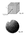
- Figs. 2A-2B illustrate a porous metal wire mesh 21 of a regenerative heat exchanger.
- the porous metal wire mesh 21 effectively acts like a thermal sponge.
- Figs. 3A-3B illustrate a porous matrix of metal or ceramic spheres 22 which forms a part of a regenerative heat exchanger.
- This porous matrix of metal or ceramic spheres 22 also acts like a thermal sponge.
- Fig. 4 illustrates an interconnected structure of two different materials such as solid copper 24, which has a high heat transfer coefficient, and solid lead 23, which has a high volumetric specific heat, of a regenerative heat exchanger.
- the heat is stored in a combination of solid materials and shapes optimized with respect to high volumetric specific heat and high heat transfer.
- the materials of the regenerative heat exchangers illustrated in Figs. 3-5 have in common that they are capable of storing heat coming from a cooling fluid and rejecting heat to a fluid.
- Cold storage device 11 reliably and passively enables the gas provided to thermal load 1 via feed line portion 20b to be kept from rising to an unacceptable temperature.
- cold storage device 11 reliably and passively prevents the temperature of the gas provided to thermal load 1 from rising to a unacceptably high temperature even during repair or replacement of cryogenic refrigerator 61 or 62 or its accompanying hardware.
- cryogenic refrigerators 61 and 62 When cryogenic refrigerators 61 and 62 are operating with a full refrigeration capacity, the gas flowing in the feed line of gas circuit 20 will be cooled to a cryogenic temperature. The gas cooled to this cryogenic temperature flowing through gas circuit 20 will cool cold storage device 11. Accordingly, cryogenic gas flowing through the feed line of gas circuit 20 will cool cold storage device 11 when cryogenic refrigerators 61 and 62 are properly operating at full refrigeration capacity.
- cold storage device 11 will cool the gas so that the gas provided to thermal load 1 does not rise to an unacceptable temperature (i.e., the thermal load is cooled so that it will remain in a superconductive state). Cold storage device 11 will cool the gas for a period while the full refrigeration capacity of cryogenic refrigerator 61 and/or 62 are being restored.
- the gas entering thermal load 1 maintains the thermal load (e.g., the superconducting coil of a generator rotor) at cryogenic temperatures by convection heat transfer and ensures that the thermal load may operate in superconducting conditions.
- the thermal load e.g., the superconducting coil of a generator rotor
- Return line 20c communicates the gas from thermal load 1 back to re-circulation device 2 via a coil in heat exchanger 3.
- the gas returned to re-circulation device 2 is at a warm temperature.
- Re-circulation device 2 may then re-circulate the gas by providing it to the cooling coil of heat exchanger 3.
- gas may instead be provided to the feed line portion 20a from cold gas circulator/fan 4 (shown in dashed line in order to represent it as an alternative).
- Cold gas provided from circulator/fan 4 will thus be provided to heat exchanger 8 via feed line portion 20a.
- circulator/fan 4 Since circulator/fan 4 is located within cold box 7, the cooling fluid remains rather cold as it circulates through circulator/fan 4.
- a heat exchanger thus does not need to be connected downstream from circulator/fan 4.
- a redundant circulator/fan (not shown in Fig. 1) can be connected to in parallel with circulator/fan 4 to increase the reliability of cooling.
- Gas from the cooling coil of heat exchanger 8 is passed through cold storage device 11 and then to thermal load 1 via fluid feed line portion 20b as discussed above. Warm gas flowing from thermal load 1 is returned to gas circulator/fan 4 via fluid return line portion 20c. Cold storage device 11 will be cooled by the gas flowing through it, whether originally from (i) cold gas circulator/fan 4 or (ii) re-circulation device 2 and heat exchanger 3, if the gas has been fully cooled in heat exchanger 8 via proper operation of cryogenic refrigerators 61-62 (e.g., operation of refrigerators 61-62 at full refrigeration capacity).
- cryogenic refrigerators 61-62 e.g., operation of refrigerators 61-62 at full refrigeration capacity
- cold storage device 11 will passively cool the gas passing therethrough as discussed above.
- the temperature of the gas provided to thermal load 1 is therefore reliably and passively kept at a acceptable cryogenic temperature even when cryogenic refrigerator 61 and/or 62 or its accompanying hardware 51 and/or 52 is being repaired or replaced.
- Cold box 7 encloses portions of the fluid feed line portions 20a, 20b, at least a portion of the fluid return line 20c, heat exchangers 3 and 8, at least part of cryogenic refrigerators 61 and 62 and gas circulator/fan 4.
- Cold box 7 is an insulated portion of the refrigeration system that is maintained at cryogenic temperatures. Cold box 7 may establish a vacuum around the components within the cold box.
- Fig. 5 is a schematic diagram of a cryogenic refrigeration system 70 in accordance with a second embodiment of the present invention.
- the components in cryogenic refrigeration system 70 that are common to the cryogenic refrigeration system 40 illustrated in Fig. 1 have been identified with common reference numbers. Only the differences between cryogenic refrigeration systems 70 and 40 will be discussed in detail.
- Cryogenic refrigeration system 70 includes a plurality of passive cold storage devices 101 and 102 connected in series as part of the fluid communication feed line of fluid circuit 20.
- Thermal connection devices 111 and 112 such as a heat pipes, solid conductive materials, or heat pipe type devices enclosing passive cold storage devices 101 and 102, thermally connect passive cold storage devices 101 and 102 to refrigerators 61 and 62, respectively.
- Refrigerators 61 and 62 thus cool passive cold storage devices 101 and 102, respectively, in normal operation.
- multiple refrigerators may cool each passive cold storage device 101 and 102.
- Each of the passive cold storage devices 101 and 102 may contain a porous matrix of materials as illustrated in Figs. 2-5. Also, while the exemplary embodiment illustrated in Fig.
- Cold box 6 encloses at least portions of refrigerators 61 and 62, thermal connection devices 111 and 112, and cold passive storage devices 101 and 102.
- cryogenic refrigeration system 70 provides several advantages, including higher efficiency and higher reliability.
- the higher efficiency results from operating individual refrigerators 61 and 62 at different cryogenic temperatures.
- Refrigerators 61 and 62 will thus cool cold storage devices 101 and 102 to different cryogenic temperatures.
- the most upsteam cold storage device 101 will have the warmest cryogen temperature and each subsequent cold storage device (e.g., device 102) will be cooled by a refrigerator to a progressively cooler temperature.
- the efficiency of refrigerators generally decreases with their cold temperature, making the refrigerator 61 for the most upstream cold storage device 101 more efficient than each subsequent stage.
- the time needed for system cool-down and warm-up is reduced.
- the higher reliability is facilitated in two ways.
- the first is having the ability to form one or more redundant module(s) form a cold storage device, thermal connection and corresponding refrigerator.
- the second is that only a fraction of the total refrigeration capacity is lost when an individual module is not working properly.
- refrigerator 61 cools cold storage device 101 via thermal connection device 111 to a first cryogenic temperature.
- Cold storage device 101 cools the fluid entering cold storage 101 through feed line portion 20a.
- the now cooled fluid exits cold storage device 101 and enters serially connected (downstream) cold storage device 102.
- Refrigerator 62 cools cold storage device 102 via thermal connection device 112 to a second cryogenic temperature which is lower than the first cryogenic temperature to which refrigerator 61 cools cold storage device 101.
- Cold storage device 102 cools the received fluid. If no further cold storage device(s) are serially connected downstream from the cold storage device 102, the cooling fluid exiting cold storage device 102 enters thermal load 1 via feed line portion 20b.
- the fluid then exits thermal load 1 and returns to heat exchanger 3 and re-circulation device 2 (or alternatively, circulator/fan 4) via fluid communication return line 20c.
- an additional passive cold storage device(s) e.g., passive cold storage device 103 cooled via thermal connection device 113 by cryogenic refrigerator 63 having re-circulating device 53-illustrated in dashed line in Fig. 4
- the cooling fluid exiting cold storage device 102 enters the additional passive cold storage device 103 prior to entering thermal load 1 via feed line portion 20b.
- Refrigerator 63 cools cold storage device 103 via thermal connection device 113 to a cryogenic temperature which is lower than the second cryogenic temperature to which refrigerator 62 cools cold storage device 102.
- Cold storage device 103 cools the received cooling fluid and passes the fluid to thermal load 1 via feed line portion 20b directly or through another (e.g., fourth, fifth, sixth, etc.) downstream passive cold storage device (not shown in Fig. 4).
- thermal connection device 111 and/or refrigerator 61 fails to operate properly so that cold storage device 101 operates only at a reduced or absent refrigeration capacity
- the fluid passing through the fluid feed line is still cooled by cold storage device 102 (presuming that device 102, thermal connection device 112 and refrigerator 62 are operating properly).
- cold storage device 102, thermal connection device 112 and/or refrigerator 62 fails to operate properly so that cold storage device 102 operates only at a reduced or absent refrigeration capacity
- the fluid passing through the fluid feed line is still cooled by cold storage device 101 (presuming that device 101, thermal connection device 111 and refrigerator 61 are operating properly).
- Thermal load 1 may thus be cooled in a reliable manner as only a portion of the refrigeration capacity will be lost when one particular cold storage device fails to properly cool the fluid being communicated to thermal load 1.
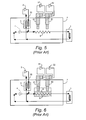
- FIGs. 6 and 7 illustrate known cryogenic refrigeration systems for cooling a thermal load. Components illustrated in Figs. 6 and 7 which are common to those earlier identified have been labeled with identical reference numbers.
Landscapes
- Engineering & Computer Science (AREA)
- Physics & Mathematics (AREA)
- Mechanical Engineering (AREA)
- Thermal Sciences (AREA)
- General Engineering & Computer Science (AREA)
- Chemical & Material Sciences (AREA)
- Dispersion Chemistry (AREA)
Abstract
Description
Claims (10)
- A cooling system (40) for providing cryogenic cooling fluid to an apparatus (1), the system (40) comprising:a re-circulation device (2);a passive cold storage device (11) having a porous matrix of material which directly contacts the cryogenic cooling fluid as the cryogenic cooling fluid passes through the passive cold storage device (11);a first portion of a fluid communication feed line (20a) fluidly connecting the re-circulation device (2) to the passive cold storage device (11);a second portion of the fluid communication feed line (20b) fluidly connecting the passive cold storage device (11) to the apparatus (1) for communicating cryogenic cooling fluid to the apparatus (1); anda fluid communication return line (20c) fluidly connecting the apparatus (1) to the re-circulation device (2).
- A cooling system (40) as in claim 1 wherein the passive cold storage device (11) comprises a regenerative heat exchanger.
- A cooling system (40) as in claim 1 wherein the porous matrix of material of the passive cold storage device (11) comprises a porous matrix of metal wire mesh (21).
- A cooling system (40) as in claim 1 wherein the porous matrix of material of the passive cold storage device (11) comprises a porous matrix of metal spheres (22).
- A cooling system (40) for providing a cooling fluid to an apparatus (1), the system (40) comprising:a cryogenic refrigerator (61 or 62) for cooling the fluid to a first temperature when operating at a first refrigeration capacity and cooling the fluid to a second temperature when operating at a second refrigeration capacity, the first temperature being lower than the second temperature and the first refrigeration capacity being higher than the second refrigeration capacity;a passive cold storage device (11) having a porous matrix of material which directly contacts the cryogenic cooling fluid as the cryogenic cooling fluid passes through the passive cold storage device (11);a first portion of a fluid communication feed line (20a) for communicating the fluid cooled by the cryogenic refrigerator (61 or 62) to the passive cold storage device (11), the fluid communicated to the passive cold storage device (11) cooling the passive cold storage device (11) when the fluid has been cooled to the first temperature by the cryogenic refrigerator (61 or 62) operating at the first refrigeration capacity, and the passive cold storage device (11) cooling the fluid when the fluid provided to the passive cold storage device (11) has been cooled to the second temperature by the cryogenic refrigerator (61 or 62) operating at the second refrigeration capacity; anda second portion of the fluid communication feed line (20b) fluidly connecting the passive cold storage device (11) to the apparatus (1) for communicating the fluid to the apparatus (1).
- A method of providing a cooling fluid to an apparatus (1), the method comprising:cooling the fluid utilizing a cryogenic refrigerator (61 or 62) to a first temperature when the cryogenic refrigerator (61 or 62) is operating at a first refrigeration capacity and to a second temperature when the cryogenic refrigerator (61 or 62) is operating at a second refrigeration capacity, the first temperature being lower than the second temperature and the first refrigeration capacity being higher than the second refrigeration capacity;communicating, as part of a fluid circuit (20), the fluid cooled by the cryogenic refrigerator (61 or 62) to a passive cold storage device (11) having a porous matrix of material directly contacting the fluid as the fluid passes through the passive cold storage device (11), the fluid cooling the passive cold storage device (11) when the fluid has been cooled to the first temperature by the cryogenic refrigerator (61 or 62) operating at the first refrigeration capacity and the passive cold storage device (11) cooling the fluid when the fluid has been cooled to the second temperature by the cryogenic refrigerator (61 or 62) operating at the second refrigeration capacity; andcommunicating, as part of the fluid circuit, the fluid from the passive cold storage device (11) to the apparatus (1).
- A method as in claim 6 wherein the passive cold storage device (11) comprises a regenerative heat exchanger.
- A cooling system (70) for providing cryogenic cooling fluid to an apparatus, the system (70) comprising:a re-circulation device (2);a fluid communication feed line (20a, 20b) connecting the re-circulation device (2) to the apparatus (1) for communicating the fluid to the apparatus, the fluid communication feed line (20a, 20b) including:a first passive cold storage device (101); anda second passive cold storage device (102) serially connected downstream from the first passive cold storage device (101); anda fluid communication return line (20c) connecting the apparatus (1) to the re-circulation device (2) for communicating the fluid from the apparatus (1) to the re-circulation device (2).
- A cooling system (70) as in claim 8 wherein at least one of the first and second passive cold storage devices (101, 102) comprises a porous matrix of material which directly contacts the cryogenic cooling fluid as the cryogenic cooling fluid passes therethrough.
- A method of providing a cooling fluid to an apparatus, the method comprising:communicating the fluid to the apparatus (1) through a fluid communication feed line (20a, 20b), the fluid communication feed line (20a, 20b) including a first passive cold storage device (101) and a second passive cold storage device (102) serially connected downstream from the first passive cold storage device (101); andcommunicating the fluid from the apparatus (1) to a re-circulating device through a fluid communication return line (20c).
Applications Claiming Priority (2)
| Application Number | Priority Date | Filing Date | Title |
|---|---|---|---|
| US10/604,415 US7003977B2 (en) | 2003-07-18 | 2003-07-18 | Cryogenic cooling system and method with cold storage device |
| US604415 | 2003-07-18 |
Publications (3)
| Publication Number | Publication Date |
|---|---|
| EP1498670A2 true EP1498670A2 (en) | 2005-01-19 |
| EP1498670A3 EP1498670A3 (en) | 2005-06-29 |
| EP1498670B1 EP1498670B1 (en) | 2007-05-30 |
Family
ID=33477043
Family Applications (1)
| Application Number | Title | Priority Date | Filing Date |
|---|---|---|---|
| EP04254294A Expired - Lifetime EP1498670B1 (en) | 2003-07-18 | 2004-07-16 | Cryogenic cooling system and method with cold storage device |
Country Status (4)
| Country | Link |
|---|---|
| US (1) | US7003977B2 (en) |
| EP (1) | EP1498670B1 (en) |
| JP (1) | JP4667778B2 (en) |
| DE (1) | DE602004006674T2 (en) |
Cited By (4)
| Publication number | Priority date | Publication date | Assignee | Title |
|---|---|---|---|---|
| WO2007009611A1 (en) * | 2005-07-19 | 2007-01-25 | Linde Aktiengesellschaft | Method and device for cooling and/or liquefying a fluid |
| ITFI20090212A1 (en) * | 2009-10-05 | 2011-04-06 | Univ Firenze | CRYOGENIC SYSTEM WITH CHANGE OF SOLID-LIQUID PHASE FOR LOW TEMPERATURE INDUSTRIAL PROCESSES. |
| WO2011143398A1 (en) * | 2010-05-12 | 2011-11-17 | Brooks Automation, Inc. | System and method for cryogenic cooling |
| EP4350250A1 (en) * | 2022-10-07 | 2024-04-10 | Hamilton Sundstrand Corporation | Cryocooler with transient thermal storage |
Families Citing this family (29)
| Publication number | Priority date | Publication date | Assignee | Title |
|---|---|---|---|---|
| US7185501B2 (en) * | 2004-12-16 | 2007-03-06 | General Electric Company | Cryogenic cooling system and method with backup cold storage device |
| CA2551062C (en) * | 2006-06-08 | 2012-02-14 | Jose Lourenco | Method for re-gasification of liquid natural gas |
| US7466046B2 (en) * | 2006-07-05 | 2008-12-16 | General Electric Company | Methods and apparatus for operating an electric machine |
| US7821164B2 (en) * | 2007-02-15 | 2010-10-26 | General Electric Company | Method and apparatus for a superconducting generator driven by wind turbine |
| US8534079B2 (en) * | 2010-03-18 | 2013-09-17 | Chart Inc. | Freezer with liquid cryogen refrigerant and method |
| WO2011132231A1 (en) * | 2010-04-23 | 2011-10-27 | 住友重機械工業株式会社 | Cooling system and cooling method |
| CN102055283A (en) * | 2011-01-18 | 2011-05-11 | 北京鹏发欣光电力电子科技有限公司 | Evaporation cooling permanent magnet motor |
| FR2975176B1 (en) * | 2011-05-09 | 2016-03-18 | Air Liquide | DEVICE AND METHOD FOR CRYOGENIC COOLING |
| CA2763081C (en) | 2011-12-20 | 2019-08-13 | Jose Lourenco | Method to produce liquefied natural gas (lng) at midstream natural gas liquids (ngls) recovery plants. |
| CA2772479C (en) | 2012-03-21 | 2020-01-07 | 1304342 Alberta Ltd. | Temperature controlled method to liquefy gas and a production plant using the method. |
| CA2790961C (en) | 2012-05-11 | 2019-09-03 | Jose Lourenco | A method to recover lpg and condensates from refineries fuel gas streams. |
| CA2787746C (en) | 2012-08-27 | 2019-08-13 | Mackenzie Millar | Method of producing and distributing liquid natural gas |
| EP2923160B1 (en) * | 2012-11-21 | 2021-01-13 | D-Wave Systems Inc. | System for cryogenic refrigeration |
| CA2798057C (en) | 2012-12-04 | 2019-11-26 | 1304342 Alberta Ltd. | A method to produce lng at gas pressure letdown stations in natural gas transmission pipeline systems |
| CA2813260C (en) | 2013-04-15 | 2021-07-06 | Mackenzie Millar | A method to produce lng |
| CN103307798B (en) * | 2013-06-21 | 2015-02-18 | 中国科学院上海技术物理研究所 | Coaxial pulse tube refrigerator and infrared device compact coupled structure and manufacturing method |
| US10107543B2 (en) * | 2013-11-21 | 2018-10-23 | Shahin Pourrahimi | Cryogenic thermal storage |
| KR101562887B1 (en) | 2014-03-11 | 2015-10-26 | 한국과학기술원 | Oscillating flow apparatus, active magnetic regenerative refrigerator system the oscillating flow apparatus and oscillating flow method |
| DE102014208437A1 (en) * | 2014-05-06 | 2015-11-12 | Siemens Aktiengesellschaft | Cooling device for at least two components to be cooled, rail vehicle and method of cooling |
| US10378803B2 (en) | 2014-08-08 | 2019-08-13 | D-Wave Systems Inc. | Systems and methods for electrostatic trapping of contaminants in cryogenic refrigeration systems |
| CA2958091C (en) | 2014-08-15 | 2021-05-18 | 1304338 Alberta Ltd. | A method of removing carbon dioxide during liquid natural gas production from natural gas at gas pressure letdown stations |
| CA2997628C (en) | 2015-09-16 | 2022-10-25 | 1304342 Alberta Ltd. | A method of preparing natural gas at a gas pressure reduction stations to produce liquid natural gas (lng) |
| JP6703195B2 (en) * | 2016-12-20 | 2020-06-03 | スミトモ (エスエイチアイ) クライオジェニックス オブ アメリカ インコーポレイテッドSumitomo(SHI)Cryogenics of America,Inc. | System for heating and cooling superconducting magnets |
| JP6975019B2 (en) * | 2017-10-27 | 2021-12-01 | 住友重機械工業株式会社 | Cryogenic system |
| FR3090840B1 (en) * | 2018-12-20 | 2021-01-08 | Univ Franche Comte | Regenerator and method of manufacturing such a regenerator |
| KR20240026226A (en) | 2021-07-29 | 2024-02-27 | 스미토모 크라이어제닉스 오브 아메리카 인코포레이티드 | Circulating cryogenic chiller system placed in series |
| JP2023156879A (en) * | 2022-04-13 | 2023-10-25 | 株式会社東芝 | Cryogenic cooling system, superconducting device, and operating method of cryogenic cooling system |
| KR102842702B1 (en) * | 2022-08-25 | 2025-08-06 | 주식회사 패리티 | Cryogenic Refrigeration Assembly and Distillation Column Comprising Same |
| JP2024055004A (en) * | 2022-10-06 | 2024-04-18 | 株式会社東芝 | Cryogenic cooling devices and superconducting devices |
Family Cites Families (21)
| Publication number | Priority date | Publication date | Assignee | Title |
|---|---|---|---|---|
| NL6806544A (en) * | 1968-05-09 | 1969-11-11 | ||
| US4404808A (en) * | 1981-08-10 | 1983-09-20 | Helix Technology Corporation | Cryogenic refrigerator with non-metallic regenerative heat exchanger |
| DD265570A1 (en) * | 1987-11-02 | 1989-03-08 | Hochvakuum Dresden Veb | MATRIX MATERIAL FOR REGENERATORS AND METHOD FOR PRODUCING A FINE-BRAZED BLEACHING TAPE |
| JPH0569563U (en) * | 1992-02-28 | 1993-09-21 | 住友重機械工業株式会社 | Cryogenic cooling device |
| JP3104387B2 (en) * | 1992-04-08 | 2000-10-30 | ダイキン工業株式会社 | Stirling refrigerator |
| US5429177A (en) | 1993-07-09 | 1995-07-04 | Sierra Regenators, Inc. | Foil regenerator |
| US5548168A (en) | 1994-06-29 | 1996-08-20 | General Electric Company | Superconducting rotor for an electrical machine |
| US5606870A (en) * | 1995-02-10 | 1997-03-04 | Redstone Engineering | Low-temperature refrigeration system with precise temperature control |
| US5513498A (en) | 1995-04-06 | 1996-05-07 | General Electric Company | Cryogenic cooling system |
| US5647218A (en) | 1995-05-16 | 1997-07-15 | Kabushiki Kaisha Toshiba | Cooling system having plural cooling stages in which refrigerate-filled chamber type refrigerators are used |
| JP3691904B2 (en) * | 1995-05-16 | 2005-09-07 | 株式会社東芝 | Cooling system and superconducting magnet device |
| JPH1151583A (en) * | 1997-08-05 | 1999-02-26 | Tokyo Gas Co Ltd | Regenerator, regenerative heat exchanger and regenerative combustion device |
| JP3251911B2 (en) | 1998-12-21 | 2002-01-28 | 東京瓦斯株式会社 | Heat storage (cool storage) panel, heat storage (cool storage) system, and heat storage (cool storage) method of the system |
| US6318090B1 (en) * | 1999-09-14 | 2001-11-20 | Iowa State University Research Foundation, Inc. | Ductile magnetic regenerator alloys for closed cycle cryocoolers |
| US6347522B1 (en) * | 2000-01-11 | 2002-02-19 | American Superconductor Corporation | Cooling system for HTS machines |
| JP2002125555A (en) * | 2000-10-26 | 2002-05-08 | Nakajima:Kk | Ground bait scoop with fishhook releaser |
| US6415613B1 (en) | 2001-03-16 | 2002-07-09 | General Electric Company | Cryogenic cooling system with cooldown and normal modes of operation |
| US6438969B1 (en) | 2001-07-12 | 2002-08-27 | General Electric Company | Cryogenic cooling refrigeration system for rotor having a high temperature super-conducting field winding and method |
| US6442949B1 (en) | 2001-07-12 | 2002-09-03 | General Electric Company | Cryongenic cooling refrigeration system and method having open-loop short term cooling for a superconducting machine |
| JP2003336923A (en) | 2002-05-20 | 2003-11-28 | Central Japan Railway Co | Cryogenic refrigeration equipment |
| US6640552B1 (en) * | 2002-09-26 | 2003-11-04 | Praxair Technology, Inc. | Cryogenic superconductor cooling system |
-
2003
- 2003-07-18 US US10/604,415 patent/US7003977B2/en not_active Expired - Lifetime
-
2004
- 2004-07-16 JP JP2004209302A patent/JP4667778B2/en not_active Expired - Fee Related
- 2004-07-16 EP EP04254294A patent/EP1498670B1/en not_active Expired - Lifetime
- 2004-07-16 DE DE602004006674T patent/DE602004006674T2/en not_active Expired - Lifetime
Cited By (8)
| Publication number | Priority date | Publication date | Assignee | Title |
|---|---|---|---|---|
| WO2007009611A1 (en) * | 2005-07-19 | 2007-01-25 | Linde Aktiengesellschaft | Method and device for cooling and/or liquefying a fluid |
| ITFI20090212A1 (en) * | 2009-10-05 | 2011-04-06 | Univ Firenze | CRYOGENIC SYSTEM WITH CHANGE OF SOLID-LIQUID PHASE FOR LOW TEMPERATURE INDUSTRIAL PROCESSES. |
| WO2011143398A1 (en) * | 2010-05-12 | 2011-11-17 | Brooks Automation, Inc. | System and method for cryogenic cooling |
| EP3040646A1 (en) * | 2010-05-12 | 2016-07-06 | Brooks Automation, Inc. | Method for cryogenic cooling |
| US10156386B2 (en) | 2010-05-12 | 2018-12-18 | Brooks Automation, Inc. | System and method for cryogenic cooling |
| US11215384B2 (en) | 2010-05-12 | 2022-01-04 | Edwards Vacuum Llc | System and method for cryogenic cooling |
| EP4350250A1 (en) * | 2022-10-07 | 2024-04-10 | Hamilton Sundstrand Corporation | Cryocooler with transient thermal storage |
| US12455100B2 (en) | 2022-10-07 | 2025-10-28 | Hamilton Sundstrand Corporation | Cryocooler with transient thermal storage |
Also Published As
| Publication number | Publication date |
|---|---|
| DE602004006674T2 (en) | 2008-01-24 |
| DE602004006674D1 (en) | 2007-07-12 |
| EP1498670B1 (en) | 2007-05-30 |
| US7003977B2 (en) | 2006-02-28 |
| JP4667778B2 (en) | 2011-04-13 |
| US20050086974A1 (en) | 2005-04-28 |
| EP1498670A3 (en) | 2005-06-29 |
| JP2005043044A (en) | 2005-02-17 |
Similar Documents
| Publication | Publication Date | Title |
|---|---|---|
| EP1498670B1 (en) | Cryogenic cooling system and method with cold storage device | |
| US7185501B2 (en) | Cryogenic cooling system and method with backup cold storage device | |
| CN103002711B (en) | Sub-cooling unit for cooling system and method | |
| US6347522B1 (en) | Cooling system for HTS machines | |
| US7263845B2 (en) | Backup cryogenic refrigeration system | |
| KR102506491B1 (en) | Fault-tolerant cryogenic cooling system | |
| EP3069159B1 (en) | Superconducting magnet system including thermally efficient ride-through system and method of cooling superconducting magnet system | |
| US10030919B2 (en) | Cooling apparatus for superconductor | |
| GB2361523A (en) | Superconducting magnet apparatus | |
| US20020134533A1 (en) | System for transmitting electric energy in superconductivity conditions and method for refrigerating in continuous a superconducting cable | |
| US6679066B1 (en) | Cryogenic cooling system for superconductive electric machines | |
| JP5380310B2 (en) | Cryogenic refrigerator | |
| JP3955022B2 (en) | Refrigeration equipment | |
| EP1931926B1 (en) | Refrigeration system for superconducting devices | |
| EP1198802B1 (en) | System for transmitting electric energy in superconductivity conditions and method for refrigerating in continuous a superconducting cable | |
| US11153991B2 (en) | Method and apparatus for cooling a load and system comprising corresponding apparatus and load | |
| Longsworth | Serviceable refrigerator system for small superconducting devices | |
| EP3865789A1 (en) | Cryogenic system | |
| Longsworth et al. | described. The refrigeration system incorporates new (passive) thermal |
Legal Events
| Date | Code | Title | Description |
|---|---|---|---|
| PUAI | Public reference made under article 153(3) epc to a published international application that has entered the european phase |
Free format text: ORIGINAL CODE: 0009012 |
|
| AK | Designated contracting states |
Kind code of ref document: A2 Designated state(s): AT BE BG CH CY CZ DE DK EE ES FI FR GB GR HU IE IT LI LU MC NL PL PT RO SE SI SK TR |
|
| AX | Request for extension of the european patent |
Extension state: AL HR LT LV MK |
|
| PUAL | Search report despatched |
Free format text: ORIGINAL CODE: 0009013 |
|
| AK | Designated contracting states |
Kind code of ref document: A3 Designated state(s): AT BE BG CH CY CZ DE DK EE ES FI FR GB GR HU IE IT LI LU MC NL PL PT RO SE SI SK TR |
|
| AX | Request for extension of the european patent |
Extension state: AL HR LT LV MK |
|
| 17P | Request for examination filed |
Effective date: 20051229 |
|
| AKX | Designation fees paid |
Designated state(s): CH DE GB LI |
|
| GRAP | Despatch of communication of intention to grant a patent |
Free format text: ORIGINAL CODE: EPIDOSNIGR1 |
|
| GRAS | Grant fee paid |
Free format text: ORIGINAL CODE: EPIDOSNIGR3 |
|
| GRAA | (expected) grant |
Free format text: ORIGINAL CODE: 0009210 |
|
| AK | Designated contracting states |
Kind code of ref document: B1 Designated state(s): CH DE GB LI |
|
| REG | Reference to a national code |
Ref country code: GB Ref legal event code: FG4D |
|
| REG | Reference to a national code |
Ref country code: CH Ref legal event code: EP |
|
| REF | Corresponds to: |
Ref document number: 602004006674 Country of ref document: DE Date of ref document: 20070712 Kind code of ref document: P |
|
| REG | Reference to a national code |
Ref country code: CH Ref legal event code: NV Representative=s name: SERVOPATENT GMBH |
|
| REG | Reference to a national code |
Ref country code: CH Ref legal event code: PFA Owner name: GENERAL ELECTRIC COMPANY Free format text: GENERAL ELECTRIC COMPANY#1 RIVER ROAD#SCHENECTADY, NY 12345 (US) -TRANSFER TO- GENERAL ELECTRIC COMPANY#1 RIVER ROAD#SCHENECTADY, NY 12345 (US) |
|
| PLBE | No opposition filed within time limit |
Free format text: ORIGINAL CODE: 0009261 |
|
| STAA | Information on the status of an ep patent application or granted ep patent |
Free format text: STATUS: NO OPPOSITION FILED WITHIN TIME LIMIT |
|
| 26N | No opposition filed |
Effective date: 20080303 |
|
| PGFP | Annual fee paid to national office [announced via postgrant information from national office to epo] |
Ref country code: CH Payment date: 20190624 Year of fee payment: 16 |
|
| PGFP | Annual fee paid to national office [announced via postgrant information from national office to epo] |
Ref country code: GB Payment date: 20190624 Year of fee payment: 16 Ref country code: DE Payment date: 20190620 Year of fee payment: 16 |
|
| REG | Reference to a national code |
Ref country code: CH Ref legal event code: PCAR Free format text: NEW ADDRESS: WANNERSTRASSE 9/1, 8045 ZUERICH (CH) |
|
| REG | Reference to a national code |
Ref country code: DE Ref legal event code: R119 Ref document number: 602004006674 Country of ref document: DE |
|
| REG | Reference to a national code |
Ref country code: CH Ref legal event code: PL |
|
| GBPC | Gb: european patent ceased through non-payment of renewal fee |
Effective date: 20200716 |
|
| PG25 | Lapsed in a contracting state [announced via postgrant information from national office to epo] |
Ref country code: GB Free format text: LAPSE BECAUSE OF NON-PAYMENT OF DUE FEES Effective date: 20200716 Ref country code: CH Free format text: LAPSE BECAUSE OF NON-PAYMENT OF DUE FEES Effective date: 20200731 Ref country code: LI Free format text: LAPSE BECAUSE OF NON-PAYMENT OF DUE FEES Effective date: 20200731 |
|
| PG25 | Lapsed in a contracting state [announced via postgrant information from national office to epo] |
Ref country code: DE Free format text: LAPSE BECAUSE OF NON-PAYMENT OF DUE FEES Effective date: 20210202 |