EP1498527A1 - Magnetic needle selecting device of weft knitting machine - Google Patents
Magnetic needle selecting device of weft knitting machine Download PDFInfo
- Publication number
- EP1498527A1 EP1498527A1 EP03747212A EP03747212A EP1498527A1 EP 1498527 A1 EP1498527 A1 EP 1498527A1 EP 03747212 A EP03747212 A EP 03747212A EP 03747212 A EP03747212 A EP 03747212A EP 1498527 A1 EP1498527 A1 EP 1498527A1
- Authority
- EP
- European Patent Office
- Prior art keywords
- carriage
- needle
- power
- magnetic
- moving speed
- Prior art date
- Legal status (The legal status is an assumption and is not a legal conclusion. Google has not performed a legal analysis and makes no representation as to the accuracy of the status listed.)
- Granted
Links
Images




Classifications
-
- D—TEXTILES; PAPER
- D04—BRAIDING; LACE-MAKING; KNITTING; TRIMMINGS; NON-WOVEN FABRICS
- D04B—KNITTING
- D04B15/00—Details of, or auxiliary devices incorporated in, weft knitting machines, restricted to machines of this kind
- D04B15/66—Devices for determining or controlling patterns ; Program-control arrangements
-
- D—TEXTILES; PAPER
- D04—BRAIDING; LACE-MAKING; KNITTING; TRIMMINGS; NON-WOVEN FABRICS
- D04B—KNITTING
- D04B15/00—Details of, or auxiliary devices incorporated in, weft knitting machines, restricted to machines of this kind
- D04B15/66—Devices for determining or controlling patterns ; Program-control arrangements
- D04B15/82—Devices for determining or controlling patterns ; Program-control arrangements characterised by the needle cams used
-
- D—TEXTILES; PAPER
- D04—BRAIDING; LACE-MAKING; KNITTING; TRIMMINGS; NON-WOVEN FABRICS
- D04B—KNITTING
- D04B15/00—Details of, or auxiliary devices incorporated in, weft knitting machines, restricted to machines of this kind
- D04B15/66—Devices for determining or controlling patterns ; Program-control arrangements
- D04B15/68—Devices for determining or controlling patterns ; Program-control arrangements characterised by the knitting instruments used
- D04B15/78—Electrical devices
Definitions
- This invention relates to a magnetic-type needle selection device of a flat knitting machine.
- Knitting needles selected by a selector actuator according to knitting data are forward and backward operated by a group of cams mounted on a carriage that reciprocates over the needle beds, so that the flat knitting machine can knit fabrics having a jacquard pattern, a design pattern, etc.
- a device using a fixed electromagnet is known as a needle-selecting means for selecting knitting needles that are forward and backward operated.
- a device using a fixed electromagnet can select needles at a high speed and has fewer troubles during knitting because a selector actuator is fixed.
- the fixed electromagnet of the selector actuator can be classified into two types one of which is a current-application hold type that is adsorbed to an end of a desired selector by applying an electric current to the coil of a pole from a power supply control unit and the other of which is a current-application release type that releases the adsorption of an end of a desired selector by applying an electric current to the coil of the pole from the power supply control unit.
- the needle selection device of the current-application release type has an advantage, for example, in enabling easy handling at the time of a power failure or at the time of power recovery after a power failure.
- a carriage is provided with a selector actuator made up of a permanent magnet and an electromagnet excited by being supplied with electric power from the power supply control unit.
- This selector actuator selects desired needles by adsorbing the selector by means of the permanent magnet, by canceling the magnetic flux of the permanent magnet by use of the magnetic flux of the electromagnet excited by the current supplied from the power supply control unit, and by undoing the adsorption of the selector.
- a current-application interval from the start of current application by which the electromagnet is actuated to the end thereof is set at a predetermined interval, for example, at 1/2 of a gauge pitch.
- detecting elements "A" and “B” that detect the selector have been conventionally provided in order to detect a power-supply starting position and a power-supply stopping position, for example, as shown in Fig. 6.
- the distance between knitting needles is detected as four positions “a” to “d” as shown in Fig. 7A and Fig. 7B by turning the detecting elements "A” and "B” on and off.
- the power-supply starting position E1 and the power-supply stopping position E2 are controlled so that the power supply (i.e., current application) is started at, for example, position "b" is stopped at position "d.”
- a desired magnetic flux G is generated in the electromagnet as shown in Fig. 7 by being supplied with an electric current from the power supply means as mentioned above.
- a positional coincidence is established between the center PC of a current-application interval P determined by the power-supply starting point "b" and the power-supply stopping point “d” and the center WC in the width direction W of a selector to be selected when the carriage moves at a general moving speed (see Fig. 6).
- the flat knitting machine knits fabrics while reciprocating the carriage over needle beds.
- the carriage is repeatedly accelerated and decelerated by its reversals, so that the moving speed of the carriage in one course is not always constant. Not only when the carriage is reversed but also when the carriage is midway in the course, cases occur in which the moving speed of the carriage is changed.
- a current-application interval from the start of a power supply operation by which the electromagnet is actuated to the end thereof is set at, for example, 1/2 of the gauge pitch of the flat knitting machine. Therefore, a knitting machine having a coarse gauge can cope with a change in moving speed of the carriage with a relatively large margin.
- a knitting machine having a fine gauge has a current-application interval P1 shortened as shown in Fig. 5A and Fig. 5B.
- the period of time of an F portion that effectively acts on a selector selected by the electromagnet i.e., the period of time of a flat portion obtained by subtracting a rise time S from a current-application interval P in the figures
- the rise time S of a magnetic flux generated in the electromagnet by the power supply means is substantially constant regardless of the moving speed of the carriage.
- the F portion is dislocated toward the upper side in the moving direction of the carriage from the center of a selector to be selected.
- the magnetic flux of the electromagnet rises late when the carriage moves at a high speed.
- the carriage moves at a low speed if the power-supply starting point of time is early, magnetism affects a next selector on the forward side, and, if the power-supply stopping point of time is late, residual magnetism affects the following selector. Therefore, disadvantageously, an error in selecting needles is liable to occur.
- a magnetic-type needle selection device of a flat knitting machine of the present invention comprises at least one pair of needle beds; a carriage that moves over the needle beds; a plurality of needle grooves formed in each needle bed, the needle grooves slidably containing needles; a magnetic needle-selection mechanism provided on the carriage, the magnetic needle-selection mechanism capable of selecting needles by supplying an electric current to an electromagnetic coil, by canceling a magnetic flux of an adsorption surface of a selector actuator, and by releasing a knitting member, such as a selector, that has been adsorbed to the adsorption surface from the adsorption surface; the magnetic-type needle selection device of the flat knitting machine characterized by further comprising a carriage speed detecting means for detecting the moving speed of the carriage; and a power supply control means for controlling a current-application interval of an electric current supplied to the selector actuator in accordance with a carriage speed detected by the carriage speed detecting means.
- the power supply control means is structured so that, when the moving speed of the carriage is high, the current-application interval becomes longer by moving further forward a power-supply starting position than when the moving speed of the carriage is medium.
- the power supply control means is structured so that the power-supply stopping position is moved further backward when the moving speed of the carriage is high than when the moving speed of the carriage is medium.
- the power supply control means is structured so that the power-supply starting position is moved further backward when the moving speed of the carriage is low than when the moving speed of the carriage is medium, and the current-application interval is shortened by moving further forward the power-supply stopping position.
- the needles are selectively guided to three positions, i.e., an advanced position (knit), an intermediate position (tuck), and a stationary position (welt), which are called "A position,” “H position,” and "B position,” respectively.
- the needle selection device of the present embodiment can be utilized for stitch transfer, etc., and the stationary position serves also as the initial position of the needle.
- a movement toward a trick gap between a pair of needle beds is defined as an advancement, and a movement in the opposite direction is defined as a withdrawal.
- cams of the carriage one that is closer to the needle beds is defined as a higher cam, and one that is more distant from the needle beds is defined as a lower cam.
- Fig. 1 is a longitudinal sectional side view of a knitting needle part contained in a needle groove of a needle plate.
- the needle bed 1 is provided with a plurality of grooves 2 parallel to each other.
- a needle plate 3 is fitted into the groove 2, and a needle groove 4 is formed between two adjoining needle plates 3 and 3.
- a metal strip 5 is passed through a large number of needle plates 3 arranged in a row so as to prevent the needles 6 and the like from coming off.
- a needle 6, a needle jack 7, a select jack 8, and a selector 9 are slidably inserted in each needle groove 4.
- the needle jack 7 has its tip fitted in the tail of the needle 6.
- a needle jack butt 10 is formed at the center of the needle jack 7.
- An elastic leg portion 7a provided in the tail of the needle jack 7 presses the needle jack butt 10 so that the needle jack butt 10 will protrude out of the needle groove 4.
- the tip of the select jack 8 is located above the needle jack 7, and the upper surface of the center of the select jack 8 is in contact with a wire 11.
- the tail of the select jack 8 has fork ends 12 and 13, which are in contact with a wire 14.
- the wires 11 and 14 pierce the needle plates 3 and hold the select jack 8 in each needle groove 4 while being in contact with the upper surface of the select jack 8.
- the select jack 8 reciprocates in the needle groove 4, and its most advanced position coincides with "A position" of the select jack butt 15 where its tip is brought into contact with the wire 16.
- "A position,” “H position, “ and “B position” are determined by three dents, respectively, that are formed in the upper surface of the lower leg 17 of the fork ends 12, 13.
- the top end of the selector 9 has a tip that is engaged with the butt 18 to advance the select jack 8 toward the "H position" or "A position.”
- the tail end of the selector 9 has an armature 21 that is adsorbed by a magnetic needle-selection mechanism 20 described later.
- the armature 21 is in a state of protruding from the tail end of the needle groove 4.
- the upper surface of the selector 9 is provided with three butts 22, 23, and 24 that are operated by a group of cams (not shown) of the carriage 28.
- a bracket 26 having an L-shaped section is provided on a portion that protrudes backward beyond the tail end of the selector 9, and the needle selection mechanism 20 is comprised of a selector actuator 27 mounted to face the undersurface of the armature 21 and a power supply control device 40 described later.
- the actuator 27 is provided with two upper and lower rows of adsorption surfaces 30 magnetized by permanent magnets (not shown) and at first and second needle selection sites 31 and 32 arranged at an appropriate interval.
- the selection sites 31 and 32 have pole pieces 31a, 31b, 32a, and 32b of the electromagnetic coils (not shown) of current-application release type electromagnets.
- Each of the pole pieces 31a, 31b, 32a, and 32b is flush with the adsorption surface 30.
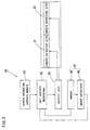
- the power supply control device 40 that is a constituent element of the needle selection mechanism 20 is made up of a position detector 41 that detects the position of the carriage, a carriage speed detector 47 that detects the moving speed of the carriage 28 in real time, and a coil current determiner 52 that determines power-supply starting and stopping positions in accordance with a carriage speed detected by the carriage speed detector 47.
- a current-application interval during which an electric current is applied is controlled by determining the power-supply starting and stopping positions.
- the position detector 41 includes a sensor 44 that reads information of a linear scale 43
- the carriage speed detector 47 includes a speed calculator 48 that receives a pulse signal from the sensor 44 and then calculates the speed of the carriage 28 in real time based on the quantity or period of the pulse signal.
- the linear scale 43 is attached to a supporting arm 46 along the longitudinal direction of the needle bed 1, i.e., along the moving direction of the carriage 28.
- the supporting arm 46 is mounted on a frame 45 that supports the needle bed 1.
- a magnetic substance is embedded in a part of the upper surface of the linear scale 43 on the side of the carriage 28 in the form of a so-called magnet scale like a bar code.
- the sensor 44 that reads the magnetic substance embedded in the surface of the linear scale 43 is a magnetic sensor attached to the lower end of the carriage 28 with the bracket 26 therebetween in a state in which its reading surface faces the upper surface of the linear scale 43.
- the sensor 44 of the position detector 41 is high in resolution, and therefore can detect the position of the carriage 28 with high resolution to accurately ascertain power-supply starting and stopping positions.
- the power-supply starting position E1 and the power-supply stopping position E2 of the pole pieces 31a, 31b, 32a, and 32b to the coils are determined by a needle selection pattern memory 51 in the needle selection data that is part of knitting data and by a coil current determiner 52 that determines a power supply position, where an electric current is supplied to the coils, in accordance with a detection signal regarding the position of the carriage that is emitted from the sensor 44 and in accordance with the speed of the carriage 28 detected by the carriage speed detector 47.
- the space between the power-supply starting position E1 and the power-supply stopping position E2 shown in Fig. 7 is a current-application interval P.
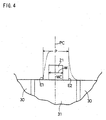
- the power-supply starting position E1 and the power-supply stopping position E2, at which electric power supply to the electromagnetic coils by which the pole pieces 31a, 31b, 32a, and 32b are excited is started and stopped, are basically set as positions for a medium speed within the range of the moving speed of the carriage 28, and, as shown in Fig. 4, a positional coincidence is established between the center PC of the current-application interval P and the center WC in the width direction W of the selector 9.
- the moving speed of the carriage 28 ranges from 0.0 to 1.5m/s.
- the speed closer to the maximum speed is defined as high, the intermediate speed is defined as medium, and the speed closer to the stop is defined as low.
- a delay in the rise of a magnetic flux is compensated by advancing the power-supply starting position E1 in this way, and the selector 9 can be reliably released by delaying the power-supply stopping position E2. Therefore, the knitting machine can cope with a case in which, for example, the knitting machine is cooled so that the viscosity of a lubricant becomes high or a case in which the adhesion of dust or the like makes the movement of the selector slow.
- Knitting needles 6 selected by the power supply control device 40 are operated as described in, for example Japanese Published Unexamined Patent Application No. H9-241952 so as to knit fabrics in response to the reciprocation of the carriage 28 of the knitting machine having the magnetic-type needle selection device structured as mentioned above.
- the position where electric power is supplied to the coils of the pole pieces 31a, 31b, 32a, and 32b is determined by the coil current determiner 52 of the power supply control device 40. That is, a power-supply starting position E3 and a power-supply stopping position E4 are determined as shown in Fig. 5A.
- the current-application interval is P1. This is transmitted to the control unit 53, and, when a position detected by the position detector 41 coincides with the power-supply starting position E3 where electric power is supplied to the coils, a power supply operation is started, and, when that position coincides with the power-supply stopping position E4, a power supply operation is stopped.
- the current-application interval P1 is lengthened because the power-supply starting position E3 is moved further forward than the power-supply starting position E1 where the moving speed of the carriage 28 is medium and because the power-supply stopping position E4 is moved further backward than the power-supply stopping position E2 as shown in Fig. 5B when electric power is supplied to the needle selection sites 31 and 32.
- a power-supply starting position and a power-supply stopping position where the supply of electric power to the coils is started and stopped are determined by the needle selection pattern memory 51 in the needle selection data and by the coil current determiner 52 that determines a power supply position, where an electric current is supplied to the coils, in accordance with a detection signal regarding the position of the carriage that is emitted from the sensor 44 and in accordance with the speed of the carriage 28 detected by the carriage speed detector 47, which are not shown in the attached drawings.
- the armature 21 adsorbed to the two upper and lower rows of flat adsorption surfaces 30 magnetized by the permanent magnets is released from its adsorption.
- the present invention can be, of course, embodied in a case in which needles are selected by allowing the armature to be adsorbed to the pole pieces excited by being supplied with electric power.
- the current-application interval may be controlled in accordance with the speed of the carriage in order to select needles with higher accuracy, and the value of an electric current to be applied may be controlled in accordance with the number of selectors adsorbed thereto.
- the quantity of magnetic flux of the needle selection sites may be measured by a sensor, such as a hall element, so as to generate magnetic flux needed to cancel the quantity of magnetic flux corresponding to an obtained value.
- the power-supply starting and stopping positions are finely adjusted and controlled in real time in accordance with the speed of the carriage detected by the carriage speed detecting means.
- a table may be provided which has data in which the power-supply starting and stopping positions are set, for example, for high speed, medium speed, and low speed, and the power-supply starting and stopping positions may be controlled according to the table for each speed.
- a magnetic substance is embedded in a part of the upper surface of the linear scale on the side of the carriage so as to form a magnet scale.
- any linear scale capable of coping with high resolution may be employed in the present invention.
- the speed of the carriage is described as high, medium, and low.
- the power-supply starting and stopping positions corresponding to each carriage speed can be, of course, controlled without levels because the high speed, medium speed, and low speed described in the present invention are relative.
Landscapes
- Engineering & Computer Science (AREA)
- Textile Engineering (AREA)
- Knitting Machines (AREA)
Abstract
Description
Claims (4)
- A magnetic-type needle selection device of a flat knitting machine comprising: at least one pair of needle beds; a carriage that moves over the needle beds; a plurality of needle grooves formed in each needle bed, the needle grooves slidably containing needles; a magnetic needle-selection mechanism provided on the carriage, the magnetic needle-selection mechanism capable of selecting needles by supplying an electric current to an electromagnetic coil, by canceling a magnetic flux of an adsorption surface of a selector actuator, and by releasing a knitting member that has been adsorbed to the adsorption surface from the adsorption surface; the magnetic-type needle selection device of the flat knitting machine further comprising:a carriage speed detecting means for detecting the moving speed of the carriage; anda power supply control means for controlling a current-application interval of an electric current supplied to the selector actuator in accordance with a carriage speed detected by the carriage speed detecting means.
- The magnetic-type needle selection device of the flat knitting machine as set forth in Claim 1, characterized in that the power supply control means is structured so that, when the moving speed of the carriage is high, the current-application interval becomes longer by moving further forward a power-supply starting position than when the moving speed of the carriage is medium.
- The magnetic-type needle selection device of the flat knitting machine as set forth in Claim 2, characterized in that the power supply control means is structured so that the power-supply stopping position is moved further backward when the moving speed of the carriage is high than when the moving speed of the carriage is medium.
- The magnetic-type needle selection device of the flat knitting machine as set forth in any one of Claims 1 to 3, characterized in that the power supply control means is structured so that, when the moving speed of the carriage is low, the power-supply starting position is moved further backward than when the moving speed of the carriage is medium, and the current-application interval is shortened by moving further forward the power-supply stopping position.
Applications Claiming Priority (3)
| Application Number | Priority Date | Filing Date | Title |
|---|---|---|---|
| JP2002120522 | 2002-04-23 | ||
| JP2002120522 | 2002-04-23 | ||
| PCT/JP2003/004588 WO2003091490A1 (en) | 2002-04-23 | 2003-04-10 | Magnetic needle selecting device of weft knitting machine |
Publications (3)
| Publication Number | Publication Date |
|---|---|
| EP1498527A1 true EP1498527A1 (en) | 2005-01-19 |
| EP1498527A4 EP1498527A4 (en) | 2005-07-27 |
| EP1498527B1 EP1498527B1 (en) | 2014-02-12 |
Family
ID=29267373
Family Applications (1)
| Application Number | Title | Priority Date | Filing Date |
|---|---|---|---|
| EP03747212.3A Expired - Lifetime EP1498527B1 (en) | 2002-04-23 | 2003-04-10 | Magnetic needle selecting device of weft knitting machine |
Country Status (7)
| Country | Link |
|---|---|
| US (1) | US6968715B2 (en) |
| EP (1) | EP1498527B1 (en) |
| JP (1) | JP4016003B2 (en) |
| KR (1) | KR100955807B1 (en) |
| CN (1) | CN100362156C (en) |
| AU (1) | AU2003236077A1 (en) |
| WO (1) | WO2003091490A1 (en) |
Cited By (1)
| Publication number | Priority date | Publication date | Assignee | Title |
|---|---|---|---|---|
| EP1739218A4 (en) * | 2004-03-30 | 2010-10-06 | Shima Seiki Mfg | Selection actuator for knitting member |
Families Citing this family (9)
| Publication number | Priority date | Publication date | Assignee | Title |
|---|---|---|---|---|
| JP5079298B2 (en) * | 2006-10-11 | 2012-11-21 | 株式会社島精機製作所 | Flat knitting machine |
| WO2008078415A1 (en) | 2006-12-26 | 2008-07-03 | Shima Seiki Mfg., Ltd. | Method for selecting needle and weft knitting machine |
| CN102330271A (en) * | 2011-08-01 | 2012-01-25 | 鲁文杰 | Computerized flat knitting machine needle selection control system |
| CN102493114B (en) * | 2011-12-22 | 2013-06-26 | 飞虎科技有限公司 | LX control system for computerized flat knitting machine and control method for LX control system |
| CN103205857B (en) * | 2013-01-05 | 2014-09-03 | 福建睿能科技股份有限公司 | Computerized flat knitting machine needle selection control system and method |
| CN106772138B (en) * | 2016-12-15 | 2019-04-16 | 浙江理工大学 | A kind of measuring device and its measurement method of electromagnetic needle selector electromagnetic force |
| CN108774801A (en) * | 2018-06-08 | 2018-11-09 | 章其娟 | A kind of Knitting Machinery braiding device |
| CN111218769B (en) * | 2020-01-10 | 2021-06-22 | 杭州之山智控技术有限公司 | A method of predicting needle selection in advance |
| CN111254565A (en) * | 2020-01-21 | 2020-06-09 | 西安工程大学 | Linear needle selection device for flat knitting machine based on micro mover |
Family Cites Families (9)
| Publication number | Priority date | Publication date | Assignee | Title |
|---|---|---|---|---|
| JPS50121552A (en) * | 1974-03-14 | 1975-09-23 | ||
| DE2738364A1 (en) * | 1976-08-28 | 1978-03-09 | Wildt Mellor Bromley Ltd | Knitting machine control - clears command transmission from memory to needle selection magnets through optical transducers and logic circuitry |
| JPS5496158A (en) * | 1978-01-07 | 1979-07-30 | Dainippon Screen Mfg | Needle selector of automatic weft nitting machine |
| DE3727155C1 (en) * | 1987-08-14 | 1988-11-10 | Sipra Patent Beteiligung | Adjustment device for needle selection devices of multi-system circular knitting machines |
| JPH02300358A (en) * | 1989-05-12 | 1990-12-12 | Fukuhara Seiki Seisakusho:Kk | Sensor signal transmission system in circular knitting machine |
| IT1238490B (en) * | 1989-12-01 | 1993-08-18 | Savio Spa | DEVICE AND CONTROL PROCEDURE OF NEEDLE-NEEDLE SELECTION IN A CIRCULAR KNITTING MACHINE FOR REMOTE TRANSMISSION TO ROTARY ELECTROMAGNETIC ACTUATORS |
| JPH05321102A (en) * | 1992-05-15 | 1993-12-07 | Shima Seiki Mfg Ltd | Needle selection actuator for knitting machine |
| US5694792A (en) * | 1995-06-15 | 1997-12-09 | Shima Seiki Manufacturing, Ltd. | Needle selection device of flat knitting machine |
| KR100315892B1 (en) * | 1999-07-16 | 2001-12-12 | 서정수 | Needle pick up device for knitting machine |
-
2003
- 2003-04-10 WO PCT/JP2003/004588 patent/WO2003091490A1/en not_active Ceased
- 2003-04-10 US US10/512,148 patent/US6968715B2/en not_active Expired - Fee Related
- 2003-04-10 AU AU2003236077A patent/AU2003236077A1/en not_active Abandoned
- 2003-04-10 CN CNB038092948A patent/CN100362156C/en not_active Expired - Fee Related
- 2003-04-10 EP EP03747212.3A patent/EP1498527B1/en not_active Expired - Lifetime
- 2003-04-10 JP JP2003588008A patent/JP4016003B2/en not_active Expired - Fee Related
- 2003-04-10 KR KR1020047016563A patent/KR100955807B1/en not_active Expired - Fee Related
Cited By (1)
| Publication number | Priority date | Publication date | Assignee | Title |
|---|---|---|---|---|
| EP1739218A4 (en) * | 2004-03-30 | 2010-10-06 | Shima Seiki Mfg | Selection actuator for knitting member |
Also Published As
| Publication number | Publication date |
|---|---|
| CN100362156C (en) | 2008-01-16 |
| KR20040101504A (en) | 2004-12-02 |
| JPWO2003091490A1 (en) | 2005-09-02 |
| EP1498527A4 (en) | 2005-07-27 |
| WO2003091490A1 (en) | 2003-11-06 |
| US20050103059A1 (en) | 2005-05-19 |
| JP4016003B2 (en) | 2007-12-05 |
| US6968715B2 (en) | 2005-11-29 |
| KR100955807B1 (en) | 2010-05-06 |
| AU2003236077A1 (en) | 2003-11-10 |
| CN1650059A (en) | 2005-08-03 |
| EP1498527B1 (en) | 2014-02-12 |
Similar Documents
| Publication | Publication Date | Title |
|---|---|---|
| US5819559A (en) | Needle selection device of flat knitting machine | |
| US6968715B2 (en) | Magnetic needle selecting device of weft knitting machine | |
| US3972206A (en) | Pattern selector | |
| US4222247A (en) | Needle selection mechanism for an automatic knitting machine | |
| US6584810B2 (en) | Knitting member selecting actuator of knitting machine | |
| JP3459514B2 (en) | Needle selection device in flat knitting machine | |
| JP2013064207A (en) | Needle selection system of flat knitting machine, selector, and flat knitting machine | |
| JPWO2011027543A1 (en) | Needle selector and selector of flat knitting machine | |
| US4414806A (en) | Needle selection device for a knitting machine | |
| US20060243001A1 (en) | Weft knitting machine having movable sinker | |
| US7216513B2 (en) | Apparatus for applying sliding resistance for weft knitting machine | |
| US4648249A (en) | Needle selecting arrangement for knitting machines | |
| US7174748B2 (en) | Sinker unit of weft knitting machine | |
| US4901541A (en) | Needle selector for knitting machine | |
| KR19980079834A (en) | Electronic selection device and knitting device control device | |
| JPS62162055A (en) | Needle selector for traverse knitting machine | |
| JP2025064273A (en) | Flat knitting machine | |
| JPH10292242A (en) | Detector for needle movement in electric jacquard | |
| JPH09111571A (en) | Switch for detecting motion of weft needle of electric jacquard machine | |
| JP2012087423A (en) | Needle selector of flat-knitting machine |
Legal Events
| Date | Code | Title | Description |
|---|---|---|---|
| PUAI | Public reference made under article 153(3) epc to a published international application that has entered the european phase |
Free format text: ORIGINAL CODE: 0009012 |
|
| 17P | Request for examination filed |
Effective date: 20041020 |
|
| AK | Designated contracting states |
Kind code of ref document: A1 Designated state(s): AT BE BG CH CY CZ DE DK EE ES FI FR GB GR HU IE IT LI LU MC NL PT RO SE SI SK TR |
|
| AX | Request for extension of the european patent |
Extension state: AL LT LV MK |
|
| A4 | Supplementary search report drawn up and despatched |
Effective date: 20050609 |
|
| RIC1 | Information provided on ipc code assigned before grant |
Ipc: 7D 04B 15/78 B Ipc: 7D 04B 15/82 A |
|
| 17Q | First examination report despatched |
Effective date: 20091126 |
|
| GRAP | Despatch of communication of intention to grant a patent |
Free format text: ORIGINAL CODE: EPIDOSNIGR1 |
|
| INTG | Intention to grant announced |
Effective date: 20130909 |
|
| GRAS | Grant fee paid |
Free format text: ORIGINAL CODE: EPIDOSNIGR3 |
|
| GRAA | (expected) grant |
Free format text: ORIGINAL CODE: 0009210 |
|
| AK | Designated contracting states |
Kind code of ref document: B1 Designated state(s): DE ES FR GB IT |
|
| REG | Reference to a national code |
Ref country code: GB Ref legal event code: FG4D |
|
| REG | Reference to a national code |
Ref country code: DE Ref legal event code: R096 Ref document number: 60345694 Country of ref document: DE Effective date: 20140327 |
|
| PG25 | Lapsed in a contracting state [announced via postgrant information from national office to epo] |
Ref country code: ES Free format text: LAPSE BECAUSE OF FAILURE TO SUBMIT A TRANSLATION OF THE DESCRIPTION OR TO PAY THE FEE WITHIN THE PRESCRIBED TIME-LIMIT Effective date: 20140212 |
|
| REG | Reference to a national code |
Ref country code: DE Ref legal event code: R097 Ref document number: 60345694 Country of ref document: DE |
|
| PLBE | No opposition filed within time limit |
Free format text: ORIGINAL CODE: 0009261 |
|
| STAA | Information on the status of an ep patent application or granted ep patent |
Free format text: STATUS: NO OPPOSITION FILED WITHIN TIME LIMIT |
|
| 26N | No opposition filed |
Effective date: 20141113 |
|
| REG | Reference to a national code |
Ref country code: FR Ref legal event code: ST Effective date: 20141231 |
|
| GBPC | Gb: european patent ceased through non-payment of renewal fee |
Effective date: 20140512 |
|
| REG | Reference to a national code |
Ref country code: DE Ref legal event code: R097 Ref document number: 60345694 Country of ref document: DE Effective date: 20141113 |
|
| PG25 | Lapsed in a contracting state [announced via postgrant information from national office to epo] |
Ref country code: FR Free format text: LAPSE BECAUSE OF NON-PAYMENT OF DUE FEES Effective date: 20140430 |
|
| PG25 | Lapsed in a contracting state [announced via postgrant information from national office to epo] |
Ref country code: GB Free format text: LAPSE BECAUSE OF NON-PAYMENT OF DUE FEES Effective date: 20140512 |
|
| PGFP | Annual fee paid to national office [announced via postgrant information from national office to epo] |
Ref country code: DE Payment date: 20160405 Year of fee payment: 14 |
|
| PGFP | Annual fee paid to national office [announced via postgrant information from national office to epo] |
Ref country code: IT Payment date: 20160418 Year of fee payment: 14 |
|
| REG | Reference to a national code |
Ref country code: DE Ref legal event code: R119 Ref document number: 60345694 Country of ref document: DE |
|
| PG25 | Lapsed in a contracting state [announced via postgrant information from national office to epo] |
Ref country code: DE Free format text: LAPSE BECAUSE OF NON-PAYMENT OF DUE FEES Effective date: 20171103 |
|
| PG25 | Lapsed in a contracting state [announced via postgrant information from national office to epo] |
Ref country code: IT Free format text: LAPSE BECAUSE OF NON-PAYMENT OF DUE FEES Effective date: 20170410 |