EP1498319A1 - Bumper device - Google Patents
Bumper device Download PDFInfo
- Publication number
- EP1498319A1 EP1498319A1 EP03723152A EP03723152A EP1498319A1 EP 1498319 A1 EP1498319 A1 EP 1498319A1 EP 03723152 A EP03723152 A EP 03723152A EP 03723152 A EP03723152 A EP 03723152A EP 1498319 A1 EP1498319 A1 EP 1498319A1
- Authority
- EP
- European Patent Office
- Prior art keywords
- bumper
- ribs
- rib
- bumper reinforcement
- rear wall
- Prior art date
- Legal status (The legal status is an assumption and is not a legal conclusion. Google has not performed a legal analysis and makes no representation as to the accuracy of the status listed.)
- Granted
Links
- 230000002787 reinforcement Effects 0.000 claims abstract description 37
- 229910000831 Steel Inorganic materials 0.000 claims description 5
- 239000000956 alloy Substances 0.000 claims description 5
- 230000008878 coupling Effects 0.000 claims description 5
- 238000010168 coupling process Methods 0.000 claims description 5
- 238000005859 coupling reaction Methods 0.000 claims description 5
- 239000010959 steel Substances 0.000 claims description 5
- XAGFODPZIPBFFR-UHFFFAOYSA-N aluminium Chemical compound [Al] XAGFODPZIPBFFR-UHFFFAOYSA-N 0.000 claims description 4
- 229910052782 aluminium Inorganic materials 0.000 claims description 4
- 230000015572 biosynthetic process Effects 0.000 description 2
- 238000006073 displacement reaction Methods 0.000 description 2
- 229910000838 Al alloy Inorganic materials 0.000 description 1
- 230000002411 adverse Effects 0.000 description 1
- 230000004888 barrier function Effects 0.000 description 1
- 230000003139 buffering effect Effects 0.000 description 1
- 230000000052 comparative effect Effects 0.000 description 1
- 238000010586 diagram Methods 0.000 description 1
- 230000002250 progressing effect Effects 0.000 description 1
- 230000000452 restraining effect Effects 0.000 description 1
Images


Classifications
-
- B—PERFORMING OPERATIONS; TRANSPORTING
- B60—VEHICLES IN GENERAL
- B60R—VEHICLES, VEHICLE FITTINGS, OR VEHICLE PARTS, NOT OTHERWISE PROVIDED FOR
- B60R19/00—Wheel guards; Radiator guards, e.g. grilles; Obstruction removers; Fittings damping bouncing force in collisions
- B60R19/02—Bumpers, i.e. impact receiving or absorbing members for protecting vehicles or fending off blows from other vehicles or objects
- B60R19/24—Arrangements for mounting bumpers on vehicles
- B60R19/26—Arrangements for mounting bumpers on vehicles comprising yieldable mounting means
-
- B—PERFORMING OPERATIONS; TRANSPORTING
- B60—VEHICLES IN GENERAL
- B60R—VEHICLES, VEHICLE FITTINGS, OR VEHICLE PARTS, NOT OTHERWISE PROVIDED FOR
- B60R19/00—Wheel guards; Radiator guards, e.g. grilles; Obstruction removers; Fittings damping bouncing force in collisions
- B60R19/02—Bumpers, i.e. impact receiving or absorbing members for protecting vehicles or fending off blows from other vehicles or objects
- B60R19/24—Arrangements for mounting bumpers on vehicles
- B60R2019/242—Arrangements for mounting bumpers on vehicles on two vertical sleeves, e.g. on energy absorber ends
Definitions
- the present invention relates to a bumper device having an improved bumper stay.
- a bumper device for buffering an impact energy transmitted from a bumper reinforcement to a vehicle body as less as possible in collision of a vehicle and restraining an adverse influence on a passenger.
- the bumper devices are of a type for arranging a bumper stay between a bumper reinforcement extended in a width direction of a vehicle and a side member (also referred to as side frame) on each side of a vehicle body and absorbing an impact energy mainly by plastic deformation of the bumper reinforcement and of a type of arranging a crash box in place of the bumper stay and absorbing the impact energy mainly by plastic deformation of the crash box.
- a bumper device of the former type is disclosed in JP-A-2001-294106.
- the example uses a front wall in line with a rear wall of a bumper reinforcement and fixed thereto, a rear wall attached to a front end portion of a side member, and a bumper stay including at least two pieces of side walls for connecting the front wall and the rear wall.
- the publicly-known bumper stay teaches forming a closed hollow portion by the front wall and the rear wall, forming an open hollow portion opened to a front side by making the front wall discontinuous, bringing the side wall into a hollow state, or arranging the side wall with an angle of inclination relative to the rear wall.
- the side wall on an inner side disposed on a center side of the vehicle is made to be longer than the side wall on an outer side and the front wall is made to coincide with a rear of the bumper reinforcement.
- the crash of the bumper stay causes to break the side member by the impact energy, further, support of the bumper reinforcement is lost, the bumper reinforcement is produced with unexpected plastic deformation and an efficiency of absorbing the impact energy is reduced.
- the invention adopts technical means for arranging inner and outer side ribs connecting front and rear wall portions by attaching an angle of inclination to diverge the ribs to a front side (preferably, 10° through 45°) and forming a projected portion projected to an inner side at a portion of coupling the inner side rib and the front wall portion in order to resolve the above-described problem.
- the projected portion of the inner side rib is displaced to the inner side and slightly to a rear side and the displacement displaces a remaining portion of the inner side rib to be orthogonal to the rear wall portion.
- the displacement enables to receive the impact force by the inner side rib substantially uniformly with other rib and therefore, the bumper reinforcement is correctly supported by the bumper stay and the impact energy by the plastic deformation of the bumper reinforcement can highly be absorbed
- a width direction in a vehicle width direction of the front wall portion is larger than a width dimension of the rear wall portion and a crash range of the bumper reinforcement can be constituted widely and the crash load can be improved. Therefrom, an initial load of the plastic deformation can be reduced, in other words, thin-walled and light-weighted formation of the bumper reinforcement can be constituted.
- a bumper apparatus characterized in a bumper apparatus including a bumper reinforcement extended in a width direction of a vehicle and a bumper stay fixed to a side member on a side of a vehicle body, wherein the bumper stay includes a front wall portion fixed to the bumper reinforcement, a rear wall portion fixed to the side member on the side of the vehicle body, and a plurality of ribs for coupling the two wall portions and the inner and the outer side ribs are provided with an angle of inclination diverging to a front side, the inner side rib includes a projected portion projected to an inner side and a dimension in a width direction of the front wall portion is larger than a dimension in a width direction of the rear wall portion.
- a bumper device 1 includes a bumper reinforcement 2 extended in a width direction of a vehicle, and a bumper stay 4 arranged between a side member 3 on each side of a vehicle body and the bumper reinforcement 2.
- the bumper reinforcement 2 comprises an extruded member of an aluminum based alloy material and a sectional shape thereof may be a publicly-known sectional shape in a shape of a Chinese character of (hollow quadrangle with one say at inside thereof), (hollow quadrangle with two stays at inside thereof), hollow quadrangle with a cross at inside thereof) , or ⁇ (hollow quadrangle) , further, the side member 3 may be of a publicly-known shape formed by pressing a steel plate.
- the bumper stay 4 comprises an extruded member of an aluminum based alloy material and comprises a front wall portion 5 in line with a rear face wall of the bumper reinforcement 2 and fixed thereto, a rear wall portion 6 fixed to a front end of the side member 3, and inner and outer side ribs 7, 8 and middle ribs 9, 10 connecting the two wall portions 5, 6.
- a dimension l 1 of the front wall portion 5 in the vehicle width direction is made to be larger than a dimension l 2 of the rear wall portion 6 in the vehicle width direction.
- Making a dimension of the bumper reinforcement 2 in the vehicle width direction, that is, the crash range l 1 larger enables to increase a crash load, in other words, to constitute thin-walled and light-weighted formation of the bumper reinforcement 2.
- An angle of inclination ⁇ 1 of the inner and the outer side ribs 7, 8 relative to the rear wall portion 6 is made to fall in a range of 10° through 45° and the inner and outer side ribs 7, 8 are made to diverge forwardly.
- the middle ribs 9, 10 are orthogonal to the rear wall portion 6.
- a portion of coupling the inner side rib 7 and the front wall portion 5 is provided with a projected portion 11 projected to the inner side.
- a projected angle ⁇ 2 of the projected portion 11 is preferably made to fall in a range of 55° through 90°, more preferably, 75°.
- Abottom portion of the projected portion 11 is made to be formed by a circular arc face of Rof 1mm through 2mm. Thicknesses of the ribs 7, 8, 9, 10 can be made to be, for example, 2mm through 3.8mm.
- the projected portion 11 and the inner side rib 7 are coupled by a circular arc face.
- the circular arc face is constituted by a circular arc face of, for example, R of 20mm.
- Fig. 2 shows a bumper stay 12 formed by pressing one sheet of a steel plate.
- Front wall portions 5-1, 5-2, 5-3 comprise three pieces of separated wall portions
- rear wall portions 6-1, 6-2 comprise two pieces of separated wall portions
- the ribs 7, 8, 9, 10 are provided with shapes and inclinations the same as those of the example of Fig. 1.
- the portion of coupling the inner side of rib 7 and the front wall portion 5-1 is provided with the projected portion 11 projected to the inner side continuous to the circular arc face of R.
- the width direction l 1 of the front wall portions 5-1, 5-2, 5-3 are larger than the width direction l 2 of the rear wall portions 6-1, 6-2, the angle of inclination ⁇ 1 of the inner and outer side ribs 7, 8 is made to fall in the range of 10° through 45°, and the projected angle ⁇ 2 of the projected portion 11 is made to fall in the range of 45° through 120°, preferably, 55 through 90°.
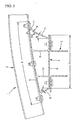
- Fig. 3 and Fig. 4 show plastic deformation of the bumper reinforcement 2 and a state of displacing the inner side rib 7 of the bumper stay 4 when an impact force F by collision is operated to the bumper reinforcement.
- the impact force F is received by the wide crash range l 1 and the bumper reinforcement 2 is plastically deformed in the wide range in the width direction of the vehicle.
- the stroke that means state of displacing of the bumper reinforcement 2 to the rear side can be restrained to be small, smaller than that of the prior art in the dimension between the inner side rib 7 of the left and right bumper stays 4.
- a so-to-speak offset collision The example shown in Fig. 3 and Fig. 4 is referred to as a so-to-speak offset collision and the bumper apparatus is collided with a rigid barrier 12 at a low speed (assumed to be 8km/h of speed per hour).
- the projected portion 11 of the inner side rib 7 is displaced to the inner side to restrict an onset of buckling of the inner side rib 7 (A direction shown in Fig. 5).
- a buckling direction of the inner side rib 7 is restricted to a side of the middle rib 9 (inner side of section) and as shown by Fig. 4, the inner side rib 7 is displaced in B direction shown in Fig. 5.
- the deformation enables to input an equally distributed load to four pieces of the ribs 7, 8, 9, 10 and absorb the impact energy by equally distributed buckling.
- a component f 2 of the impact force F operated to the middle rib 9 is operated in an axis center direction of buckling the middle rib 9
- a component f 1 of the impact force F operated to the inner side rib is inputted to the inner side rib 7 from a skewed direction to displace the projected portion 11 in the arrow mark A direction.
- the movement of the projected portion 11 enables to finally displace the remaining portion of the inner side rib 7 in the arrow mark B direction, form the inner side rib 7 in a shape proximate to erection, bring the middle rib 9 and the inner side rib 7 into substantially a parallel relationship and receive the component f 1 in an axis line direction of the inner side rib 7, that is, as buckling load.
- the components f 1 , f 2 ... become substantially uniformly operated to the respective ribs and support wide plastic deformation of the bumper reinforcement 2.
- the bumper stay 4 having the shape shown in Fig. 1 is constituted by an extruded member of an aluminum based alloy material of 7003S-T5.
- An average plate thickness is constituted by 2.5mm, however, the plate thickness of the inner side rib 7 is constituted by 2.8mm, l 1 is constituted by 200mm, l 2 is constituted by 70mm, R is constituted by 20mm, ⁇ 1 is constituted by 25° and ⁇ 2 is constituted by 75°.
- FIG. 6 A result thereof is shown in Fig. 6. According to the example of the invention, it has been confirmed that the stroke is reduced by 20% and the load is increased by a multiplication factor of 1.27. Further, it can be confirmed that the crash range of the bumper reinforcement of the example of the invention is increased.
- the impact force test is carried out also with regard to the shape shown in Fig. 1 which is not provided with the projected portion 11 under a condition the same as the above-described. As shown by Fig. 6, damage of the body is recognized by exceeding a body resistance and effectiveness of the projected portion has been confirmed.
Landscapes
- Engineering & Computer Science (AREA)
- Mechanical Engineering (AREA)
- Body Structure For Vehicles (AREA)
- Vibration Dampers (AREA)
Abstract
Description
Claims (6)
- A bumper apparatus comprising a bumper apparatus including a bumper reinforcement extended in a width direction of a vehicle and a bumper stay fixed to a side member on a side of a vehicle body, wherein the bumper stay includes a front wall portion fixed to the bumper reinforcement, a rear wall portion fixed to the side member on the side of the vehicle body, and a plurality of ribs for coupling the two wall portions and the inner and the outer side ribs are provided with an angle of inclination diverging to a front side, the inner side rib includes a projected portion projected to an inner side and a dimension in a width direction of the front wall portion is larger than a dimension in a width direction of the rear wall portion.
- The bumper apparatus according to Claim 1, wherein a single one of the projected portion is provided on a side of the bumper reinforcement of inner side rib.
- The bumper apparatus according to Claim 2, wherein an opening angle 2 of the projected portion falls in a range of 45° through 120°.
- The bumper apparatus according to Claim 2 or 3, wherein the bumper stay is a pressed product of one sheet of a steel plate and a hollow portion between the respective ribs is opened to a front side or a rear side.
- The bumper apparatus according to Claim 2 or 3, wherein the bumper stay comprises an extruded member of an aluminum based alloymaterial and three pieces of closed hollow portions thereof are partitioned between the front and the rear wall portions by the ribs.
- The bumper apparatus according to Claim 5, wherein a length of the outer side rib is smaller than a length of the inner side rib.
Applications Claiming Priority (3)
| Application Number | Priority Date | Filing Date | Title |
|---|---|---|---|
| JP2002116953 | 2002-04-19 | ||
| JP2002116953A JP3869748B2 (en) | 2002-04-19 | 2002-04-19 | Bumper equipment |
| PCT/JP2003/005035 WO2003089275A1 (en) | 2002-04-19 | 2003-04-21 | Bumper device |
Publications (3)
| Publication Number | Publication Date |
|---|---|
| EP1498319A1 true EP1498319A1 (en) | 2005-01-19 |
| EP1498319A4 EP1498319A4 (en) | 2007-01-03 |
| EP1498319B1 EP1498319B1 (en) | 2012-08-15 |
Family
ID=29243475
Family Applications (1)
| Application Number | Title | Priority Date | Filing Date |
|---|---|---|---|
| EP03723152A Expired - Lifetime EP1498319B1 (en) | 2002-04-19 | 2003-04-21 | Bumper device |
Country Status (6)
| Country | Link |
|---|---|
| US (1) | US7000975B2 (en) |
| EP (1) | EP1498319B1 (en) |
| JP (1) | JP3869748B2 (en) |
| KR (1) | KR20040097174A (en) |
| CN (1) | CN1313300C (en) |
| WO (1) | WO2003089275A1 (en) |
Cited By (2)
| Publication number | Priority date | Publication date | Assignee | Title |
|---|---|---|---|---|
| DE102005003598A1 (en) * | 2005-01-25 | 2006-08-03 | Suspa Holding Gmbh | Protection device for motor vehicle, has connecting unit provided with bending units at cross beam and deformation body, such that length of freely lying reference-bending section is greater than distance between two fastening sections |
| CN101965278B (en) * | 2008-03-05 | 2014-02-26 | 日轻金Act株式会社 | Bumper structure |
Families Citing this family (35)
| Publication number | Priority date | Publication date | Assignee | Title |
|---|---|---|---|---|
| JP4114468B2 (en) * | 2002-12-05 | 2008-07-09 | トヨタ自動車株式会社 | Bumper support structure for vehicles |
| DE10314021A1 (en) * | 2003-03-28 | 2004-10-21 | Daimlerchrysler Ag | Bumper bar/fender for a motor vehicle has bumper bar/fender outer and inner parts, a base part and a side stay so as to change shape during collisions |
| JP2005205991A (en) * | 2004-01-21 | 2005-08-04 | Honda Motor Co Ltd | Bumper beam structure |
| JP2005271858A (en) * | 2004-03-26 | 2005-10-06 | Aisin Seiki Co Ltd | Bumper device for vehicle |
| US7658421B2 (en) * | 2004-04-27 | 2010-02-09 | Kabushiki Kaisha Kobe Seiko Sho | Axial member with flange, connection member and production methods thereof |
| US6988753B1 (en) * | 2004-07-20 | 2006-01-24 | Honda Motor Co., Ltd. | Bumper beam attachment structure for vehicle |
| JP3962040B2 (en) * | 2004-07-20 | 2007-08-22 | 本田技研工業株式会社 | Bumper beam mounting structure for vehicles |
| JP2006347527A (en) * | 2004-11-24 | 2006-12-28 | Kobe Steel Ltd | Bumper device and bumper stay |
| JP4433474B2 (en) * | 2005-02-21 | 2010-03-17 | 本田技研工業株式会社 | Bumper beam mounting structure for vehicles |
| KR100579875B1 (en) | 2005-05-12 | 2006-05-12 | 현대모비스 주식회사 | Bumper Stays and Automotive Bumper Assemblies |
| JP4723948B2 (en) * | 2005-08-05 | 2011-07-13 | アイシン精機株式会社 | Bumperin force for vehicles |
| US20070039282A1 (en) * | 2005-08-19 | 2007-02-22 | Christian Holl | Gooseneck beam |
| JP2007261427A (en) * | 2006-03-28 | 2007-10-11 | Nikkeikin Aluminium Core Technology Co Ltd | Bumper structure |
| JP5204388B2 (en) * | 2006-08-31 | 2013-06-05 | 株式会社神戸製鋼所 | Energy absorbing member made of extruded aluminum alloy |
| JP4759497B2 (en) * | 2006-11-29 | 2011-08-31 | 東海ゴム工業株式会社 | Shock absorber for automobile |
| JP4706656B2 (en) * | 2007-03-30 | 2011-06-22 | 日本軽金属株式会社 | Bumpy stay |
| JP5217574B2 (en) * | 2008-04-01 | 2013-06-19 | 日産自動車株式会社 | Bumper mounting structure |
| US7866716B2 (en) * | 2008-04-08 | 2011-01-11 | Flex-N-Gate Corporation | Energy absorber for vehicle |
| DE102010006977A1 (en) * | 2010-02-05 | 2011-08-11 | GM Global Technology Operations LLC, ( n. d. Ges. d. Staates Delaware ), Mich. | Motor vehicle front end |
| DE102010006975A1 (en) * | 2010-02-05 | 2011-08-11 | GM Global Technology Operations LLC, ( n. d. Ges. d. Staates Delaware ), Mich. | Motor vehicle front end |
| DE102010006978A1 (en) * | 2010-02-05 | 2011-08-11 | GM Global Technology Operations LLC, ( n. d. Ges. d. Staates Delaware ), Mich. | Bumper arrangement for a motor vehicle |
| DE102010024572A1 (en) | 2010-06-22 | 2011-12-22 | Gm Global Technology Operations Llc (N.D.Ges.D. Staates Delaware) | Impact damping structure with crash boxes |
| KR20120062217A (en) * | 2010-12-06 | 2012-06-14 | 현대자동차주식회사 | Crash Box of Car Bumper |
| JP6153035B2 (en) * | 2012-02-03 | 2017-06-28 | マグナ インターナショナル インコーポレイテッド | Crash box for bumper assembly |
| JP5837446B2 (en) * | 2012-03-14 | 2015-12-24 | アイシン精機株式会社 | Crash box and bumper device |
| KR101316876B1 (en) | 2012-07-03 | 2013-10-08 | 기아자동차주식회사 | Bumper assembly for vehicle |
| JP2014141179A (en) * | 2013-01-24 | 2014-08-07 | Aisin Seiki Co Ltd | Shock absorber |
| DE102013007348A1 (en) * | 2013-04-27 | 2014-10-30 | GM Global Technology Operations LLC (n. d. Gesetzen des Staates Delaware) | Bumper assembly and method for its manufacture |
| KR101601428B1 (en) * | 2014-06-03 | 2016-03-09 | 현대자동차주식회사 | Crash box for vehicle |
| US9415735B1 (en) * | 2015-09-11 | 2016-08-16 | Ford Global Technologies, Llc | Vehicle deflection system for impact events |
| DE102015117005A1 (en) * | 2015-10-06 | 2017-04-06 | Benteler Automobiltechnik Gmbh | crash box |
| US10065587B2 (en) | 2015-11-23 | 2018-09-04 | Flex|N|Gate Corporation | Multi-layer energy absorber |
| JP6834885B2 (en) * | 2017-09-27 | 2021-02-24 | トヨタ自動車株式会社 | Body structure |
| DE102018114174B4 (en) * | 2018-06-13 | 2022-08-25 | Benteler Automobiltechnik Gmbh | bumper system |
| US20240399990A1 (en) * | 2023-05-30 | 2024-12-05 | Shape Corp. | Roll-formed vehicle reinforcement beam |
Family Cites Families (12)
| Publication number | Priority date | Publication date | Assignee | Title |
|---|---|---|---|---|
| DE2149035C2 (en) * | 1971-10-01 | 1986-01-02 | Daimler-Benz Ag, 7000 Stuttgart | Bracket for a bumper of vehicles, in particular motor vehicles |
| US4413856A (en) * | 1981-08-07 | 1983-11-08 | General Motors Corporation | Hardbar energy absorbing bumper system for vehicles |
| JP3380339B2 (en) | 1994-10-07 | 2003-02-24 | 三菱アルミニウム株式会社 | Automotive bumper mounting bracket |
| GB9507246D0 (en) * | 1995-04-07 | 1995-05-31 | Rover Group | A motor vehicle |
| GB2307665B (en) * | 1995-11-30 | 1999-04-14 | Rover Group | An impact absorbing structure for a motor vehicle |
| JP3550999B2 (en) * | 1998-01-20 | 2004-08-04 | 日産自動車株式会社 | Vehicle bumper mounting structure |
| JP3938451B2 (en) | 1999-10-18 | 2007-06-27 | 関東自動車工業株式会社 | Energy absorbing member |
| DE19962817A1 (en) * | 1999-12-23 | 2001-06-28 | Mannesmann Vdo Ag | Electronic device |
| JP4009404B2 (en) | 2000-04-11 | 2007-11-14 | 株式会社神戸製鋼所 | Bumper reinforcement with stay |
| JP4232327B2 (en) * | 2000-07-03 | 2009-03-04 | 日本軽金属株式会社 | Bumpy stay |
| JP4362952B2 (en) | 2000-07-03 | 2009-11-11 | 日本軽金属株式会社 | Bumpy stay |
| JP2002067840A (en) * | 2000-09-05 | 2002-03-08 | Toyota Auto Body Co Ltd | Bumber reinforcement structure |
-
2002
- 2002-04-19 JP JP2002116953A patent/JP3869748B2/en not_active Expired - Fee Related
-
2003
- 2003-04-21 CN CNB038088436A patent/CN1313300C/en not_active Expired - Fee Related
- 2003-04-21 US US10/509,761 patent/US7000975B2/en not_active Expired - Lifetime
- 2003-04-21 WO PCT/JP2003/005035 patent/WO2003089275A1/en not_active Ceased
- 2003-04-21 KR KR10-2004-7014443A patent/KR20040097174A/en not_active Withdrawn
- 2003-04-21 EP EP03723152A patent/EP1498319B1/en not_active Expired - Lifetime
Cited By (2)
| Publication number | Priority date | Publication date | Assignee | Title |
|---|---|---|---|---|
| DE102005003598A1 (en) * | 2005-01-25 | 2006-08-03 | Suspa Holding Gmbh | Protection device for motor vehicle, has connecting unit provided with bending units at cross beam and deformation body, such that length of freely lying reference-bending section is greater than distance between two fastening sections |
| CN101965278B (en) * | 2008-03-05 | 2014-02-26 | 日轻金Act株式会社 | Bumper structure |
Also Published As
| Publication number | Publication date |
|---|---|
| JP3869748B2 (en) | 2007-01-17 |
| CN1646345A (en) | 2005-07-27 |
| JP2003312399A (en) | 2003-11-06 |
| EP1498319A4 (en) | 2007-01-03 |
| KR20040097174A (en) | 2004-11-17 |
| WO2003089275A1 (en) | 2003-10-30 |
| EP1498319B1 (en) | 2012-08-15 |
| CN1313300C (en) | 2007-05-02 |
| US7000975B2 (en) | 2006-02-21 |
| US20050104393A1 (en) | 2005-05-19 |
Similar Documents
| Publication | Publication Date | Title |
|---|---|---|
| EP1498319B1 (en) | Bumper device | |
| EP1219499B1 (en) | Coupling structure of bumper reinforce and shock absorbing member | |
| US7931318B2 (en) | Bumper attachment portion structure | |
| EP2412583A1 (en) | Impact absorbing device for vehicle and bumper device for vehicle | |
| US9539965B2 (en) | Bumper moment inducer | |
| JP5501892B2 (en) | Vehicle tow hook mounting structure | |
| CN101965278A (en) | Bumper structure | |
| US5378021A (en) | Collapsible steering column apparatus | |
| EP1389575B1 (en) | Vehicle front-end body structure | |
| EP1852331B1 (en) | Front structure of vehicle body | |
| JP4996690B2 (en) | Bumper structure | |
| CN219544705U (en) | Anti-collision beam, anti-collision beam assembly and vehicle | |
| US20020060463A1 (en) | Shock absorbing member and bumper | |
| JP2008094262A (en) | Vehicle front shock-absorbing structure | |
| JP2005067527A (en) | Automotive bumper equipment | |
| JP2005104235A (en) | Automotive bumper equipment | |
| CN205652087U (en) | A bumper system and vehicle for vehicle | |
| JPH0781504A (en) | Bumper form member | |
| JP2018111378A (en) | Vehicle bumper structure | |
| JP2002166799A (en) | Buffer structure for collision of bumper reinforce on vehicle body | |
| JP7740919B2 (en) | Vehicle front structure | |
| JP2005162027A (en) | Energy absorption structure for vehicles | |
| JP2009196544A (en) | Front side member structure | |
| EP1295781A2 (en) | A structural member for a motor vehicle | |
| CN108263320A (en) | Energy-absorbing case assembly and anticollision device, collision-prevention device |
Legal Events
| Date | Code | Title | Description |
|---|---|---|---|
| PUAI | Public reference made under article 153(3) epc to a published international application that has entered the european phase |
Free format text: ORIGINAL CODE: 0009012 |
|
| 17P | Request for examination filed |
Effective date: 20040916 |
|
| AK | Designated contracting states |
Kind code of ref document: A1 Designated state(s): AT BE BG CH CY CZ DE DK EE ES FI FR GB GR HU IE IT LI LU MC NL PT RO SE SI SK TR |
|
| A4 | Supplementary search report drawn up and despatched |
Effective date: 20061204 |
|
| RIC1 | Information provided on ipc code assigned before grant |
Ipc: B60R 19/26 20060101AFI20061128BHEP |
|
| 17Q | First examination report despatched |
Effective date: 20080424 |
|
| GRAC | Information related to communication of intention to grant a patent modified |
Free format text: ORIGINAL CODE: EPIDOSCIGR1 |
|
| GRAP | Despatch of communication of intention to grant a patent |
Free format text: ORIGINAL CODE: EPIDOSNIGR1 |
|
| GRAS | Grant fee paid |
Free format text: ORIGINAL CODE: EPIDOSNIGR3 |
|
| GRAA | (expected) grant |
Free format text: ORIGINAL CODE: 0009210 |
|
| AK | Designated contracting states |
Kind code of ref document: B1 Designated state(s): DE FR GB |
|
| REG | Reference to a national code |
Ref country code: GB Ref legal event code: FG4D |
|
| REG | Reference to a national code |
Ref country code: DE Ref legal event code: R096 Ref document number: 60341825 Country of ref document: DE Effective date: 20121011 |
|
| REG | Reference to a national code |
Ref country code: DE Ref legal event code: R084 Ref document number: 60341825 Country of ref document: DE Effective date: 20130306 |
|
| PLBE | No opposition filed within time limit |
Free format text: ORIGINAL CODE: 0009261 |
|
| STAA | Information on the status of an ep patent application or granted ep patent |
Free format text: STATUS: NO OPPOSITION FILED WITHIN TIME LIMIT |
|
| 26N | No opposition filed |
Effective date: 20130516 |
|
| REG | Reference to a national code |
Ref country code: DE Ref legal event code: R097 Ref document number: 60341825 Country of ref document: DE Effective date: 20130516 |
|
| GBPC | Gb: european patent ceased through non-payment of renewal fee |
Effective date: 20130421 |
|
| PG25 | Lapsed in a contracting state [announced via postgrant information from national office to epo] |
Ref country code: GB Free format text: LAPSE BECAUSE OF NON-PAYMENT OF DUE FEES Effective date: 20130421 |
|
| PGFP | Annual fee paid to national office [announced via postgrant information from national office to epo] |
Ref country code: FR Payment date: 20140409 Year of fee payment: 12 Ref country code: DE Payment date: 20140430 Year of fee payment: 12 |
|
| REG | Reference to a national code |
Ref country code: DE Ref legal event code: R119 Ref document number: 60341825 Country of ref document: DE |
|
| PG25 | Lapsed in a contracting state [announced via postgrant information from national office to epo] |
Ref country code: DE Free format text: LAPSE BECAUSE OF NON-PAYMENT OF DUE FEES Effective date: 20151103 |
|
| REG | Reference to a national code |
Ref country code: FR Ref legal event code: ST Effective date: 20151231 |
|
| PG25 | Lapsed in a contracting state [announced via postgrant information from national office to epo] |
Ref country code: FR Free format text: LAPSE BECAUSE OF NON-PAYMENT OF DUE FEES Effective date: 20150430 |