EP1497603B1 - Inverted lid sealing plate for heat exchanger - Google Patents
Inverted lid sealing plate for heat exchanger Download PDFInfo
- Publication number
- EP1497603B1 EP1497603B1 EP03717071A EP03717071A EP1497603B1 EP 1497603 B1 EP1497603 B1 EP 1497603B1 EP 03717071 A EP03717071 A EP 03717071A EP 03717071 A EP03717071 A EP 03717071A EP 1497603 B1 EP1497603 B1 EP 1497603B1
- Authority
- EP
- European Patent Office
- Prior art keywords
- heat exchanger
- plate
- fluid
- plates
- peripheral flange
- Prior art date
- Legal status (The legal status is an assumption and is not a legal conclusion. Google has not performed a legal analysis and makes no representation as to the accuracy of the status listed.)
- Expired - Lifetime
Links
- 238000007789 sealing Methods 0.000 title 1
- 239000012530 fluid Substances 0.000 claims abstract description 109
- 230000003014 reinforcing effect Effects 0.000 claims abstract description 32
- 230000002093 peripheral effect Effects 0.000 claims abstract description 31
- 238000004891 communication Methods 0.000 claims abstract description 9
- 238000012360 testing method Methods 0.000 claims description 4
- 230000003416 augmentation Effects 0.000 claims description 2
- 230000000007 visual effect Effects 0.000 claims description 2
- 238000012790 confirmation Methods 0.000 claims 2
- 230000003190 augmentative effect Effects 0.000 claims 1
- 239000000463 material Substances 0.000 description 5
- 208000027418 Wounds and injury Diseases 0.000 description 2
- 238000005219 brazing Methods 0.000 description 2
- 230000006378 damage Effects 0.000 description 2
- 208000014674 injury Diseases 0.000 description 2
- 229910000838 Al alloy Inorganic materials 0.000 description 1
- 229910000881 Cu alloy Inorganic materials 0.000 description 1
- 230000004075 alteration Effects 0.000 description 1
- XAGFODPZIPBFFR-UHFFFAOYSA-N aluminium Chemical compound [Al] XAGFODPZIPBFFR-UHFFFAOYSA-N 0.000 description 1
- 229910052782 aluminium Inorganic materials 0.000 description 1
- 230000004888 barrier function Effects 0.000 description 1
- 238000010276 construction Methods 0.000 description 1
- 210000001503 joint Anatomy 0.000 description 1
- 238000000034 method Methods 0.000 description 1
- 238000012986 modification Methods 0.000 description 1
- 230000004048 modification Effects 0.000 description 1
- 230000008569 process Effects 0.000 description 1
- 239000010935 stainless steel Substances 0.000 description 1
- 229910001256 stainless steel alloy Inorganic materials 0.000 description 1
- 239000000126 substance Substances 0.000 description 1
- 238000012546 transfer Methods 0.000 description 1
- 238000012795 verification Methods 0.000 description 1
Images



Classifications
-
- F—MECHANICAL ENGINEERING; LIGHTING; HEATING; WEAPONS; BLASTING
- F28—HEAT EXCHANGE IN GENERAL
- F28F—DETAILS OF HEAT-EXCHANGE AND HEAT-TRANSFER APPARATUS, OF GENERAL APPLICATION
- F28F9/00—Casings; Header boxes; Auxiliary supports for elements; Auxiliary members within casings
- F28F9/02—Header boxes; End plates
- F28F9/026—Header boxes; End plates with static flow control means, e.g. with means for uniformly distributing heat exchange media into conduits
-
- F—MECHANICAL ENGINEERING; LIGHTING; HEATING; WEAPONS; BLASTING
- F28—HEAT EXCHANGE IN GENERAL
- F28D—HEAT-EXCHANGE APPARATUS, NOT PROVIDED FOR IN ANOTHER SUBCLASS, IN WHICH THE HEAT-EXCHANGE MEDIA DO NOT COME INTO DIRECT CONTACT
- F28D9/00—Heat-exchange apparatus having stationary plate-like or laminated conduit assemblies for both heat-exchange media, the media being in contact with different sides of a conduit wall
- F28D9/0031—Heat-exchange apparatus having stationary plate-like or laminated conduit assemblies for both heat-exchange media, the media being in contact with different sides of a conduit wall the conduits for one heat-exchange medium being formed by paired plates touching each other
- F28D9/0043—Heat-exchange apparatus having stationary plate-like or laminated conduit assemblies for both heat-exchange media, the media being in contact with different sides of a conduit wall the conduits for one heat-exchange medium being formed by paired plates touching each other the plates having openings therein for circulation of at least one heat-exchange medium from one conduit to another
- F28D9/005—Heat-exchange apparatus having stationary plate-like or laminated conduit assemblies for both heat-exchange media, the media being in contact with different sides of a conduit wall the conduits for one heat-exchange medium being formed by paired plates touching each other the plates having openings therein for circulation of at least one heat-exchange medium from one conduit to another the plates having openings therein for both heat-exchange media
-
- F—MECHANICAL ENGINEERING; LIGHTING; HEATING; WEAPONS; BLASTING
- F28—HEAT EXCHANGE IN GENERAL
- F28F—DETAILS OF HEAT-EXCHANGE AND HEAT-TRANSFER APPARATUS, OF GENERAL APPLICATION
- F28F3/00—Plate-like or laminated elements; Assemblies of plate-like or laminated elements
- F28F3/02—Elements or assemblies thereof with means for increasing heat-transfer area, e.g. with fins, with recesses, with corrugations
- F28F3/025—Elements or assemblies thereof with means for increasing heat-transfer area, e.g. with fins, with recesses, with corrugations the means being corrugated, plate-like elements
- F28F3/027—Elements or assemblies thereof with means for increasing heat-transfer area, e.g. with fins, with recesses, with corrugations the means being corrugated, plate-like elements with openings, e.g. louvered corrugated fins; Assemblies of corrugated strips
-
- F—MECHANICAL ENGINEERING; LIGHTING; HEATING; WEAPONS; BLASTING
- F28—HEAT EXCHANGE IN GENERAL
- F28F—DETAILS OF HEAT-EXCHANGE AND HEAT-TRANSFER APPARATUS, OF GENERAL APPLICATION
- F28F2225/00—Reinforcing means
- F28F2225/04—Reinforcing means for conduits
-
- F—MECHANICAL ENGINEERING; LIGHTING; HEATING; WEAPONS; BLASTING
- F28—HEAT EXCHANGE IN GENERAL
- F28F—DETAILS OF HEAT-EXCHANGE AND HEAT-TRANSFER APPARATUS, OF GENERAL APPLICATION
- F28F2280/00—Mounting arrangements; Arrangements for facilitating assembling or disassembling of heat exchanger parts
- F28F2280/04—Means for preventing wrong assembling of parts
-
- Y—GENERAL TAGGING OF NEW TECHNOLOGICAL DEVELOPMENTS; GENERAL TAGGING OF CROSS-SECTIONAL TECHNOLOGIES SPANNING OVER SEVERAL SECTIONS OF THE IPC; TECHNICAL SUBJECTS COVERED BY FORMER USPC CROSS-REFERENCE ART COLLECTIONS [XRACs] AND DIGESTS
- Y10—TECHNICAL SUBJECTS COVERED BY FORMER USPC
- Y10S—TECHNICAL SUBJECTS COVERED BY FORMER USPC CROSS-REFERENCE ART COLLECTIONS [XRACs] AND DIGESTS
- Y10S165/00—Heat exchange
- Y10S165/916—Oil cooler
Definitions
- This invention relates to heat exchangers of the type formed from dish-shaped heat exchanger plates.
- plate-type heat exchangers includes a plurality of plates secured together in a stacked assembly with gaskets or bosses located between adjacent plates and traversing a course adjacent to the plate peripheries. Flow of two fluids involved in heat exchange is through alternate layers defined by the stacked plates. The stacked plates are typically joined together as a unitary structure by brazing the various components together. Examples of such plate-type heat exchangers are disclosed, for example, in U.S. Patent No. 5,931,219 issued to Kull et al. and U.S. Patent No. 4,872,578 issued to Fuerschbach et al.
- a characteristic of previously proposed nested-dish heat exchangers is that in order to provide strength to the heat exchanger stack, the heat exchanger plates are typically sandwiched between a pair of thicker end plates.
- One of the end plates is typically nested within the flange of the final plate in the stack of the heat exchanger plates with the peripheral flange of the final heat exchanger plate extending a substantial distance beyond an outer surface of such end plate.
- Such a configuration can result in wasted space, namely, the area surrounded by the portion of the peripheral flange on the final heat exchanger plate that extends beyond the outer surface of the end plate.
- the extending flange edge can provide a sharp edge such that care must be used in handling the heat exchanger to avoid injury to the person handling the heat exchanger. Accordingly, there is a need for a nested dish plate-type heat exchanger that reduces unused space.
- a plate-type heat exchanger which reduces the exposed peripheral flange of the final heat exchanger plate in the stack of plates is also desired
- an inverted dish-type end plate configuration is used so that a fluid flow channel can be located between the end plate and the final heat-exchanger plate in the stack of heat exchanger plates, thereby reducing unused space in the stack and reducing the extent to which the flange on the final nested dish heat exchanger plate is exposed.
- a heat exchanger characterized by a first heat exchanger plate having a central planer portion and a peripheral flange projecting therefrom, and an end plate having a central planar portion and a peripheral flange projecting therefrom, the peripheral flange of the end plate projecting in an opposite direction than and sealably nested within the peripheral flange of the first heat exchanger plate, a fluid channel being located between the central planar portions of the first heat exchanger and end plates.
- a stacked plate-type heat exchanger including a plurality of dish- shaped heat exchanger plates arranged one next to the other to form a nested heat exchanger plate stack, each of the heat exchanger plates having a planar central portion with a peripheral flange projecting therefrom, a plurality of first and second fluid flow channels formed between the heat exchanger plates for first and second fluids respectively.
- the heat exchanger has first fluid and second fluid chambers formed in the stack in communication with the first and second fluid channels respectively, and includes an end plate with an end plate central planar portion and a peripheral flange projecting from the end plate central planar portion, the peripheral flange of the end plate projecting in an opposite direction and sealably nested within the peripheral flange of a final heat exchanger plate in the plate stack.
- a planar reinforcing plate is secured to an inner surface of end plate central planar portion between the end plate central planar portion and the final heat exchanger plate, a further fluid channel for one of the first and second fluids being located between the planar reinforcing plate and the final heat exchanger plate.
- a stacked plate-type heat exchanger including a plurality of heat exchanger plates sealably secured together to form a stack, each of the heat exchanger plates having a planar central portion and inlet and outlet passages for fluid passage, a plurality of fluid channels being defined between the planar central portions, some of the fluid channels being channels for a first fluid and some of the fluid channels being channels for a second fluid to facilitate heat exchange between the first and second fluids, at least a final heat exchanger plate in the stack having a peripheral flange projecting from the planar central portion thereof.
- the heat exchanger has an end plate having an end plate central planar portion and a peripheral flange projecting from the end plate central planar portion, the peripheral flange of the end plate projecting in an opposite direction and sealably located within and secured to the peripheral flange of the final heat exchanger plate, a further fluid channel for one of the first and second fluids being located between the end plate and the final heat exchanger plate.
- FIG. 1 an exploded perspective view of a preferred embodiment of a stacked-plate type heat exchanger according to the present invention is generally indicated by reference number 10.
- the heat exchanger 10 includes an end plate 12, a reinforcing plate 14, a number of alternating nested dish plates 16 and 18, and a connector plate 20. Plates 12 through 20 are shown arranged vertically in Figure 1 , but this is only for the purposes of illustration.
- the heat exchanger 10 can have any orientation desired.
- the plates 12-20 are each formed from braze clad aluminum or aluminum alloy, however, other materials such as stainless steel or copper alloy, for example, could also be used.
- the dish-style heat exchanger plates 16 and 18 are alternatively stacked one next to the other to form a core heat exchanger stack 24.
- first fluid flow channels 26 and second fluid flow channels 28 for respective first and second fluids are alternatively defined between the heat exchanger plates 16 and 18 throughout the core stack 24.
- a final fluid flow channel 30 is defined between the reinforcing plate 14 and the final dish heat exchanger plate 16 (which is the top heat exchanger plate 16 shown in the Figures).
- Turbulizer plates 22, which in the illustrated embodiment includes offset rows of convolutions, are located in the flow channels 26, 28 and 30 to augment the flow of fluids therethrough and also provide support to the adjacent plates.
- the heat exchanger plate 18 shown in Figures 4 and 5 includes a rectangular planar central portion 32 having an integral, peripheral, upwardly extending flange 34.
- the flange 34 defines an angle of slightly greater than 90° with respect to the planar central portion 32.
- First and second flow openings 36 and 38 pass through the planar central portion 32, one of which functions as a first fluid inlet passage and the other of which functions as a first fluid outlet passage.
- the flow openings 36 and 38 are diagonally located relative to each other near diagonally opposite edges of the planar portion 32, as illustrated in Figure 4 .
- the flow openings 36, 38 could also be located in different locations; for example, they could both be located the same distance from a common edge, of the plate.
- the heat exchanger plate. 18 also includes raised first and second bosses 40, 42 that are integrally formed with the planar central portion 32.
- Each of the bosses 40, 42 includes an annular wall 44 that terminates at an annular support portion 46.
- the annular support portion 46 of the first boss 40 defines an opening 48 that communicates with a flow passage 50 that is defined by the annular wall 44 of the boss 40.
- the annular support portion 46 of the second boss 42 defines an opening 52 that communicates with a flow passage defined by the annular wall 44 of the boss 42.
- the alternating heat exchanger plates 16 are substantially identical to heat exchanger plates 18 and thus each include, with reference to Figure 6 , a planar central portion 54, first and second flow openings 58, 60, respectively, and first and second bosses 62 and 64, respectively, each of which define a flow opening 66 and 68, respectively. Integral peripheral flange 70 extends from the planar central portion 54.
- Heat exchange plates 16 and 18 are, in a preferred embodiment, identical with the one exception that the locations of the bosses and flow openings are reversed between the plates 16 and 18, as is readably apparent from a comparison of Figures 4 and 6 .
- the first boss 40 on plate 18 is located in a position corresponding to the location of the first flow opening 58 in alternative plate 16.
- the second boss 42 on plate 18 is located in a position corresponding to the location of the second flow opening 60 through alternative plate 16.
- the first flow opening 36 through plate 18 is located in a position corresponding to the location of the first boss 62 through alternating plate 16
- the second flow opening 38 through plate 18 is located in a position corresponding to the location of the second boss 64 of alternating plate 16.
- the flow openings 36 and 38 (and corresponding bosses) need not be diagonally located, but could be for example longitudinally located on the plate relative to each other.
- the end plate 12 includes a planar central end plate portion 72 that is surrounded by integral, peripheral, downwardly extending flange 74.
- the reinforcing plate 14 is a substantially planar member that has a size substantially close to that of the planar central end plate portion 72, and which is nested within flange 74.
- an error proofing hole 76 is preferably provided through the planar central end plate portion 72.
- the central planar portions of plates 12, 16 and 18 are each formed from material of the same thickness, with reinforcing plate 14 being formed from a thicker material sufficient to provide necessary strength for the final flow channel.
- the core stack 24 sits on a connector plate 20, which will typically be made of thicker material than the planar portions of plates 12, 16 and 18.
- the connector plate 20 has a footprint that corresponds largely to the central planar portion 32 of the first heat exchanger plate (which in Figure 2 is the bottom plate 18) in the core stack 24.
- Connector plate 20 has first fluid first and second ports 78 and 82 formed therethrough, one of which functions as a first fluid inlet port, and the other of which functions as a first fluid outlet port for the heat exchanger 10.
- the connector plate 20 also has formed therethrough second fluid first and second ports 80 and 84, one of which functions as a fluid inlet port and the other of which functions as a fluid outlet port for the second fluid used in heat exchanger 10.
- the connector plate 20 may include one or more laterally extending connector portions 86 that have openings formed therethrough to permit the heat exchanger 10 to be secured or mounted in place.
- the core stack 24 is made up of alternating stacked dish-style heat exchanger plates 16 and 18. As best seen in Figure 3 , an outer lower portion of the flange 70 of each heat exchanger plate 16 is received within an inner upper portion of the flange 34 of an adjacent lower heat exchanger plate 18. Similarly, each heat exchanger plate 18 (with the exception of the first heat exchanger plate 18 in the stack 24) has a lower outer portion of its flange 34 received within an upper inner portion of the flange 70 of an adjacent lower heat exchanger plate 16.
- the flanges of the heat exchanger plates 16, 18 each receive and support (with the exception of the top or end heat exchanger plate 16 in the stack 24) an adjacent heat exchanger plate 18, 16, respectively.
- the bosses 40, 42, 62 and 64 and the turbulizer plates 22 located between the plates provide further support for the plates.
- the first fluid flow channels 26 are defined between the bottom surfaces of the central planar portions 54 of heat exchanger plates 16 and the upper surfaces of the central planar portions 32 of the heat exchanger plates 18.
- the second fluid flow channels 28 are defined between an upper surface of the central planar portion 54 of the heat exchanger plate 16 and the lower surfaces of the central planar portions 32 of the heat exchanger plates 18.
- the first fluid first port 78 through connector plate 20, the first flow openings 36 through the plates 18, and the openings 68 through the first bosses 62 of the alternating heat exchanger plates 16 are all in alignment with each other thereby providing a first fluid flow chamber for the first fluid, indicated by phantom line 88 in Figure 2 , that is in flow communication with each of the first fluid flow channels 26.
- the annular wall 44 and planar support portion 46 of each of the first bosses 62 of the heat exchanger plates 16 isolate the second fluid flow channels 28 from the first fluid flow chamber 88.
- annular walls 44 and planar support portions 46 of each of the bosses 62 are sized such that an upper surface of the planar support portion 46 of the boss 62 sealingly engages a bottom surface of the planar central portion of adjacent higher plate 18 about the circumference of the first flow opening 36.
- the bosses 40, 42 and 64 are each similarly configured to provide a similar function in the proximity of the other three corners of the heat exchanger stack 24.
- the second port 82 for the first fluid is aligned with the second flow openings 38 through the plates 18 and the openings 66 through the second bosses 64 in alternating plates 16 to provide a second flow chamber for the first fluid that is in communication with the first fluid flow channels 26.
- One of the first fluid flow chamber 88 and the second fluid flow chamber for the first fluid functions as an inlet chamber, and the other as an outlet chamber.
- the first port 80 for the second fluid is aligned with the openings 48 through the first bosses 40 of the heat exchanger plates 18 and the openings 58 of the plates. 16 to provide a flow chamber for the second fluid, as indicated conceptually by phantom line 90. in Figure 2 , that is in flow communication with the second fluid flow channels 28 and further flow channel 30.
- the second port 84 for the second fluid aligns with the openings 52 through the bosses 42 of plates 18 and the openings 60 of plates 16 to provide a further fluid flow chamber for the second fluid that is in communication with the fluid flow channels 28 and further flow channel 30.
- One of the fluid flow chamber 90 and the further fluid flow chamber for the second fluid functions as an inlet chamber, and the other as an outlet chamber.
- the peripheral flange 74 of the end plate 12 projects in an opposite direction than the flange 70 of the final heat exchanger plate 16 in the stack 24.
- the heat exchanger plate 12 is dimensioned so that the flange 74 can be closely received within an upper portion of the flange 70 of the final heat exchanger plate with an outer surface of the flange 74 overlapping with an inner surface of the flange 70 as illustrated in Figure 3 .
- Brazing material 92 sealably secures the flanges 70 and 74 about their respective perimeters.
- Reinforcing plate 14 is brazed to an inner surface of the end plate central planar portion 72, and to the raised boss portions of plate 16, and to the turbulizer plate 22.
- a final fluid flow channel 30 is defined between the reinforcing plate 14 and the final heat exchanger plate in the stack 24.
- the final fluid flow channel 30 is a fluid flow channel for the second fluid, however, in different configurations it could act as a flow channel for the first fluid.
- the planar support portion 46 of the boss 62 sealingly engages the reinforcing plate 14, thereby ensuring the first fluid flow chamber 88 is not in communication with the final fluid flow channel 30.
- the planar support portion of the second boss 64 of the final heat exchanger plate 16 also sealingly engages the reinforcing plate 14.
- Reinforcing plate 14 and end plate 12 provide the combined strength required to resist the pressure present at the top end of the plate stack 24.
- connector plate 20 reinforces the bottom end of the stack 24 to provide the required strength at such end.
- the combined use of an end plate 14 and reinforcing plate 12 can result in more pressure resistance than a single plate of the same thickness as the overlap joint formed between flanges 74 and 70 tends to be stronger than the butt joint that would exist if a thicker single plate were used in place of separate plates 12 and 14.
- the flange 74 projects from the inner surface of the planar central end portion 72 a distance substantially equal to the thickness of the reinforcing plate 14. Such a configuration permits the turbulizer plate 22 in the final fluid flow channel 30 to extend relatively close to inner surface of the portion of flange 70 that defines the periphery of the flow channel 30.
- the error proofing hole 76 through the end plate 12 is provided to allow error proofing to be carried out to ensure that the reinforcing plate 14 has been properly installed in the heat exchanger 10 during its assembly.
- the hole 76 is preferably large enough to allow a person to visually verify, by looking through the hole, that the reinforcing plate 14 is present.
- the hole 76 is preferably small enough so as to avoid affecting the structural integrity or strength of the end plate 12.
- the error proofing hole 76 can also provide a functional verification that the reinforcing plate 14 is sealably located in place during a test in which a test fluid under pressure is forced into the final fluid flow channel 30.
- a first fluid enters the heat exchanger 10 through port 78 and flows in parallel through the first fluid flow channels 26, and subsequently out of the heat exchanger through the port 82 in connecting plate 20.
- a second fluid enters the heat exchanger through fluid port 80, and flows in parallel through each of the second fluid flow channels 28 and the final fluid flow channel 30, and leaves the heat exchanger 10 through the fluid port 84 in connector plate 20. In such a manner, heat is exchanged between the two fluids as they flow through the alternating flow channels of the stack 24.
- the present invention provides a stacked-dish plate-type heat exchanger in which the final dish heat exchanger plate in the stack is actively used in the heat exchanging process, thereby eliminating any unused space.
- the overlapping joint between the end plate and the final dish heat exchanger plate provides a pressure resistant configuration.
- the exposed edge of the flange of the last heat exchanger plate in the stack is minimized.
- the end plate 12 is substantially flush with an upper edge of the flange 70, thereby reducing the chance of injury occurring due to a protruding flange.
- the plates have been illustrated as rectangular, however, different plate configurations could be used in conformance with the present invention, such as circular or oblong-shaped plates.
- the alternating flow channels have been illustrated as having the same height.
- the alternating plates could have different flange heights so that the alternating flow channels have correspondingly different heights.
- separate collars could be used in the place of bosses 62, 64, 40 and 42.
- the locations of the flow openings and bosses could be varied, for example, the flow openings through each plate could be longitudinally positioned relative to each other rather than diagonally located, or could be located side-by-side, separated by a barrier forcing an indirect U-shaped flow path.
- the turbulizer plates 22 could extend from end-to-end of the heat exchanger, or could terminate prior to the flow openings.
- integrally formed dimples or ribs on plates 16, 18 could be used in the place of turbulizer plates 22 for flow augmentation and structural support, and in some embodiments turbulizers 22 may be entirely omitted from some or all of the flow channels.
- the reinforcing plate may not be required so long as the end plate 12 is thick enough or otherwise sufficiently supported to withstand any pressure applied to it.
- the reinforcing plate 14 may dimpled or ribbed or be formed with rippled convolutions.
- embodiments of the heat exchanger described above have included a core stack of a plurality of dish-type plates 16,18, with a final inverted dish-type end plate 12, in some embodiments the inverted dish-type end plate 12 could be used, with or without reinforcing plate 14, and with or without a turbulizer 22, in combination with just a single dish-type plate 16 or 18 (in which case the dish-type place 16 or 18 need not have raised bosses with openings formed therethrough).
- Such a configuration could be used, for example, for a low-profile heat exchanger having a single enclosed fluid flow channel between the end plate 12 and the adjacent single dish-type plate 16 or 18.
Landscapes
- Engineering & Computer Science (AREA)
- Physics & Mathematics (AREA)
- Thermal Sciences (AREA)
- Mechanical Engineering (AREA)
- General Engineering & Computer Science (AREA)
- Heat-Exchange Devices With Radiators And Conduit Assemblies (AREA)
- Details Of Heat-Exchange And Heat-Transfer (AREA)
- Separation By Low-Temperature Treatments (AREA)
Abstract
Description
- This invention relates to heat exchangers of the type formed from dish-shaped heat exchanger plates.
- One form of plate-type heat exchangers includes a plurality of plates secured together in a stacked assembly with gaskets or bosses located between adjacent plates and traversing a course adjacent to the plate peripheries. Flow of two fluids involved in heat exchange is through alternate layers defined by the stacked plates. The stacked plates are typically joined together as a unitary structure by brazing the various components together. Examples of such plate-type heat exchangers are disclosed, for example, in
U.S. Patent No. 5,931,219 issued to Kull et al. andU.S. Patent No. 4,872,578 issued to Fuerschbach et al. - A characteristic of previously proposed nested-dish heat exchangers is that in order to provide strength to the heat exchanger stack, the heat exchanger plates are typically sandwiched between a pair of thicker end plates. One of the end plates is typically nested within the flange of the final plate in the stack of the heat exchanger plates with the peripheral flange of the final heat exchanger plate extending a substantial distance beyond an outer surface of such end plate. Such a configuration can result in wasted space, namely, the area surrounded by the portion of the peripheral flange on the final heat exchanger plate that extends beyond the outer surface of the end plate. Additionally, the extending flange edge can provide a sharp edge such that care must be used in handling the heat exchanger to avoid injury to the person handling the heat exchanger. Accordingly, there is a need for a nested dish plate-type heat exchanger that reduces unused space. A plate-type heat exchanger which reduces the exposed peripheral flange of the final heat exchanger plate in the stack of plates is also desired.
- In the present invention, an inverted dish-type end plate configuration is used so that a fluid flow channel can be located between the end plate and the final heat-exchanger plate in the stack of heat exchanger plates, thereby reducing unused space in the stack and reducing the extent to which the flange on the final nested dish heat exchanger plate is exposed.
- According to one aspect of the invention, there is provided a heat exchanger characterized by a first heat exchanger plate having a central planer portion and a peripheral flange projecting therefrom, and an end plate having a central planar portion and a peripheral flange projecting therefrom, the peripheral flange of the end plate projecting in an opposite direction than and sealably nested within the peripheral flange of the first heat exchanger plate, a fluid channel being located between the central planar portions of the first heat exchanger and end plates.
- According to another aspect of the invention, there is provided a stacked plate-type heat exchanger including a plurality of dish- shaped heat exchanger plates arranged one next to the other to form a nested heat exchanger plate stack, each of the heat exchanger plates having a planar central portion with a peripheral flange projecting therefrom, a plurality of first and second fluid flow channels formed between the heat exchanger plates for first and second fluids respectively. The heat exchanger has first fluid and second fluid chambers formed in the stack in communication with the first and second fluid channels respectively, and includes an end plate with an end plate central planar portion and a peripheral flange projecting from the end plate central planar portion, the peripheral flange of the end plate projecting in an opposite direction and sealably nested within the peripheral flange of a final heat exchanger plate in the plate stack. A planar reinforcing plate is secured to an inner surface of end plate central planar portion between the end plate central planar portion and the final heat exchanger plate, a further fluid channel for one of the first and second fluids being located between the planar reinforcing plate and the final heat exchanger plate.
- According to another aspect of the invention, there is provided a stacked plate-type heat exchanger including a plurality of heat exchanger plates sealably secured together to form a stack, each of the heat exchanger plates having a planar central portion and inlet and outlet passages for fluid passage, a plurality of fluid channels being defined between the planar central portions, some of the fluid channels being channels for a first fluid and some of the fluid channels being channels for a second fluid to facilitate heat exchange between the first and second fluids, at least a final heat exchanger plate in the stack having a peripheral flange projecting from the planar central portion thereof. The heat exchanger has an end plate having an end plate central planar portion and a peripheral flange projecting from the end plate central planar portion, the peripheral flange of the end plate projecting in an opposite direction and sealably located within and secured to the peripheral flange of the final heat exchanger plate, a further fluid channel for one of the first and second fluids being located between the end plate and the final heat exchanger plate.
- Preferred embodiments of the invention will now be described, by way of example, with reference to the accompanying drawings, throughout which like numerals are used to refer to like components.
-
Figure 1 is an exploded perspective view of a first preferred embodiment of a stacked plate-type heat exchanger made in accordance with the present invention. -
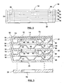
Figure 2 is a side view of the assembled heat exchanger ofFigure 1 . -
Figure 3 is an enlarged partial elevational view of the assembled heat exchanger ofFigure 1 . -
Figure 4 is a plan view of one of the heat exchanger plates used in the heat exchanger ofFigure 1 . -
Figure 5 is a sectional view taken along the lines 5-5 ofFigure 4 . -
Figure 6 is a plan view of a further heat exchanger plate used in the heat exchanger ofFigure 1 . -
Figure 7 is a plan view of an end plate of the heat exchanger ofFigure 1 . -
Figure 8 is a sectional view take along the lines 8-8 ofFigure 7 . - Referring firstly to
Figure 1 , an exploded perspective view of a preferred embodiment of a stacked-plate type heat exchanger according to the present invention is generally indicated byreference number 10. Theheat exchanger 10 includes anend plate 12, areinforcing plate 14, a number of alternatingnested dish plates connector plate 20.Plates 12 through 20 are shown arranged vertically inFigure 1 , but this is only for the purposes of illustration. Theheat exchanger 10 can have any orientation desired. - In one preferred embodiment, the plates 12-20 are each formed from braze clad aluminum or aluminum alloy, however, other materials such as stainless steel or copper alloy, for example, could also be used. With reference to
Figure 2 , the dish-styleheat exchanger plates heat exchanger stack 24. With reference toFigure 3 , firstfluid flow channels 26 and secondfluid flow channels 28 for respective first and second fluids are alternatively defined between theheat exchanger plates core stack 24. A finalfluid flow channel 30 is defined between thereinforcing plate 14 and the final dish heat exchanger plate 16 (which is the topheat exchanger plate 16 shown in the Figures).Turbulizer plates 22, which in the illustrated embodiment includes offset rows of convolutions, are located in theflow channels - With reference to
Figures 1 ,4 and 5 , the construction of dish-shapedheat exchanger plates heat exchanger plate 18 shown inFigures 4 and 5 includes a rectangular planarcentral portion 32 having an integral, peripheral, upwardly extendingflange 34. - The
flange 34 defines an angle of slightly greater than 90° with respect to the planarcentral portion 32. First andsecond flow openings central portion 32, one of which functions as a first fluid inlet passage and the other of which functions as a first fluid outlet passage. Preferably, theflow openings planar portion 32, as illustrated inFigure 4 . However, theflow openings second bosses central portion 32. Each of thebosses annular wall 44 that terminates at anannular support portion 46. Theannular support portion 46 of thefirst boss 40 defines an opening 48 that communicates with aflow passage 50 that is defined by theannular wall 44 of theboss 40. Similarly, theannular support portion 46 of thesecond boss 42 defines anopening 52 that communicates with a flow passage defined by theannular wall 44 of theboss 42. - The alternating
heat exchanger plates 16 are substantially identical toheat exchanger plates 18 and thus each include, with reference toFigure 6 , a planarcentral portion 54, first andsecond flow openings second bosses peripheral flange 70 extends from the planarcentral portion 54. -
Heat exchange plates plates Figures 4 and 6 . In particular, thefirst boss 40 onplate 18 is located in a position corresponding to the location of the first flow opening 58 inalternative plate 16. Thesecond boss 42 onplate 18 is located in a position corresponding to the location of the second flow opening 60 throughalternative plate 16. The first flow opening 36 throughplate 18 is located in a position corresponding to the location of thefirst boss 62 throughalternating plate 16, and the second flow opening 38 throughplate 18 is located in a position corresponding to the location of thesecond boss 64 ofalternating plate 16. Theflow openings 36 and 38 (and corresponding bosses) need not be diagonally located, but could be for example longitudinally located on the plate relative to each other. - With reference to
Figures 1 ,7 and 8 , theend plate 12 includes a planar centralend plate portion 72 that is surrounded by integral, peripheral, downwardly extendingflange 74. The reinforcingplate 14 is a substantially planar member that has a size substantially close to that of the planar centralend plate portion 72, and which is nested withinflange 74. For reasons which will be explained in greater detail below, anerror proofing hole 76 is preferably provided through the planar centralend plate portion 72. - In one embodiment, the central planar portions of
plates plate 14 being formed from a thicker material sufficient to provide necessary strength for the final flow channel. - With reference to
Figures 1 and2 , thecore stack 24 sits on aconnector plate 20, which will typically be made of thicker material than the planar portions ofplates connector plate 20 has a footprint that corresponds largely to thecentral planar portion 32 of the first heat exchanger plate (which inFigure 2 is the bottom plate 18) in thecore stack 24.Connector plate 20 has first fluid first andsecond ports heat exchanger 10. Theconnector plate 20 also has formed therethrough second fluid first andsecond ports heat exchanger 10. Theconnector plate 20 may include one or more laterally extendingconnector portions 86 that have openings formed therethrough to permit theheat exchanger 10 to be secured or mounted in place. - With reference to the Figures, and in particular
Figures 1-3 , assembly of the components of theheat exchanger 10 will now be described in greater detail. Thecore stack 24 is made up of alternating stacked dish-styleheat exchanger plates Figure 3 , an outer lower portion of theflange 70 of eachheat exchanger plate 16 is received within an inner upper portion of theflange 34 of an adjacent lowerheat exchanger plate 18. Similarly, each heat exchanger plate 18 (with the exception of the firstheat exchanger plate 18 in the stack 24) has a lower outer portion of itsflange 34 received within an upper inner portion of theflange 70 of an adjacent lowerheat exchanger plate 16. In such a manner, the flanges of theheat exchanger plates heat exchanger plate 16 in the stack 24) an adjacentheat exchanger plate bosses turbulizer plates 22 located between the plates provide further support for the plates. - The first
fluid flow channels 26 are defined between the bottom surfaces of the centralplanar portions 54 ofheat exchanger plates 16 and the upper surfaces of the centralplanar portions 32 of theheat exchanger plates 18. Similarly, the secondfluid flow channels 28 are defined between an upper surface of the centralplanar portion 54 of theheat exchanger plate 16 and the lower surfaces of the centralplanar portions 32 of theheat exchanger plates 18. As best seen inFigure 3 , in the assembledheat exchanger 10, the first fluidfirst port 78 throughconnector plate 20, thefirst flow openings 36 through theplates 18, and theopenings 68 through thefirst bosses 62 of the alternatingheat exchanger plates 16 are all in alignment with each other thereby providing a first fluid flow chamber for the first fluid, indicated byphantom line 88 inFigure 2 , that is in flow communication with each of the firstfluid flow channels 26. Theannular wall 44 andplanar support portion 46 of each of thefirst bosses 62 of theheat exchanger plates 16 isolate the secondfluid flow channels 28 from the firstfluid flow chamber 88. - As can best be appreciated from
Figure 3 , theannular walls 44 andplanar support portions 46 of each of thebosses 62 are sized such that an upper surface of theplanar support portion 46 of theboss 62 sealingly engages a bottom surface of the planar central portion of adjacenthigher plate 18 about the circumference of the first flow opening 36. Thebosses heat exchanger stack 24. - The
second port 82 for the first fluid is aligned with thesecond flow openings 38 through theplates 18 and theopenings 66 through thesecond bosses 64 in alternatingplates 16 to provide a second flow chamber for the first fluid that is in communication with the firstfluid flow channels 26. One of the firstfluid flow chamber 88 and the second fluid flow chamber for the first fluid functions as an inlet chamber, and the other as an outlet chamber. - The
first port 80 for the second fluid is aligned with theopenings 48 through thefirst bosses 40 of theheat exchanger plates 18 and theopenings 58 of the plates. 16 to provide a flow chamber for the second fluid, as indicated conceptually byphantom line 90. inFigure 2 , that is in flow communication with the secondfluid flow channels 28 and further flowchannel 30. Thesecond port 84 for the second fluid aligns with theopenings 52 through thebosses 42 ofplates 18 and theopenings 60 ofplates 16 to provide a further fluid flow chamber for the second fluid that is in communication with thefluid flow channels 28 and further flowchannel 30. One of thefluid flow chamber 90 and the further fluid flow chamber for the second fluid functions as an inlet chamber, and the other as an outlet chamber. - The
peripheral flange 74 of theend plate 12 projects in an opposite direction than theflange 70 of the finalheat exchanger plate 16 in thestack 24. Theheat exchanger plate 12 is dimensioned so that theflange 74 can be closely received within an upper portion of theflange 70 of the final heat exchanger plate with an outer surface of theflange 74 overlapping with an inner surface of theflange 70 as illustrated inFigure 3 .Brazing material 92 sealably secures theflanges plate 14 is brazed to an inner surface of the end plate centralplanar portion 72, and to the raised boss portions ofplate 16, and to theturbulizer plate 22. As noted-above, a finalfluid flow channel 30 is defined between the reinforcingplate 14 and the final heat exchanger plate in thestack 24. In the illustrated embodiment, the finalfluid flow channel 30 is a fluid flow channel for the second fluid, however, in different configurations it could act as a flow channel for the first fluid. Theplanar support portion 46 of theboss 62 sealingly engages the reinforcingplate 14, thereby ensuring the firstfluid flow chamber 88 is not in communication with the finalfluid flow channel 30. Similarly, the planar support portion of thesecond boss 64 of the finalheat exchanger plate 16 also sealingly engages the reinforcingplate 14. - Reinforcing
plate 14 andend plate 12 provide the combined strength required to resist the pressure present at the top end of theplate stack 24. Similarly,connector plate 20 reinforces the bottom end of thestack 24 to provide the required strength at such end. The combined use of anend plate 14 and reinforcingplate 12 can result in more pressure resistance than a single plate of the same thickness as the overlap joint formed betweenflanges separate plates - In the illustrated embodiment, the
flange 74 projects from the inner surface of the planar central end portion 72 a distance substantially equal to the thickness of the reinforcingplate 14. Such a configuration permits theturbulizer plate 22 in the finalfluid flow channel 30 to extend relatively close to inner surface of the portion offlange 70 that defines the periphery of theflow channel 30. - Referring to
Figure 1 , theerror proofing hole 76 through theend plate 12 is provided to allow error proofing to be carried out to ensure that the reinforcingplate 14 has been properly installed in theheat exchanger 10 during its assembly. In one embodiment, thehole 76 is preferably large enough to allow a person to visually verify, by looking through the hole, that the reinforcingplate 14 is present. At the same time, thehole 76 is preferably small enough so as to avoid affecting the structural integrity or strength of theend plate 12. In addition to providing a visual check, theerror proofing hole 76 can also provide a functional verification that the reinforcingplate 14 is sealably located in place during a test in which a test fluid under pressure is forced into the finalfluid flow channel 30. If any of the test fluid leaks out through theerror proofing hole 76, a problem condition such as a missing reinforcing plate or a leak path between the end plate and the reinforcing plate is indicated. It will be understood that more than one error proofing hole could be provided through theend plate 12. - In one possible use of the
heat exchanger 10, a first fluid enters theheat exchanger 10 throughport 78 and flows in parallel through the firstfluid flow channels 26, and subsequently out of the heat exchanger through theport 82 in connectingplate 20. A second fluid enters the heat exchanger throughfluid port 80, and flows in parallel through each of the secondfluid flow channels 28 and the finalfluid flow channel 30, and leaves theheat exchanger 10 through thefluid port 84 inconnector plate 20. In such a manner, heat is exchanged between the two fluids as they flow through the alternating flow channels of thestack 24. - It will thus be appreciated that the present invention provides a stacked-dish plate-type heat exchanger in which the final dish heat exchanger plate in the stack is actively used in the heat exchanging process, thereby eliminating any unused space. The overlapping joint between the end plate and the final dish heat exchanger plate provides a pressure resistant configuration. The exposed edge of the flange of the last heat exchanger plate in the stack is minimized. In the illustrated example, as shown in
Figure 3 , theend plate 12 is substantially flush with an upper edge of theflange 70, thereby reducing the chance of injury occurring due to a protruding flange. - It will be appreciated that a number of variations from the described embodiment are possible. For example, the plates have been illustrated as rectangular, however, different plate configurations could be used in conformance with the present invention, such as circular or oblong-shaped plates. The alternating flow channels have been illustrated as having the same height. However, the alternating plates could have different flange heights so that the alternating flow channels have correspondingly different heights. In some configurations, separate collars could be used in the place of
bosses - The
turbulizer plates 22 could extend from end-to-end of the heat exchanger, or could terminate prior to the flow openings. In some embodiments, integrally formed dimples or ribs onplates turbulizer plates 22 for flow augmentation and structural support, and in some embodiments turbulizers 22 may be entirely omitted from some or all of the flow channels. Although the heat exchanger has been described above from the point of view of handling two heat transfer fluids, it will be appreciated that more than two fluids can be accommodated simply by nesting or expanding around the described structures using principles similar to those described above. In some embodiments, the reinforcing plate may not be required so long as theend plate 12 is thick enough or otherwise sufficiently supported to withstand any pressure applied to it. In some embodiments, the reinforcingplate 14 may dimpled or ribbed or be formed with rippled convolutions. - Although embodiments of the heat exchanger described above have included a core stack of a plurality of dish-
type plates type end plate 12, in some embodiments the inverted dish-type end plate 12 could be used, with or without reinforcingplate 14, and with or without aturbulizer 22, in combination with just a single dish-type plate 16 or 18 (in which case the dish-type place end plate 12 and the adjacent single dish-type plate - As will be apparent to those skilled in the art in light of the foregoing disclosure, many alterations, and modifications are possible in the practice of this invention without departing from the scope thereof. Accordingly, the scope of the invention is to be construed in accordance with the substance defined by the following claims.
Claims (13)
- A heat exchanger comprising:a first heat exchanger plate (16) having a central planar portion (54) and a peripheral flange (70) projecting therefrom, andan end plate (12) having a central planar portion (72) and a peripheral flange (74) projecting therefrom, characterized in that, the peripheral flange (74) of the end plate (12) is projecting in an opposite direction than and is sealably nested within the peripheral flange (70) of the first heat exchanger plate (16), a fluid channel (30) being located between the central planar portions (54, 72) of the first heat exchanger and end plates (16, 12); andin that, a planar reinforcing plate (14) is secured to an inner surface of the end plate (12).
- The heat exchanger of claim 1 characterized by:a plurality of further heat exchanger plates (16, 18) each having a central planer portion (54, 32) and a peripheral flange (70, 34) projecting therefrom and arranged one next to the other and with the first heat exchanger plate (16) to form a nested heat exchanger plate stack, the first heat exchanger plate (16) being located at an end of the stack, a plurality of first and second fluid flow channels (26,28) formed between the heat exchanger plates (16,18) for first and second fluids respectively;first fluid and second fluid chambers (88, 90) formed in the stack in communication with the first and second fluid channels (26,28) respectively, one of said first and second fluid chambers (88, 90) communicating with the fluid channel (30) located between the central planar portions (32,72) of the first heat exchanger and end plates (16, 12).
- The heat exchanger of claim 1 or claim 2 wherein the fluid channel (30) located between the central planar portions (54, 72) of the first heat exchanger and end plates (16,12) is located between the planar reinforcing plate (14) and the central planar portion (54) of the first heat exchanger plate (16) .
- The heat exchanger of any one of claims 1 to 3 characterized in that the reinforcing plate (14) covers substantially the entire inner surface of the end plate central planar portion (72).
- The heat exchanger of any one of claims 1 to 4 characterized in that an error proofing hole (76) is provided through the end plate central planar portion (72) in a location such that an inner side of the error proofing hole is sealably covered by the reinforcing plate (14), the error proofing hole (76) permitting confirmation that the reinforcing plate (14) is present.
- The heat exchanger of claim 5 characterized in that the error proofing hole (76) is appropriately sized to permit visual confirmation that the reinforcing plate (14) is present.
- The heat exchanger of claim 5 characterized in that the error proofing hole (76) is appropriately sized to permit a test fluid to pass therethrough from the fluid channel (30) between the first heat exchanger plate (16) and the end plate (12) if the reinforcing plate(14) is not present.
- The heat exchanger of any one of claims 1 to 7 characterized in that the reinforcing plate (14) is thicker than the end plate central planar portion (72).
- The heat exchanger of any one of claims 1 to 8 characterized in that the peripheral flange (74) of the end plate projects from an inner surface of the end plate central planar portion (72) a distance that is substantially equal to the thickness of the planar reinforcing plate (14).
- The heat exchanger of claim 2 characterized by flow augmentation means (22) located in at least some of the flow channels for augmenting fluid flow therethrough.
- The heat exchanger of any one of claims 1 to 10 wherein an outer surface of the peripheral flange (74) of the end plate (12) overlaps with an inner surface of the peripheral flange (34) of the first heat exchanger plate (16), the overlapping surfaces being sealably joined together.
- The heat exchanger of claim 2 wherein fluid inlet and outlet passages (36, 68, 58, 60) are formed through spaced apart portions of the planer central portions (54, 32) of each of the first and further heat exchanger plates (16,18), the first and further heat exchanger plates (16, 18) further including first and second spaced apart bosses (40,42, 60, 64) extending from a surface of the planar central portion (54, 32) in the same direction as the peripheral flange (70) of the first heat exchanger plate (16), each of the bosses (40,42, 60, 64) having a planar support surface (46) surrounding a flow opening, the first and further heat exchanger plates (16, 18) being arranged so that the flow opening through the first boss in each heat exchanger plate is aligned with the inlet passage in an adjacent heat exchanger plate (16, 18) with the planar support surface (46) of the first boss sealingly engaging the adjacent heat exchanger plate about the inlet passage, and the flow opening through the second boss in each heat exchanger plate is aligned with the outlet passage in the adjacent heat exchanger plate with the planar support surface of the second boss sealingly engaging the adjacent heat exchanger plate about the outlet passage, the aligned flow openings and passages providing first inlet and first outlet flow chambers for the first fluid to enter and exit, respectively, the fluid channels (26) for the first fluid, and second inlet and second outlet flow chambers for the second fluid to enter and exit, respectively, the fluid channels (28) for the second fluid, the fluid channels for the first and second fluid alternating throughout the stack.
- The heat exchanger of claim 12 further including a base plate (20) connected to one of the heat exchanger plates (16, 18) in the stack for mounting the heat exchanger to a support surface, the base plate (20) having first fluid inlet and outlet and passages and second fluid inlet and outlet passages (78, 80, 82 and 84) formed therethrough in communication with the respective first inlet and first outlet flow chambers (88, 90) and second inlet and second outlet flow chambers (88, 90).
Applications Claiming Priority (3)
| Application Number | Priority Date | Filing Date | Title |
|---|---|---|---|
| CA2383649 | 2002-04-24 | ||
| CA002383649A CA2383649C (en) | 2002-04-24 | 2002-04-24 | Inverted lid sealing plate for heat exchanger |
| PCT/CA2003/000592 WO2003091647A1 (en) | 2002-04-24 | 2003-04-23 | Inverted lid sealing plate for heat exchanger |
Publications (2)
| Publication Number | Publication Date |
|---|---|
| EP1497603A1 EP1497603A1 (en) | 2005-01-19 |
| EP1497603B1 true EP1497603B1 (en) | 2008-04-02 |
Family
ID=29220513
Family Applications (1)
| Application Number | Title | Priority Date | Filing Date |
|---|---|---|---|
| EP03717071A Expired - Lifetime EP1497603B1 (en) | 2002-04-24 | 2003-04-23 | Inverted lid sealing plate for heat exchanger |
Country Status (9)
| Country | Link |
|---|---|
| US (1) | US6843311B2 (en) |
| EP (1) | EP1497603B1 (en) |
| JP (1) | JP4000116B2 (en) |
| CN (1) | CN100510600C (en) |
| AT (1) | ATE391277T1 (en) |
| AU (1) | AU2003221657B2 (en) |
| CA (1) | CA2383649C (en) |
| DE (1) | DE60320098T2 (en) |
| WO (1) | WO2003091647A1 (en) |
Cited By (1)
| Publication number | Priority date | Publication date | Assignee | Title |
|---|---|---|---|---|
| US10989482B2 (en) | 2017-01-19 | 2021-04-27 | Alfa Laval Corporate Ab | Heat exchanging plate and heat exchanger |
Families Citing this family (58)
| Publication number | Priority date | Publication date | Assignee | Title |
|---|---|---|---|---|
| JP5093980B2 (en) * | 2002-06-21 | 2012-12-12 | ヴァーサ パワー システムズ リミテッド | Fuel cell heat insulation heat exchanger |
| DE10347181B4 (en) * | 2003-10-10 | 2005-12-22 | Modine Manufacturing Co., Racine | Heat exchangers, in particular oil coolers |
| DE10349141A1 (en) | 2003-10-17 | 2005-05-12 | Behr Gmbh & Co Kg | Stacked plate heat exchangers, in particular oil coolers for motor vehicles |
| CA2451424A1 (en) * | 2003-11-28 | 2005-05-28 | Dana Canada Corporation | Low profile heat exchanger with notched turbulizer |
| DE102004004975B4 (en) * | 2004-01-31 | 2015-04-23 | Modine Manufacturing Co. | Plate heat exchangers |
| DE102004010640A1 (en) * | 2004-03-05 | 2005-09-22 | Modine Manufacturing Co., Racine | Plate heat exchangers |
| CA2477817C (en) * | 2004-08-16 | 2012-07-10 | Dana Canada Corporation | Stacked plate heat exchangers and heat exchanger plates |
| ES2257209B1 (en) * | 2005-01-13 | 2008-06-16 | Valeo Termico, S.A. | HEAT EXCHANGER OF STACKED PLATES. |
| SE528275C2 (en) * | 2005-02-15 | 2006-10-10 | Alfa Laval Corp Ab | Heat transfer plate with control means and heat exchanger comprising such plates |
| JP4725164B2 (en) * | 2005-03-31 | 2011-07-13 | パナソニック株式会社 | Heat storage device |
| US8181695B2 (en) | 2005-10-05 | 2012-05-22 | Dana Canada Corporation | Reinforcement for dish plate heat exchangers |
| US20080141985A1 (en) * | 2006-12-18 | 2008-06-19 | Schernecker Jeff L | Layered core EGR cooler |
| SE532489C2 (en) * | 2007-02-26 | 2010-02-02 | Alfa Laval Corp Ab | plate heat exchangers |
| DE102007011762B4 (en) * | 2007-03-10 | 2015-12-10 | Modine Manufacturing Co. | Heat exchangers, in particular oil coolers for motor vehicles |
| CN100516758C (en) * | 2007-06-12 | 2009-07-22 | 缪志先 | Strip-free plate-fin heat exchanger |
| WO2009054162A1 (en) * | 2007-10-23 | 2009-04-30 | Tokyo Roki Co. Ltd. | Plate-stacking type heat exchanger |
| DE102008029959A1 (en) | 2008-06-26 | 2009-12-31 | Behr Gmbh & Co. Kg | Stacked plate heat exchanger for a motor vehicle |
| SE533067C2 (en) * | 2008-10-03 | 2010-06-22 | Alfa Laval Corp Ab | plate heat exchangers |
| DE102009012784A1 (en) * | 2009-03-13 | 2010-09-16 | Behr Gmbh & Co. Kg | Heat exchanger |
| DE102009030095A1 (en) * | 2009-06-22 | 2010-12-23 | Behr Gmbh & Co. Kg | The stacked-plate cooler |
| WO2012125594A1 (en) * | 2011-03-11 | 2012-09-20 | Grid Logic Incorporated | Variable impedance device with integrated refrigeration |
| JP2013050240A (en) * | 2011-08-30 | 2013-03-14 | Mitsubishi Electric Corp | Plate heat exchanger and method for manufacturing the same |
| KR101284183B1 (en) * | 2011-12-23 | 2013-07-09 | 최영종 | Disassemblable primary surface heat exchanger |
| SE537142C2 (en) * | 2012-02-14 | 2015-02-17 | Alfa Laval Corp Ab | Flat heat exchanger with improved strength in the door area |
| WO2013159172A1 (en) | 2012-04-26 | 2013-10-31 | Dana Canada Corporation | Heat exchanger with adapter module |
| ES2725228T3 (en) * | 2012-11-07 | 2019-09-20 | Alfa Laval Corp Ab | Plate package and method of manufacturing a plate package |
| CN104215101B (en) * | 2013-05-31 | 2017-05-10 | 杭州三花研究院有限公司 | Plate-fin heat exchanger |
| SI3062949T2 (en) * | 2013-10-29 | 2023-08-31 | Swep International Ab | A method of brazing a plate heat exchanger using scren printed brazing material |
| JP6192564B2 (en) * | 2014-02-18 | 2017-09-06 | 日新製鋼株式会社 | Plate heat exchanger and manufacturing method thereof |
| DE102014004322B4 (en) * | 2014-03-25 | 2020-08-27 | Modine Manufacturing Company | Heat recovery system and plate heat exchanger |
| JP6626086B2 (en) * | 2014-04-04 | 2019-12-25 | チタンエックス ホールディング アクチエボラグTitanX Holding AB | Heat exchanger and method of manufacturing heat exchanger |
| CN104534905B (en) * | 2014-12-24 | 2016-09-14 | 南京宜热纵联节能科技有限公司 | A kind of deashing portable plate type heat exchanger |
| US10179498B2 (en) * | 2015-05-30 | 2019-01-15 | Air International Inc. | Storage evaporator having phase change material for use in vehicle air conditioning system |
| KR101717094B1 (en) * | 2015-07-23 | 2017-03-27 | 주식회사 경동나비엔 | Heat exchanger |
| DE102016201712A1 (en) * | 2016-02-04 | 2017-08-10 | Mahle International Gmbh | Stacked plate heat exchanger, in particular for a motor vehicle |
| CN108603732B (en) * | 2016-02-12 | 2020-10-09 | 三菱电机株式会社 | Plate heat exchanger and heat pump type heating and hot water supply system provided with plate heat exchanger |
| DE202016002578U1 (en) * | 2016-04-21 | 2017-07-24 | GM Global Technology Operations LLC (n. d. Ges. d. Staates Delaware) | Fabric for an oil-bearing hollow chamber of a stacked-disk oil cooler, stacked-disk oil cooler with such a sheet and internal combustion engine with such a stacked-plate oil cooler |
| SE541284C2 (en) * | 2016-05-30 | 2019-06-11 | Alfa Laval Corp Ab | A plate heat exchanger |
| JP2018054264A (en) * | 2016-09-30 | 2018-04-05 | 株式会社マーレ フィルターシステムズ | Heat exchanger |
| JP6791704B2 (en) * | 2016-09-30 | 2020-11-25 | 株式会社マーレ フィルターシステムズ | Heat exchanger |
| DE112018002536T5 (en) * | 2017-05-16 | 2020-04-23 | Dana Canada Corporation | COUNTERFLOW HEAT EXCHANGER WITH SIDE INLET FITTINGS |
| CN110651164B (en) * | 2017-05-23 | 2021-04-20 | 三菱电机株式会社 | Plate heat exchanger and heat pump hot water supply system |
| KR102173398B1 (en) * | 2017-06-14 | 2020-11-03 | 한온시스템 주식회사 | Exhaust gas cooling device |
| DE112019001350B4 (en) * | 2018-03-15 | 2024-06-13 | Mitsubishi Electric Corporation | Plate heat exchanger and heat pump device containing it |
| CN110657692B (en) * | 2018-06-29 | 2020-12-08 | 浙江三花汽车零部件有限公司 | a heat exchanger |
| CN112997045B (en) * | 2018-11-16 | 2022-12-20 | 三菱电机株式会社 | Plate heat exchanger, heat pump device and heat pump cooling, heating and hot water supply system |
| JP7062131B2 (en) * | 2019-03-18 | 2022-05-02 | 三菱電機株式会社 | Plate heat exchanger and heat pump device equipped with it |
| US11274884B2 (en) | 2019-03-29 | 2022-03-15 | Dana Canada Corporation | Heat exchanger module with an adapter module for direct mounting to a vehicle component |
| SE544093C2 (en) * | 2019-05-21 | 2021-12-21 | Alfa Laval Corp Ab | Plate heat exchanger, and a method of manufacturing a plate heat exchanger |
| WO2020245876A1 (en) * | 2019-06-03 | 2020-12-10 | 三菱電機株式会社 | Plate-type heat exchanger, and heat transfer device |
| CN112146484B (en) * | 2019-06-28 | 2021-07-06 | 浙江三花智能控制股份有限公司 | Plate Heat Exchanger |
| US12025387B2 (en) * | 2019-08-06 | 2024-07-02 | Meggitt Aerospace Limited | Turning vanes and heat exchangers and methods of making the same |
| US11633799B2 (en) * | 2020-10-01 | 2023-04-25 | Hamilton Sundstrand Corporation | Control assembly fabrication via brazing |
| CN114636333B (en) * | 2020-12-16 | 2025-04-22 | 丹佛斯有限公司 | Heat transfer plate |
| JP7647115B2 (en) * | 2021-01-19 | 2025-03-18 | ニデック株式会社 | Tanks and Cooling Units |
| CN116086217A (en) * | 2021-11-05 | 2023-05-09 | 缪志先 | A box-type laminated heat exchanger with backing plate structure |
| MX2024008679A (en) * | 2023-08-17 | 2025-03-07 | Danfoss As | Plate heat exchanger. |
| CN117039311A (en) * | 2023-08-29 | 2023-11-10 | 中创新航科技集团股份有限公司 | Battery |
Family Cites Families (13)
| Publication number | Priority date | Publication date | Assignee | Title |
|---|---|---|---|---|
| US4561492A (en) * | 1985-01-22 | 1985-12-31 | The Air Preheater Company, Inc. | Element basket assembly for heat exchanger |
| US4892136A (en) * | 1986-12-31 | 1990-01-09 | Kabushiki Kaisha Tsuchiya Seisakusho | Heat exchanger |
| US4872578A (en) | 1988-06-20 | 1989-10-10 | Itt Standard Of Itt Corporation | Plate type heat exchanger |
| US5099912A (en) * | 1990-07-30 | 1992-03-31 | Calsonic Corporation | Housingless oil cooler |
| JP2558019Y2 (en) * | 1992-09-24 | 1997-12-17 | カルソニック株式会社 | Oil cooler |
| FR2697621B1 (en) | 1992-11-03 | 1995-01-13 | Ciat Sa | Plate heat exchanger. |
| DE4314808C2 (en) | 1993-05-05 | 2003-10-30 | Behr Gmbh & Co | Plate heat exchanger, in particular oil / coolant cooler |
| DE19549801B4 (en) * | 1995-03-31 | 2008-01-17 | Behr Gmbh & Co. Kg | Plate heat exchanger |
| DE19654365B4 (en) | 1996-12-24 | 2007-09-27 | Behr Gmbh & Co. Kg | Plate heat exchangers |
| DE19750748C2 (en) | 1997-11-14 | 2003-04-24 | Behr Gmbh & Co | Plate heat exchanger |
| DE19939264B4 (en) | 1999-08-19 | 2005-08-18 | Behr Gmbh & Co. Kg | Plate heat exchangers |
| JP2002168591A (en) * | 2000-11-29 | 2002-06-14 | Denso Corp | Aluminum heat exchanger |
| JP4077610B2 (en) * | 2001-03-16 | 2008-04-16 | カルソニックカンセイ株式会社 | Housingless oil cooler |
-
2002
- 2002-04-24 CA CA002383649A patent/CA2383649C/en not_active Expired - Fee Related
- 2002-10-08 US US10/266,963 patent/US6843311B2/en not_active Expired - Lifetime
-
2003
- 2003-04-23 WO PCT/CA2003/000592 patent/WO2003091647A1/en not_active Ceased
- 2003-04-23 CN CNB03811450XA patent/CN100510600C/en not_active Expired - Fee Related
- 2003-04-23 JP JP2003588145A patent/JP4000116B2/en not_active Expired - Fee Related
- 2003-04-23 DE DE60320098T patent/DE60320098T2/en not_active Expired - Lifetime
- 2003-04-23 AT AT03717071T patent/ATE391277T1/en not_active IP Right Cessation
- 2003-04-23 AU AU2003221657A patent/AU2003221657B2/en not_active Ceased
- 2003-04-23 EP EP03717071A patent/EP1497603B1/en not_active Expired - Lifetime
Cited By (1)
| Publication number | Priority date | Publication date | Assignee | Title |
|---|---|---|---|---|
| US10989482B2 (en) | 2017-01-19 | 2021-04-27 | Alfa Laval Corporate Ab | Heat exchanging plate and heat exchanger |
Also Published As
| Publication number | Publication date |
|---|---|
| DE60320098D1 (en) | 2008-05-15 |
| JP4000116B2 (en) | 2007-10-31 |
| US20030201094A1 (en) | 2003-10-30 |
| DE60320098T2 (en) | 2009-01-02 |
| EP1497603A1 (en) | 2005-01-19 |
| WO2003091647A1 (en) | 2003-11-06 |
| CN100510600C (en) | 2009-07-08 |
| CN1656351A (en) | 2005-08-17 |
| CA2383649A1 (en) | 2003-10-24 |
| CA2383649C (en) | 2009-08-18 |
| AU2003221657B2 (en) | 2007-03-15 |
| ATE391277T1 (en) | 2008-04-15 |
| JP2005524042A (en) | 2005-08-11 |
| US6843311B2 (en) | 2005-01-18 |
| AU2003221657A1 (en) | 2003-11-10 |
Similar Documents
| Publication | Publication Date | Title |
|---|---|---|
| CA2383649C (en) | Inverted lid sealing plate for heat exchanger | |
| DK173280B1 (en) | Plate heat exchanger | |
| EP0418227B1 (en) | Permanently joined plate heat exchanger | |
| US6199626B1 (en) | Self-enclosing heat exchangers | |
| US7007749B2 (en) | Housing-less plate heat exchanger | |
| US5327958A (en) | Stacked-plate heat exchanger | |
| CA2153528C (en) | Plate heat exchanger with reinforced input/output manifolds | |
| US20010030043A1 (en) | Brazed plate heat exchanger utilizing metal gaskets and method for making same | |
| US12379165B2 (en) | Heat exchanger plate, and a plate heat exchanger | |
| JPH0674680A (en) | Heat exchanger plate and manufacture thereof | |
| US20040200607A1 (en) | Plate-type heat exchanger with double-walled heat transfer plates | |
| JP3190675B2 (en) | Plate heat exchanger and method of assembling the same | |
| CA2257076A1 (en) | Radial flow annular heat exchangers | |
| US12498183B2 (en) | Plate stacking type heat exchanger | |
| JP2019207096A (en) | Heat exchanger and method for manufacturing heat exchanger core with manifold | |
| WO1988009474A1 (en) | Plate heat exchanger having permanently joined plates | |
| CA2298118C (en) | Self enclosing heat exchangers | |
| CA2298116C (en) | Self-enclosing heat exchanger with crimped turbulizer | |
| CA3167538C (en) | A heat exchanger plate, and a plate heat exchanger | |
| JPH073162Y2 (en) | Heat exchanger |
Legal Events
| Date | Code | Title | Description |
|---|---|---|---|
| PUAI | Public reference made under article 153(3) epc to a published international application that has entered the european phase |
Free format text: ORIGINAL CODE: 0009012 |
|
| 17P | Request for examination filed |
Effective date: 20041117 |
|
| AK | Designated contracting states |
Kind code of ref document: A1 Designated state(s): AT BE BG CH CY CZ DE DK EE ES FI FR GB GR HU IE IT LI LU MC NL PT RO SE SI SK TR |
|
| AX | Request for extension of the european patent |
Extension state: AL LT LV MK |
|
| RIN1 | Information on inventor provided before grant (corrected) |
Inventor name: ST. PIERRE, MIKE Inventor name: EVANS, BRUCE, L. Inventor name: ENGLISH, JOE, L. |
|
| GRAP | Despatch of communication of intention to grant a patent |
Free format text: ORIGINAL CODE: EPIDOSNIGR1 |
|
| GRAS | Grant fee paid |
Free format text: ORIGINAL CODE: EPIDOSNIGR3 |
|
| GRAA | (expected) grant |
Free format text: ORIGINAL CODE: 0009210 |
|
| AK | Designated contracting states |
Kind code of ref document: B1 Designated state(s): AT BE BG CH CY CZ DE DK EE ES FI FR GB GR HU IE IT LI LU MC NL PT RO SE SI SK TR |
|
| AX | Request for extension of the european patent |
Extension state: AL LT LV MK |
|
| REG | Reference to a national code |
Ref country code: GB Ref legal event code: FG4D |
|
| RIN1 | Information on inventor provided before grant (corrected) |
Inventor name: ENGLISH, JOE, L. Inventor name: ST. PIERRE, MIKE Inventor name: EVANS, BRUCE, L. |
|
| REG | Reference to a national code |
Ref country code: CH Ref legal event code: EP Ref country code: IE Ref legal event code: FG4D |
|
| REF | Corresponds to: |
Ref document number: 60320098 Country of ref document: DE Date of ref document: 20080515 Kind code of ref document: P |
|
| LTIE | Lt: invalidation of european patent or patent extension |
Effective date: 20080402 |
|
| PG25 | Lapsed in a contracting state [announced via postgrant information from national office to epo] |
Ref country code: SI Free format text: LAPSE BECAUSE OF FAILURE TO SUBMIT A TRANSLATION OF THE DESCRIPTION OR TO PAY THE FEE WITHIN THE PRESCRIBED TIME-LIMIT Effective date: 20080402 |
|
| NLV1 | Nl: lapsed or annulled due to failure to fulfill the requirements of art. 29p and 29m of the patents act | ||
| REG | Reference to a national code |
Ref country code: HU Ref legal event code: AG4A Ref document number: E003621 Country of ref document: HU |
|
| PG25 | Lapsed in a contracting state [announced via postgrant information from national office to epo] |
Ref country code: ES Free format text: LAPSE BECAUSE OF FAILURE TO SUBMIT A TRANSLATION OF THE DESCRIPTION OR TO PAY THE FEE WITHIN THE PRESCRIBED TIME-LIMIT Effective date: 20080713 Ref country code: PT Free format text: LAPSE BECAUSE OF FAILURE TO SUBMIT A TRANSLATION OF THE DESCRIPTION OR TO PAY THE FEE WITHIN THE PRESCRIBED TIME-LIMIT Effective date: 20080903 Ref country code: NL Free format text: LAPSE BECAUSE OF FAILURE TO SUBMIT A TRANSLATION OF THE DESCRIPTION OR TO PAY THE FEE WITHIN THE PRESCRIBED TIME-LIMIT Effective date: 20080402 Ref country code: BG Free format text: LAPSE BECAUSE OF FAILURE TO SUBMIT A TRANSLATION OF THE DESCRIPTION OR TO PAY THE FEE WITHIN THE PRESCRIBED TIME-LIMIT Effective date: 20080702 Ref country code: FI Free format text: LAPSE BECAUSE OF FAILURE TO SUBMIT A TRANSLATION OF THE DESCRIPTION OR TO PAY THE FEE WITHIN THE PRESCRIBED TIME-LIMIT Effective date: 20080402 |
|
| PG25 | Lapsed in a contracting state [announced via postgrant information from national office to epo] |
Ref country code: MC Free format text: LAPSE BECAUSE OF NON-PAYMENT OF DUE FEES Effective date: 20080430 |
|
| REG | Reference to a national code |
Ref country code: CH Ref legal event code: PL |
|
| ET | Fr: translation filed | ||
| PG25 | Lapsed in a contracting state [announced via postgrant information from national office to epo] |
Ref country code: LI Free format text: LAPSE BECAUSE OF NON-PAYMENT OF DUE FEES Effective date: 20080430 Ref country code: CZ Free format text: LAPSE BECAUSE OF FAILURE TO SUBMIT A TRANSLATION OF THE DESCRIPTION OR TO PAY THE FEE WITHIN THE PRESCRIBED TIME-LIMIT Effective date: 20080402 Ref country code: SE Free format text: LAPSE BECAUSE OF FAILURE TO SUBMIT A TRANSLATION OF THE DESCRIPTION OR TO PAY THE FEE WITHIN THE PRESCRIBED TIME-LIMIT Effective date: 20080702 Ref country code: DK Free format text: LAPSE BECAUSE OF FAILURE TO SUBMIT A TRANSLATION OF THE DESCRIPTION OR TO PAY THE FEE WITHIN THE PRESCRIBED TIME-LIMIT Effective date: 20080402 Ref country code: CH Free format text: LAPSE BECAUSE OF NON-PAYMENT OF DUE FEES Effective date: 20080430 Ref country code: EE Free format text: LAPSE BECAUSE OF FAILURE TO SUBMIT A TRANSLATION OF THE DESCRIPTION OR TO PAY THE FEE WITHIN THE PRESCRIBED TIME-LIMIT Effective date: 20080402 |
|
| PLBE | No opposition filed within time limit |
Free format text: ORIGINAL CODE: 0009261 |
|
| STAA | Information on the status of an ep patent application or granted ep patent |
Free format text: STATUS: NO OPPOSITION FILED WITHIN TIME LIMIT |
|
| PG25 | Lapsed in a contracting state [announced via postgrant information from national office to epo] |
Ref country code: SK Free format text: LAPSE BECAUSE OF FAILURE TO SUBMIT A TRANSLATION OF THE DESCRIPTION OR TO PAY THE FEE WITHIN THE PRESCRIBED TIME-LIMIT Effective date: 20080402 Ref country code: RO Free format text: LAPSE BECAUSE OF FAILURE TO SUBMIT A TRANSLATION OF THE DESCRIPTION OR TO PAY THE FEE WITHIN THE PRESCRIBED TIME-LIMIT Effective date: 20080402 Ref country code: BE Free format text: LAPSE BECAUSE OF FAILURE TO SUBMIT A TRANSLATION OF THE DESCRIPTION OR TO PAY THE FEE WITHIN THE PRESCRIBED TIME-LIMIT Effective date: 20080402 |
|
| 26N | No opposition filed |
Effective date: 20090106 |
|
| GBPC | Gb: european patent ceased through non-payment of renewal fee |
Effective date: 20080702 |
|
| REG | Reference to a national code |
Ref country code: FR Ref legal event code: ST Effective date: 20090228 |
|
| PG25 | Lapsed in a contracting state [announced via postgrant information from national office to epo] |
Ref country code: IE Free format text: LAPSE BECAUSE OF NON-PAYMENT OF DUE FEES Effective date: 20080423 |
|
| PG25 | Lapsed in a contracting state [announced via postgrant information from national office to epo] |
Ref country code: GB Free format text: LAPSE BECAUSE OF NON-PAYMENT OF DUE FEES Effective date: 20080702 |
|
| REG | Reference to a national code |
Ref country code: FR Ref legal event code: RN |
|
| PG25 | Lapsed in a contracting state [announced via postgrant information from national office to epo] |
Ref country code: IT Free format text: LAPSE BECAUSE OF FAILURE TO SUBMIT A TRANSLATION OF THE DESCRIPTION OR TO PAY THE FEE WITHIN THE PRESCRIBED TIME-LIMIT Effective date: 20080402 Ref country code: FR Free format text: LAPSE BECAUSE OF NON-PAYMENT OF DUE FEES Effective date: 20080430 |
|
| PGFP | Annual fee paid to national office [announced via postgrant information from national office to epo] |
Ref country code: AT Payment date: 20090401 Year of fee payment: 7 |
|
| PG25 | Lapsed in a contracting state [announced via postgrant information from national office to epo] |
Ref country code: CY Free format text: LAPSE BECAUSE OF FAILURE TO SUBMIT A TRANSLATION OF THE DESCRIPTION OR TO PAY THE FEE WITHIN THE PRESCRIBED TIME-LIMIT Effective date: 20080402 |
|
| REG | Reference to a national code |
Ref country code: FR Ref legal event code: FC |
|
| PGFP | Annual fee paid to national office [announced via postgrant information from national office to epo] |
Ref country code: HU Payment date: 20090417 Year of fee payment: 7 |
|
| PG25 | Lapsed in a contracting state [announced via postgrant information from national office to epo] |
Ref country code: LU Free format text: LAPSE BECAUSE OF NON-PAYMENT OF DUE FEES Effective date: 20080423 |
|
| PG25 | Lapsed in a contracting state [announced via postgrant information from national office to epo] |
Ref country code: TR Free format text: LAPSE BECAUSE OF FAILURE TO SUBMIT A TRANSLATION OF THE DESCRIPTION OR TO PAY THE FEE WITHIN THE PRESCRIBED TIME-LIMIT Effective date: 20080402 |
|
| PG25 | Lapsed in a contracting state [announced via postgrant information from national office to epo] |
Ref country code: GR Free format text: LAPSE BECAUSE OF FAILURE TO SUBMIT A TRANSLATION OF THE DESCRIPTION OR TO PAY THE FEE WITHIN THE PRESCRIBED TIME-LIMIT Effective date: 20080703 |
|
| PG25 | Lapsed in a contracting state [announced via postgrant information from national office to epo] |
Ref country code: AT Free format text: LAPSE BECAUSE OF NON-PAYMENT OF DUE FEES Effective date: 20100423 |
|
| PG25 | Lapsed in a contracting state [announced via postgrant information from national office to epo] |
Ref country code: HU Free format text: LAPSE BECAUSE OF NON-PAYMENT OF DUE FEES Effective date: 20100424 |
|
| REG | Reference to a national code |
Ref country code: DE Ref legal event code: R082 Ref document number: 60320098 Country of ref document: DE Representative=s name: PFENNING MEINIG & PARTNER GBR, DE Ref country code: DE Ref legal event code: R082 Ref document number: 60320098 Country of ref document: DE Representative=s name: PFENNING, MEINIG & PARTNER MBB PATENTANWAELTE, DE |
|
| REG | Reference to a national code |
Ref country code: DE Ref legal event code: R082 Ref document number: 60320098 Country of ref document: DE Representative=s name: PFENNING MEINIG & PARTNER GBR, DE Ref country code: DE Ref legal event code: R082 Ref document number: 60320098 Country of ref document: DE Representative=s name: PFENNING, MEINIG & PARTNER MBB PATENTANWAELTE, DE |
|
| REG | Reference to a national code |
Ref country code: FR Ref legal event code: PLFP Year of fee payment: 14 |
|
| PGFP | Annual fee paid to national office [announced via postgrant information from national office to epo] |
Ref country code: FR Payment date: 20160425 Year of fee payment: 14 |
|
| REG | Reference to a national code |
Ref country code: FR Ref legal event code: ST Effective date: 20171229 |
|
| PG25 | Lapsed in a contracting state [announced via postgrant information from national office to epo] |
Ref country code: FR Free format text: LAPSE BECAUSE OF NON-PAYMENT OF DUE FEES Effective date: 20170502 |
|
| PGFP | Annual fee paid to national office [announced via postgrant information from national office to epo] |
Ref country code: DE Payment date: 20200429 Year of fee payment: 18 |
|
| REG | Reference to a national code |
Ref country code: DE Ref legal event code: R119 Ref document number: 60320098 Country of ref document: DE |
|
| PG25 | Lapsed in a contracting state [announced via postgrant information from national office to epo] |
Ref country code: DE Free format text: LAPSE BECAUSE OF NON-PAYMENT OF DUE FEES Effective date: 20211103 |