EP1497141B1 - Transparent security substrate with magnetic particles - Google Patents
Transparent security substrate with magnetic particles Download PDFInfo
- Publication number
- EP1497141B1 EP1497141B1 EP03722756A EP03722756A EP1497141B1 EP 1497141 B1 EP1497141 B1 EP 1497141B1 EP 03722756 A EP03722756 A EP 03722756A EP 03722756 A EP03722756 A EP 03722756A EP 1497141 B1 EP1497141 B1 EP 1497141B1
- Authority
- EP
- European Patent Office
- Prior art keywords
- layer
- indicia
- substrate
- security
- security substrate
- Prior art date
- Legal status (The legal status is an assumption and is not a legal conclusion. Google has not performed a legal analysis and makes no representation as to the accuracy of the status listed.)
- Revoked
Links
Images

Classifications
-
- B—PERFORMING OPERATIONS; TRANSPORTING
- B42—BOOKBINDING; ALBUMS; FILES; SPECIAL PRINTED MATTER
- B42D—BOOKS; BOOK COVERS; LOOSE LEAVES; PRINTED MATTER CHARACTERISED BY IDENTIFICATION OR SECURITY FEATURES; PRINTED MATTER OF SPECIAL FORMAT OR STYLE NOT OTHERWISE PROVIDED FOR; DEVICES FOR USE THEREWITH AND NOT OTHERWISE PROVIDED FOR; MOVABLE-STRIP WRITING OR READING APPARATUS
- B42D25/00—Information-bearing cards or sheet-like structures characterised by identification or security features; Manufacture thereof
- B42D25/30—Identification or security features, e.g. for preventing forgery
- B42D25/351—Translucent or partly translucent parts, e.g. windows
-
- B—PERFORMING OPERATIONS; TRANSPORTING
- B42—BOOKBINDING; ALBUMS; FILES; SPECIAL PRINTED MATTER
- B42D—BOOKS; BOOK COVERS; LOOSE LEAVES; PRINTED MATTER CHARACTERISED BY IDENTIFICATION OR SECURITY FEATURES; PRINTED MATTER OF SPECIAL FORMAT OR STYLE NOT OTHERWISE PROVIDED FOR; DEVICES FOR USE THEREWITH AND NOT OTHERWISE PROVIDED FOR; MOVABLE-STRIP WRITING OR READING APPARATUS
- B42D25/00—Information-bearing cards or sheet-like structures characterised by identification or security features; Manufacture thereof
- B42D25/30—Identification or security features, e.g. for preventing forgery
- B42D25/36—Identification or security features, e.g. for preventing forgery comprising special materials
- B42D25/373—Metallic materials
-
- B—PERFORMING OPERATIONS; TRANSPORTING
- B42—BOOKBINDING; ALBUMS; FILES; SPECIAL PRINTED MATTER
- B42D—BOOKS; BOOK COVERS; LOOSE LEAVES; PRINTED MATTER CHARACTERISED BY IDENTIFICATION OR SECURITY FEATURES; PRINTED MATTER OF SPECIAL FORMAT OR STYLE NOT OTHERWISE PROVIDED FOR; DEVICES FOR USE THEREWITH AND NOT OTHERWISE PROVIDED FOR; MOVABLE-STRIP WRITING OR READING APPARATUS
- B42D25/00—Information-bearing cards or sheet-like structures characterised by identification or security features; Manufacture thereof
- B42D25/30—Identification or security features, e.g. for preventing forgery
- B42D25/324—Reliefs
-
- B—PERFORMING OPERATIONS; TRANSPORTING
- B42—BOOKBINDING; ALBUMS; FILES; SPECIAL PRINTED MATTER
- B42D—BOOKS; BOOK COVERS; LOOSE LEAVES; PRINTED MATTER CHARACTERISED BY IDENTIFICATION OR SECURITY FEATURES; PRINTED MATTER OF SPECIAL FORMAT OR STYLE NOT OTHERWISE PROVIDED FOR; DEVICES FOR USE THEREWITH AND NOT OTHERWISE PROVIDED FOR; MOVABLE-STRIP WRITING OR READING APPARATUS
- B42D25/00—Information-bearing cards or sheet-like structures characterised by identification or security features; Manufacture thereof
- B42D25/30—Identification or security features, e.g. for preventing forgery
- B42D25/328—Diffraction gratings; Holograms
-
- B—PERFORMING OPERATIONS; TRANSPORTING
- B42—BOOKBINDING; ALBUMS; FILES; SPECIAL PRINTED MATTER
- B42D—BOOKS; BOOK COVERS; LOOSE LEAVES; PRINTED MATTER CHARACTERISED BY IDENTIFICATION OR SECURITY FEATURES; PRINTED MATTER OF SPECIAL FORMAT OR STYLE NOT OTHERWISE PROVIDED FOR; DEVICES FOR USE THEREWITH AND NOT OTHERWISE PROVIDED FOR; MOVABLE-STRIP WRITING OR READING APPARATUS
- B42D25/00—Information-bearing cards or sheet-like structures characterised by identification or security features; Manufacture thereof
- B42D25/30—Identification or security features, e.g. for preventing forgery
- B42D25/355—Security threads
-
- B—PERFORMING OPERATIONS; TRANSPORTING
- B42—BOOKBINDING; ALBUMS; FILES; SPECIAL PRINTED MATTER
- B42D—BOOKS; BOOK COVERS; LOOSE LEAVES; PRINTED MATTER CHARACTERISED BY IDENTIFICATION OR SECURITY FEATURES; PRINTED MATTER OF SPECIAL FORMAT OR STYLE NOT OTHERWISE PROVIDED FOR; DEVICES FOR USE THEREWITH AND NOT OTHERWISE PROVIDED FOR; MOVABLE-STRIP WRITING OR READING APPARATUS
- B42D25/00—Information-bearing cards or sheet-like structures characterised by identification or security features; Manufacture thereof
- B42D25/30—Identification or security features, e.g. for preventing forgery
- B42D25/36—Identification or security features, e.g. for preventing forgery comprising special materials
- B42D25/369—Magnetised or magnetisable materials
-
- B—PERFORMING OPERATIONS; TRANSPORTING
- B42—BOOKBINDING; ALBUMS; FILES; SPECIAL PRINTED MATTER
- B42D—BOOKS; BOOK COVERS; LOOSE LEAVES; PRINTED MATTER CHARACTERISED BY IDENTIFICATION OR SECURITY FEATURES; PRINTED MATTER OF SPECIAL FORMAT OR STYLE NOT OTHERWISE PROVIDED FOR; DEVICES FOR USE THEREWITH AND NOT OTHERWISE PROVIDED FOR; MOVABLE-STRIP WRITING OR READING APPARATUS
- B42D25/00—Information-bearing cards or sheet-like structures characterised by identification or security features; Manufacture thereof
- B42D25/40—Manufacture
- B42D25/45—Associating two or more layers
- B42D25/465—Associating two or more layers using chemicals or adhesives
- B42D25/47—Associating two or more layers using chemicals or adhesives using adhesives
-
- D—TEXTILES; PAPER
- D21—PAPER-MAKING; PRODUCTION OF CELLULOSE
- D21H—PULP COMPOSITIONS; PREPARATION THEREOF NOT COVERED BY SUBCLASSES D21C OR D21D; IMPREGNATING OR COATING OF PAPER; TREATMENT OF FINISHED PAPER NOT COVERED BY CLASS B31 OR SUBCLASS D21G; PAPER NOT OTHERWISE PROVIDED FOR
- D21H21/00—Non-fibrous material added to the pulp, characterised by its function, form or properties; Paper-impregnating or coating material, characterised by its function, form or properties
- D21H21/14—Non-fibrous material added to the pulp, characterised by its function, form or properties; Paper-impregnating or coating material, characterised by its function, form or properties characterised by function or properties in or on the paper
- D21H21/40—Agents facilitating proof of genuineness or preventing fraudulent alteration, e.g. for security paper
- D21H21/42—Ribbons or strips
-
- G—PHYSICS
- G06—COMPUTING; CALCULATING OR COUNTING
- G06K—GRAPHICAL DATA READING; PRESENTATION OF DATA; RECORD CARRIERS; HANDLING RECORD CARRIERS
- G06K19/00—Record carriers for use with machines and with at least a part designed to carry digital markings
- G06K19/06—Record carriers for use with machines and with at least a part designed to carry digital markings characterised by the kind of the digital marking, e.g. shape, nature, code
- G06K19/06187—Record carriers for use with machines and with at least a part designed to carry digital markings characterised by the kind of the digital marking, e.g. shape, nature, code with magnetically detectable marking
- G06K19/06196—Constructional details
-
- D—TEXTILES; PAPER
- D21—PAPER-MAKING; PRODUCTION OF CELLULOSE
- D21H—PULP COMPOSITIONS; PREPARATION THEREOF NOT COVERED BY SUBCLASSES D21C OR D21D; IMPREGNATING OR COATING OF PAPER; TREATMENT OF FINISHED PAPER NOT COVERED BY CLASS B31 OR SUBCLASS D21G; PAPER NOT OTHERWISE PROVIDED FOR
- D21H21/00—Non-fibrous material added to the pulp, characterised by its function, form or properties; Paper-impregnating or coating material, characterised by its function, form or properties
- D21H21/14—Non-fibrous material added to the pulp, characterised by its function, form or properties; Paper-impregnating or coating material, characterised by its function, form or properties characterised by function or properties in or on the paper
- D21H21/40—Agents facilitating proof of genuineness or preventing fraudulent alteration, e.g. for security paper
- D21H21/44—Latent security elements, i.e. detectable or becoming apparent only by use of special verification or tampering devices or methods
- D21H21/48—Elements suited for physical verification, e.g. by irradiation
-
- Y—GENERAL TAGGING OF NEW TECHNOLOGICAL DEVELOPMENTS; GENERAL TAGGING OF CROSS-SECTIONAL TECHNOLOGIES SPANNING OVER SEVERAL SECTIONS OF THE IPC; TECHNICAL SUBJECTS COVERED BY FORMER USPC CROSS-REFERENCE ART COLLECTIONS [XRACs] AND DIGESTS
- Y10—TECHNICAL SUBJECTS COVERED BY FORMER USPC
- Y10T—TECHNICAL SUBJECTS COVERED BY FORMER US CLASSIFICATION
- Y10T428/00—Stock material or miscellaneous articles
- Y10T428/24—Structurally defined web or sheet [e.g., overall dimension, etc.]
- Y10T428/24628—Nonplanar uniform thickness material
-
- Y—GENERAL TAGGING OF NEW TECHNOLOGICAL DEVELOPMENTS; GENERAL TAGGING OF CROSS-SECTIONAL TECHNOLOGIES SPANNING OVER SEVERAL SECTIONS OF THE IPC; TECHNICAL SUBJECTS COVERED BY FORMER USPC CROSS-REFERENCE ART COLLECTIONS [XRACs] AND DIGESTS
- Y10—TECHNICAL SUBJECTS COVERED BY FORMER USPC
- Y10T—TECHNICAL SUBJECTS COVERED BY FORMER US CLASSIFICATION
- Y10T428/00—Stock material or miscellaneous articles
- Y10T428/24—Structurally defined web or sheet [e.g., overall dimension, etc.]
- Y10T428/24802—Discontinuous or differential coating, impregnation or bond [e.g., artwork, printing, retouched photograph, etc.]
- Y10T428/24851—Intermediate layer is discontinuous or differential
- Y10T428/24868—Translucent outer layer
- Y10T428/24876—Intermediate layer contains particulate material [e.g., pigment, etc.]
Definitions
- the invention relates to improvements in substrates and in particular to new substrates having magnetic and visual security features, which provide security against imitation.
- EP-A-319157 describes a security element made from a transparent plastic film provided with a continuous reflective metal layer, such as aluminium, which has been vacuumed deposited on the film.
- the metal layer is partially demetallised to provide clear demetallised regions which form indicia.
- the security element When wholly embedded within a paper substrate the security element is barely visible in reflected light. However, when viewed in transmitted light the indicia can be clearly seen highlighted against the dark background of the metallised area of the thread and adjacent areas of the paper.
- Such threads can also be used in a security document provided with repeating windows in at least one surface of the paper substrate at which the security thread is exposed.
- a security document of this type when viewed in transmitted light, will be seen as a dark line with the indicia highlighted. When viewed in reflected light on the windowed side, the bright shiny aluminium portions are readily visible in the windows. This thread has been highly successful within the market place and is supplied under the trade mark Cleartext ® .
- the security device of WO-A-92/11142 is an attempt to provide this combination.
- a security device conforming to this specification has been used commercially with some success.
- a central region of the security device has a metallic appearance with clear regions forming characters; on either side of this central strip in the width direction, there are layers of magnetic material with obscuring coatings to provide the necessary magnetic component.
- This is, however, a generally unsatisfactory means of achieving the combination of the appearance of Cleartext ® with the required magnetic properties.
- the magnetic properties are satisfactory, but the requirement to place the magnetic layers on either side of a central region means that the latter must be relatively narrow with respect to the overall thread width and results in characters which are small, typically 0.7mm high, and therefore not easily legible.
- the structures of the devices described in WO-A-92/11142 are very complex and present substantial lateral registration problems in depositing the various layers; a misregistration of even 0.1mm or so can allow the presence of the dark magnetic oxide to be apparent to the naked eye, thus revealing its presence and seriously detracting from the aesthetic appearance of the security thread.
- the disclosed magnetic materials may be nickel, cobalt, iron or alloys thereof with a preferred combination of cobalt:nickel in the ratio 85:15%.
- the disadvantage of this method is that vacuum deposition of cobalt:nickel to the necessary thickness is a relatively slow process and somewhat wasteful of cobalt, an expensive material. Furthermore, subsequent to this vacuum deposition process, further significant processing is required to etch the characters. The resultant product is therefore relatively expensive.
- the security device includes a carrier substrate, a metallic layer disposed on the carrier substrate, and a magnetic layer disposed on the metallic layer in substantial registration with at least a portion of the metallic layer, thereby providing both metallic security features and magnetic security features.
- the metallic layer and the magnetic layer also form graphic or visually identifiable indicia on the carrier substrate to provide a visual security feature.
- the metallic layer is applied to the carrier substrate, the magnetic layer is applied to the metallic layer, and the layers are etched to form the graphic indicia.
- the magnetic layer can, in one embodiment, include a magnetic chemical resist that is printed on the metallic layer in the form of the graphic indicia. This method again produces a security device with acceptable visual and magnetic characteristics but again has a high cost with regard to processing and production.
- FR 2 771 111 A discloses a security substrate comprising a transparent polymer carrier layer and a clear transparent magnetic layer with magnetic particles in a low concentration and a small enough size, so that the magnetic layer remains transparent.
- the magnetic particles are not made of nickel, and their coercivity is (see page 11) a lot higher than 7958 A/m (100 oersteds).
- US 5 697 649 A discloses a security substrate comprising a transparent polymer carrier layer and a continuous magnetic layer (without flakes) with nickel magnetic material and having a coercivity of less than 5000 A/m (63 oersteds).
- the magnetic layer is not disclosed as being transparent.
- the present invention therefore seeks to provide a security substrate that may be slit into security threads for partially or wholly embedding into paper or polymer which has acceptable magnetic and visual characteristics as described above and also greatly simplifies the manufacturing process. Such a simplification produces costs savings for both manufacture and materials as levels of spoil are greatly reduced.
- the invention therefore provides a security substrate comprising a transparent polymer carrier layer bearing indicia formed from a plurality of opaque and non-opaque regions and a clear transparent magnetic layer supported by the carrier layer containing a distribution of particles of a magnetic flake nickel material of a size and distributed in a concentration at which the magnetic layer remains clear and transparent.
- counterfeiters are not likely to be aware of the existence of the transparent magnetic features and therefore are less likely to try to include one in any counterfeits, thus making it easier to detect counterfeits.
- transparent magnetic media comprises a polymeric film in which have been suspended magnetic particles of flake nickel magnetic material.
- the particles themselves are not colourless, but the degree of concentration is such as to allow the polymeric film to remain clear and transparent.
- Various other forms of transparent magnetic media are described in the prior art any of which would be suitable for the present application.
- the wider the thread the lower the concentration of magnetic particles is required for accurate machine detection, due to the fact that the signal recovery is considerably differentiated from the formal cash processing system noise.
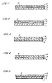
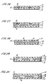
- Figures 1 and 4 illustrate two embodiments of a substrate according to the present invention.
- the substrate comprises a transparent polymer carrier layer (1) and a clear transparent, magnetic layer (2) formed from magnetic particles which are suspended in a varnish which is printed or coated onto the carrier layer (1).
- the size and distribution of the particles is controlled so that the thickness of the magnetic layer (2) is irrelevant.
- the size of the particles- may vary for different materials, examples of which are listed below. Although larger particles of these magnetic materials are lighter than smaller particles, the size must also be selected to enable painting or coating of the- varnish containing the particles.
- the invention requires the use of flake nickel magnetic materials, which have little or no magnetic remanence in the absence of an applied magnetic field, and preferably a coercivity of less than 7958 A/M (100 oersteds), and more preferably less that 3979 A/M (50 oersteds).
- Suitable materials must have a sufficiently high saturation magnetisation.
- Flake nickel materials can be used with surprising advantages. These materials have a small coercivity and a highly detectable remanence, and still give a transparent film. As is well known, the thinner and more flake like the particles, the greater the anisotropy and therefore the resulting covercivity and remanence. The remanence is high enough to be detectable on inductive machine read heads, which are the older more well known machines, without the need for the newer magnet-resistive heads.
- Suitable varnishes include 1462 from Luminescence, VHL 31534 from Sun Chemicals or 31833XSN, 20784XSN and 90838XSN, all from Coates Lorilleux.
- the carrier layer (1) may be PET, BOPP or another suitable polymer.
- the magnetic particles may be incorporated in the polymer layer (6) itself. From herein it should be appreciated that the use of a coated polymer layer (1) or a polymer layer (6) containing the magnetic particles are interchangeable within all the described embodiments.
- the substrate is provided with indicia formed from a plurality of opaque and non-opaque regions, which may be metallised, demetallised, printed or provided in another manner.
- the magnetic layer (2) may be located below the indicia, over the indicia, or in a full or partial layer which may or may not be in register with the indicia.
- the transparent magnetic layer (2,6) is preferably vacuum metallised and then selectively demetallised in a known manner to provide the indicia, which are formed by metallised regions (3) and demetallised regions (4).
- the resulting substrate can therefore have both public (overt) and machine readable (covert) features.
- a further polymer layer (5) (12 ⁇ m polyester for example) may optionally be laminated to the aforementioned substrate to cover the metallised and demetallised regions (3,4) to improve its durability.
- the additional polymer layer (5) may or may not contain magnetic particles depending upon requirements.
- the thus formed substrate may then be slit in register to form thin strips suitable for inclusion as security threads into banknotes or other security documents, such as credit, debit and other cards.
- Typical widths for security threads lie in the range 0.5mm to 50mm, and more preferably 1mm to 10mm.
- the use of the substrate of the present invention is not merely limited to use as security threads, but may also be used to provide other security media such as secure tear tapes for brand protection, or a secure substrate for the manufacture of holograms, labels, transfers, hang tags, certificates, bonds, cheques, banknotes and other documents of value.
- the substrate is particularly suitable for manufacturing plastic banknotes. When utilised as a substrate for such applications it is envisaged that an opaque ink receptive coating be applied over at least part of the substrate.
- the secure substrate described above can be further enhanced as will be understood by those skilled in the art.
- Such enhancements include, but are not limited to, the application of luminescent, thermochromic and, photochromic materials and embossed optically variable devices. Examples of how this might be achieved are described in EP-A-319157 , GB-A-2274428 , WO-A-00/54985 , and WO-A-00/39391 .
- a clear magnetic layer (2,6) means that the effects of such additional features are not obscured or interfered with by any colouring in the magnetic layer (2,6). With reference to the use of visible pigmentation or dyes, this allows the full spectrum of colours to be exhibited. Known systems using hard magnetics are tinted, often orange or brown, which prevents the use of yellow or other lightly coloured effects. This is particularly pronounced when using luminescent materials.
- Such a thread may use interspersed magnetic and text regions, or it could incorporate a coded format, such as that described in EP-A-407550 or a fixed length or code or use special thickness or coercivity variants to achieve a code.
- Fixed length coding is a spatially variant of magnetic print with a repeat length equal for, say, all denominations of a particular currency or security document set. The advantage to this type of coding is that the clocking of the code during read is easily established without the need for clocking bits in the code formant.
- a magnetic layer could be coated onto at least a part of the substrate to provide a magnetic code. Said additional magnetic layer could contain a magnetic material of different coercivity to that of the substrate film.
- the polymer carrier (1) is provided by a 12 ⁇ m standard polyester film which is coated at a coat weight of 0.002 kg/m 2 (2gsm) with a varnish (2) containing 0.1-50%, more preferably 1-30%, by weight of magnetic material.
- a metallic reflection-enhancing layer such as aluminium, is applied, although other metals such as copper could be used.
- This metallic layer is printed with a resist layer defining indicia and is then exposed to a caustic etch solution which removes the metal not protected by the resist.
- the caustic solution is washed away to reveal metallised regions (3) and demetallised regions (4), defining indicia.
- An additional layer (5) of 12 ⁇ m polyester may then be applied using a layer of adhesive to improve durability of the substrate.
- the thus formed substrate may then be slit in register to form security threads for inclusion into paper or polymer as described in EP-A-59056 and GB-A-0111452.9 respectively.
- a further layer of adhesive is preferably applied to one or both sides of the substrate to ensure secure location of the thread within a sheet of paper.
- further barrier layers are preferably provided on either side of the metallic layer to prevent environmental attack.
- FIGS. 2 and 3 Potential alternative constructions are shown in figures 2 and 3 .
- a metallised polymer film e.g. 12 ⁇ m metallised Type S from DuPont is demetallised as described above prior to application of the magnetic varnish layer.
- Figure 2 shows the varnish layer applied onto the demetallised surface and figure 3 shows the varnish layer applied on the opposite side to the demetallised layer.
- a layer of a pressure sensitive or hot melt adhesive (7) is subsequently applied to either of the polymer layers (1,5) of the substrate of Example 1, and strips of the substrate may be used as a tear tape for secure packaging.
- FIGs 6 and 7 show alternative constructions with the varnish layer applied onto the demetallised layer on the opposite side of the demetallised layer.
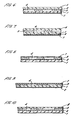
- a layer of pressure sensitive or hot melt adhesive (7) may be applied to the partially metallised surface (3,4) as shown in Fig. 8 .
- This provides the additional benefit that tapes made from the substrate now show some tamper evident properties. When such a tape is removed from the packaging or substrate the metal region (3) will be irreversibly removed to clearly illustrate tampering.
- a suitable pressure sensitive adhesive would be Indatex SE 5219 (applied at between 1gsm-20gsm, and more preferably at 8gsm).
- Figure 9 shows an alternative construction with the varnish layer applied to the opposite side of the demetallised layer.
- the magnetic particles have been included as part of the polymer carrier layer (6), as shown in Fig. 4 .
- 0.1-50% by weight of magnetic material would be included in the polyester, which is preferably a 12 ⁇ m film, or more preferably 1-30% by weight of magnetic material.
- the lower range of loading can be used where more sophisticated detection equipment is available.
- the polymer can then be further processed as described above.
- a high refractive index (HRI) layer (8) such as ZnS or a polymer liquid crystal layer can be applied in preference to or in addition to the partial metal layer (3,4) as shown in figure 5 to provide an iridescent effect in the metallic regions (3).
- HRI refractive index
- a dark or black background layer will need to be located behind any liquid crystal layer to cause the colourshift effect.
- FIGs 11 and 12 show alternative constructions where the varnish layer is applied onto the partial metal layer or onto the opposite side to the partial metal layer.
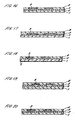
- opaque inks may be printed in selected regions (9) onto the transparent magnetic media containing layer (2,6) to form the indicia, as shown in Figures 13 to 15 , using any of the traditional print processes such as gravure, flexo, intaglio, litho, thermal transfer, dye diffusion and so forth. Additional security can be achieved using iridescent, luminescent (visible or invisible in daylight), optically variable, liquid crystal, thermochromic or photochromic inks in conjunction with, or as an alternative to, the opaque ink. It is preferable that such inks be applied in selected regions of the substrate so as to overlie or highlight the indicia, or even provide additional indicia.
- an HRI or polymer liquid crystal layer (8) may be provided.
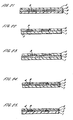
- the inks described above may also be applied in selected regions (9) in addition to demetallised indicia to further enhance security as shown in Figs. 16 to 19 with the HRI or polymer liquid crystal layer (8) applied thereover, or with a second polymer layer (5) as shown in Figs. 20 to 23 .
- the printed regions (9) are located within the demetallised regions 4, but not wholly filling them.
- an optically variable device such as a hologram, Kinegram or Exelgram.
- an additional embossing lacquer (10) is applied on to the substrate and embossed to provide an embossed surface (11).
- the reflection enhancing layer may be metal, as shown in Figs. 28 to 31 , or an HRI layer, as shown in Figs. 32 to 34 .
- Figures 28 to 31 show alternative constructions for the optically variable device utilising a metallic reflection enhancing layer.
- Figures 32 to 34 show alternative constructions for utilising the HRI reflection enhancing layer.
- Figure 35 illustrates an alternative construction whereby the coated film (1,2) is metallised and, selectively demetallised.
- An embossing lacquer (10) is applied, which is then embossed.
- An optional protective polymer layer(s) is applied to the embossed surface (11).
- Figure 2 illustrates a further alternative construction, which is a variant of that shown in Figure 1 , whereby the polymer carrier layer (1) has a metal layer applied thereto which is partially demetallised to form a partially metallised surface (3,4).
- the varnish (2) containing the magnetic material is then applied to the partially metallised surface (3,4).
- An additional protective layer (5) may then applied over the layer of varnish (2).
- the varnish (2) may first be applied to the protective layer (5) and this construction laminated to the partially demetallised structure (3,4).
- the substrate has two partially metallised layers (3,4). This is achieved by partially demetallising the first carrier layer (1) and, in a separate process, partially demetallising a second additional carrier layer (5).
- the magnetic material containing varnish (2) is applied to the partially metallised surface (3,4) of the first layer (1) and a laminating adhesive (12) applied to enable the second layer (5) with its demetallised surface (3,4) to be adhered to the first layer (1).
- an additional magnetic layer (10) is applied to the transparent magnetic media containing layer (2).
- the additional magnetic layer (10) is preferably discontinuous and also transparent, but incorporates a material of differing coercivity to that of layer (2).
- a non-transparent magnetic material may be used in layer 10.
- the additional layer (10) may also comprise several different magnetic materials printed sequentially to define a code, either abutting or overlapping to form a continuous layer.
- FIG. 38 This is a further example of a coded substrate, as illustrated in Figure 38 , in which the magnetic material containing varnish (2) is applied in a discontinuous manner to define a code.
- the code may be printed with several materials having different coercivities. In this example the need for an additional magnetic layer as described in Example 13 is removed. However, as with the previous examples, where using materials of differing coercivities, these can be printed in sequence either abutting or overlapping to form a continuous layer. In this Example numeral (13) denotes an uncoated magnetic region. In an alternative embodiment, the code does not need to be in register with the indicia.
- the demetallised construction consisting of the carrier layer (1) and partially metallised surface (3,4) can be formed separately from the transparent magnetic construction comprising the protective layer (5) with the magnetic material containing varnish (2) and then laminated together using a suitable adhesive.
Abstract
Description
- The invention relates to improvements in substrates and in particular to new substrates having magnetic and visual security features, which provide security against imitation.
- It is widely known to use in banknotes and other security documents security elements, such as security threads or strips. These threads are partially or wholly embedded in a paper or plastic substrate, and generally provide different viewing conditions depending on whether the security document is viewed in transmitted or reflected light.
-
EP-A-319157 - For a number of years banknote issuing authorities have had an interest in combining both the public recognition properties of Cleartext® with the covert properties of a machine readable feature. To this end it is preferable to utilise machine readable features that can be read using detectors already available to the banknote issuing authorities. Examples of such machine readable devices are described in
WO-A-92/11142 EP-A-773872 - The security device of
WO-A-92/11142 WO-A-92/11142 - A more satisfactory solution, from the processibility, ease of character recognition and aesthetics points of view, would be to manufacture a device of the kind described in
EP-A-0319157 from a metal which is itself magnetic such that the size of the characters and ratio of character height:thread width of the Cleartext® product is maintained, whilst providing direct compatibility with existing magnetic thread detectors. One means of achieving this is disclosed in Research Disclosure No. 323 of March 1991. In this Research Disclosure, a magnetic material is deposited onto a flexible substrate by vacuum sputtering or other known techniques; the non-metallised regions are created by selective printing of a resist layer and subsequent chemical etching. The disclosed magnetic materials may be nickel, cobalt, iron or alloys thereof with a preferred combination of cobalt:nickel in the ratio 85:15%. The disadvantage of this method is that vacuum deposition of cobalt:nickel to the necessary thickness is a relatively slow process and somewhat wasteful of cobalt, an expensive material. Furthermore, subsequent to this vacuum deposition process, further significant processing is required to etch the characters. The resultant product is therefore relatively expensive. - A further alternative approach is described in
EP-A-773872 - One further approach is detailed in
WO-A-9928852 -
FR 2 771 111 A -
US 5 697 649 A discloses a security substrate comprising a transparent polymer carrier layer and a continuous magnetic layer (without flakes) with nickel magnetic material and having a coercivity of less than 5000 A/m (63 oersteds). The magnetic layer is not disclosed as being transparent. - The present invention therefore seeks to provide a security substrate that may be slit into security threads for partially or wholly embedding into paper or polymer which has acceptable magnetic and visual characteristics as described above and also greatly simplifies the manufacturing process. Such a simplification produces costs savings for both manufacture and materials as levels of spoil are greatly reduced.
- The invention therefore provides a security substrate comprising a transparent polymer carrier layer bearing indicia formed from a plurality of opaque and non-opaque regions and a clear transparent magnetic layer supported by the carrier layer containing a distribution of particles of a magnetic flake nickel material of a size and distributed in a concentration at which the magnetic layer remains clear and transparent.
- The advantage of using a clear magnetic layer means that this type of magnetic feature can be incorporated into existing designs of security elements (threads) without affecting their visual appearance. This avoids the need to retrain the public and other handlers in recognition of the security features of security documents incorporating such elements. It thus allows for a seamless introduction of a magnetic feature, without the need to withdraw existing security documents. Both variations, with and without the magnetic feature, can be used side by side without confusion occurring.
- Additionally, counterfeiters are not likely to be aware of the existence of the transparent magnetic features and therefore are less likely to try to include one in any counterfeits, thus making it easier to detect counterfeits.
- A preferred embodiment of the present invention will now be described by way of example only, with reference to the accompanying drawings in which:-
-
Figures 1, 2, and 3 are cross-sectional side elevations of a substrate according to the present invention; -
Figure 4 is cross-sectional side elevation of an alternative substrate to that shown inFigure 1 ; -
Figures 5 ,6, and 7 are cross-sectional side elevations of further alternative embodiments of the substrate ofFigure 1 with an adhesive layer applied, for use in tear tapes; -
Figures 8 and 9 are cross-sectional side elevations of other alternative substrates to that shown inFigure 1 with an adhesive applied to the demetallised surface, for use as a tamper evident tear tape; -
Figures 10 ,11, and 12 are cross-sectional side elevations of further alternative substrates to that shown inFigure 1 incorporating a high reflective index or polymer liquid crystal layer; -
Figures 13, 14, and 15 are cross-sectional side elevations of further alternative substrates to that ofFigure 1 , with an HRI or polymer liquid crystal layer, no metallisation and including a print feature; -
Figures 16, 17, 18 and 19 are cross-sectional side elevations of further alternative substrates to those shown inFigures 13, 14 and 15 , but with the addition of a demetallised layer; -
Figures 20 ,21, 22 and 23 are cross-sectional side elevations of an alternative substrate to that shown inFigures 16, 17, 18 and 19 with the high refractive index or polymer liquid crystal layer replaced by a second clear polymer layer; -
Figures 24, 25 ,26 and 27 are cross-sectional side elevations of an alternative substrate to that shown inFigure 20 but with the print features located within the demetallised region; -
Figures 28 to 35 are cross-sectional side elevations of further alternative substrates incorporating optically variable device; -
Figure 36 is a cross-sectional side elevation of an alternative substrate to that ofFigure 2 , but with two demetallised layers, one on either side of the transparent magnetic media containing layer; and -
Figures 37 and 38 are cross-sectional side elevations of further alternative substrates which are coded. - The present invention makes use of transparent magnetic materials that are now available from a number of suppliers. In the most basic form such transparent magnetic media comprises a polymeric film in which have been suspended magnetic particles of flake nickel magnetic material. The particles themselves are not colourless, but the degree of concentration is such as to allow the polymeric film to remain clear and transparent. Various other forms of transparent magnetic media are described in the prior art any of which would be suitable for the present application. In particular, the wider the thread, the lower the concentration of magnetic particles is required for accurate machine detection, due to the fact that the signal recovery is considerably differentiated from the formal cash processing system noise.
-
Figures 1 and 4 illustrate two embodiments of a substrate according to the present invention. InFigure 1 the substrate comprises a transparent polymer carrier layer (1) and a clear transparent, magnetic layer (2) formed from magnetic particles which are suspended in a varnish which is printed or coated onto the carrier layer (1). The size and distribution of the particles is controlled so that the thickness of the magnetic layer (2) is irrelevant. The size of the particles-may vary for different materials, examples of which are listed below. Although larger particles of these magnetic materials are lighter than smaller particles, the size must also be selected to enable painting or coating of the- varnish containing the particles. - The invention requires the use of flake nickel magnetic materials, which have little or no magnetic remanence in the absence of an applied magnetic field, and preferably a coercivity of less than 7958 A/M (100 oersteds), and more preferably less that 3979 A/M (50 oersteds).
- Suitable materials must have a sufficiently high saturation magnetisation. Flake nickel materials can be used with surprising advantages.. These materials have a small coercivity and a highly detectable remanence, and still give a transparent film. As is well known, the thinner and more flake like the particles, the greater the anisotropy and therefore the resulting covercivity and remanence. The remanence is high enough to be detectable on inductive machine read heads, which are the older more well known machines, without the need for the newer magnet-resistive heads.
- Suitable varnishes include 1462 from Luminescence, VHL 31534 from Sun Chemicals or 31833XSN, 20784XSN and 90838XSN, all from Coates Lorilleux. The carrier layer (1) may be PET, BOPP or another suitable polymer.
- Alternatively, as shown in
Fig. 4 , the magnetic particles may be incorporated in the polymer layer (6) itself. From herein it should be appreciated that the use of a coated polymer layer (1) or a polymer layer (6) containing the magnetic particles are interchangeable within all the described embodiments. - The substrate is provided with indicia formed from a plurality of opaque and non-opaque regions, which may be metallised, demetallised, printed or provided in another manner. The magnetic layer (2) may be located below the indicia, over the indicia, or in a full or partial layer which may or may not be in register with the indicia.
- The transparent magnetic layer (2,6) is preferably vacuum metallised and then selectively demetallised in a known manner to provide the indicia, which are formed by metallised regions (3) and demetallised regions (4).
- It should be noted that any magnetic print feature/code used in conjunction with demetallisation does not need to be registered therewith.
- The resulting substrate can therefore have both public (overt) and machine readable (covert) features.
- A further polymer layer (5) (12µm polyester for example) may optionally be laminated to the aforementioned substrate to cover the metallised and demetallised regions (3,4) to improve its durability. The additional polymer layer (5) may or may not contain magnetic particles depending upon requirements.
- The thus formed substrate may then be slit in register to form thin strips suitable for inclusion as security threads into banknotes or other security documents, such as credit, debit and other cards. Typical widths for security threads lie in the range 0.5mm to 50mm, and more preferably 1mm to 10mm. The use of the substrate of the present invention is not merely limited to use as security threads, but may also be used to provide other security media such as secure tear tapes for brand protection, or a secure substrate for the manufacture of holograms, labels, transfers, hang tags, certificates, bonds, cheques, banknotes and other documents of value. In particular the substrate is particularly suitable for manufacturing plastic banknotes. When utilised as a substrate for such applications it is envisaged that an opaque ink receptive coating be applied over at least part of the substrate.
- The secure substrate described above can be further enhanced as will be understood by those skilled in the art. Such enhancements include, but are not limited to, the application of luminescent, thermochromic and, photochromic materials and embossed optically variable devices. Examples of how this might be achieved are described in
EP-A-319157 GB-A-2274428 WO-A-00/54985 WO-A-00/39391 - The use of a clear magnetic layer (2,6) means that the effects of such additional features are not obscured or interfered with by any colouring in the magnetic layer (2,6). With reference to the use of visible pigmentation or dyes, this allows the full spectrum of colours to be exhibited. Known systems using hard magnetics are tinted, often orange or brown, which prevents the use of yellow or other lightly coloured effects. This is particularly pronounced when using luminescent materials.
- It would also be possible to use the invention to provide a coded security thread. Such a thread may use interspersed magnetic and text regions, or it could incorporate a coded format, such as that described in
EP-A-407550 - The invention will now be described in more detail by reference to the following examples.
- In a first example, as shown in
Fig. 1 , the polymer carrier (1) is provided by a 12 µm standard polyester film which is coated at a coat weight of 0.002 kg/m2 (2gsm) with a varnish (2) containing 0.1-50%, more preferably 1-30%, by weight of magnetic material. The lower range of loading can be used where more sophisticated detection equipment is available. Onto this carrier (1) a metallic reflection-enhancing layer, such as aluminium, is applied, although other metals such as copper could be used. This metallic layer is printed with a resist layer defining indicia and is then exposed to a caustic etch solution which removes the metal not protected by the resist. The caustic solution is washed away to reveal metallised regions (3) and demetallised regions (4), defining indicia. Alternatively any of the known methods for demetallisation could be used. An additional layer (5) of 12µm polyester may then be applied using a layer of adhesive to improve durability of the substrate. The thus formed substrate may then be slit in register to form security threads for inclusion into paper or polymer as described inEP-A-59056 GB-A-0111452.9 - Potential alternative constructions are shown in
figures 2 and 3 . In both these examples a metallised polymer film e.g. 12 µm metallised Type S from DuPont is demetallised as described above prior to application of the magnetic varnish layer.Figure 2 shows the varnish layer applied onto the demetallised surface andfigure 3 shows the varnish layer applied on the opposite side to the demetallised layer. - In a second example, as shown in
Fig. 5 , a layer of a pressure sensitive or hot melt adhesive (7) is subsequently applied to either of the polymer layers (1,5) of the substrate of Example 1, and strips of the substrate may be used as a tear tape for secure packaging. -
Figures 6 and 7 show alternative constructions with the varnish layer applied onto the demetallised layer on the opposite side of the demetallised layer. - As a further alternative a layer of pressure sensitive or hot melt adhesive (7) may be applied to the partially metallised surface (3,4) as shown in
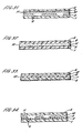
Fig. 8 . This provides the additional benefit that tapes made from the substrate now show some tamper evident properties. When such a tape is removed from the packaging or substrate the metal region (3) will be irreversibly removed to clearly illustrate tampering. A suitable pressure sensitive adhesive would be Indatex SE 5219 (applied at between 1gsm-20gsm, and more preferably at 8gsm). -
Figure 9 shows an alternative construction with the varnish layer applied to the opposite side of the demetallised layer. - In this example the magnetic particles have been included as part of the polymer carrier layer (6), as shown in
Fig. 4 . In a typical example, 0.1-50% by weight of magnetic material would be included in the polyester, which is preferably a 12µm film, or more preferably 1-30% by weight of magnetic material. The lower range of loading can be used where more sophisticated detection equipment is available. The polymer can then be further processed as described above. - As an alternative a high refractive index (HRI) layer (8) such as ZnS or a polymer liquid crystal layer can be applied in preference to or in addition to the partial metal layer (3,4) as shown in
figure 5 to provide an iridescent effect in the metallic regions (3). However, a dark or black background layer will need to be located behind any liquid crystal layer to cause the colourshift effect. -
Figures 11 and 12 show alternative constructions where the varnish layer is applied onto the partial metal layer or onto the opposite side to the partial metal layer. - If no metal layer is present, opaque inks may be printed in selected regions (9) onto the transparent magnetic media containing layer (2,6) to form the indicia, as shown in
Figures 13 to 15 , using any of the traditional print processes such as gravure, flexo, intaglio, litho, thermal transfer, dye diffusion and so forth. Additional security can be achieved using iridescent, luminescent (visible or invisible in daylight), optically variable, liquid crystal, thermochromic or photochromic inks in conjunction with, or as an alternative to, the opaque ink. It is preferable that such inks be applied in selected regions of the substrate so as to overlie or highlight the indicia, or even provide additional indicia. Optionally an HRI or polymer liquid crystal layer (8) may be provided. - The inks described above may also be applied in selected regions (9) in addition to demetallised indicia to further enhance security as shown in
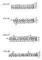
Figs. 16 to 19 with the HRI or polymer liquid crystal layer (8) applied thereover, or with a second polymer layer (5) as shown inFigs. 20 to 23 . - In this example, as shown in
Figs. 24 to 27 the printed regions (9) are located within the demetallised regions 4, but not wholly filling them. - It is also possible to produce a variant of the invention incorporating an optically variable device such as a hologram, Kinegram or Exelgram. Here an additional embossing lacquer (10) is applied on to the substrate and embossed to provide an embossed surface (11). The reflection enhancing layer may be metal, as shown in
Figs. 28 to 31 , or an HRI layer, as shown inFigs. 32 to 34 . -
Figures 28 to 31 show alternative constructions for the optically variable device utilising a metallic reflection enhancing layer.Figures 32 to 34 show alternative constructions for utilising the HRI reflection enhancing layer. -
Figure 35 illustrates an alternative construction whereby the coated film (1,2) is metallised and, selectively demetallised. An embossing lacquer (10) is applied, which is then embossed. An optional protective polymer layer(s) is applied to the embossed surface (11). -
Figure 2 illustrates a further alternative construction, which is a variant of that shown inFigure 1 , whereby the polymer carrier layer (1) has a metal layer applied thereto which is partially demetallised to form a partially metallised surface (3,4). The varnish (2) containing the magnetic material is then applied to the partially metallised surface (3,4). An additional protective layer (5) may then applied over the layer of varnish (2). Alternatively, the varnish (2) may first be applied to the protective layer (5) and this construction laminated to the partially demetallised structure (3,4). - In this example, as illustrated in
Figure 36 , the substrate has two partially metallised layers (3,4). This is achieved by partially demetallising the first carrier layer (1) and, in a separate process, partially demetallising a second additional carrier layer (5). The magnetic material containing varnish (2) is applied to the partially metallised surface (3,4) of the first layer (1) and a laminating adhesive (12) applied to enable the second layer (5) with its demetallised surface (3,4) to be adhered to the first layer (1). - This is an example of a coded thread as mentioned previously and as illustrated in
Figure 37 . In this example an additional magnetic layer (10) is applied to the transparent magnetic media containing layer (2). The additional magnetic layer (10) is preferably discontinuous and also transparent, but incorporates a material of differing coercivity to that of layer (2). Although it is preferred that the layer (10) is transparent, a non-transparent magnetic material may be used inlayer 10. The additional layer (10) may also comprise several different magnetic materials printed sequentially to define a code, either abutting or overlapping to form a continuous layer. - This is a further example of a coded substrate, as illustrated in
Figure 38 , in which the magnetic material containing varnish (2) is applied in a discontinuous manner to define a code. The code may be printed with several materials having different coercivities. In this example the need for an additional magnetic layer as described in Example 13 is removed. However, as with the previous examples, where using materials of differing coercivities, these can be printed in sequence either abutting or overlapping to form a continuous layer. In this Example numeral (13) denotes an uncoated magnetic region. In an alternative embodiment, the code does not need to be in register with the indicia. - In all the aforementioned examples it should be noted that, as mentioned in conjunction with Example 34, the demetallised construction consisting of the carrier layer (1) and partially metallised surface (3,4) can be formed separately from the transparent magnetic construction comprising the protective layer (5) with the magnetic material containing varnish (2) and then laminated together using a suitable adhesive.
Claims (21)
- A security substrate comprising a transparent polymer carrier layer bearing indicia formed from a plurality of opaque and non-opaque regions and a clear transparent magnetic layer supported by the carrier layer containing a distribution of particles of a flake nickel magnetic material, having a low coercivity of less than 7958 A/M (100 oersteds) and a highly detectable remanence, of a size and distributed in a concentration at which the magnetic layer remains clear and transparent.
- A security substrate-as claimed in claim 1 in which the transparent magnetic layer.comprises a varnish in which are suspended the magnetic-particles.
- A security substrate as claimed in claims 1 or 2 in which the transparent magnetic layer lies between the carrier layer and the indicia.
- A security substrate as claimed in claims 1 or 2 in which the indicia are formed on the carrier layer and the transparent magnetic layer covers the indicia.
- A security substrate as claimed in any one of the preceding claims further comprising an additional layer of a transparent polymer laminated to the magnetic layer and/or indicia.
- A security substrate as claimed in any one of the preceding claims further comprising a layer of adhesive applied to at least one side of the substrate.
- A security substrate as claimed in any one of the preceding claims in which a layer of adhesive overlies the indicia.
- A security substrate as claimed in any one of the preceding claims further comprising a layer of high refractive index material.
- A security substrate as claimed in any one of the preceding claims in which the indicia are provided by partially demetallising a metal layer, with remaining metal forming the opaque regions and the demetallised regions forming the non-opaque regions.
- A security substrate as claimed in any one of the preceding claims in which the indicia are printed.
- A security substrate as claimed in any one of the preceding claims further including additional printed regions formed from one or more inks having iridescent, luminescent, optically variable, liquid crystal, thermochromic and/or photochromic properties.
- A security substrate as claimed in any one of the preceding claims comprising indicia provided by demetallised and metallised regions and printed indicia.
- A security substrate as claimed in claim 12 in which the printed indicia overlie at least some of the metallic regions.
- A security substrate as claimed in claim 12 in which the printed indicia lie within the demetallised regions.
- A security substrate as claimed in any one of the preceding claims further comprising an optically variable device.
- A security substrate as claimed in claim 15 in which the optically variable device is formed by embossing a layer of embossing lacquer.
- A security substrate as claimed in claim 15 in which the embossing lacquer lies between the magnetic layer and the indicia.
- A security substrate as claimed in claim 16 in which the embossing layer lies between the transparent magnetic layer and a layer of high refractive index.
- A security substrate as claimed in claim 16 wherein the embossing layer overlies the indicia.
- An- elongate security element made by the step of slitting the substrate as claimed in any one of the preceding claims in register with the indicia.
- A security document comprising a paper or polymer substrate incorporating a security element as claimed in claim 20.
Priority Applications (1)
| Application Number | Priority Date | Filing Date | Title |
|---|---|---|---|
| SI200332093T SI1497141T1 (en) | 2002-04-25 | 2003-04-24 | Transparent security substrate with magnetic particles |
Applications Claiming Priority (3)
| Application Number | Priority Date | Filing Date | Title |
|---|---|---|---|
| GB0209564 | 2002-04-25 | ||
| GBGB0209564.4A GB0209564D0 (en) | 2002-04-25 | 2002-04-25 | Improvements in substrates |
| PCT/GB2003/001678 WO2003091952A2 (en) | 2002-04-25 | 2003-04-24 | Transparent security substrate with magnetic paricles |
Publications (2)
| Publication Number | Publication Date |
|---|---|
| EP1497141A2 EP1497141A2 (en) | 2005-01-19 |
| EP1497141B1 true EP1497141B1 (en) | 2011-09-28 |
Family
ID=9935561
Family Applications (2)
| Application Number | Title | Priority Date | Filing Date |
|---|---|---|---|
| EP03722772A Withdrawn EP1497142A2 (en) | 2002-04-25 | 2003-04-24 | Transparent security substrate with magnetic particles |
| EP03722756A Revoked EP1497141B1 (en) | 2002-04-25 | 2003-04-24 | Transparent security substrate with magnetic particles |
Family Applications Before (1)
| Application Number | Title | Priority Date | Filing Date |
|---|---|---|---|
| EP03722772A Withdrawn EP1497142A2 (en) | 2002-04-25 | 2003-04-24 | Transparent security substrate with magnetic particles |
Country Status (8)
| Country | Link |
|---|---|
| US (4) | US20050238851A1 (en) |
| EP (2) | EP1497142A2 (en) |
| AT (1) | ATE526173T1 (en) |
| AU (2) | AU2003229919A1 (en) |
| ES (1) | ES2369886T3 (en) |
| GB (3) | GB0209564D0 (en) |
| SI (1) | SI1497141T1 (en) |
| WO (2) | WO2003091952A2 (en) |
Cited By (4)
| Publication number | Priority date | Publication date | Assignee | Title |
|---|---|---|---|---|
| EP2965920A1 (en) | 2014-07-09 | 2016-01-13 | Sicpa Holding Sa | Optically variable magnetic security threads and stripes |
| DE102014011663A1 (en) | 2014-08-04 | 2016-02-04 | Giesecke & Devrient Gmbh | Security element and value document |
| EP3034315A1 (en) | 2014-12-17 | 2016-06-22 | Giesecke & Devrient GmbH | Security element, method for its production and data carrier equipped wth the security element |
| WO2022073642A1 (en) * | 2020-10-09 | 2022-04-14 | Giesecke+Devrient Currency Technology Gmbh | Security element having a translucent partial region |
Families Citing this family (61)
| Publication number | Priority date | Publication date | Assignee | Title |
|---|---|---|---|---|
| US7551750B2 (en) * | 2002-01-09 | 2009-06-23 | Jds Uniphase Corporation | Holographic digital watermark |
| ITMI20021575A1 (en) † | 2002-07-17 | 2004-01-19 | Elmiva S A S Di Walter Mantega | SECURITY ELEMENT FOR BANKNOTE DOCUMENTS SECURITY CARDS AND SIMILAR |
| US7339999B2 (en) * | 2004-01-21 | 2008-03-04 | Qualcomm Incorporated | Pilot transmission and channel estimation for an OFDM system with excess delay spread |
| US7865734B2 (en) | 2005-05-12 | 2011-01-04 | The Invention Science Fund I, Llc | Write accessibility for electronic paper |
| US8281142B2 (en) | 2005-01-20 | 2012-10-02 | The Invention Science Fund I, Llc | Notarizable electronic paper |
| US8640259B2 (en) * | 2005-01-20 | 2014-01-28 | The Invention Science Fund I, Llc | Notarizable electronic paper |
| US8063878B2 (en) | 2005-01-20 | 2011-11-22 | The Invention Science Fund I, Llc | Permanent electronic paper |
| US7739510B2 (en) | 2005-05-12 | 2010-06-15 | The Invention Science Fund I, Inc | Alert options for electronic-paper verification |
| ES2264372B1 (en) * | 2005-03-10 | 2007-12-01 | Fabrica Nacional De Moneda Y Timbre - Real Casa De La Moneda | SAFETY STRIP, SECURITY PAPER THAT INCLUDES SUCH STRIP AND SECURITY DOCUMENT AND TICKET THAT INCORPORATE SUCH PAPER. |
| EP1714795A1 (en) * | 2005-04-20 | 2006-10-25 | Hueck Folien Ges.m.b.H | Security element with a spacially separated magnetic code, method and apparatus for its production and its applcation |
| AT502160B1 (en) * | 2005-07-12 | 2013-07-15 | Hueck Folien Gmbh | SAFETY FOIL FOR SECURING DOCUMENTS |
| US7895527B2 (en) | 2005-07-15 | 2011-02-22 | Siemens Medical Solutions Usa, Inc. | Systems, user interfaces, and methods for processing medical data |
| GB2430647B (en) * | 2005-09-29 | 2008-09-17 | Rue De Int Ltd | Security device for security substrates |
| AU2006317160A1 (en) * | 2005-11-22 | 2007-05-31 | Merck Patent Gmbh | Process for a thermal transfer of a liquid crystal film using a transfer element |
| US20080024917A1 (en) * | 2006-02-24 | 2008-01-31 | John Hynes | Holographic magnetic stripe demetalization security |
| GB2438383B (en) | 2006-05-26 | 2008-10-08 | Rue De Int Ltd | Improvements in substrates |
| GB0615919D0 (en) | 2006-08-10 | 2006-09-20 | Rue De Int Ltd | Photonic crystal security device |
| GB0615921D0 (en) | 2006-08-10 | 2006-09-20 | Rue De Int Ltd | Photonic crystal security device |
| FR2907136B1 (en) | 2006-10-12 | 2010-01-15 | Arjowiggins | SECURITY TAPE, SHEET AND SECURITY DOCUMENT COMPRISING IT AND METHOD OF INCORPORATING IT |
| JP4959304B2 (en) * | 2006-11-22 | 2012-06-20 | 日本発條株式会社 | Identification medium, identification method, and identification apparatus |
| DE102007025667A1 (en) * | 2007-06-01 | 2008-12-04 | Giesecke & Devrient Gmbh | Endless material for security elements |
| AU2008258232B2 (en) | 2007-06-05 | 2013-12-05 | Bank Of Canada | Ink or toner compositions, methods of use, and products derived therefrom |
| GB2452078B (en) | 2007-08-23 | 2009-12-23 | Rue De Int Ltd | Security devices for security substrates |
| GB0720550D0 (en) | 2007-10-19 | 2007-11-28 | Rue De Int Ltd | Photonic crystal security device multiple optical effects |
| GB2456500B (en) | 2007-10-23 | 2011-12-28 | Rue De Int Ltd | Improvements in security elements |
| FR2922905B1 (en) * | 2007-10-26 | 2009-12-18 | Arjowiggins Licensing Sas | SAFETY STRUCTURE COMPRISING A THERMOCHROMIC ELEMENT AND A PHOTOCHROMIC ELEMENT |
| GB2457911B (en) | 2008-02-27 | 2010-05-12 | Rue De Int Ltd | Improved method for producing an optically varible security device |
| CA2727476A1 (en) * | 2008-06-12 | 2009-12-17 | Crane & Co., Inc. | Method for increasing adhesion between a security element and a fibrous sheet material |
| WO2010113192A1 (en) * | 2009-04-01 | 2010-10-07 | Fabriano Securities S.R.L. | Security element comprising magnetic areas of different coercivities, a method for its production and a method for reading information encoded in the element |
| DE102009020208A1 (en) | 2009-05-07 | 2010-11-11 | Merck Patent Gmbh | Method for coding products |
| GB0911792D0 (en) | 2009-07-07 | 2009-08-19 | Rue De Int Ltd | Photonic crystal material |
| GB2472247A (en) * | 2009-07-31 | 2011-02-02 | Innovia Films Sarl | Security document |
| GB0919108D0 (en) | 2009-10-30 | 2009-12-16 | Rue De Int Ltd | Security device |
| GB0919109D0 (en) | 2009-10-30 | 2009-12-16 | Rue De Int Ltd | Security device |
| GB0919112D0 (en) | 2009-10-30 | 2009-12-16 | Rue De Int Ltd | Security device |
| GB2474903B (en) | 2009-10-30 | 2012-02-01 | Rue De Int Ltd | Improvements in security devices |
| GB2476228B (en) | 2009-11-19 | 2012-02-01 | Rue De Int Ltd | Improvements in security devices |
| GB201003397D0 (en) | 2010-03-01 | 2010-04-14 | Rue De Int Ltd | Moire magnification security device |
| GB201003398D0 (en) | 2010-03-01 | 2010-04-14 | Rue De Int Ltd | Optical device |
| GB2478537B (en) | 2010-03-08 | 2013-07-24 | Rue De Int Ltd | Improvements in security documents |
| GB201007695D0 (en) | 2010-05-07 | 2010-06-23 | Rue De Int Ltd | Security device |
| US9708773B2 (en) | 2011-02-23 | 2017-07-18 | Crane & Co., Inc. | Security sheet or document having one or more enhanced watermarks |
| GB201107657D0 (en) * | 2011-05-09 | 2011-06-22 | Rue De Int Ltd | Security device |
| GB2493369B (en) | 2011-08-02 | 2013-09-25 | Rue De Int Ltd | Improvements in security devices |
| GB201212046D0 (en) | 2012-07-06 | 2012-08-22 | Rue De Int Ltd | Security devices |
| GB201313362D0 (en) | 2013-07-26 | 2013-09-11 | Rue De Int Ltd | Security Devices and Methods of Manufacture |
| GB201313363D0 (en) | 2013-07-26 | 2013-09-11 | Rue De Int Ltd | Security devices and method of manufacture |
| KR101676522B1 (en) * | 2013-11-29 | 2016-11-15 | 제일모직주식회사 | Gas barrier film and method for preparing the same |
| GB201400910D0 (en) | 2014-01-20 | 2014-03-05 | Rue De Int Ltd | Security elements and methods of their manufacture |
| GB2523994B (en) | 2014-03-06 | 2017-08-30 | De La Rue Int Ltd | Method of forming a security document |
| GB2549215B (en) | 2015-06-10 | 2018-07-25 | De La Rue Int Ltd | Security devices and methods of manufacture thereof |
| CN108349292B (en) * | 2015-11-12 | 2021-09-10 | 拉沃希尔有限公司 | Anti-counterfeiting device and method |
| GB201520085D0 (en) | 2015-11-13 | 2015-12-30 | Rue De Int Ltd | Methods of manufacturing image element arrays for security devices |
| GB2549724B (en) | 2016-04-26 | 2019-12-11 | De La Rue Int Ltd | Security devices and methods of manufacturing image patterns for security devices |
| US10679523B2 (en) | 2016-07-26 | 2020-06-09 | Savannah River Nuclear Solutions, Llc | Tamper indicating seal |
| DE102016014230A1 (en) | 2016-11-30 | 2018-05-30 | Giesecke & Devrient Gmbh | Value document, method of manufacturing the same and value document system |
| GB2576218B (en) | 2018-08-10 | 2021-09-15 | De La Rue Int Ltd | Security devices and methods of authentication thereof |
| GB2578117B (en) | 2018-10-16 | 2021-06-09 | De La Rue Int Ltd | Security devices and methods for their manufacture |
| WO2022053826A1 (en) | 2020-09-11 | 2022-03-17 | De La Rue International Limited | Security devices and methods of manufacture thereof |
| EP3939802A1 (en) * | 2020-09-29 | 2022-01-19 | Hueck Folien Gesellschaft m.b.H. | Substrate for producing security papers or security papers |
| GB202101267D0 (en) | 2021-01-29 | 2021-03-17 | De La Rue Int Ltd | Security devices and methods of manufacture thereof |
Citations (1)
| Publication number | Priority date | Publication date | Assignee | Title |
|---|---|---|---|---|
| US5697649A (en) * | 1995-05-11 | 1997-12-16 | Crane & Co., Inc. | Articles employing a magnetic security feature |
Family Cites Families (22)
| Publication number | Priority date | Publication date | Assignee | Title |
|---|---|---|---|---|
| US5766738A (en) * | 1979-12-28 | 1998-06-16 | Flex Products, Inc. | Paired optically variable article with paired optically variable structures and ink, paint and foil incorporating the same and method |
| IN173621B (en) | 1987-12-04 | 1994-06-18 | Portals Ltd | |
| EP0330733B1 (en) * | 1988-03-04 | 1994-01-26 | GAO Gesellschaft für Automation und Organisation mbH | Thread- or strip-like security element to be included in a security document, and a method of manufacturing same |
| GB2227451B (en) | 1989-01-20 | 1992-10-14 | Bank Of England The Governor A | Coding security threads for bank notes and security papers |
| GB8924111D0 (en) * | 1989-10-26 | 1989-12-13 | Amblehurst Ltd | Optical device |
| DE4041025C2 (en) * | 1990-12-20 | 2003-04-17 | Gao Ges Automation Org | Magnetic, metallic security thread with negative writing |
| GB9218216D0 (en) * | 1992-08-27 | 1992-10-14 | Payne P P Ltd | Improvements in or relating to tapes |
| DE4404128A1 (en) * | 1993-02-19 | 1994-08-25 | Gao Ges Automation Org | Security document and method for its manufacture |
| US5997849A (en) * | 1993-12-29 | 1999-12-07 | Chromatic Technologies, Inc. | Thermochromic ink formulations, nail lacquer and methods of use |
| DE4410431A1 (en) * | 1994-03-25 | 1995-09-28 | Giesecke & Devrient Gmbh | ID card protected against unauthorized reproduction with a copier |
| AU3120595A (en) | 1994-08-04 | 1996-03-04 | Portals Limited | A security product, a film and a method of manufacture of a security product |
| DE19611383A1 (en) * | 1996-03-22 | 1997-09-25 | Giesecke & Devrient Gmbh | Data carrier with optically variable element |
| US5988500A (en) * | 1996-05-17 | 1999-11-23 | Aveka, Inc. | Antiforgery security system |
| DE19650759A1 (en) * | 1996-12-06 | 1998-06-10 | Giesecke & Devrient Gmbh | Security element |
| DE19744953A1 (en) * | 1997-10-10 | 1999-04-15 | Giesecke & Devrient Gmbh | Security element with an auxiliary inorganic layer |
| FR2771111B1 (en) * | 1997-11-20 | 1999-12-17 | Arjo Wiggins Sa | SAFETY DOCUMENT COMPRISING MAGNETIC PARTICLES |
| US6930606B2 (en) * | 1997-12-02 | 2005-08-16 | Crane & Co., Inc. | Security device having multiple security detection features |
| UA52804C2 (en) | 1997-12-02 | 2003-01-15 | Текнікал Графікс Сек'Юріті Продактс, Ллс | Device for protecting documents by using magnetic and metallic protective elements (variants); method for producing the protection device (variants); method for identifying documents |
| CA2386792A1 (en) | 1999-10-07 | 2001-04-12 | Gerald J. Gartner | Security device with foil camouflaged magnetic regions and methods of making same |
| US6659507B2 (en) * | 2000-04-03 | 2003-12-09 | American Bank Note Holographics, Inc. | Enhanced security for tamper-apparent labels, seals or tags |
| US6808806B2 (en) * | 2001-05-07 | 2004-10-26 | Flex Products, Inc. | Methods for producing imaged coated articles by using magnetic pigments |
| WO2002101147A1 (en) * | 2001-06-08 | 2002-12-19 | Rexor | Security thread or transfer film for hot process marking of bank notes, documents or other articles to be made secure |
-
2002
- 2002-04-25 GB GBGB0209564.4A patent/GB0209564D0/en not_active Ceased
-
2003
- 2003-04-24 WO PCT/GB2003/001678 patent/WO2003091952A2/en not_active Application Discontinuation
- 2003-04-24 US US10/511,721 patent/US20050238851A1/en not_active Abandoned
- 2003-04-24 ES ES03722756T patent/ES2369886T3/en not_active Expired - Lifetime
- 2003-04-24 SI SI200332093T patent/SI1497141T1/en unknown
- 2003-04-24 AU AU2003229919A patent/AU2003229919A1/en not_active Abandoned
- 2003-04-24 GB GB0309335A patent/GB2387813B/en not_active Expired - Fee Related
- 2003-04-24 US US10/512,055 patent/US20050116464A1/en not_active Abandoned
- 2003-04-24 WO PCT/GB2003/001768 patent/WO2003091953A2/en not_active Application Discontinuation
- 2003-04-24 AT AT03722756T patent/ATE526173T1/en active
- 2003-04-24 EP EP03722772A patent/EP1497142A2/en not_active Withdrawn
- 2003-04-24 AU AU2003229935A patent/AU2003229935A1/en not_active Abandoned
- 2003-04-24 GB GB0309334A patent/GB2387812B/en not_active Expired - Lifetime
- 2003-04-24 EP EP03722756A patent/EP1497141B1/en not_active Revoked
-
2008
- 2008-08-18 US US12/222,839 patent/US9483719B2/en not_active Expired - Fee Related
- 2008-08-20 US US12/222,964 patent/US20090029123A1/en not_active Abandoned
Patent Citations (1)
| Publication number | Priority date | Publication date | Assignee | Title |
|---|---|---|---|---|
| US5697649A (en) * | 1995-05-11 | 1997-12-16 | Crane & Co., Inc. | Articles employing a magnetic security feature |
Cited By (6)
| Publication number | Priority date | Publication date | Assignee | Title |
|---|---|---|---|---|
| EP2965920A1 (en) | 2014-07-09 | 2016-01-13 | Sicpa Holding Sa | Optically variable magnetic security threads and stripes |
| US10166810B2 (en) | 2014-07-09 | 2019-01-01 | Sicpa Holding Sa | Optically variable magnetic security threads and stripes |
| DE102014011663A1 (en) | 2014-08-04 | 2016-02-04 | Giesecke & Devrient Gmbh | Security element and value document |
| EP3034315A1 (en) | 2014-12-17 | 2016-06-22 | Giesecke & Devrient GmbH | Security element, method for its production and data carrier equipped wth the security element |
| DE102014018890A1 (en) | 2014-12-17 | 2016-06-23 | Giesecke & Devrient Gmbh | Security element, method for producing the same and equipped with the security element disk |
| WO2022073642A1 (en) * | 2020-10-09 | 2022-04-14 | Giesecke+Devrient Currency Technology Gmbh | Security element having a translucent partial region |
Also Published As
| Publication number | Publication date |
|---|---|
| US20090029123A1 (en) | 2009-01-29 |
| GB2387812A (en) | 2003-10-29 |
| AU2003229935A1 (en) | 2003-11-10 |
| WO2003091953A2 (en) | 2003-11-06 |
| AU2003229919A1 (en) | 2003-11-10 |
| EP1497142A2 (en) | 2005-01-19 |
| ES2369886T3 (en) | 2011-12-07 |
| SI1497141T1 (en) | 2012-02-29 |
| WO2003091953A3 (en) | 2004-02-12 |
| GB2387813B (en) | 2004-07-14 |
| AU2003229919A8 (en) | 2003-11-10 |
| GB0209564D0 (en) | 2002-06-05 |
| ATE526173T1 (en) | 2011-10-15 |
| WO2003091952A3 (en) | 2004-01-22 |
| US20050238851A1 (en) | 2005-10-27 |
| GB2387813A (en) | 2003-10-29 |
| GB2387812B (en) | 2004-07-14 |
| AU2003229935A8 (en) | 2003-11-10 |
| US20080311317A1 (en) | 2008-12-18 |
| WO2003091952A2 (en) | 2003-11-06 |
| US20050116464A1 (en) | 2005-06-02 |
| EP1497141A2 (en) | 2005-01-19 |
| US9483719B2 (en) | 2016-11-01 |
Similar Documents
| Publication | Publication Date | Title |
|---|---|---|
| EP1497141B1 (en) | Transparent security substrate with magnetic particles | |
| AU2008315785B2 (en) | Improvements in security elements | |
| AU755984B2 (en) | In security elements | |
| US6491324B1 (en) | Safety document | |
| EP0608078B1 (en) | Security threads and security paper using the same | |
| CZ20024259A3 (en) | Safety mark | |
| WO2001007268A1 (en) | Security device | |
| US20020172807A1 (en) | Substrates | |
| EP1386282A1 (en) | Improvements relating to security articles | |
| CN101640004A (en) | Holographic dealuminized composite film material and anti-counterfeiting object | |
| EP1634221B1 (en) | Security device | |
| GB2364018A (en) | Synthetic substrates which provide protection against imitation | |
| WO2012035546A2 (en) | A tamper evident multiple metallized and demetallized security device and process for preparing the same |
Legal Events
| Date | Code | Title | Description |
|---|---|---|---|
| PUAI | Public reference made under article 153(3) epc to a published international application that has entered the european phase |
Free format text: ORIGINAL CODE: 0009012 |
|
| 17P | Request for examination filed |
Effective date: 20041012 |
|
| AK | Designated contracting states |
Kind code of ref document: A2 Designated state(s): AT BE BG CH CY CZ DE DK EE ES FI FR GB GR HU IE IT LI LU MC NL PT RO SE SI SK TR |
|
| AX | Request for extension of the european patent |
Extension state: AL LT LV MK |
|
| 17Q | First examination report despatched |
Effective date: 20100708 |
|
| GRAP | Despatch of communication of intention to grant a patent |
Free format text: ORIGINAL CODE: EPIDOSNIGR1 |
|
| GRAS | Grant fee paid |
Free format text: ORIGINAL CODE: EPIDOSNIGR3 |
|
| GRAA | (expected) grant |
Free format text: ORIGINAL CODE: 0009210 |
|
| AK | Designated contracting states |
Kind code of ref document: B1 Designated state(s): AT BE BG CH CY CZ DE DK EE ES FI FR GB GR HU IE IT LI LU MC NL PT RO SE SI SK TR |
|
| REG | Reference to a national code |
Ref country code: GB Ref legal event code: FG4D |
|
| REG | Reference to a national code |
Ref country code: CH Ref legal event code: EP |
|
| REG | Reference to a national code |
Ref country code: CH Ref legal event code: NV Representative=s name: KIRKER & CIE S.A. |
|
| REG | Reference to a national code |
Ref country code: IE Ref legal event code: FG4D |
|
| REG | Reference to a national code |
Ref country code: NL Ref legal event code: T3 |
|
| REG | Reference to a national code |
Ref country code: ES Ref legal event code: FG2A Ref document number: 2369886 Country of ref document: ES Kind code of ref document: T3 Effective date: 20111207 |
|
| REG | Reference to a national code |
Ref country code: DE Ref legal event code: R096 Ref document number: 60338530 Country of ref document: DE Effective date: 20111222 |
|
| REG | Reference to a national code |
Ref country code: SE Ref legal event code: TRGR |
|
| PG25 | Lapsed in a contracting state [announced via postgrant information from national office to epo] |
Ref country code: FI Free format text: LAPSE BECAUSE OF FAILURE TO SUBMIT A TRANSLATION OF THE DESCRIPTION OR TO PAY THE FEE WITHIN THE PRESCRIBED TIME-LIMIT Effective date: 20110928 |
|
| PG25 | Lapsed in a contracting state [announced via postgrant information from national office to epo] |
Ref country code: CY Free format text: LAPSE BECAUSE OF FAILURE TO SUBMIT A TRANSLATION OF THE DESCRIPTION OR TO PAY THE FEE WITHIN THE PRESCRIBED TIME-LIMIT Effective date: 20110928 Ref country code: GR Free format text: LAPSE BECAUSE OF FAILURE TO SUBMIT A TRANSLATION OF THE DESCRIPTION OR TO PAY THE FEE WITHIN THE PRESCRIBED TIME-LIMIT Effective date: 20111229 |
|
| PG25 | Lapsed in a contracting state [announced via postgrant information from national office to epo] |
Ref country code: BE Free format text: LAPSE BECAUSE OF FAILURE TO SUBMIT A TRANSLATION OF THE DESCRIPTION OR TO PAY THE FEE WITHIN THE PRESCRIBED TIME-LIMIT Effective date: 20110928 |
|
| PG25 | Lapsed in a contracting state [announced via postgrant information from national office to epo] |
Ref country code: SK Free format text: LAPSE BECAUSE OF FAILURE TO SUBMIT A TRANSLATION OF THE DESCRIPTION OR TO PAY THE FEE WITHIN THE PRESCRIBED TIME-LIMIT Effective date: 20110928 Ref country code: CZ Free format text: LAPSE BECAUSE OF FAILURE TO SUBMIT A TRANSLATION OF THE DESCRIPTION OR TO PAY THE FEE WITHIN THE PRESCRIBED TIME-LIMIT Effective date: 20110928 |
|
| REG | Reference to a national code |
Ref country code: HU Ref legal event code: AG4A Ref document number: E012509 Country of ref document: HU |
|
| PG25 | Lapsed in a contracting state [announced via postgrant information from national office to epo] |
Ref country code: RO Free format text: LAPSE BECAUSE OF FAILURE TO SUBMIT A TRANSLATION OF THE DESCRIPTION OR TO PAY THE FEE WITHIN THE PRESCRIBED TIME-LIMIT Effective date: 20110928 Ref country code: EE Free format text: LAPSE BECAUSE OF FAILURE TO SUBMIT A TRANSLATION OF THE DESCRIPTION OR TO PAY THE FEE WITHIN THE PRESCRIBED TIME-LIMIT Effective date: 20110928 Ref country code: PT Free format text: LAPSE BECAUSE OF FAILURE TO SUBMIT A TRANSLATION OF THE DESCRIPTION OR TO PAY THE FEE WITHIN THE PRESCRIBED TIME-LIMIT Effective date: 20120130 |
|
| PLBI | Opposition filed |
Free format text: ORIGINAL CODE: 0009260 |
|
| PG25 | Lapsed in a contracting state [announced via postgrant information from national office to epo] |
Ref country code: DK Free format text: LAPSE BECAUSE OF FAILURE TO SUBMIT A TRANSLATION OF THE DESCRIPTION OR TO PAY THE FEE WITHIN THE PRESCRIBED TIME-LIMIT Effective date: 20110928 |
|
| PLAX | Notice of opposition and request to file observation + time limit sent |
Free format text: ORIGINAL CODE: EPIDOSNOBS2 |
|
| 26 | Opposition filed |
Opponent name: GIESECKE & DEVRIENT GMBH Effective date: 20120626 |
|
| REG | Reference to a national code |
Ref country code: DE Ref legal event code: R026 Ref document number: 60338530 Country of ref document: DE Effective date: 20120626 |
|
| PLAF | Information modified related to communication of a notice of opposition and request to file observations + time limit |
Free format text: ORIGINAL CODE: EPIDOSCOBS2 |
|
| PG25 | Lapsed in a contracting state [announced via postgrant information from national office to epo] |
Ref country code: MC Free format text: LAPSE BECAUSE OF NON-PAYMENT OF DUE FEES Effective date: 20120430 |
|
| REG | Reference to a national code |
Ref country code: IE Ref legal event code: MM4A |
|
| PG25 | Lapsed in a contracting state [announced via postgrant information from national office to epo] |
Ref country code: IE Free format text: LAPSE BECAUSE OF NON-PAYMENT OF DUE FEES Effective date: 20120424 |
|
| PLBB | Reply of patent proprietor to notice(s) of opposition received |
Free format text: ORIGINAL CODE: EPIDOSNOBS3 |
|
| PLAY | Examination report in opposition despatched + time limit |
Free format text: ORIGINAL CODE: EPIDOSNORE2 |
|
| PG25 | Lapsed in a contracting state [announced via postgrant information from national office to epo] |
Ref country code: BG Free format text: LAPSE BECAUSE OF FAILURE TO SUBMIT A TRANSLATION OF THE DESCRIPTION OR TO PAY THE FEE WITHIN THE PRESCRIBED TIME-LIMIT Effective date: 20111228 |
|
| PLBC | Reply to examination report in opposition received |
Free format text: ORIGINAL CODE: EPIDOSNORE3 |
|
| PG25 | Lapsed in a contracting state [announced via postgrant information from national office to epo] |
Ref country code: TR Free format text: LAPSE BECAUSE OF FAILURE TO SUBMIT A TRANSLATION OF THE DESCRIPTION OR TO PAY THE FEE WITHIN THE PRESCRIBED TIME-LIMIT Effective date: 20110928 |
|
| PG25 | Lapsed in a contracting state [announced via postgrant information from national office to epo] |
Ref country code: LU Free format text: LAPSE BECAUSE OF NON-PAYMENT OF DUE FEES Effective date: 20120424 |
|
| REG | Reference to a national code |
Ref country code: FR Ref legal event code: PLFP Year of fee payment: 14 |
|
| PGFP | Annual fee paid to national office [announced via postgrant information from national office to epo] |
Ref country code: NL Payment date: 20160419 Year of fee payment: 14 |
|
| PGFP | Annual fee paid to national office [announced via postgrant information from national office to epo] |
Ref country code: GB Payment date: 20160425 Year of fee payment: 14 Ref country code: DE Payment date: 20160425 Year of fee payment: 14 Ref country code: ES Payment date: 20160408 Year of fee payment: 14 Ref country code: CH Payment date: 20160415 Year of fee payment: 14 |
|
| PGFP | Annual fee paid to national office [announced via postgrant information from national office to epo] |
Ref country code: SE Payment date: 20160421 Year of fee payment: 14 Ref country code: IT Payment date: 20160427 Year of fee payment: 14 Ref country code: FR Payment date: 20160426 Year of fee payment: 14 Ref country code: SI Payment date: 20160405 Year of fee payment: 14 Ref country code: AT Payment date: 20160419 Year of fee payment: 14 Ref country code: HU Payment date: 20160404 Year of fee payment: 14 |
|
| REG | Reference to a national code |
Ref country code: DE Ref legal event code: R064 Ref document number: 60338530 Country of ref document: DE Ref country code: DE Ref legal event code: R103 Ref document number: 60338530 Country of ref document: DE |
|
| RDAF | Communication despatched that patent is revoked |
Free format text: ORIGINAL CODE: EPIDOSNREV1 |
|
| RDAG | Patent revoked |
Free format text: ORIGINAL CODE: 0009271 |
|
| STAA | Information on the status of an ep patent application or granted ep patent |
Free format text: STATUS: PATENT REVOKED |
|
| REG | Reference to a national code |
Ref country code: CH Ref legal event code: PLX |
|
| 27W | Patent revoked |
Effective date: 20160921 |
|
| GBPR | Gb: patent revoked under art. 102 of the ep convention designating the uk as contracting state |
Effective date: 20160921 |
|
| PG25 | Lapsed in a contracting state [announced via postgrant information from national office to epo] |
Ref country code: LI Free format text: LAPSE BECAUSE OF THE APPLICANT RENOUNCES Effective date: 20110928 Ref country code: CH Free format text: LAPSE BECAUSE OF THE APPLICANT RENOUNCES Effective date: 20110928 |
|
| REG | Reference to a national code |
Ref country code: AT Ref legal event code: MA03 Ref document number: 526173 Country of ref document: AT Kind code of ref document: T Effective date: 20160921 |
|
| REG | Reference to a national code |
Ref country code: SE Ref legal event code: ECNC |
|
| REG | Reference to a national code |
Ref country code: SI Ref legal event code: KO00 Effective date: 20180111 |