EP1497054B1 - Can end - Google Patents
Can end Download PDFInfo
- Publication number
- EP1497054B1 EP1497054B1 EP03722438A EP03722438A EP1497054B1 EP 1497054 B1 EP1497054 B1 EP 1497054B1 EP 03722438 A EP03722438 A EP 03722438A EP 03722438 A EP03722438 A EP 03722438A EP 1497054 B1 EP1497054 B1 EP 1497054B1
- Authority
- EP
- European Patent Office
- Prior art keywords
- bead
- control feature
- countersink
- chuck wall
- arc
- Prior art date
- Legal status (The legal status is an assumption and is not a legal conclusion. Google has not performed a legal analysis and makes no representation as to the accuracy of the status listed.)
- Revoked
Links
- 239000011324 bead Substances 0.000 claims abstract description 61
- 238000007373 indentation Methods 0.000 claims description 34
- 238000004826 seaming Methods 0.000 claims description 10
- 238000006243 chemical reaction Methods 0.000 claims description 5
- 235000014171 carbonated beverage Nutrition 0.000 abstract description 4
- 238000004806 packaging method and process Methods 0.000 abstract description 3
- 238000012545 processing Methods 0.000 abstract description 3
- 238000012360 testing method Methods 0.000 description 25
- 235000013361 beverage Nutrition 0.000 description 7
- 229910000831 Steel Inorganic materials 0.000 description 6
- 239000010959 steel Substances 0.000 description 6
- 125000006850 spacer group Chemical group 0.000 description 5
- 239000002360 explosive Substances 0.000 description 3
- 238000013461 design Methods 0.000 description 2
- 230000035515 penetration Effects 0.000 description 2
- 230000002093 peripheral effect Effects 0.000 description 2
- 230000004083 survival effect Effects 0.000 description 2
- 241000293849 Cordylanthus Species 0.000 description 1
- 238000013459 approach Methods 0.000 description 1
- 210000003323 beak Anatomy 0.000 description 1
- 230000009286 beneficial effect Effects 0.000 description 1
- 230000015572 biosynthetic process Effects 0.000 description 1
- 235000012174 carbonated soft drink Nutrition 0.000 description 1
- 230000000694 effects Effects 0.000 description 1
- 230000008014 freezing Effects 0.000 description 1
- 238000007710 freezing Methods 0.000 description 1
- 239000002184 metal Substances 0.000 description 1
- 238000000034 method Methods 0.000 description 1
- 230000003014 reinforcing effect Effects 0.000 description 1
- 238000007789 sealing Methods 0.000 description 1
- 230000003313 weakening effect Effects 0.000 description 1
Images

Classifications
-
- B—PERFORMING OPERATIONS; TRANSPORTING
- B65—CONVEYING; PACKING; STORING; HANDLING THIN OR FILAMENTARY MATERIAL
- B65D—CONTAINERS FOR STORAGE OR TRANSPORT OF ARTICLES OR MATERIALS, e.g. BAGS, BARRELS, BOTTLES, BOXES, CANS, CARTONS, CRATES, DRUMS, JARS, TANKS, HOPPERS, FORWARDING CONTAINERS; ACCESSORIES, CLOSURES, OR FITTINGS THEREFOR; PACKAGING ELEMENTS; PACKAGES
- B65D17/00—Rigid or semi-rigid containers specially constructed to be opened by cutting or piercing, or by tearing of frangible members or portions
- B65D17/06—Integral, or permanently secured, end or side closures
- B65D17/08—Closures secured by folding or rolling and pressing
-
- Y—GENERAL TAGGING OF NEW TECHNOLOGICAL DEVELOPMENTS; GENERAL TAGGING OF CROSS-SECTIONAL TECHNOLOGIES SPANNING OVER SEVERAL SECTIONS OF THE IPC; TECHNICAL SUBJECTS COVERED BY FORMER USPC CROSS-REFERENCE ART COLLECTIONS [XRACs] AND DIGESTS
- Y10—TECHNICAL SUBJECTS COVERED BY FORMER USPC
- Y10S—TECHNICAL SUBJECTS COVERED BY FORMER USPC CROSS-REFERENCE ART COLLECTIONS [XRACs] AND DIGESTS
- Y10S220/00—Receptacles
- Y10S220/906—Beverage can, i.e. beer, soda
Definitions
- This invention relates to a can end according to the preamble of claim 1 .
- it relates to a can end which has improved performance characteristics.
- Containers such as cans which are used for the packaging beverages, for example, may contain a carbonated beverage which is at a higher than atmospheric pressure.
- Can end design has been developed to withstand this "positive" buckle pressure (sometimes also referred to as “peaking" pressure) up to defined minimum values (currently 6,2.10 5 Pa (90psi) for carbonated soft drinks) under normal operating conditions before failure.
- Peaking pressure sometimes also referred to as “peaking” pressure
- the can end shell (that is, the unseamed can end) of that patent includes a peripheral curl, a seaming panel, a chuck wall at an angle of between 30° and 60°, a narrow anti-peaking bead and a centre panel.
- the chuck wall is deformed at its upper end by contact with an anvil portion of the seaming chuck.
- the resulting profile provides a very strong double seam since the annulus formed by the seam has very high hoop strength and will resist distortion from its circular profile when subjected to thermal processing or when packaging carbonated beverages.
- Stiffness is also provided to the beverage can end by the anti-peaking or countersink bead.
- This is an outwardly concave bead comprising inner and outer walls, joined by a curved portion.
- this bead has walls which are substantially upright, although either may vary by up to +/- 15°.
- This patent uses a small base radius (best fit) for the bead, typically 0.75 mm or less.
- the width of the anti-peaking bead can be reduced by free drawing of the inner wall of the bead. This latter method avoids undue thinning of the bead as it is reworked.
- the resultant narrower bead optimises the stiffness of the can and, consequently, its resistance to buckling when attached to a can body having high internal pressure in the can.
- Can ends such as those described in the above patents have high hoop strength and/or improved buckle performance such that they resist deformation when subjected to high internal pressure.
- the buckle pressure of the end of EP-B-0828663 is well above the 6,2.10 5 Pa (90 psi) can making industry minimum standard.
- a can end according to the preamble of claim 1 is known from US A4928844 .
- This invention seeks to control the failure mode and to avoid catastrophic failure and leaking, whilst still achieving buckle pressure performance well above the industry stipulated pressure of 6,2.10 5 Pa (90 psi).
- a can end shell comprising a centre panel, a countersink bead, an inclined chuck wall portion, a seaming panel, and one or more control features for controlling the failure mode of the can end when seamed to a can body, at least one control feature comprising an expansion of the outer wall of the countersink bead, or a shelf in the outer wall of the countersink bead.
- arc as used herein is intended to include a 360° arc, i.e. a control feature or features which extend around the whole circumference of the can end shell.
- inclined is not intended to be limiting and the inclined chuck wall may have one or more parts, any of which may be linear or curved, for example.
- a control feature such as a selectively weakened region, may be introduced onto the can end in a variety of different ways, all of which are intended to limit or prevent the concentration of strain. Control features or weakenings may be achieved by increasing the radial position of the outer wall of the countersink bead, a shelf in the countersink bead, an indentation in the chuck wall, or coining. Numerous variations are possible within the scope of the invention as defined by the appended claims, including those set out below.
- a shelf in the countersink bead will be in the outer wall of the bead, and may be at any position up that wall. Clearly when the shelf is at the lower end of the outer wall it effectively corresponds to an expansion in the bead radius.
- a shelf or groove may be provided on any part of a radial cross-section through the bead but as the inner wall diameter position is often used as a reference for machine handling purposes and the thickness of the base of the countersink should ideally not be reduced, the outer wall is the preferred location.
- an indentation in the chuck wall should be made so that in the seamed can end, the indentation is positioned approximately at the root of the seam. In the end shell this means that the indentation should be made about half way up the chuck wall or in the upper half of the chuck wall, depending on the type of seam.
- the indentation may be made using radial and indent spacers to control the radial and penetration depth of the tool.
- a control feature may extend over a single arc behind the heel of the tab, centred on a diameter through the tab rivet and nose.
- the arc length may be anything up to 90° in order to encompass any "thin point" due to orientation relative to grain orientation.
- a control feature may comprise a combination of different types of control features, usually over at least a portion of the same arc of the can end such that, where the arcs are not fully circumferential, the different types are centred on the same can end diameter.
- the indentation in the chuck wall may extend over the same length of arc as the bead expansion, a longer or a shorter arc length, with the centres of the arcs being on the same end diameter.
- the countersink bead may have its base radius enlarged and then incorporate a control feature comprising a shelf in its outer wall.
- a control feature comprising a shelf in its outer wall.
- the arc length of the bead expansion (and, where present, the shelf) is less than the arc length of the chuck wall indentation, such that the bead expansion (and shelf) acts as a trigger for local peaking.
- control feature comprises an indentation or coined region on the chuck wall
- this may extend either internally or externally, or a combination of these around the arc.
- it is the side of the can end to which a tab is fixed which is referred to as “external” as this side will be external in the finished can.
- the indentation extends inwardly as otherwise it may be removed by the seaming tool during seaming.
- the end shell may additionally include coining of a shoulder between the inner wall of the countersink and the centre panel over an arc or pair of arcs.
- the control feature is preferably made in a conversion press but it may be made in a shell press or even in a combination of the shell and conversion presses providing that orientation of the end is not an issue.
- the can end of figure 1 when attached by seaming to a can body which is filled with carbonated beverage, for example, is typically able to withstand an internal pressure of 6,75.10 5 Pa (98 psi) before buckling, 0,55.10 5 Pa (8 psi) above the required minimum buckle pressure of 6,2.10 5 Pa (90 psi).
- the pressure approaches and exceeds this value, the circular shape of the periphery of the end will distort and become oval.
- the centre panel will be forced outwardly so that the countersink "unravels" and flips over an arc of its circumference. Whilst a can which is buckled in such a manner is unlikely to be acceptable to a consumer, the can end itself is still intact, the tab 7 is still accessible and there is no compromise to the sealing of the container by such failure which could result in leaking of the contents.
- a container has an end which is, by virtue of its design, substantially stiffer and has greater hoop strength than that of figure 1 , the buckle failure mode differs from that described above.
- a can end is that of EP-B-0828663 , shown for reference in figures 2 to 4 .
- the can end 20 is attached to a can body 21 by a double seam 22, as shown in figure 4 .
- Inner portion 23 of the seam 22, which is substantially upright, is connected to a countersink bead 25 by a chuck wall 24.
- the countersink, or anti-peaking bead 25 has inner and outer walls 26 and 27, the inner wall 26 depending from the centre panel 28 of the end.
- a preferential "soft" peak is obtainable when the can end fails.
- the can end may fail at a lower buckle pressure, the softer, less explosive nature of the peak results in a failure mode without pin hole or tearing.
- the introduction of a control feature thus controls the failure mode and avoids concentration of the forces at a single point.
- Control features in accordance with the invention can take a variety of forms including one or more of the following with reference to figures 3 and 4 but has to comprise at least a type A region or a type D region:
- a type D region When a type D region is at the lower part of the outer countersink wall, this may be equivalent to a type A control feature. Higher up the outer wall, a type D region takes the clear form of a shelf.
- the shell of figures 2 to 4 was modified by a local groove in the outer wall of the countersink.
- This groove was ideally adjacent the handle of the tab so that any failure of the can end would be away from the score. Positioning either side of the tab or, indeed, at any position around the countersink was also considered possible.
- the groove was typically about 8 mm in arc length and was positioned approximately half way down the outer wall of the countersink bead, in the form of a shelf. Computer modelling has showed that the provision of such a groove resulted in a failure mode similar to that of a conventional can end such as that of figure 1 , with no leakage.
- Can ends were modified in the conversion press by expanding the countersink bead over a 60° arc at positions +/- 90° of the tab heel. These ends were then seamed onto filled cans and dropped vertically, tab end down, onto a steel plate, the sheet steel being inclined at 30°. This extreme test is non-standard and tested the cans for severe abuse performance.
- the combination of a countersink bead expansion and indentation in the chuck wall increases the average height at which peaking occurs.
- the countersink bead expansion was found to act as a trigger and this combination of a trigger and chuck wall indentation controls the peaking better than a countersink bead expansion alone (example 1).
- the chuck wall indentations comprised a indentation on each side of the tab, set at 90° to the tab.
- Spacer conditions were as in example 3, but with a 9 mm indent ring spacer (rather than 8.75 mm).
- the countersink "trigger” comprised a single bead expansion within the arc of the chuck wall indentation and centred on the same diameter (arc mid-point). This bead expansion was selected to trigger a peak within the chuck wall indentation as identified in example 2.
- the control can ends give very low survival figures in both drop tests and seamed end testing (SET), i.e. the control can ends leak when they peak.
- the chuck wall indentation alone gives good hot drop (100°F) and SET performance but seems to have higher incidence of score bursts during hot drop testing.
- the countersink (“c'sk”) bead trigger creates a very symmetric end shape from the hot drop test and is very effective in determining the peak location.
- the countersink trigger reduces the SET performance to 6,1.10 5 Pa (89 psi) average, but this is believed to be attributable to the tooling used to create the indentations.
- "1" means yes and "0" means no, except in position in which 1 indicates the position of peak on the control feature.
- control samples unmodified can ends
- can ends having a 360° control feature in the form of a shelf in the outer wall of the countersink bead were tested for both unmodified can ends. Results of these trials are given in table 8. Buckle pressure performance was well above the 6,2.10 5 Pa (90 psi) industry standard for all cans, both standard and modified. Only 25% of the control samples survived testing without leaking, whereas 100% of the cans having a control feature (circumferential shelf in the countersink bead) passed the test without leaking.
- control features of the invention are particularly intended for use on beverage can ends which are to be fixed to a can body and thereby subjected to internal pressure.
- control features may be used on can ends having any chuck wall angle whether conventional (less than 15°) or larger, such as that of EP-B-0828663 , i.e. 30° to 60°.
Landscapes
- Engineering & Computer Science (AREA)
- Mechanical Engineering (AREA)
- Rigid Containers With Two Or More Constituent Elements (AREA)
- Diaphragms For Electromechanical Transducers (AREA)
- Wrappers (AREA)
- Cartons (AREA)
- Packages (AREA)
- Closures For Containers (AREA)
- Mechanical Pencils And Projecting And Retracting Systems Therefor, And Multi-System Writing Instruments (AREA)
- Pressure Vessels And Lids Thereof (AREA)
Abstract
Description
- This invention relates to a can end according to the preamble of claim 1 . In particular, it relates to a can end which has improved performance characteristics.
- Containers such as cans which are used for the packaging beverages, for example, may contain a carbonated beverage which is at a higher than atmospheric pressure. Can end design has been developed to withstand this "positive" buckle pressure (sometimes also referred to as "peaking" pressure) up to defined minimum values (currently 6,2.105 Pa (90psi) for carbonated soft drinks) under normal operating conditions before failure. About 0,55.105 Pa to 0,69.105 Pa (8 to 10 psi) above this value, failure of conventional can ends involves loss of the circular profile and buckling of the end which, ultimately, leads to eversion of the end profile. Abuse conditions may also arise when a container is dropped or distorted, or when the product within the container undergoes thermal processing.
- One solution to the problem of loss of circular profile is provided by the can end which is described in our European patent no.
EP-B-0828663 . The can end shell (that is, the unseamed can end) of that patent includes a peripheral curl, a seaming panel, a chuck wall at an angle of between 30° and 60°, a narrow anti-peaking bead and a centre panel. During seaming of the shell to the can body, the chuck wall is deformed at its upper end by contact with an anvil portion of the seaming chuck. The resulting profile provides a very strong double seam since the annulus formed by the seam has very high hoop strength and will resist distortion from its circular profile when subjected to thermal processing or when packaging carbonated beverages. - Stiffness is also provided to the beverage can end by the anti-peaking or countersink bead. This is an outwardly concave bead comprising inner and outer walls, joined by a curved portion. In
EP-B-0828663 this bead has walls which are substantially upright, although either may vary by up to +/- 15°. This patent uses a small base radius (best fit) for the bead, typically 0.75 mm or less. - It is known from
EP-A-1105232 that the width of the anti-peaking bead can be reduced by free drawing of the inner wall of the bead. This latter method avoids undue thinning of the bead as it is reworked. The resultant narrower bead optimises the stiffness of the can and, consequently, its resistance to buckling when attached to a can body having high internal pressure in the can. - Can ends such as those described in the above patents have high hoop strength and/or improved buckle performance such that they resist deformation when subjected to high internal pressure. In particular, the buckle pressure of the end of
EP-B-0828663 is well above the 6,2.105 Pa (90 psi) can making industry minimum standard. - Whilst high hoop strength is predominantly beneficial it will affect the manner in which the can end ultimately fails. In a conventional can end, the circular periphery of the can end will tend to distort and become oval under high internal pressure. If the circular shape of the seamed end is free to distort to an oval shape under high internal pressure, as is usual, then part of the anti-peaking bead will open out along an arc at one end of the long axis of the oval shape as the can end everts locally.
- However, in the can end of
EP-B-0828663 in particular, it has been found that the stiff annulus formed by the double seam resists such distortion. As a result, when subjected to severe abuse conditions, dropping during transport, mishandling by machinery, freezing etc, it has been found that the resultant failure mode may lead to leakage of can contents. When distortion of the seam or anti-peaking bead is resisted by a strong seam and/or anti-peaking bead, failure can be by eversion of the bead at a single point rather than along an arc. Such point eversion leads to pin hole leaks or even splitting of the can end due to the localised fatiguing of the metal and extreme conditions may even be explosive. - A can end according to the preamble of claim 1 is known from
US A4928844 . - This invention seeks to control the failure mode and to avoid catastrophic failure and leaking, whilst still achieving buckle pressure performance well above the industry stipulated pressure of 6,2.105 Pa (90 psi).
- According to the present invention, there is provided a can end shell comprising a centre panel, a countersink bead, an inclined chuck wall portion, a seaming panel, and one or more control features for controlling the failure mode of the can end when seamed to a can body, at least one control feature comprising an expansion of the outer wall of the countersink bead, or a shelf in the outer wall of the countersink bead.
- For the avoidance of doubt, it should be noted that the term "arc" as used herein is intended to include a 360° arc, i.e. a control feature or features which extend around the whole circumference of the can end shell. Furthermore, it should be noted that the term "inclined" is not intended to be limiting and the inclined chuck wall may have one or more parts, any of which may be linear or curved, for example.
- A control feature, such as a selectively weakened region, may be introduced onto the can end in a variety of different ways, all of which are intended to limit or prevent the concentration of strain. Control features or weakenings may be achieved by increasing the radial position of the outer wall of the countersink bead, a shelf in the countersink bead, an indentation in the chuck wall, or coining. Numerous variations are possible within the scope of the invention as defined by the appended claims, including those set out below.
- Usually, a shelf in the countersink bead will be in the outer wall of the bead, and may be at any position up that wall. Clearly when the shelf is at the lower end of the outer wall it effectively corresponds to an expansion in the bead radius. A shelf or groove may be provided on any part of a radial cross-section through the bead but as the inner wall diameter position is often used as a reference for machine handling purposes and the thickness of the base of the countersink should ideally not be reduced, the outer wall is the preferred location.
- Preferably, an indentation in the chuck wall should be made so that in the seamed can end, the indentation is positioned approximately at the root of the seam. In the end shell this means that the indentation should be made about half way up the chuck wall or in the upper half of the chuck wall, depending on the type of seam. The indentation may be made using radial and indent spacers to control the radial and penetration depth of the tool.
- In one embodiment, a control feature may extend over a single arc behind the heel of the tab, centred on a diameter through the tab rivet and nose. Alternatively, there may be a pair of control features, symmetrically placed one on either side of the tab, and ideally centred at +/- 90° or less from the heel (handle end) of the tab. In this embodiment, the arc length may be anything up to 90° in order to encompass any "thin point" due to orientation relative to grain orientation.
- A control feature may comprise a combination of different types of control features, usually over at least a portion of the same arc of the can end such that, where the arcs are not fully circumferential, the different types are centred on the same can end diameter. For example, there may be an expansion of the bead wall/radius and an indentation in the chuck wall for the same or each control feature. In this example, the indentation in the chuck wall may extend over the same length of arc as the bead expansion, a longer or a shorter arc length, with the centres of the arcs being on the same end diameter. In yet another embodiment, there may additionally be a shelf-type groove, as well as the bead expansion and chuck wall indentation.
- The countersink bead may have its base radius enlarged and then incorporate a control feature comprising a shelf in its outer wall. In one example, the arc length of the bead expansion (and, where present, the shelf) is less than the arc length of the chuck wall indentation, such that the bead expansion (and shelf) acts as a trigger for local peaking.
- Where the control feature comprises an indentation or coined region on the chuck wall, this may extend either internally or externally, or a combination of these around the arc. For the purpose of this description, it is the side of the can end to which a tab is fixed which is referred to as "external" as this side will be external in the finished can. Preferably, however, the indentation extends inwardly as otherwise it may be removed by the seaming tool during seaming.
- In a further embodiment, the end shell may additionally include coining of a shoulder between the inner wall of the countersink and the centre panel over an arc or pair of arcs.
- The control feature is preferably made in a conversion press but it may be made in a shell press or even in a combination of the shell and conversion presses providing that orientation of the end is not an issue.
- Whilst the terms "groove", "indentation" and "indent" have been used above, it should be appreciated that these terms also encompass any reshaping of the can end to form a control feature, including the use of a point indent or series of indents and other variations of points and grooves.
- Preferred embodiments of the invention will now be described, by way of example only, with reference to the drawings, in which:
-
Figure 1 is a perspective view of a conventional beverage can end; -
Figure 2 is a plan view of another type of beverage can end; -
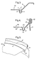
Figure 3 is a partial side section of the can end offigure 2 , prior to seaming; -
Figure 4 is a partial side section of the can end offigure 2 , after seaming to a can body; and -
Figure 5 is a sectioned perspective view of a seamed can end having two types of control features. - The can end of
figure 1 is a conventional beverage end shell 1 comprising aperipheral curl 2 which is connected to acentre panel 3 via a chuck wall 4 and anti-peaking reinforcing bead orcountersink 5. The centre panel has a score line 6 which defines an aperture for dispensing beverage. Atab 7 is fixed to thecentre panel 3 by a rivet 8, as is usual practice. Beads 9 are provided for stiffening the panel. - The can end of
figure 1 when attached by seaming to a can body which is filled with carbonated beverage, for example, is typically able to withstand an internal pressure of 6,75.105 Pa (98 psi) before buckling, 0,55.105 Pa (8 psi) above the required minimum buckle pressure of 6,2.105 Pa (90 psi). When the pressure approaches and exceeds this value, the circular shape of the periphery of the end will distort and become oval. Eventually the centre panel will be forced outwardly so that the countersink "unravels" and flips over an arc of its circumference. Whilst a can which is buckled in such a manner is unlikely to be acceptable to a consumer, the can end itself is still intact, thetab 7 is still accessible and there is no compromise to the sealing of the container by such failure which could result in leaking of the contents. - It has been found by the present Applicants, however, that where a container has an end which is, by virtue of its design, substantially stiffer and has greater hoop strength than that of
figure 1 , the buckle failure mode differs from that described above. Such a can end is that ofEP-B-0828663 , shown for reference infigures 2 to 4 . The can end 20 is attached to acan body 21 by adouble seam 22, as shown infigure 4 .Inner portion 23 of theseam 22, which is substantially upright, is connected to acountersink bead 25 by achuck wall 24. The countersink, oranti-peaking bead 25 has inner andouter walls inner wall 26 depending from thecentre panel 28 of the end. - Whilst the higher hoop strength exhibited by this can end is of great importance in maintaining the overall integrity of the container, the mode in which the can fails under severe abuse conditions may be unacceptable and even, on occasion, catastrophic. Typical failure modes may compromise the integrity of the can by pin hole(s) and/or splitting of the can end. In extreme cases, the
centre panel 28 is pushed outwardly by excessive internal pressure. As the panel moves outwardly, it pulls theinner wall 26 of theanti-peaking bead 25 with it. Theinner portion 23 ofseam 22 is "peeled" away from the rest of the seam as the can end is forced out. The explosive nature of this so-called "peaking" failure results in the formation of a bird's beak configuration with a pin hole at the apex of the "beak" where the force is concentrated in a single point at the base of thecountersink 25. - The Applicants have discovered that by providing the can end with a control feature, a preferential "soft" peak is obtainable when the can end fails. Although this means that the can end may fail at a lower buckle pressure, the softer, less explosive nature of the peak results in a failure mode without pin hole or tearing. The introduction of a control feature thus controls the failure mode and avoids concentration of the forces at a single point.
- Control features in accordance with the invention can take a variety of forms including one or more of the following with reference to
figures 3 and 4 but has to comprise at least a type A region or a type D region: - A. The radial position of the
outer wall 27 of the countersink bead may be increased; - B. The
chuck wall 24 may be coined or have indentations at or above approximately the mid-point such that this control feature is at the root of theseam 22 in the seamed can end (denoted as B'); - C. Coining of the inner shoulder (C) of the countersink or of the outer shoulder (C');
- D. A shelf may be made in the
outer wall 27 of the countersink bead. - When a type D region is at the lower part of the outer countersink wall, this may be equivalent to a type A control feature. Higher up the outer wall, a type D region takes the clear form of a shelf.
- In a preliminary trial of the present invention, the shell of
figures 2 to 4 was modified by a local groove in the outer wall of the countersink. This groove was ideally adjacent the handle of the tab so that any failure of the can end would be away from the score. Positioning either side of the tab or, indeed, at any position around the countersink was also considered possible. The groove was typically about 8 mm in arc length and was positioned approximately half way down the outer wall of the countersink bead, in the form of a shelf. Computer modelling has showed that the provision of such a groove resulted in a failure mode similar to that of a conventional can end such as that offigure 1 , with no leakage. - Modelling and bench testing has revealed that even better control of the failure mode was achievable when a pair of grooves were made at the base of the countersink outer wall. A variety of variables were modelled and then bench tested as follows:
depth of groove bottom of outer wall * gap between grooves 3mm to 6mm radial interference (depth of penetration into outer wall) 0.2mm to 0.4mm orientation behind (handle end of) tab 60° to tab left only 60° to tab right only 60° to tab left and right * This is equivalent to increasing the radial position of the countersink (anti-peaking) bead. - In bench testing of a small batch of cans using each of the above combinations, it was found that whilst the majority of cans leaked, the provision of a control feature controlled the position of peaking to the indentation site and all leaks were located on the peaks rather than on the tab rivet or score.
- In spite of the fact that the cans of the initial trial still leaked on peaking, the Application discovered that the incident of leakage was greatly reduced by a combination of types of control features which may, individually, exhibit unacceptable leaking on peaking. The following examples show how the failure mode can not only be focussed on a particular site on the can end but also be controlled such that the can also has acceptable buckle performance. In all of these further trials, cans were heated to 37,7°C (100°F) before carrying out the drop tests.
- Can ends were modified in the conversion press by expanding the countersink bead over a 60° arc at positions +/- 90° of the tab heel. These ends were then seamed onto filled cans and dropped vertically, tab end down, onto a steel plate, the sheet steel being inclined at 30°. This extreme test is non-standard and tested the cans for severe abuse performance. The tests used the Bruceton staircase analysis and results are set out in table 1, where P = standard peak and PS = peak and score burst.
- All cans tested peaked at the control feature without splitting. As with preliminary bench testing, the position of peaking was focussed on the indentation site.
- Can ends modified in this way were also tested by pressurising a can to which the end was seamed ("seamed end test"). These results are shown in table 2. Whilst the cans all peaked on the indentation site and were still openable after peaking, only 25% survived testing without leaking on the peak location.
TABLE 1 (Bruceton staircase test) Expanded countersink bead Drop test (onto 30° sheet steel) CAN HEIGHT
(")LEAK ON PEAK? PEAK ON CONTROL FEATURE? PEAK TYPE 1 5 N Y P 2 10 N Y PS 3 5 N Y P 4 10 N Y P 5 15 N Y PS 6 10 N Y PS 7 5 N Y P 8 6 N Y P 9 7 N Y P 10 8 N Y PS 11 7 N Y P 12 8 N Y PS 13 7 N Y P 14 8 N Y PS 15 7 N Y P TABLE 2 (SET test) CAN PRESSURE
(psi)SURVIVE? PEAK ON CONTROL FEATURE? OPENABLE? 1 95 N Y Y 2 93.4 Y Y Y 3 99.3 N Y Y 4 100.4 N Y Y Average 97.0 25% 100% 100% P = standard peak with no leak
PS = peaked and burst at the score - Further can ends were then modified in the conversion press both by expanding the countersink bead over a 60° arc at positions +/- 90° of the tab heel, and also by providing a indentation over a 50° arc at positions +/-90° in the upper chuck wall. These ends were then seamed onto filled cans and drop tested by dropping vertically, tab end down, onto a steel plate, the sheet steel being inclined at 30°. The results of the second tests are given in table 3, where again P = standard peak and PS = peak and score burst.
- The combination of a countersink bead expansion and indentation in the chuck wall increases the average height at which peaking occurs. The countersink bead expansion was found to act as a trigger and this combination of a trigger and chuck wall indentation controls the peaking better than a countersink bead expansion alone (example 1).
- Can ends modified in this way were also tested by pressurising a can to which the end was seamed ("seamed end test"). These results are shown in table 4.
- In the results of table 4, all the cans again peaked on the indentation site and were still openable after peaking. In addition, 100% survived testing without leaking on the peak location, supporting the Applicant's discovery that by combining two types of control feature, performance in terms of leak-free failure mode is dramatically improved.
TABLE 3 (Bruceton staircase test) Expanded countersink bead + chuck wall groove Drop test (onto 30° sheet steel) CAN HEIGHT
(")LEAK ON PEAK? ON CONTROL FEATURE? PEAK TYPE 1 5 N Y P 2 10 N Y P 3 15 Y Y P 4 12 Y Y P 5 11 N Y P 6 12 Y Y P 7 11 N Y P 8 12 Y Y P 9 11 N Y P 10 10 Y Y P 11 8 N Y PS 12 9 Y Y P 13 8 N Y P 14 9 Y Y P 15 8 N Y P TABLE 4 (SET test) CAN PRESSURE
(psi)SURVIVE? PEAK ON CONTROL FEATURE? OPENABLE? 1 93.7 Y Y Y 2 87 Y Y Y 3 93.2 Y Y Y 4 92.3 Y Y Y Average 91.6 100% 100% 100% - Can ends having an indentation in the upper chuck wall only (i.e. not in the countersink) were seamed to can bodies and then pressurised. Runs 1 to 8 had a single indentation behind the tab over an arc of about 40° to 50°. Runs 1-1 to 8-8 had indentations at +/- 90° and over a 50° arc. Mean results are given throughout. Peak location indicates the incidence of a peak on the control feature. The spacer details explain the degree of indentation in the chuck wall.
TABLE 5 (SET test) RUN Reversal pressure (psi) % peak on control feature Survival Openable Radial spacer
(mm)Indent space 1 99.03 100% 25% 100% 0.5 8.75 2 101.7 75% 50% 100% 0 8.75 3 92.48 100% 75% 75% 0 9.25 4 91.3 100% 25% 75% 0.5 9.25 5 101.83 100% 75% 100% 0.5 10.75 6 103.2 100% 100% 100% 0 10.75 7 94.65 100% 50% 100% 0 11.25 8 93.45 100% 75% 100% 0.5 11.25 1-1 101.45 100% 75% 75% 0.5 8.75 2-2 101.83 75% 75% 100% 0 8.75 3-3 92.35 100% 75% 100% 0 9.25 4-4 89.6 100% 25% 100% 0.5 9.25 5-5 102.0 100% 75% 100% 0.5 10.75 6-6 103.95 75% 50% 100% 0 10.75 7-7 94.98 100% 75% 100% 0 11.25 8-8 95.8 100% 75% 100% 0.5 11.25 CONTROL 105.98 N/ A 25% 100% N/A N/A - Further trials were conducted to confirm the effect of expansion of the countersink radius and the indentation in the upper chuck wall, both separately and together. Unmodified can ends were tested by way of control. The results are shown in tables 6 and 7.
- The chuck wall indentations comprised a indentation on each side of the tab, set at 90° to the tab. Spacer conditions were as in example 3, but with a 9 mm indent ring spacer (rather than 8.75 mm).
- The countersink "trigger" comprised a single bead expansion within the arc of the chuck wall indentation and centred on the same diameter (arc mid-point). This bead expansion was selected to trigger a peak within the chuck wall indentation as identified in example 2.
- The control can ends give very low survival figures in both drop tests and seamed end testing (SET), i.e. the control can ends leak when they peak. The chuck wall indentation alone gives good hot drop (100°F) and SET performance but seems to have higher incidence of score bursts during hot drop testing. The countersink ("c'sk") bead trigger creates a very symmetric end shape from the hot drop test and is very effective in determining the peak location. The countersink trigger reduces the SET performance to 6,1.105 Pa (89 psi) average, but this is believed to be attributable to the tooling used to create the indentations. In general "1" means yes and "0" means no, except in position in which 1 indicates the position of peak on the control feature.
TABLE 6 (Bruceton staircase comparing unmodified with various modified can ends) Unmodified control C'sk bead trigger only Chuck wall only Both features Height Leak ? Leak type Height Leak ? Position? Leak Type Height Leak ? Position? Leak Type Height Leak ? Position? Leak Type 5 y p 5 Y 1 p x 2 5 n 0 p x 2 5 Y 1 clamshell 4 y p 4 Y 1 p x 2 5 y 1 p 4 N 1 p x 2 3 y p 3 Y 1 p x 2 4 n 1 p 5 Y 1 p x 2 2 y p 2 Y 1 p x 2 5 n 1 p 4 N 1 p x 2 1 y score burst 1 Y 1 score burst 6 n 1 p 5 N 1 p x 2 1 n none 1 Y 1 score burst 7 y 1 score burst 6 Y 1 p x 2 1 n p 1 N 1 score burst 6 y 1 p x 2 5 N 1 p x 2 2 y p 2 N 1 score burst 5 n 1 p x 2 6 N 1 p x 2 1 y p x 2 3 Y 1 p x 2 6 y 1 p x 2 7 Y 1 p x 2 1 y score burst 2 Y2 1 p x 2 5 n 1 p 6 Y 1 p x 2 1 y p 1 Y 0 p x 2 6 n 1 p x 2 5 N 1 p x 2 1 n p 1 Y 1 score burst 7 n 1 p x 2 6 N 1 p x 2 2 n p 1 N 1 p x 2 8 n 1 p 7 Y 1 p x 2 3 y p 2 Y 1 score burst 9 n 1 score burst 6 Y 1 p x 2 2 n p x 2 1 N 0 p x 2 9 n 1 score burst 5 N 1 p x 2 3 y p 1 N 1 score burst 9 y 1 p x 2 6 N 1 p x 2 2 y p 2 Y 1 p x 2 8 n 1 p x 2 7 N 1 p x 2 1 n none 1 Y 1 p x 1 9 y 1 score burst 8 N 1 p x 2 2 n p 1 N 1 p x 1 8 n 1 p x 2 9 Y 1 p x 2 3 n p 2 Y 1 p x 1 9 n 1 p x 2 8 Y 1 p x 2 4 y p x 2 1 Y 1 p x 1 10 y 1 p x 2 7 N 1 p x 2 3 n p 1 Y 1 p x 1 9 n 1 p x 2 8 N 1 p x 2 4 n p 1 Y 1 score burst 11 n 1 p x 2 9 Y 1 p x 2 5 y p 1 Y 1 score burst 12 n 1 p x 2 8 Y 1 p x 2 4 y p 1 Y 1 score burst 13 n 1 p x 2 7 Y 1 clamshell 3 y p 1 Y 1 score burst 14 n 1 p x 2 6 Y 1 p x 2 2 y p x 2 1 Y 1 p x 2 15 n 1 p x 2 5 N 1 p x 2 1 y p x 2 1 Y 1 score burst 15 y2 1 p x 2 6 Y 1 p x 2 1 n p 1 Y 1 score burst 14 n 1 p x 2 5 N 1 p x 2 2 n p 93% 97% 100% TABLE 7 (SET comparisons of unmodified with modified can ends) UNMODIFIED Can 1 Can 2 Can 3 Can 4 Can 5 Can 6 Can 7 Can 8 Can 9 Can 10 Average BUCKLE PRESSURE (psi) 103.4 101.1 99.7 101.6 104.4 102.9 98.3 97.9 98.3 108 102 POSITION ? n/a n/a n/a n/a n/a n/a n/a n/a n/a n/a n/a SURVIVED ? 1 0 0 0 0 0 0 0 0 1 20% OPENS ? 1 1 1 1 1 0 1 1 1 1 90 % C'sk BEAD TRIGGER DENT ONLY Can 1 Can 2 Can 3 Can 4 Can 5 Can 6 Can 7 Can 8 Can 9 Can 10 Average BUCKLE PRESSURE (psi) 88.4 91.9 92.5 91.7 91.2 91.4 91.1 1 92 95 92.7 92 POSITION? 1 1 1 1 1 1 1 1 1 1 100% SURVIVED ? 0 0 0 0 0 0 0 0 0 0 0% OPENS ? 1 1 1 1 1 1 1 1 1 1 100 % CHUCK WALL DENT ONLY Can 1 Can 2 Can 3 Can 4 Can 5 Can 6 Can 7 Can 8 Can 9 Can 10 Average BUCKLE PRESSURE (psi) 96.6 95.7 92.7 93.7 94.3 94.6 92 95.1 93.7 95.5 94 POSITION? 1 1 1 1 1 1 1 1 1 1 100 % SURVIVED ? 1 1 1 1 1 1 1 0 1 1 90% OPENS ? 1 1 1 1 1 1 1 0 1 1 90% BOTH DENTS Can 1 Can 2 Can 3 Can 4 Can 5 Can 6 Can 7 Can 8 Can 9 Average BUCKLE PRESSURE (psi) 86.6 90.5 87.7 87.6 88.5 92.7 90.3 86.3 87.5 89 POSITION? 1 1 1 1 1 1 1 1 1 100 % SURVIVED ? 1 1 1 1 1 1 1 1 1 100% OPENS ? 1 1 1 0 1 1 1 1 1 89% - Further seamed end tests were carried out on both unmodified can ends ("control samples") and can ends having a 360° control feature in the form of a shelf in the outer wall of the countersink bead. Results of these trials are given in table 8. Buckle pressure performance was well above the 6,2.105 Pa (90 psi) industry standard for all cans, both standard and modified. Only 25% of the control samples survived testing without leaking, whereas 100% of the cans having a control feature (circumferential shelf in the countersink bead) passed the test without leaking.
- The invention has been described above by way of example only and numerous changes and/or permutations may be made within the scope of the invention as defined by the appended claims. It should also be noted that the control features of the invention are particularly intended for use on beverage can ends which are to be fixed to a can body and thereby subjected to internal pressure. Furthermore, the control features may be used on can ends having any chuck wall angle whether conventional (less than 15°) or larger, such as that of
EP-B-0828663 , i.e. 30° to 60°.TABLE 8 Control Samples Shelf in Bead Buckle Buckle Leak Pressure (psi) Pressure (psi) 102.6 n 98.1 n 102.3 n 104.1 n 105.6 y 102.3 n 105.6 y 96.8 n 101.5 n 103.4 n 101.7 y 103.5 n 102.5 y 104 n 104.6 y 103.5 n 107 n 99.8 n 103.4 y 105 n 103.5 y 103.6 n 104.2 y 104.1 n 103.6 n 103.9 n 102.2 n 104 n 103 n 102.2 n 103 y 103.1 n 103.5 y 105.5 n 105.1 y 104.5 n 102.8 y 101.9 n 102.8 y 104.1 n 104.7 y 100.5 n 103.8 y 103.2 n 103.8 y 102.3 n 105.9 y 101.9 n 104.5 y 105.7 n 103.3 y 105.6 n 103.3 y 98.6 n 104.5 y 101.3 n
Claims (9)
- A can end shell (20) comprising a centre panel, a countersink bead (25), an inclined chuck wall portion (24), a seaming panel (22), and one or more control features for controlling the failure mode of the can end when seamed to a can body (21), each control feature extending around an arc of up to 360° of part of the countersink bead (25) and/or the chuck wall (24) characterized in that, at least one control feature comprises an expansion of the outer wall (27) of the countersink bead (25), or a shelf in the outer wall (27) of the countersink bead (25).
- An end shell (20) according to claim 1, including a control feature which comprises an indentation in the chuck wall portion (24).
- An end shell (20) according to claim 1 or claim 2, in which a control feature extends over an arc behind the heel of a tab (7) fixed to the can end, and centred on a diameter through the tab axis.
- An end shell (20) according to claim 1, having a control feature on each side of a diameter through the tab central axis and each extending around an arc of the can end.
- An end shell (20) according to any one of claims 1 to 4, in which each control feature comprises at least an expansion of the countersink bead (27) and an indentation in the chuck wall (24), extending around an arc centred on the same can diameter.
- An end shell (20) according to claim 5, in which the arc length of the bead expansion is less than the arc length of the chuck wall indentation, such that the bead expansion acts as a trigger.
- An end shell (20) according to claim 1, in which the control feature extends around the whole circumference of the end shell (20).
- An end shell (20) according to any one of claims 1 to 10, in which the or each control feature is made in either a shell press or a conversion press or a combination of these.
- A can comprising a can body (21) and a can end (20) according to any one of claims 1 to 8, the can end (20) being joined to the can body (21) by a double seam (22).
Priority Applications (1)
| Application Number | Priority Date | Filing Date | Title |
|---|---|---|---|
| EP03722438A EP1497054B1 (en) | 2002-04-22 | 2003-04-10 | Can end |
Applications Claiming Priority (4)
| Application Number | Priority Date | Filing Date | Title |
|---|---|---|---|
| EP02252800A EP1361164A1 (en) | 2002-04-22 | 2002-04-22 | Can end |
| EP02252800 | 2002-04-22 | ||
| PCT/EP2003/003716 WO2003089167A1 (en) | 2002-04-22 | 2003-04-10 | Can end |
| EP03722438A EP1497054B1 (en) | 2002-04-22 | 2003-04-10 | Can end |
Publications (2)
| Publication Number | Publication Date |
|---|---|
| EP1497054A1 EP1497054A1 (en) | 2005-01-19 |
| EP1497054B1 true EP1497054B1 (en) | 2008-11-26 |
Family
ID=29225723
Family Applications (2)
| Application Number | Title | Priority Date | Filing Date |
|---|---|---|---|
| EP02252800A Withdrawn EP1361164A1 (en) | 2002-04-22 | 2002-04-22 | Can end |
| EP03722438A Revoked EP1497054B1 (en) | 2002-04-22 | 2003-04-10 | Can end |
Family Applications Before (1)
| Application Number | Title | Priority Date | Filing Date |
|---|---|---|---|
| EP02252800A Withdrawn EP1361164A1 (en) | 2002-04-22 | 2002-04-22 | Can end |
Country Status (14)
| Country | Link |
|---|---|
| US (2) | US20040238546A1 (en) |
| EP (2) | EP1361164A1 (en) |
| JP (1) | JP4280645B2 (en) |
| CN (1) | CN100393443C (en) |
| AT (1) | ATE415217T1 (en) |
| AU (1) | AU2003229636B2 (en) |
| BR (1) | BR0309446B1 (en) |
| CA (1) | CA2482984C (en) |
| DE (1) | DE60324910D1 (en) |
| ES (1) | ES2318126T3 (en) |
| MX (1) | MXPA04010456A (en) |
| RU (1) | RU2319571C2 (en) |
| WO (1) | WO2003089167A1 (en) |
| ZA (1) | ZA200408419B (en) |
Families Citing this family (47)
| Publication number | Priority date | Publication date | Assignee | Title |
|---|---|---|---|---|
| US6419110B1 (en) | 2001-07-03 | 2002-07-16 | Container Development, Ltd. | Double-seamed can end and method for forming |
| EP1361164A1 (en) | 2002-04-22 | 2003-11-12 | Crown Cork & Seal Technologies Corporation | Can end |
| US7591392B2 (en) | 2002-04-22 | 2009-09-22 | Crown Packaging Technology, Inc. | Can end |
| USD600116S1 (en) * | 2003-09-19 | 2009-09-15 | Gabe Cherian | Lid with pull tab |
| USD612724S1 (en) * | 2003-09-19 | 2010-03-30 | Gabe Cherian | Lid with pull tab |
| CA2574973C (en) | 2004-07-29 | 2014-05-06 | Ball Corporation | Method and apparatus for shaping a metallic container end closure |
| USD579771S1 (en) * | 2004-09-14 | 2008-11-04 | Gabe Cherian | Lid with pull tab |
| US9580204B2 (en) * | 2004-09-14 | 2017-02-28 | Gabe Cherian | PT2 pull tab lids stacking |
| WO2006036934A2 (en) | 2004-09-27 | 2006-04-06 | Ball Corporation | Container end closure |
| WO2006123637A1 (en) * | 2005-05-17 | 2006-11-23 | Toyo Seikan Kaisha, Ltd. | Square can and method and device for double-seaming the same |
| DE102005024219B3 (en) * | 2005-05-25 | 2006-07-13 | Ball Packaging Europe Gmbh | Lid with surround to connect it to container using guide columns or pins jutting out vertically from lid which can be used to hold other parts if required |
| ATE499304T1 (en) | 2005-05-25 | 2011-03-15 | Ball Packaging Europe Gmbh | LID WITH GUIDE COLUMNS FOR A CONTAINER |
| US7506779B2 (en) | 2005-07-01 | 2009-03-24 | Ball Corporation | Method and apparatus for forming a reinforcing bead in a container end closure |
| US8109406B2 (en) * | 2006-10-26 | 2012-02-07 | Charles Chang | Beverage container construction |
| US8875936B2 (en) | 2007-04-20 | 2014-11-04 | Rexam Beverage Can Company | Can end with negatively angled wall |
| US8011527B2 (en) * | 2007-08-10 | 2011-09-06 | Rexam Beverage Can Company | Can end with countersink |
| US8973780B2 (en) | 2007-08-10 | 2015-03-10 | Rexam Beverage Can Company | Can end with reinforcing bead |
| CN101445170B (en) * | 2008-11-24 | 2012-09-05 | 波尔亚太(佛山)金属容器有限公司 | Method for preparing printed lid of aluminum easy open can |
| US20100213194A1 (en) * | 2009-02-21 | 2010-08-26 | Junsong Liu | Pop Can Beak Spout Design |
| US8939308B2 (en) | 2009-09-04 | 2015-01-27 | Crown Packaging Technology, Inc. | Full aperture beverage end |
| CA2778711C (en) | 2009-10-23 | 2015-09-22 | Barry W. Chapin | Beverage can marketing device |
| US9566634B2 (en) | 2010-06-07 | 2017-02-14 | Rexam Beverage Can Company | Can end produced from downgauged blank |
| USD640141S1 (en) * | 2010-07-09 | 2011-06-21 | Chapin Barry W | Countersink groove cover on a beverage can |
| EP2409925B1 (en) * | 2010-07-19 | 2012-12-19 | Red Bull GmbH | Resealable container lid, container, in particular drink cans, containing the resealable container lid, method for producing such containers and application of the container lid |
| USD669781S1 (en) | 2010-08-23 | 2012-10-30 | Crown Packaging Technology, Inc. | Full transversely oriented oval aperture can |
| USD685266S1 (en) | 2010-10-18 | 2013-07-02 | Silgan Containers Llc | Can end |
| USD653109S1 (en) | 2010-10-18 | 2012-01-31 | Stolle Machinery Company, Llc | Can end |
| US9550604B2 (en) | 2010-10-18 | 2017-01-24 | Silgan Containers Llc | Can end with strengthening bead configuration |
| US8727169B2 (en) | 2010-11-18 | 2014-05-20 | Ball Corporation | Metallic beverage can end closure with offset countersink |
| AU2012271811A1 (en) | 2011-06-14 | 2013-05-02 | Crown Packaging Technology, Inc. | Methods and system for forming high-strength beverage can ends of aluminum magnesium alloy and such can ends |
| US8939695B2 (en) | 2011-06-16 | 2015-01-27 | Sonoco Development, Inc. | Method for applying a metal end to a container body |
| US8998027B2 (en) | 2011-09-02 | 2015-04-07 | Sonoco Development, Inc. | Retort container with thermally fused double-seamed or crimp-seamed metal end |
| GB201118284D0 (en) * | 2011-10-21 | 2011-12-07 | Crown Packaging Technology Inc | Can end |
| US10131455B2 (en) | 2011-10-28 | 2018-11-20 | Sonoco Development, Inc. | Apparatus and method for induction sealing of conveyed workpieces |
| US20130105499A1 (en) * | 2011-10-28 | 2013-05-02 | Sonoco Development, Inc. | Three-Piece Can and Method of Making Same |
| GB201205243D0 (en) | 2012-03-26 | 2012-05-09 | Kraft Foods R & D Inc | Packaging and method of opening |
| US10399139B2 (en) | 2012-04-12 | 2019-09-03 | Sonoco Development, Inc. | Method of making a retort container |
| US9821928B2 (en) | 2012-05-14 | 2017-11-21 | Rexam Beverage Can Company | Can end |
| GB2510623B (en) * | 2013-02-11 | 2015-10-21 | Crown Packaging Technology Inc | Seated end process |
| GB2511559B (en) | 2013-03-07 | 2018-11-14 | Mondelez Uk R&D Ltd | Improved Packaging and Method of Forming Packaging |
| GB2511560B (en) | 2013-03-07 | 2018-11-14 | Mondelez Uk R&D Ltd | Improved Packaging and Method of Forming Packaging |
| US9114451B2 (en) | 2013-03-15 | 2015-08-25 | Ball Corporation | Container end closure with buckle control feature |
| JP2016520026A (en) | 2013-05-31 | 2016-07-11 | クラウン パッケイジング テクノロジー インコーポレイテッド | Beverage can end having an arcuate panel wall and a curved transition wall |
| US9714114B2 (en) | 2013-11-08 | 2017-07-25 | Crown Packaging Technology, Inc. | Full aperture can end |
| USD763969S1 (en) * | 2015-06-16 | 2016-08-16 | Claudius Jeager | Flying disk toy |
| CN107883583A (en) * | 2016-09-29 | 2018-04-06 | 青岛经济技术开发区海尔热水器有限公司 | Shell of water heater and water heater |
| USD956555S1 (en) * | 2017-12-07 | 2022-07-05 | Crown Packaging Technology, Inc. | Cap with tab |
Family Cites Families (21)
| Publication number | Priority date | Publication date | Assignee | Title |
|---|---|---|---|---|
| US3441170A (en) * | 1967-03-03 | 1969-04-29 | Continental Can Co | Coined bead for improved fill characteristics |
| US3843014A (en) * | 1973-03-16 | 1974-10-22 | Pechiney Ugine Kuhlmann | Container cover |
| US4808052A (en) * | 1986-07-28 | 1989-02-28 | Redicon Corporation | Method and apparatus for forming container end panels |
| US4832223A (en) * | 1987-07-20 | 1989-05-23 | Ball Corporation | Container closure with increased strength |
| TR24070A (en) * | 1987-10-15 | 1991-02-28 | Bekaert Sa Nv | REINFORCED SERIES FOR RUBBER TIRES. |
| US4928844A (en) * | 1989-04-14 | 1990-05-29 | Aluminum Company Of America | Pressure release for carbonated beverage containers |
| RU2019349C1 (en) * | 1991-12-11 | 1994-09-15 | Василий Васильевич Онищенко | Method of making cylindrical tanks |
| JP2570560B2 (en) * | 1992-12-08 | 1997-01-08 | 東洋製罐株式会社 | Easy opening can lid |
| US5645189A (en) * | 1994-11-21 | 1997-07-08 | Metal Container Corporation | Container end having annular panel with non-uniform radius of curvature |
| GB9510515D0 (en) * | 1995-05-24 | 1995-07-19 | Metal Box Plc | Containers |
| WO1998037995A1 (en) * | 1997-02-27 | 1998-09-03 | Buhrke Tech International, Inc. | Reduced gauge steel can end |
| AU737437B2 (en) * | 1997-11-12 | 2001-08-16 | James Lee Gardiner | Beverage container |
| US6089072A (en) * | 1998-08-20 | 2000-07-18 | Crown Cork & Seal Technologies Corporation | Method and apparatus for forming a can end having an improved anti-peaking bead |
| EP1470052B1 (en) | 1999-12-08 | 2012-09-19 | Ball Corporation | Metallic beverage can end with improved chuck wall and countersink |
| USD452155S1 (en) * | 2000-08-15 | 2001-12-18 | Container Development Ltd | Can end |
| US6419110B1 (en) * | 2001-07-03 | 2002-07-16 | Container Development, Ltd. | Double-seamed can end and method for forming |
| US6748789B2 (en) * | 2001-10-19 | 2004-06-15 | Rexam Beverage Can Company | Reformed can end for a container and method for producing same |
| USD480304S1 (en) * | 2002-01-04 | 2003-10-07 | Container Development, Ltd. | Can end |
| USD471453S1 (en) * | 2002-01-04 | 2003-03-11 | Container Development, Ltd | Can end |
| EP1361164A1 (en) | 2002-04-22 | 2003-11-12 | Crown Cork & Seal Technologies Corporation | Can end |
| US6915553B2 (en) * | 2003-02-19 | 2005-07-12 | Rexam Beverage Can Company | Seaming apparatus and method for cans |
-
2002
- 2002-04-22 EP EP02252800A patent/EP1361164A1/en not_active Withdrawn
-
2003
- 2003-04-10 MX MXPA04010456A patent/MXPA04010456A/en active IP Right Grant
- 2003-04-10 WO PCT/EP2003/003716 patent/WO2003089167A1/en not_active Ceased
- 2003-04-10 AT AT03722438T patent/ATE415217T1/en not_active IP Right Cessation
- 2003-04-10 CN CNB038090155A patent/CN100393443C/en not_active Expired - Lifetime
- 2003-04-10 CA CA2482984A patent/CA2482984C/en not_active Expired - Lifetime
- 2003-04-10 DE DE60324910T patent/DE60324910D1/en not_active Expired - Lifetime
- 2003-04-10 EP EP03722438A patent/EP1497054B1/en not_active Revoked
- 2003-04-10 RU RU2004133891/02A patent/RU2319571C2/en active
- 2003-04-10 BR BRPI0309446-4A patent/BR0309446B1/en active IP Right Grant
- 2003-04-10 ES ES03722438T patent/ES2318126T3/en not_active Expired - Lifetime
- 2003-04-10 AU AU2003229636A patent/AU2003229636B2/en not_active Expired
- 2003-04-10 JP JP2003585908A patent/JP4280645B2/en not_active Expired - Fee Related
-
2004
- 2004-02-03 US US10/770,791 patent/US20040238546A1/en not_active Abandoned
- 2004-10-18 ZA ZA2004/08419A patent/ZA200408419B/en unknown
-
2006
- 2006-09-28 US US11/540,238 patent/US7370774B2/en not_active Expired - Lifetime
Also Published As
| Publication number | Publication date |
|---|---|
| ES2318126T3 (en) | 2009-05-01 |
| CA2482984C (en) | 2012-06-26 |
| JP2006514595A (en) | 2006-05-11 |
| EP1497054A1 (en) | 2005-01-19 |
| EP1361164A1 (en) | 2003-11-12 |
| MXPA04010456A (en) | 2005-07-14 |
| BR0309446A (en) | 2005-02-09 |
| CN1646243A (en) | 2005-07-27 |
| US20040238546A1 (en) | 2004-12-02 |
| RU2319571C2 (en) | 2008-03-20 |
| BR0309446B1 (en) | 2014-10-07 |
| RU2004133891A (en) | 2005-09-10 |
| WO2003089167A1 (en) | 2003-10-30 |
| ATE415217T1 (en) | 2008-12-15 |
| DE60324910D1 (en) | 2009-01-08 |
| CA2482984A1 (en) | 2003-10-30 |
| US7370774B2 (en) | 2008-05-13 |
| JP4280645B2 (en) | 2009-06-17 |
| AU2003229636B2 (en) | 2008-06-26 |
| AU2003229636A1 (en) | 2003-11-03 |
| US20070029324A1 (en) | 2007-02-08 |
| ZA200408419B (en) | 2005-11-30 |
| HK1080782A1 (en) | 2006-05-04 |
| CN100393443C (en) | 2008-06-11 |
Similar Documents
| Publication | Publication Date | Title |
|---|---|---|
| AU2003229636B2 (en) | Can end | |
| US8157119B2 (en) | Can end | |
| EP1441957B1 (en) | Reformed can end and method therefore | |
| JP3418628B2 (en) | Pressure-resistant sheet metal closing member, molding method and molding apparatus for the member | |
| EP3647217B1 (en) | Concave can end | |
| US20040094559A1 (en) | Can end, tooling for manufacture of the can end and seaming chuck adapted to affix a converted can end to a can body | |
| AU2002347836A1 (en) | Reformed can end and method therefore | |
| US7772518B2 (en) | Reinforced can end—can body joints with laser seaming | |
| KR20250044297A (en) | Fully open can end | |
| HK1080782B (en) | Can end |
Legal Events
| Date | Code | Title | Description |
|---|---|---|---|
| PUAI | Public reference made under article 153(3) epc to a published international application that has entered the european phase |
Free format text: ORIGINAL CODE: 0009012 |
|
| 17P | Request for examination filed |
Effective date: 20041004 |
|
| AK | Designated contracting states |
Kind code of ref document: A1 Designated state(s): AT BE BG CH CY CZ DE DK EE ES FI FR GB GR HU IE IT LI LU MC NL PT RO SE SI SK TR |
|
| AX | Request for extension of the european patent |
Extension state: AL LT LV MK |
|
| GRAP | Despatch of communication of intention to grant a patent |
Free format text: ORIGINAL CODE: EPIDOSNIGR1 |
|
| GRAS | Grant fee paid |
Free format text: ORIGINAL CODE: EPIDOSNIGR3 |
|
| GRAA | (expected) grant |
Free format text: ORIGINAL CODE: 0009210 |
|
| AK | Designated contracting states |
Kind code of ref document: B1 Designated state(s): AT BE BG CH CY CZ DE DK EE ES FI FR GB GR HU IE IT LI LU MC NL PT RO SE SI SK TR |
|
| REG | Reference to a national code |
Ref country code: GB Ref legal event code: FG4D |
|
| REG | Reference to a national code |
Ref country code: CH Ref legal event code: EP |
|
| REG | Reference to a national code |
Ref country code: IE Ref legal event code: FG4D |
|
| REF | Corresponds to: |
Ref document number: 60324910 Country of ref document: DE Date of ref document: 20090108 Kind code of ref document: P |
|
| REG | Reference to a national code |
Ref country code: SE Ref legal event code: TRGR |
|
| REG | Reference to a national code |
Ref country code: GR Ref legal event code: EP Ref document number: 20090400367 Country of ref document: GR |
|
| PG25 | Lapsed in a contracting state [announced via postgrant information from national office to epo] |
Ref country code: AT Free format text: LAPSE BECAUSE OF FAILURE TO SUBMIT A TRANSLATION OF THE DESCRIPTION OR TO PAY THE FEE WITHIN THE PRESCRIBED TIME-LIMIT Effective date: 20081126 |
|
| REG | Reference to a national code |
Ref country code: ES Ref legal event code: FG2A Ref document number: 2318126 Country of ref document: ES Kind code of ref document: T3 |
|
| PG25 | Lapsed in a contracting state [announced via postgrant information from national office to epo] |
Ref country code: SI Free format text: LAPSE BECAUSE OF FAILURE TO SUBMIT A TRANSLATION OF THE DESCRIPTION OR TO PAY THE FEE WITHIN THE PRESCRIBED TIME-LIMIT Effective date: 20081126 Ref country code: FI Free format text: LAPSE BECAUSE OF FAILURE TO SUBMIT A TRANSLATION OF THE DESCRIPTION OR TO PAY THE FEE WITHIN THE PRESCRIBED TIME-LIMIT Effective date: 20081126 |
|
| PG25 | Lapsed in a contracting state [announced via postgrant information from national office to epo] |
Ref country code: RO Free format text: LAPSE BECAUSE OF FAILURE TO SUBMIT A TRANSLATION OF THE DESCRIPTION OR TO PAY THE FEE WITHIN THE PRESCRIBED TIME-LIMIT Effective date: 20081126 Ref country code: EE Free format text: LAPSE BECAUSE OF FAILURE TO SUBMIT A TRANSLATION OF THE DESCRIPTION OR TO PAY THE FEE WITHIN THE PRESCRIBED TIME-LIMIT Effective date: 20081126 Ref country code: DK Free format text: LAPSE BECAUSE OF FAILURE TO SUBMIT A TRANSLATION OF THE DESCRIPTION OR TO PAY THE FEE WITHIN THE PRESCRIBED TIME-LIMIT Effective date: 20081126 Ref country code: BG Free format text: LAPSE BECAUSE OF FAILURE TO SUBMIT A TRANSLATION OF THE DESCRIPTION OR TO PAY THE FEE WITHIN THE PRESCRIBED TIME-LIMIT Effective date: 20090226 |
|
| PG25 | Lapsed in a contracting state [announced via postgrant information from national office to epo] |
Ref country code: PT Free format text: LAPSE BECAUSE OF FAILURE TO SUBMIT A TRANSLATION OF THE DESCRIPTION OR TO PAY THE FEE WITHIN THE PRESCRIBED TIME-LIMIT Effective date: 20090427 Ref country code: CZ Free format text: LAPSE BECAUSE OF FAILURE TO SUBMIT A TRANSLATION OF THE DESCRIPTION OR TO PAY THE FEE WITHIN THE PRESCRIBED TIME-LIMIT Effective date: 20081126 |
|
| PLBI | Opposition filed |
Free format text: ORIGINAL CODE: 0009260 |
|
| PLAX | Notice of opposition and request to file observation + time limit sent |
Free format text: ORIGINAL CODE: EPIDOSNOBS2 |
|
| PG25 | Lapsed in a contracting state [announced via postgrant information from national office to epo] |
Ref country code: SK Free format text: LAPSE BECAUSE OF FAILURE TO SUBMIT A TRANSLATION OF THE DESCRIPTION OR TO PAY THE FEE WITHIN THE PRESCRIBED TIME-LIMIT Effective date: 20081126 |
|
| 26 | Opposition filed |
Opponent name: ROTHFUSS, WILLI Effective date: 20090824 |
|
| REG | Reference to a national code |
Ref country code: CH Ref legal event code: PL |
|
| NLR1 | Nl: opposition has been filed with the epo |
Opponent name: ROTHFUSS, WILLI |
|
| PG25 | Lapsed in a contracting state [announced via postgrant information from national office to epo] |
Ref country code: LI Free format text: LAPSE BECAUSE OF NON-PAYMENT OF DUE FEES Effective date: 20090430 Ref country code: CH Free format text: LAPSE BECAUSE OF NON-PAYMENT OF DUE FEES Effective date: 20090430 |
|
| PLAF | Information modified related to communication of a notice of opposition and request to file observations + time limit |
Free format text: ORIGINAL CODE: EPIDOSCOBS2 |
|
| PLBB | Reply of patent proprietor to notice(s) of opposition received |
Free format text: ORIGINAL CODE: EPIDOSNOBS3 |
|
| PG25 | Lapsed in a contracting state [announced via postgrant information from national office to epo] |
Ref country code: MC Free format text: LAPSE BECAUSE OF NON-PAYMENT OF DUE FEES Effective date: 20090430 |
|
| PG25 | Lapsed in a contracting state [announced via postgrant information from national office to epo] |
Ref country code: LU Free format text: LAPSE BECAUSE OF NON-PAYMENT OF DUE FEES Effective date: 20090410 |
|
| PG25 | Lapsed in a contracting state [announced via postgrant information from national office to epo] |
Ref country code: HU Free format text: LAPSE BECAUSE OF FAILURE TO SUBMIT A TRANSLATION OF THE DESCRIPTION OR TO PAY THE FEE WITHIN THE PRESCRIBED TIME-LIMIT Effective date: 20090527 |
|
| PG25 | Lapsed in a contracting state [announced via postgrant information from national office to epo] |
Ref country code: TR Free format text: LAPSE BECAUSE OF FAILURE TO SUBMIT A TRANSLATION OF THE DESCRIPTION OR TO PAY THE FEE WITHIN THE PRESCRIBED TIME-LIMIT Effective date: 20081126 |
|
| PG25 | Lapsed in a contracting state [announced via postgrant information from national office to epo] |
Ref country code: CY Free format text: LAPSE BECAUSE OF FAILURE TO SUBMIT A TRANSLATION OF THE DESCRIPTION OR TO PAY THE FEE WITHIN THE PRESCRIBED TIME-LIMIT Effective date: 20081126 |
|
| PLCK | Communication despatched that opposition was rejected |
Free format text: ORIGINAL CODE: EPIDOSNREJ1 |
|
| APBM | Appeal reference recorded |
Free format text: ORIGINAL CODE: EPIDOSNREFNO |
|
| APBP | Date of receipt of notice of appeal recorded |
Free format text: ORIGINAL CODE: EPIDOSNNOA2O |
|
| APAH | Appeal reference modified |
Free format text: ORIGINAL CODE: EPIDOSCREFNO |
|
| PLAB | Opposition data, opponent's data or that of the opponent's representative modified |
Free format text: ORIGINAL CODE: 0009299OPPO |
|
| R26 | Opposition filed (corrected) |
Opponent name: ROTHFUSS, WILLI Effective date: 20090824 |
|
| REG | Reference to a national code |
Ref country code: DE Ref legal event code: R082 Ref document number: 60324910 Country of ref document: DE Representative=s name: RAINER CALLIES, DE Ref country code: DE Ref legal event code: R082 Ref document number: 60324910 Country of ref document: DE Representative=s name: CALLIES, RAINER, DIPL.-PHYS. DR.RER.NAT., DE |
|
| APAH | Appeal reference modified |
Free format text: ORIGINAL CODE: EPIDOSCREFNO |
|
| APAH | Appeal reference modified |
Free format text: ORIGINAL CODE: EPIDOSCREFNO |
|
| REG | Reference to a national code |
Ref country code: FR Ref legal event code: PLFP Year of fee payment: 14 |
|
| REG | Reference to a national code |
Ref country code: DE Ref legal event code: R103 Ref document number: 60324910 Country of ref document: DE Ref country code: DE Ref legal event code: R064 Ref document number: 60324910 Country of ref document: DE |
|
| PGFP | Annual fee paid to national office [announced via postgrant information from national office to epo] |
Ref country code: NL Payment date: 20160420 Year of fee payment: 14 |
|
| APBU | Appeal procedure closed |
Free format text: ORIGINAL CODE: EPIDOSNNOA9O |
|
| PGFP | Annual fee paid to national office [announced via postgrant information from national office to epo] |
Ref country code: DE Payment date: 20160421 Year of fee payment: 14 Ref country code: IE Payment date: 20160421 Year of fee payment: 14 Ref country code: GB Payment date: 20160421 Year of fee payment: 14 Ref country code: ES Payment date: 20160413 Year of fee payment: 14 |
|
| RDAF | Communication despatched that patent is revoked |
Free format text: ORIGINAL CODE: EPIDOSNREV1 |
|
| RDAG | Patent revoked |
Free format text: ORIGINAL CODE: 0009271 |
|
| STAA | Information on the status of an ep patent application or granted ep patent |
Free format text: STATUS: PATENT REVOKED |
|
| PGFP | Annual fee paid to national office [announced via postgrant information from national office to epo] |
Ref country code: FR Payment date: 20160421 Year of fee payment: 14 Ref country code: BE Payment date: 20160420 Year of fee payment: 14 Ref country code: IT Payment date: 20160426 Year of fee payment: 14 |
|
| 27W | Patent revoked |
Effective date: 20160628 |
|
| GBPR | Gb: patent revoked under art. 102 of the ep convention designating the uk as contracting state |
Effective date: 20160628 |
|
| PGFP | Annual fee paid to national office [announced via postgrant information from national office to epo] |
Ref country code: GR Payment date: 20170425 Year of fee payment: 15 |
|
| PGFP | Annual fee paid to national office [announced via postgrant information from national office to epo] |
Ref country code: SE Payment date: 20170419 Year of fee payment: 15 |
|
| REG | Reference to a national code |
Ref country code: SE Ref legal event code: ECNC |