EP1496627A1 - Radio device, transmission/reception directivity control method, and transmission/reception directivity control program - Google Patents
Radio device, transmission/reception directivity control method, and transmission/reception directivity control program Download PDFInfo
- Publication number
- EP1496627A1 EP1496627A1 EP03744993A EP03744993A EP1496627A1 EP 1496627 A1 EP1496627 A1 EP 1496627A1 EP 03744993 A EP03744993 A EP 03744993A EP 03744993 A EP03744993 A EP 03744993A EP 1496627 A1 EP1496627 A1 EP 1496627A1
- Authority
- EP
- European Patent Office
- Prior art keywords
- level
- reception
- transmission power
- transmission
- antennas
- Prior art date
- Legal status (The legal status is an assumption and is not a legal conclusion. Google has not performed a legal analysis and makes no representation as to the accuracy of the status listed.)
- Granted
Links
- 230000005540 biological transmission Effects 0.000 title claims abstract description 235
- 238000000034 method Methods 0.000 title claims description 26
- 238000012545 processing Methods 0.000 claims abstract description 78
- 238000004891 communication Methods 0.000 claims description 153
- 238000005259 measurement Methods 0.000 claims description 7
- 238000000605 extraction Methods 0.000 claims description 6
- 238000000926 separation method Methods 0.000 claims description 5
- 230000003044 adaptive effect Effects 0.000 abstract description 42
- 230000002093 peripheral effect Effects 0.000 description 39
- 238000012986 modification Methods 0.000 description 15
- 230000004048 modification Effects 0.000 description 15
- 238000006243 chemical reaction Methods 0.000 description 12
- 238000010586 diagram Methods 0.000 description 12
- 238000009434 installation Methods 0.000 description 6
- 230000001629 suppression Effects 0.000 description 3
- 125000004122 cyclic group Chemical group 0.000 description 2
- 238000002474 experimental method Methods 0.000 description 2
- 230000001360 synchronised effect Effects 0.000 description 2
- 230000001413 cellular effect Effects 0.000 description 1
- 238000004590 computer program Methods 0.000 description 1
- 238000001514 detection method Methods 0.000 description 1
- 230000006866 deterioration Effects 0.000 description 1
- 238000005516 engineering process Methods 0.000 description 1
- 239000000284 extract Substances 0.000 description 1
- 238000005562 fading Methods 0.000 description 1
- 230000006870 function Effects 0.000 description 1
- 230000001771 impaired effect Effects 0.000 description 1
- 238000010295 mobile communication Methods 0.000 description 1
- 230000008054 signal transmission Effects 0.000 description 1
Images








Classifications
-
- H—ELECTRICITY
- H04—ELECTRIC COMMUNICATION TECHNIQUE
- H04W—WIRELESS COMMUNICATION NETWORKS
- H04W52/00—Power management, e.g. Transmission Power Control [TPC] or power classes
- H04W52/04—Transmission power control [TPC]
- H04W52/38—TPC being performed in particular situations
- H04W52/42—TPC being performed in particular situations in systems with time, space, frequency or polarisation diversity
-
- H—ELECTRICITY
- H01—ELECTRIC ELEMENTS
- H01Q—ANTENNAS, i.e. RADIO AERIALS
- H01Q1/00—Details of, or arrangements associated with, antennas
- H01Q1/12—Supports; Mounting means
- H01Q1/22—Supports; Mounting means by structural association with other equipment or articles
- H01Q1/24—Supports; Mounting means by structural association with other equipment or articles with receiving set
- H01Q1/241—Supports; Mounting means by structural association with other equipment or articles with receiving set used in mobile communications, e.g. GSM
- H01Q1/246—Supports; Mounting means by structural association with other equipment or articles with receiving set used in mobile communications, e.g. GSM specially adapted for base stations
-
- H—ELECTRICITY
- H01—ELECTRIC ELEMENTS
- H01Q—ANTENNAS, i.e. RADIO AERIALS
- H01Q3/00—Arrangements for changing or varying the orientation or the shape of the directional pattern of the waves radiated from an antenna or antenna system
- H01Q3/24—Arrangements for changing or varying the orientation or the shape of the directional pattern of the waves radiated from an antenna or antenna system varying the orientation by switching energy from one active radiating element to another, e.g. for beam switching
-
- H—ELECTRICITY
- H01—ELECTRIC ELEMENTS
- H01Q—ANTENNAS, i.e. RADIO AERIALS
- H01Q3/00—Arrangements for changing or varying the orientation or the shape of the directional pattern of the waves radiated from an antenna or antenna system
- H01Q3/26—Arrangements for changing or varying the orientation or the shape of the directional pattern of the waves radiated from an antenna or antenna system varying the relative phase or relative amplitude of energisation between two or more active radiating elements; varying the distribution of energy across a radiating aperture
-
- H—ELECTRICITY
- H04—ELECTRIC COMMUNICATION TECHNIQUE
- H04B—TRANSMISSION
- H04B7/00—Radio transmission systems, i.e. using radiation field
- H04B7/02—Diversity systems; Multi-antenna system, i.e. transmission or reception using multiple antennas
- H04B7/04—Diversity systems; Multi-antenna system, i.e. transmission or reception using multiple antennas using two or more spaced independent antennas
- H04B7/06—Diversity systems; Multi-antenna system, i.e. transmission or reception using multiple antennas using two or more spaced independent antennas at the transmitting station
- H04B7/0602—Diversity systems; Multi-antenna system, i.e. transmission or reception using multiple antennas using two or more spaced independent antennas at the transmitting station using antenna switching
-
- H—ELECTRICITY
- H04—ELECTRIC COMMUNICATION TECHNIQUE
- H04B—TRANSMISSION
- H04B7/00—Radio transmission systems, i.e. using radiation field
- H04B7/02—Diversity systems; Multi-antenna system, i.e. transmission or reception using multiple antennas
- H04B7/04—Diversity systems; Multi-antenna system, i.e. transmission or reception using multiple antennas using two or more spaced independent antennas
- H04B7/08—Diversity systems; Multi-antenna system, i.e. transmission or reception using multiple antennas using two or more spaced independent antennas at the receiving station
- H04B7/0802—Diversity systems; Multi-antenna system, i.e. transmission or reception using multiple antennas using two or more spaced independent antennas at the receiving station using antenna selection
- H04B7/0805—Diversity systems; Multi-antenna system, i.e. transmission or reception using multiple antennas using two or more spaced independent antennas at the receiving station using antenna selection with single receiver and antenna switching
- H04B7/0808—Diversity systems; Multi-antenna system, i.e. transmission or reception using multiple antennas using two or more spaced independent antennas at the receiving station using antenna selection with single receiver and antenna switching comparing all antennas before reception
-
- H—ELECTRICITY
- H04—ELECTRIC COMMUNICATION TECHNIQUE
- H04B—TRANSMISSION
- H04B7/00—Radio transmission systems, i.e. using radiation field
- H04B7/02—Diversity systems; Multi-antenna system, i.e. transmission or reception using multiple antennas
- H04B7/04—Diversity systems; Multi-antenna system, i.e. transmission or reception using multiple antennas using two or more spaced independent antennas
- H04B7/08—Diversity systems; Multi-antenna system, i.e. transmission or reception using multiple antennas using two or more spaced independent antennas at the receiving station
- H04B7/0837—Diversity systems; Multi-antenna system, i.e. transmission or reception using multiple antennas using two or more spaced independent antennas at the receiving station using pre-detection combining
- H04B7/0842—Weighted combining
- H04B7/0848—Joint weighting
-
- H—ELECTRICITY
- H04—ELECTRIC COMMUNICATION TECHNIQUE
- H04B—TRANSMISSION
- H04B7/00—Radio transmission systems, i.e. using radiation field
- H04B7/02—Diversity systems; Multi-antenna system, i.e. transmission or reception using multiple antennas
- H04B7/04—Diversity systems; Multi-antenna system, i.e. transmission or reception using multiple antennas using two or more spaced independent antennas
- H04B7/06—Diversity systems; Multi-antenna system, i.e. transmission or reception using multiple antennas using two or more spaced independent antennas at the transmitting station
- H04B7/0602—Diversity systems; Multi-antenna system, i.e. transmission or reception using multiple antennas using two or more spaced independent antennas at the transmitting station using antenna switching
- H04B7/0608—Antenna selection according to transmission parameters
Definitions
- the present invention relates to a radio device, and particularly to a radio device, a transmission and reception directivity control method and a transmission and reception directivity control program, which can transmit and receive signals with directivity by performing adaptive array processing.
- a signal in one frame is divided into eight slots, which are divided into a first half including four slots for reception as well as a latter half including four slots for transmission.
- Each slot is formed of 120 symbols.
- the signal in one frame is handled such that three slot sets each formed of one reception slot and one transmission slot are allocated to traffic channels for three users, respectively, and remaining one set of slots is allocated to a control channel.
- a link channel is first established by a control channel, and processing of measuring interference wave (U-waves: Undesired waves) is performed. Further processing is performed to set communication conditions with allocated channels, and thereafter, the speech communication starts.
- U-waves Undesired waves
- Further processing is performed to set communication conditions with allocated channels, and thereafter, the speech communication starts.
- Fig. 21 illustrates a communication sequence flow of the PHS. Referring to Fig. 21, this flow will now be briefly described.
- a link channel establishment request signal (LCH establishment request signal) is sent from a PHS terminal to a base station.
- the PHS base station detects an empty channel (i.e., empty traffic channel (empty T-channel)), and sends a link channel allocation signal (LCH allocation signal) to the PHS terminal side via the C-channel.
- an empty channel i.e., empty traffic channel (empty T-channel)
- LCH allocation signal link channel allocation signal
- interference wave signals of a predetermined power or higher are received or not on a designated T-channel, and thus U-wave measurement and carrier sense are performed.
- interference wave signals of the predetermined power or higher are not detected, i.e., when another PHS base station is not using the designated T-channel, a synchronous burst signal is sent to the base station by the designated T-channel, and a synchronous burst signal is also returned from the base station to the terminal to establish the synchronization.
- the PHS terminal When interference wave signals of the predetermined power or higher are detected on the designated T-channel, i.e., when another PHS base station is using the designated T-channel, the PHS terminal repeats the control procedures starting from issuance of the request signal for the link channel establishment.
- the PHS connects the communication channel between the terminal and the base station by using the channel, which can provide good communication characteristics suppressing the interference waves.
- the PHS may perform transmission and reception with directivity when the base station transmits a signal to the terminal or receives a signal therefrom.
- a PDMA Pulth Division Multiple Access
- spatial multiple connection can be achieved between mobile radio terminal devices (terminals) of a plurality of users and the radio base station (base station) via a plurality of paths, which are formed by spatially dividing the same time slot of the same frequency.
- an adaptive array technology has been employed for achieving the directivity in the transmission and reception and achieving the PDMA system described above.
- the adaptive array processing can accurately extracts signals from a desired terminal by adaptive control, which is performed by calculating a weight vector (receive weight vector) formed of receive coefficients (weights) for respective antennas of the base station based on the signal received from the terminal, and thus, by multiplying the reception signals of the plurality of antennas by respective elements of the receive weight vector.
- an uplink signal sent from the antenna of each user terminal is received by the array antenna of the base station, and the signal thus received is separated and extracted with a receive directivity.
- the transmission signals are processed such that signals, which are produced by multiplying the transmission signal by respective elements of the transmission weight vector calculated from the receive weight vector, are transmitted from the plurality of antennas, and thereby a downlink signal to be sent from the base station to the terminal is transmitted with a send directivity with respect to the antenna of the terminal.
- a radio signal transmitted between a terminal such as a cellular phone and a base station is divided into a plurality of frames, and thus has a so-called frame structure when it is transmitted.
- Each frame includes eight slots formed of, e.g., four slots for uplink communication and four slots for downlink communication.
- This slot signal is basically formed of a preamble formed of a signal series, which is known on a receiver side, and data (such as voice) formed of a signal series, which is unknown on the receiver side.
- the preamble signal series includes a signal series (reference signal such as a unique word signal) of information for determining whether the sender on the other end is the desired party for the receiver side or not.
- the adaptive array radio base station performs weight vector control (determination of weight coefficients) to extract a signal, which is presumed to include a signal series corresponding to the desired party on the other end, based on a comparison between the unique word signal obtained from the memory and the received signal series.
- each frame includes the foregoing unique word signal (reference signal) section, and is further configured to allow error detection with cyclic codes (CRC: Cyclic Redundancy Check).
- CRC Cyclic Redundancy Check
- Fig. 22 is a conceptual view illustrating a state of communication between a conventional radio device and a base station.
- the communication is being performed between a radio base station CS 1 and a radio terminal device PS1, and the communication is also being performed between another radio base station CS2 neighboring to radio base station CS 1 and another radio terminal device PS2.
- a problem of interference is liable to occur when the communication in a peripheral cell, which is a communication region of radio base station CS2, is being performed with the same frequency and at the same time as the communication in a cell, which is a communication region of radio base station CS1.
- the quality of the uplink communication in the station's own cell is impaired by the interference from the peripheral cell.
- the interference is applied to the peripheral cell to impair the downlink quality of the terminal, which is communicating in the peripheral cell.
- arrows with dotted lines indicate interference signals occurring between radio base station CS1 and radio terminal device PS2.
- the adaptive array transmission and reception already described may be performed.
- each base station requires a signal processing circuit for controlling the downlink directivity, which further increases the cost.
- FDD Frequency Division Duplex
- the invention has been developed for overcoming the above problems, and it is an object of the invention to provide a radio device, a transmission and reception directivity control method and a transmission and reception directivity control program, which can reduce an installation cost of the base station, and can suppress interference signals affecting a peripheral cell.
- the invention includes an array antenna including a plurality of antennas; a reception signal processing unit multiplying signals provided from the respective antennas of the array antenna by reception weights, and thereby extracting a signal received from desired another radio device; switch means provided corresponding to at least one of the plurality of antennas for providing the signal received from the corresponding antenna to the reception signal processing unit in a reception operation; and a transmission signal processing unit modulating and providing a transmission signal to the first switch means corresponding to the one antenna of the plurality of antennas.
- the first switch means provides the signal received from the transmission signal processing unit to the corresponding antenna in a transmission operation.
- the first switch means are provided corresponding to the plurality of antennas, respectively
- the radio device further includes reception level measuring means for measuring reception levels of the signals transmitted from a terminal to be communicated with the radio device and received by the plurality of antennas, respectively; storage means for storing results of the measurements of the reception level measuring means; antenna selecting means for selecting the antenna having the maximum reception level from the plurality of antennas based on information stored in the storage means; and second switch means for providing the signal provided from the transmission signal processing unit to the first switch means corresponding to the selected antenna in accordance with a result of selection by the antenna selecting means.
- the radio device further includes reception level measuring means for measuring the reception level of the signal received by the plurality of antennas from a desired terminal to be communicated with the radio device; storage means for storing a result of the measurement by the reception level measuring means and a transmission power level required in accordance with the reception level; and transmission power calculating means for controlling an output level of the transmission signal processing unit in accordance with the transmission power level determined based on the information stored in the storage means.
- reception level measuring means for measuring the reception level of the signal received by the plurality of antennas from a desired terminal to be communicated with the radio device
- storage means for storing a result of the measurement by the reception level measuring means and a transmission power level required in accordance with the reception level
- transmission power calculating means for controlling an output level of the transmission signal processing unit in accordance with the transmission power level determined based on the information stored in the storage means.
- the reception level measuring means further measures a level of interference with respect to communication with the desired terminal
- the storage means stores the transmission power level required in accordance with the reception level and the interference level, and the interference level
- the transmission power calculating means determines the transmission power level in accordance with the interference level and the reception level.
- the first switch means are provided corresponding to the plurality of antennas, respectively, and the radio device further includes reception level measuring means for measuring levels of the signals sent from a terminal to be communicated with the radio device and received by the plurality of antennas; storage means for storing a result of the measurement of the reception level measuring means and a transmission power level required in accordance with the reception level; transmission power calculating means for controlling an output level of the transmission signal processing unit in accordance with the transmission power level determined based on the information stored in the storage means; antenna selecting means selecting the antenna having the maximum reception level from the plurality of antennas based on the information stored in the storage means; and second switch means providing the signal provided from the transmission signal processing unit to the first switch means corresponding to the selected antenna in accordance with a result of selection of the antenna selecting means.
- reception level measuring means for measuring levels of the signals sent from a terminal to be communicated with the radio device and received by the plurality of antennas
- storage means for storing a result of the measurement of the reception level measuring means and a transmission power level required
- the reception level measuring means further measures a level of interference with respect to communication performed with the desired terminal
- the storage means stores the transmission power level required in accordance with the reception level and the interference level, and the interference level
- the transmission power calculating means determines the transmission power level in accordance with the interference level and the reception level.
- a transmission and reception directivity control method of a radio device with an array antenna including a plurality of antennas includes the steps of multiplying signals provided from the respective antennas of the array antenna by reception weights, and thereby performing separation and extraction of a signal received from desired another radio device; modulating a transmission signal; and providing the modulated transmission signal to one of the plurality of antennas.
- the method further includes the steps of measuring reception levels of signals sent from a desired terminal to be communicated with the radio device and received by the plurality of antennas; storing the measured reception levels; selecting the antenna having the maximum reception level from the plurality of antennas based on the stored reception levels; and providing the modulated transmission signal to the selected antenna.
- the method further includes the steps of measuring reception levels of signals sent from a desired terminal to be communicated with the radio device and received by the plurality of antennas; storing the reception levels and transmission power levels required according to the reception levels; determining the transmission power level based on the reception level and the transmission power level required according to the reception level; and controlling a level of output of the modulated transmission signal according to the determined transmission power level.
- the method further includes the step of measuring the level of interference with respect to the communication performed with the desired terminal.
- the step of storing includes the step of storing the transmission power level required according to the measured reception level and the interference level, and the interference level.
- the step of determining the transmission power level includes the step of determining the transmission power level according to the interference level and the reception level.
- the method further includes the steps of measuring levels of signals sent from a desired terminal to be communicated with the radio device and received by the plurality of antennas; storing the measured reception levels and transmission power levels required according to the reception levels; determining the transmission power level based on the stored reception level and the transmission power level required according to the reception level; controlling an output level of the transmission signal according to the determined transmission power level; selecting the antenna having the maximum reception level from the plurality of antennas based on the measured reception levels; and providing the transmission signal to the selected antenna.
- the method further includes the step of measuring the level of interference with respect to the communication performed with the desired terminal.
- the step of storing includes the step of storing the transmission power level required according to the reception level and the interference level, and the interference level.
- the step of determining the transmission power level includes the step of determining the transmission power level according to the interference level and the reception level.
- a transmission and reception directivity control program of a radio device with an array antenna including a plurality of antennas causes a computer to execute the steps of multiplying signals provided from the respective antennas of the array antennas by reception weights, and thereby performing separation and extraction of a signal received from desired another radio device; modulating a transmission signal; and providing the modulated transmission signal to one of the plurality of antennas.
- the program further causes the computer to execute the steps of measuring reception levels of signals sent from a terminal to be communicated with the radio device and received by the plurality of antennas; storing the measured reception levels; selecting the antenna having the maximum reception level from the plurality of antennas based on the stored reception levels; and providing the modulated transmission signal to the selected antenna.
- the program further causes the computer to execute the steps of measuring reception levels of signals sent from a desired terminal to be communicated with the radio device and received by the plurality of antennas; storing the reception levels and transmission power levels required according to the reception levels; determining the transmission power level based on the reception level and the transmission power level required according to the reception level; and controlling a level of output of the modulated transmission signal according to the determined transmission power level.
- the program further causes the computer to execute the step of measuring the level of interference with respect to the communication performed with the desired terminal.
- the step of storing includes the step of storing the transmission power level required according to the measured reception level and the interference level, and the interference level.
- the step of determining the transmission power level includes the step of determining the transmission power level according to the interference level and the reception level.
- the program further causes the computer to execute the steps of measuring levels of signals sent from a desired terminal to be communicated with the radio device and received by the plurality of antennas; storing the measured reception levels and transmission power levels required according to the reception levels; determining the transmission power level based on the stored reception level and the transmission power level required according to the reception level; controlling an output level of the transmission signal according to the determined transmission power level; selecting the antenna having the maximum reception level from the plurality of antennas based on the measured reception levels; and providing the transmission signal to the selected antenna.
- the program further causes the computer to execute the step of measuring the level of interference with respect to the communication performed with the desired terminal.
- the step of storing includes the step of storing the transmission power level required according to the reception level and the interference level, and the interference level.
- the step of determining the transmission power level includes the step of determining the transmission power level according to the interference level and the reception level.
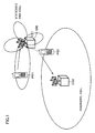
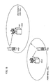
- Fig. 1 is a conceptual view for illustrating a directivity in uplink communication of a radio system according to a first embodiment of the invention.
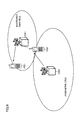
- Fig. 2 illustrates directivity control in downlink communication according to the first embodiment of the invention.
- the invention is not necessarily restricted to the PHS, but the PHS will now be described as an example of a radio system according to the invention.
- a radio base station 1000 of the first embodiment performs adaptive array processing for performing reception with a directivity when it receives a signal from a user terminal PS1 in its own cell, i.e., when base station 1000 performs uplink communication.
- This structure can suppress an interference signal from a user terminal PS2 in a peripheral cell, and therefore can prevent lowering of communication quality of the user in its own cell.
- radio base station 1000 performs non-directional transmission when base station 1000 transmits a signal to user terminal PS1 in its own cell, i.e., when base station 1000 performs downlink communication.
- the downlink communication is performed without performing the adaptive array processing, and therefore an adaptive array processing circuit for the downlink communication is not required so that an installation cost of such a circuit can be eliminated.
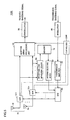
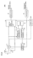
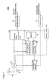
- Fig. 3 is a schematic block diagram illustrating a structure of radio base station 1000 performing the directivity control already described with reference to Figs. 1 and 2.
- radio base station 1000 includes an adaptive array antenna 10 having a plurality of antennas #1 - #n, a switch circuit 12.1, which sends a signal received by antenna #1 to radio base station 1000 for performing the adaptive array processing in the receive operation, and provides selectively a transmission signal (i.e., signal to be sent) to antenna #1 in the transmission operation, an adaptive array processing unit 20, which receives the signal sent from switch circuit 12.1 and signals sent from antennas #2 - #n, perform the adaptive array processing on the signals received by the plurality of antennas #1 - #n, and thereby performs selective separation and extraction of the signal sent from a desired user terminal, a demodulator 30, which receives an output of adaptive array processing unit 20, and performs demodulation and extraction of a baseband signal, a modulator 40, which receives and modulates a baseband signal for transmission, a transmission amplifier 50, which receives an output of modulator 40, amplifies a transmission signal and provides the amplified signal to switch circuit 12.1 corresponding to antenna #1, and
- radio base station 1000 Functions of radio base station 1000, which will be described below, may be achieved by a processor, which is arranged in control unit CNP for successively executing a series of procedures described by a computer program, and particularly by controlling operations of various components of radio base station 1000 by this processor, although the invention is not restricted to this.
- This program can be installed into control portion CNP from a record medium bearing the program.
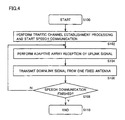
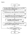
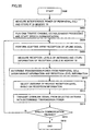
- Fig. 4 is a flowchart illustrating the operation of radio base station 1000 illustrated in Fig. 3.
- step S 100 when speech communication processing starts (step S 100), communication establishing processing is performed for starting the speech communication (S 102).
- control unit CNP controls switch circuit 12.1 and adaptive array processing unit 20 to perform adaptive array receive processing on the uplink signal (step S104).
- control unit CNP controls switch circuit 12.1 to transmit a signal provided from transmission amplifier 50 via antenna #1 (step S106).
- step S108 it is determined whether the speech communication state is already finished or not. If not, the processing returns to step S104.
- step S108 When it is determined in step S108 that the speech communication state is already finished, the communication processing ends (step S 110).
- the above structure performs the adaptive array processing, and therefore can maintain high communication quality by suppressing interference signals coming from a peripheral cell.
- the adaptive array processing is eliminated, and therefore the adaptive array processing circuit can be eliminated so that the installation cost of the radio base station can be reduced.
- the antenna used for the non-directional transmission is a predetermined one antenna (e.g., antenna #1).
- antenna #1 among the plurality of antennas #1 - #n may not be the optimum antenna for the communication with a certain user terminal PS1.
- the antenna which is most suitable for communication with the radio terminal PS 1 within the station's own cell is selected and used in the downlink communication.
- Fig. 5 is a schematic block diagram illustrating a structure of a radio base station 1200 of the modification of the first embodiment.
- radio base station 1200 differs from that of radio base station 1000 in that switch circuits 12.1 - 12.n are provided for all antennas #1 - #n, respectively, and these switch circuits 12.1 - 12.n selectively transmit signals sent from antennas #1 - #n to internal circuits of radio base station 1200, or provides signals sent from internal circuits of radio base station 1200 to antennas #1 - #n, respectively.
- Radio base station 1200 further includes a reception level measuring device 60, which receives signals from switch circuits 12.1 - 12.n, and measures the reception signal levels, a memory 70 storing the reception level of each antenna obtained by reception level measuring device 60, an antenna selecting device 80 selecting the antenna of the highest reception level based on the information stored in memory 70, and a switch circuit 90, which receives an output of transmission amplifier 50, and is controlled by antenna selecting device 80 to provide the output of transmission amplifier 50 selectively to switch circuits 12.1 - 12.n corresponding to antennas #1 - #n, and particularly to the switch circuit corresponding to the antenna of the highest reception level.
- a reception level measuring device 60 which receives signals from switch circuits 12.1 - 12.n, and measures the reception signal levels
- a memory 70 storing the reception level of each antenna obtained by reception level measuring device 60
- an antenna selecting device 80 selecting the antenna of the highest reception level based on the information stored in memory 70
- a switch circuit 90 which receives an output of transmission amplifier 50, and is controlled by antenna selecting device 80 to
- Fig. 6 is a flowchart illustrating the operation of radio base station of the modification of the first embodiment illustrated in Fig. 5.
- step S200 processing of establishing a traffic channel is performed, and the speech communication starts (step S202).
- adaptive array reception of an uplink signal is performed (step S204).
- the reception levels of the respective antennas are measured, and memory 70 stores information of the antenna of the highest reception level (step S206).
- the downlink signal is transmitted via the antenna of the highest reception level (step S208).
- step S210 When the transmission is completed, it is then determined whether the speech communication state is finished or not (step S210). When the speech communication is not finished, the processing returns to step S204.
- the speech communication processing ends (step S212).
- the above structure maintains the communication quality by performing the adaptive array processing.
- the above structure transmits the signal by selectively using the antenna of the highest reception level. Therefore, the radio base station can maintain the quality of communication with the radio user terminal within the its own cell.
- the adaptive array processing is performed in the uplink communication, and the non-directional transmission is performed in the downlink communication. Further, in the downlink communication, a transmission power is controlled in accordance with a reception power in the uplink communication as described below.
- Fig. 7 is a conceptual view illustrating a transmission directivity in the uplink communication according to the second embodiment.
- Fig. 8 conceptually illustrates the transmission directivity in the downlink communication as well as a range of waves
- the transmission power in the downlink communication is suppressed within a level allowing communication of the user in the station's own cell so that the interference with the peripheral cell is reduced, and the reduction in communication quality of the peripheral cell user can be prevented. Further, in the downlink communication, the adaptive array processing is not performed so that the adaptive array processing circuit corresponding to the downlink communication can be eliminated, and therefore the installation cost of a base station 2000 can be reduced.
- Fig. 9 is a schematic block diagram illustrating a structure of radio base station 2000 of the second embodiment illustrated in Figs. 7 and 8.
- radio base station 2000 includes reception level measuring device 60, which receives signals from respective antennas #1 - #n, and measures the reception levels thereof, memory 70 storing a conversion table, which represents a relationship of the reception level measured by reception level measuring device 60 with respect to the preset reception level and the transmission power (and will be referred to as a "reception level/transmission power conversion table"), and a transmission power calculator 100, which calculates the transmission power from the reception level of the predetermined antenna (e.g., antenna #1) based on the reception level/transmission power conversion table in memory 70, and controls the output level of transmission amplifier 50.
- reception level measuring device 60 which receives signals from respective antennas #1 - #n, and measures the reception levels thereof
- memory 70 storing a conversion table, which represents a relationship of the reception level measured by reception level measuring device 60 with respect to the preset reception level and the transmission power (and will be referred to as a "reception level/transmission power conversion table"
- a transmission power calculator 100 which calculates the transmission power from the reception level
- the reception level/transmission power conversion table is prepared in advance by an experiment, in which the transmission power required for the communication with the terminal is determined with respect to the reception level, and is stored in memory 70, although another manner may be employed.
- Fig. 10 is a flowchart illustrating the operation of radio base station 2000 of the second embodiment illustrated in Fig. 9.
- step S300 when the speech communication processing starts (step S300), processing of establishing the traffic channel is performed, and the speech communication starts (step S302).
- the reception is performed by effecting the adaptive array processing on the uplink signal (step S304), and memory 70 stores results obtained by measuring the reception levels of the respective antennas (step S306).
- the transmission power is determined from the reception level information based on the reception level/transmission power conversion table (step S308), and the downlink signal is transmitted from predetermined antenna #1 with the transmission power suppressed to the power level, which is estimated from the reception level as the level required for the transmission (step S310).
- step S304 it is determined whether the speech communication is already finished or not. If not, the processing returns to step S304.
- step S308 When it is determined in step S308 that the communication is already finished, the speech communication processing ends (step S314).
- Fig. 11 is a schematic block diagram illustrating a structure of a radio base station 2200, which is a modification of radio base station 2000 of the second embodiment already described with reference to Fig. 9.
- radio base station 2200 differs from that of radio base station 2000 of the second embodiment illustrated in Fig. 9 in that switch circuits 12.1 - 12.n are provided corresponding to respective antennas #1 - #n for switching transmission paths of the signals to and from the antennas in the transmission and reception operations.
- radio base station 2200 includes antenna selecting device 80 for selecting the antenna of the highest reception level in accordance with the reception levels of the respective antennas stored in memory 70, and switch circuit 90 for providing the output of transmission amplifier to one of switch circuits 12.1 - 12.n, which corresponds to the antenna selected by antenna selecting device 80.
- radio base station 2000 of the second embodiment illustrated in Fig. 9. Other structures are the same as those of radio base station 2000 of the second embodiment illustrated in Fig. 9. The same portions bear the same reference numbers, and description thereof is not repeated.
- Fig. 12 is a flowchart illustrating the operation of radio base station 2200 of the modification of the second embodiment illustrated in Fig. 11.
- step S400 when the speech communication processing starts (step S400), processing of establishing a traffic channel is performed, and the speech communication starts (step S402).
- adaptive array reception of an uplink signal is performed, and the signal sent from the user is separated (step S404).
- the reception levels of the respective antennas are measured, and memory 70 stores information of the reception levels (step S406).
- the transmission power which is required for the transmission, is determined from the reception level information according to the reception level/transmission power conversion table in memory 70 (step S408). Further, the antenna of the highest reception level is selected from the reception level information (step S410), and the downlink signal is transmitted from the selected antenna with the transmission power determined in step S408 (step S412).
- step S414 it is determined whether the speech communication is already finished or not.
- the processing returns to step S404.
- step S414 When it is determined in step S414 that the speech communication is already finished, the speech communication processing ends (step S416).
- the structure described above can maintain the communication quality in both the uplink communication and downlink communication, and can suppress the interference with the peripheral cell.
- the radio base station suppresses the transmission power in accordance with the reception level related to the terminal in the station's own cell.
- the level of the interference power provided from the peripheral cell may be low, e.g., in such a case that a distance to a base station of the peripheral cell is relatively large. If the above level is low, it is not necessary in some cases to suppress the transmission power level depending on only the reception level related to the terminal in the station's own cell.
- the adaptive array processing is performed in the uplink communication, and the non-directional transmission is performed in the downlink communication. Further, the downlink transmission power is controlled in accordance with the uplink reception power and the carrier sense level.
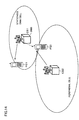
- Figs. 13 - 16 are conceptual views illustrating a method of controlling the transmission power and the transmission directivity according to the third embodiment.
- Figs. 13 and 14 illustrate a state, in which a distance to the peripheral cell is relatively short, and interference with a terminal PS2 in the peripheral cell may cause a problem.
- a radio base station 3000 of the third embodiment performs the adaptive array processing in the uplink communication operation of receiving the signal from terminal device PS 1 of the user in the station's own cell. Therefore, interference in the uplink communication can be suppressed so that lowering of communication quality of the user in the station's own cell can be prevented.
- the downlink transmission power in the downlink communication is suppressed to the level allowing communication of the user in the station's own cell. Therefore, the interference with the peripheral cell is reduced, and the lowering of the communication quality of the user in the peripheral cell can be prevented.
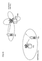
- Figs. 15 and 16 illustrate a state, in which the distance to the peripheral cell is relatively long, and the interference with terminal PS2 in the peripheral cell may cause a problem.
- Fig. 15 is a conceptual view illustrating a manner of suppressing interference in the uplink communication.
- a peripheral cell using the same frequency at the same time is remote from radio base station 3000.
- radio base station 3000 performs the reception with the transmission directivity when the uplink communication is performed with radio terminal PS 1 of the user in the station's own cell. Therefore, it is possible to suppress the interference from the peripheral cell, and thereby to maintain the communication quality of the user in the station's own cell.
- processing is performed based on the reception level of the signal, which is sent from user terminal PS1 in the station's own cell, to suppress the downlink transmission power to an extent allowing communication by the peripheral cell user.
- the extent of this suppression is controlled in accordance with the level of the carrier sense sensing the level of the signal provided from the peripheral cell, and the suppression is not performed to an extent exceeding the necessary extent. For example, it may be determined that the suppression of the transmission level can be eliminated without substantially affecting the communication with terminal PS2 in the peripheral cell. In this case, the downlink communication may be performed with the transmission power of the original or initial setting value.
- Fig. 17 is a schematic block diagram illustrating the structure of radio base station 3000 of the third embodiment illustrated in Figs. 13 to 16.
- reception level measuring device 60 measures not only the reception level of the signal coming from terminal PS 1 in the station's own cell but also the reception level of the signal coming from terminal PS2 in the peripheral cell, and stores them in memory 70.
- the "reception level/transmission power conversion table" stored in memory 70 is prepared to define the transmission power level corresponding to not only the reception level of the signal coming from the terminal in the station's own cell but also the received level of the signal coming from the peripheral cell.
- the "reception level/transmission power conversion table” is configured in advance by an experiment similarly to the second embodiment, and more specifically is configured such that, when the reception level of the signal coming from the peripheral cell takes a predetermined value (which is represented by PW1 in the following description) or more, the transmission power level initially taking a predetermined initial value is successively suppressed in accordance with increase in reception level of the signal coming from terminal PS1 in the station's own cell. It is also configured such that, when the reception level of the signal coming from the peripheral cell is lower than predetermined value PW1, the transmission power level maintains the predetermined initial value independently of the reception level of the signal coming from terminal PS1 in the station's own cell.
- a predetermined value which is represented by PW1 in the following description
- the structure of the "reception level/transmission power conversion table" is not restricted to the above, and it is merely required to suppress an influence, which is exerted by the downlink communication with terminal PS1 in the station's own cell on the communication between terminal PS2 in the peripheral cell and base station CS2 in the peripheral cell.
- the table may be configured such that, when the reception level obtained from the peripheral cell is lower than predetermined value PW1, the transmission power level increases from the predetermined initial value in accordance with the reception level of the signal coming from terminal PS1 in the station's own cell.
- transmission power calculator 100 controls the output level of transmission amplifier 50 by calculating the transmission power based on the reception level of the predetermined antenna (e.g., antenna #1) according to the reception level/transmission power conversion table in memory 70, which is preset as described above.
- radio base station 2000 of the second embodiment illustrated in Fig. 9. Other structures are the same as those of radio base station 2000 of the second embodiment illustrated in Fig. 9. The same portions bear the same reference numbers, and description thereof is not repeated.
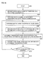
- Fig. 18 is a flowchart illustrating an operation of radio base station 3000 of the third embodiment illustrated in Fig. 17.
- reception level measuring device 60 measures the interference power applied from the peripheral cell based on the reception signals sent from antennas #1 - #n, and stores it in memory 70 (step S502). Subsequently, processing of establishing the traffic channel is performed, and the speech communication starts (step S504).
- the uplink signal is received by performing the adaptive array processing (step S506), and memory 70 stores measured reception levels of the respective antennas (step S508).
- the transmission power is determined according to the reception level/transmission power conversion table and based on the information thus stored in memory 70, i.e., based on the information of the interference power applied from the peripheral cell and the information of the reception level obtained from the terminal in the station's own cell (step S510).
- the transmission power is controlled to attain the power level, which is required for transmission according to estimation from the interference power and the reception level, and the downlink signal is sent from fixed antenna #1 with the transmission power thus calculated (step S512).
- step S514 When it is determined in step S514 that the speech communication is already finished, the speech communication processing ends (step S516).
- the structure described above can control the uplink communication and downlink communication as already described with reference to Figs. 13 to 16.
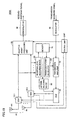
- Fig. 19 is a schematic block diagram illustrating a structure of a radio base station 3200, which is a modification of radio base station 3000 of the third embodiment illustrated in Fig. 17.
- radio base station 3200 differs from that of radio base station 3000 of the third embodiment in that switch circuits 12.1 - 12.n are provided for antennas #1 - #n, respectively, and signal transmission paths to or from the antennas in the transmission and reception operations are switched.
- radio base station 3200 includes antenna selecting device 80, which selects the antenna of the highest reception level in accordance with the reception level information in memory 70, i.e., the reception levels of respective antennas related to terminal PS 1 in the station's own cell, and switch circuit 90 providing the output of transmission amplifier 50 to one of switch circuits 12.1 - 12.n corresponding to the antenna, which is selected by the antenna selecting device 80.
- Fig. 20 is a flowchart illustrating an operation of radio base station 3200 of the third embodiment illustrated in Fig. 19.
- reception level measuring device 60 measures the interference power applied from the peripheral cell based on the reception signals sent from antennas #1 - #n, and stores it in memory 70 (step S602). Subsequently, processing of establishing the traffic channel is performed to start the speech communication (step S604).
- the uplink signal is received by performing the adaptive array processing (step S606), and measured reception levels of the respective antennas are stored in memory 70 (step S608).
- the transmission power is determined according to the reception level/transmission power conversion table and based on the information thus stored in memory 70, i.e., based on the information of the interference power applied from the peripheral cell and the information of the reception level obtained from the terminal in the station's own cell (step S610).
- Antenna selecting device 80 selects the antenna (e.g., antenna #1) of the highest reception level (step S612).
- the downlink signal is transmitted from antenna #1 of the highest reception level with the determined transmission power (step S614).
- step S616 it is determined whether the speech communication is already finished or not.
- the processing returns to step S606.
- step S616 When it is determined in step S616 that the speech communication is already finished, the speech communication processing ends (step S616).
- the structure described above can control the uplink communication and downlink communication as already described with reference to Figs. 13 to 16. Further, the downlink communication with terminal PS1 in the station's own cell is performed with the antenna of the highest reception level so that the quality of communication in the station's own cell can be kept high.
- the adaptive array reception is performed in the uplink communication with the terminal in the station's own cell so that the reception can be performed while suppressing the interference from the peripheral cell.
- the non-directional transmission is performed in the downlink communication so that the structure can be simple and inexpensive.
- the transmission power in the downlink communication is controlled to suppress the influence on the peripheral cell. Therefore, the communication quality of the whole system can be further improved.
- the adaptive array reception is performed in the uplink communication with the terminal in the station's own cell, the reception can be performed while suppressing the interference from the peripheral cell so that the invention can be effectively applied to the adaptive array radio device.
Landscapes
- Engineering & Computer Science (AREA)
- Computer Networks & Wireless Communication (AREA)
- Signal Processing (AREA)
- Mobile Radio Communication Systems (AREA)
- Radio Transmission System (AREA)
- Variable-Direction Aerials And Aerial Arrays (AREA)
Abstract
Description
Claims (18)
- A radio device comprising:an array antenna including a plurality of antennas (#1 - #n);a reception signal processing unit (20) multiplying signals provided from said respective antennas of said array antenna by reception weights, and thereby extracting a signal received from desired another radio device;first switch means (12.1) provided corresponding to at least one of said plurality of antennas for providing the signal received from the corresponding antenna to said reception signal processing unit in a receive operation; anda transmission signal processing unit (40) modulating and providing a transmission signal to said first switch means corresponding to the one antenna of said plurality of antennas, whereinsaid first switch means provides the signal received from said transmission signal processing unit to said corresponding antenna in a transmission operation.
- The radio device according to claim 1, wherein
said first switch means (12.1 - 12.n) are provided corresponding to said plurality of antennas, respectively, and
said radio device further comprises:reception level measuring means (60) for measuring reception levels of the signals transmitted from a terminal to be communicated with said radio device and received by said plurality of antennas, respectively;storage means (70) for storing results of the measurements of said reception level measuring means;antenna selecting means (80) for selecting the antenna having the maximum reception level from said plurality of antennas based on information stored in said storage means; andsecond switch means (90) for providing the signal provided from said transmission signal processing unit to said first switch means corresponding to the selected antenna in accordance with a result of selection by said antenna selecting means. - The radio device according to claim 1, further comprising:reception level measuring means (60) for measuring the reception level of the signal received by said plurality of antennas from a desired terminal to be communicated with said radio device;storage means (70) for storing a result of the measurement by said reception level measuring means and a transmission power level required in accordance with said reception level; andtransmission power calculating means (100) for controlling an output level of said transmission signal processing unit in accordance with the transmission power level determined based on the information stored in said storage means.
- The radio device according to claim 3, wherein
said reception level measuring means further measures a level of interference with respect to communication performed with the desired terminal,
said storage means stores the transmission power level required in accordance with said reception level and said interference level, and said interference level, and
said transmission power calculating means determines said transmission power level in accordance with said interference level and said reception level. - The radio device according to claim 1, wherein
said first switch means (12.1 - 12.n) are provided corresponding to said plurality of antennas, respectively, and
said radio device further comprises:reception level measuring means (60) for measuring levels of the signals sent from a terminal to be communicated with said radio device and received by said plurality of antennas;storage means (70) for storing a result of the measurement of said reception level measuring means and a transmission power level required in accordance with the reception level;transmission power calculating means (100) for controlling an output level of said transmission signal processing unit in accordance with the transmission power level determined based on the information stored in said storage means;antenna selecting means (80) selecting the antenna having the maximum reception level from said plurality of antennas based on the information stored in said storage means; andsecond switch means (90) providing the signal provided from said transmission signal processing unit to said first switch means corresponding to the selected antenna in accordance with a result of selection of said antenna selecting means. - The radio device according to claim 5, wherein
said reception level measuring means further measures a level of interference with respect to communication performed with the desired terminal,
said storage means stores the transmission power level required in accordance with said reception level and said interference level, and said interference level, and
said transmission power calculating means determines said transmission power level in accordance with said interference level and said reception level. - A transmission and reception directivity control method of a radio device (1000) with an array antenna including a plurality of antennas (#1 - #n), comprising the steps of:multiplying signals provided from said respective antennas of said array antenna by reception weights, and thereby performing separation and extraction of a signal received from desired another radio device;modulating a transmission signal; andproviding said modulated transmission signal to one of said plurality of antennas.
- The transmission and reception directivity control method according to claim 7, further comprising the steps of:measuring reception levels of signals sent from a terminal to be communicated with said radio device and received by said plurality of antennas;storing the measured reception levels;selecting the antenna having the maximum reception level from said plurality of antennas based on said stored reception levels; andproviding said modulated transmission signal to the selected antenna.
- The transmission and reception directivity control method according to claim 7, further comprising the steps of:measuring reception levels of signals sent from a desired terminal to be communicated with said radio device and received by said plurality of antennas;storing said reception levels and transmission power levels required according to the reception levels;determining the transmission power level based on said reception level and the transmission power level required according to the reception level; andcontrolling a level of output of said modulated transmission signal according to said determined transmission power level.
- The transmission and reception directivity control method according to claim 9, further comprising the steps of:measuring the level of interference with respect to the communication performed with said desired terminal, whereinsaid step of storing includes the step of:storing the transmission power level required according to said measured reception level and said interference level, and said interference level, andsaid step of determining said transmission power level includes the step of:determining said transmission power level according to the interference level and the reception level.
- The transmission and reception directivity control method according to claim 7, further comprising the steps of:measuring levels of signals sent from a desired terminal to be communicated with said radio device and received by said plurality of antennas;storing said measured reception levels and transmission power levels required according to said reception levels;determining the transmission power level based on said stored reception level and the transmission power level required according to said reception level;controlling an output level of said transmission signal according to said determined transmission power level;selecting the antenna having the maximum reception level from said plurality of antennas based on said measured reception levels; andproviding said transmission signal to said selected antenna.
- The transmission and reception directivity control method according to claim 11, further comprising the steps of:measuring the level of interference with respect to the communication performed with said desired terminal, whereinsaid step of storing includes the step of:storing the transmission power level required according to said reception level and said interference level, and said interference level, andsaid step of determining said transmission power level includes the step of:determining said transmission power level according to the interference level and the reception level.
- A transmission and reception directivity control program of a radio device (1000) with an array antenna including a plurality of antennas (#1 - #n), causing a computer to execute the steps of:multiplying signals provided from said respective antennas of said array antenna by reception weights, and thereby performing separation and extraction of a signal received from desired another radio device;modulating a transmission signal; andproviding said modulated transmission signal to one of said plurality of antennas.
- The transmission and reception directivity control program according to claim 13, further causing the computer to execute the steps of:measuring reception levels of signals sent from a terminal to be communicated with said radio device and received by said plurality of antennas;storing the measured reception levels;selecting the antenna having the maximum reception level from said plurality of antennas based on said stored reception levels; andproviding said modulated transmission signal to the selected antenna.
- The transmission and reception directivity control program according to claim 13, further causing the computer to execute the steps of:measuring reception levels of signals sent from a desired terminal to be communicated with said radio device and received by said plurality of antennas;storing said reception levels and transmission power levels required according to the reception levels;determining the transmission power level based on said reception level and the transmission power level required according to the reception level; andcontrolling a level of output of said modulated transmission signal according to said determined transmission power level.
- The transmission and reception directivity control program according to claim 15, further causing the computer to execute the steps of:measuring the level of interference with respect to the communication performed with said desired terminal, whereinsaid step of storing includes the step of:storing the transmission power level required according to said measured reception level and said interference level, and said interference level, andsaid step of determining said transmission power level includes the step of:determining said transmission power level according to the interference level and the reception level.
- The transmission and reception directivity control program according to claim 13, further operating the computer to execute the steps of:measuring levels of signals sent from a desired terminal to be communicated with said radio device and received by said plurality of antennas;storing said measured reception levels and transmission power levels required according to said reception levels;determining the transmission power level based on said stored reception level and the transmission power level required according to said reception level;controlling an output level of said transmission signal according to said determined transmission power level;selecting the antenna having the maximum reception level from said plurality of antennas based on said measured reception levels; andproviding said transmission signal to said selected antenna.
- The transmission and reception directivity control program according to claim 17, further causing the computer to execute the steps of:measuring the level of interference with respect to the communication performed with said desired terminal, whereinsaid step of storing includes the step of:storing the transmission power level required according to said reception level and said interference level, and said interference level, andsaid step of determining said transmission power level includes the step of:determining said transmission power level according to the interference level and the reception level.
Applications Claiming Priority (3)
| Application Number | Priority Date | Filing Date | Title |
|---|---|---|---|
| JP2002081458 | 2002-03-22 | ||
| JP2002081458A JP2003283411A (en) | 2002-03-22 | 2002-03-22 | Wireless device, transmission / reception directivity control method, and transmission / reception directivity control program |
| PCT/JP2003/002884 WO2003081808A1 (en) | 2002-03-22 | 2003-03-11 | Radio device, transmission/reception directivity control method, and transmission/reception directivity control program |
Publications (3)
| Publication Number | Publication Date |
|---|---|
| EP1496627A1 true EP1496627A1 (en) | 2005-01-12 |
| EP1496627A4 EP1496627A4 (en) | 2011-04-13 |
| EP1496627B1 EP1496627B1 (en) | 2013-11-13 |
Family
ID=28449121
Family Applications (1)
| Application Number | Title | Priority Date | Filing Date |
|---|---|---|---|
| EP03744993.1A Expired - Lifetime EP1496627B1 (en) | 2002-03-22 | 2003-03-11 | Radio device, transmission/reception directivity control method, and transmission/reception directivity control program |
Country Status (6)
| Country | Link |
|---|---|
| US (2) | US7248898B2 (en) |
| EP (1) | EP1496627B1 (en) |
| JP (1) | JP2003283411A (en) |
| CN (1) | CN100468991C (en) |
| AU (1) | AU2003211609A1 (en) |
| WO (1) | WO2003081808A1 (en) |
Families Citing this family (16)
| Publication number | Priority date | Publication date | Assignee | Title |
|---|---|---|---|---|
| JP3802488B2 (en) * | 2000-12-27 | 2006-07-26 | 三洋電機株式会社 | Wireless device, swap detection method, and swap detection program |
| EP1533917A1 (en) * | 2003-11-18 | 2005-05-25 | Mitsubishi Electric Information Technology Centre Europe B.V. | Antenna diversity switch for a receiver system and method using this switch |
| EP1533916A1 (en) * | 2003-11-18 | 2005-05-25 | Mitsubishi Electric Information Technology Centre Europe B.V. | Diversity switch combiner |
| EP1715600A1 (en) * | 2004-02-26 | 2006-10-25 | Matsushita Electric Industrial Co., Ltd. | Mobile station device and transmission antenna selection method in the mobile station device |
| WO2006013677A1 (en) | 2004-08-06 | 2006-02-09 | Brother Kogyo Kabushiki Kaisha | Radio receiving apparatus |
| US9002299B2 (en) * | 2004-10-01 | 2015-04-07 | Cisco Technology, Inc. | Multiple antenna processing on transmit for wireless local area networks |
| JP2006319710A (en) | 2005-05-13 | 2006-11-24 | Brother Ind Ltd | RFID tag communication system |
| JP4789064B2 (en) * | 2006-02-17 | 2011-10-05 | ブラザー工業株式会社 | Wireless tag communication device |
| US7738907B2 (en) * | 2006-06-20 | 2010-06-15 | Motorola, Inc. | Method and apparatus for uplink power control in a frequency division multiple access communication system |
| JP2008160569A (en) * | 2006-12-25 | 2008-07-10 | Kyocera Corp | OFDM communication system, base station, terminal, and communication method |
| JP5008994B2 (en) | 2007-01-30 | 2012-08-22 | 京セラ株式会社 | Communication system, base station, terminal and communication method |
| US20080233869A1 (en) * | 2007-03-19 | 2008-09-25 | Thomas Baker | Method and system for a single-chip fm tuning system for transmit and receive antennas |
| EP2192814A4 (en) * | 2007-09-11 | 2014-03-19 | Fujitsu Ltd | WIRELESS BASE STATION AND ITS CONTROL METHOD |
| JP2015159421A (en) * | 2014-02-24 | 2015-09-03 | パナソニック株式会社 | Wireless communication apparatus and directivity control method |
| JP6559320B2 (en) * | 2016-02-19 | 2019-08-14 | 京セラ株式会社 | Base station and transmission antenna determination method |
| KR102622030B1 (en) * | 2018-11-26 | 2024-01-08 | 삼성전자 주식회사 | Apparatus and method for selecting receive beam based on artificial neural network |
Family Cites Families (17)
| Publication number | Priority date | Publication date | Assignee | Title |
|---|---|---|---|---|
| US5768684A (en) * | 1994-03-04 | 1998-06-16 | Motorola, Inc. | Method and apparatus for bi-directional power control in a digital communication system |
| JPH11252614A (en) * | 1998-03-05 | 1999-09-17 | Kokusai Electric Co Ltd | Communication system, base station device and mobile station device |
| JPH11281725A (en) * | 1998-03-26 | 1999-10-15 | Nec Corp | Multi-propagation wave parameter measurement method and apparatus, and machine-readable recording medium recording program |
| US6144861A (en) * | 1998-04-07 | 2000-11-07 | Telefonaktiebolaget Lm Ericsson | Downlink power control in a cellular mobile radio communications system |
| US6615024B1 (en) * | 1998-05-01 | 2003-09-02 | Arraycomm, Inc. | Method and apparatus for determining signatures for calibrating a communication station having an antenna array |
| DE19820460C2 (en) * | 1998-05-07 | 2000-03-30 | Siemens Ag | Cellular base station with adaptive antenna |
| CN100413147C (en) * | 1998-07-13 | 2008-08-20 | Ntt移动通信网株式会社 | adaptive array antenna |
| JP2000216724A (en) * | 1999-01-26 | 2000-08-04 | Mitsubishi Electric Corp | Mobile communication system and communication method therefor |
| JP3258973B2 (en) * | 1999-03-24 | 2002-02-18 | 三洋電機株式会社 | Transmission channel allocation method and wireless device using the same |
| EP1187354B1 (en) * | 1999-03-30 | 2005-11-23 | Sanyo Electric Co., Ltd. | Radio device and method of calibration of antenna directivity |
| WO2000079702A1 (en) * | 1999-06-23 | 2000-12-28 | Japan As Represented By President Of Hokkaido University | Radio device |
| JP2001111464A (en) * | 1999-10-08 | 2001-04-20 | Matsushita Electric Ind Co Ltd | Base station device and method for radio transmission |
| JP3872953B2 (en) * | 1999-12-27 | 2007-01-24 | 株式会社東芝 | Wireless communication device using adaptive antenna |
| JP2001203620A (en) * | 2000-01-19 | 2001-07-27 | Matsushita Electric Ind Co Ltd | Wireless base station device and wireless communication method |
| KR100527801B1 (en) * | 2000-07-14 | 2005-11-15 | 산요덴키가부시키가이샤 | Mobile communication terminal and communication method |
| EP1248386A4 (en) * | 2000-12-21 | 2004-09-01 | Matsushita Electric Industrial Co Ltd | BASE STATION DEVICE |
| US7039363B1 (en) * | 2001-09-28 | 2006-05-02 | Arraycomm Llc | Adaptive antenna array with programmable sensitivity |
-
2002
- 2002-03-22 JP JP2002081458A patent/JP2003283411A/en active Pending
-
2003
- 2003-03-11 WO PCT/JP2003/002884 patent/WO2003081808A1/en not_active Ceased
- 2003-03-11 AU AU2003211609A patent/AU2003211609A1/en not_active Abandoned
- 2003-03-11 EP EP03744993.1A patent/EP1496627B1/en not_active Expired - Lifetime
- 2003-03-11 CN CNB038066343A patent/CN100468991C/en not_active Expired - Fee Related
- 2003-03-11 US US10/508,557 patent/US7248898B2/en not_active Expired - Fee Related
-
2007
- 2007-02-09 US US11/704,355 patent/US7761116B2/en not_active Expired - Fee Related
Also Published As
| Publication number | Publication date |
|---|---|
| US20070135173A1 (en) | 2007-06-14 |
| JP2003283411A (en) | 2003-10-03 |
| US7248898B2 (en) | 2007-07-24 |
| US20060014497A1 (en) | 2006-01-19 |
| AU2003211609A1 (en) | 2003-10-08 |
| EP1496627A4 (en) | 2011-04-13 |
| CN100468991C (en) | 2009-03-11 |
| WO2003081808A1 (en) | 2003-10-02 |
| EP1496627B1 (en) | 2013-11-13 |
| CN1643821A (en) | 2005-07-20 |
| US7761116B2 (en) | 2010-07-20 |
Similar Documents
| Publication | Publication Date | Title |
|---|---|---|
| US7761116B2 (en) | Radio device, transmission and reception directivity control method and transmission and reception directivity control program | |
| JP4149516B2 (en) | Antenna assembly and associated method for wireless communication devices | |
| EP1039663A1 (en) | Base station device and radio communication method | |
| KR100737964B1 (en) | Mode Switching in Adaptive Array Communication Systems | |
| WO2003081806A1 (en) | Radio device, spatial path control method, and spatial path control program | |
| EP1185120A1 (en) | Base station apparatus and handover control method | |
| EP1228582A1 (en) | Downlink signal processing in cdma systems utilizing arrays of antennas | |
| US6754512B1 (en) | Wireless base station using adaptive array for spatial multiplexing | |
| JP2002513940A (en) | Method and apparatus for determining the direction of arrival of a signal | |
| US20040121740A1 (en) | Radio communication apparatus and method | |
| US7379749B2 (en) | Radio terminal apparatus and reception operation control program thereof | |
| JP2001148649A (en) | Wireless base station | |
| US7075909B1 (en) | Radio spectrum management apparatus for base stations | |
| KR20030077663A (en) | Radio base apparatus, communication channel allocation method, and allocation program | |
| CN101080939B (en) | Wireless line control station, base station, mobile station, mobile communication system, and mobile communication method | |
| KR100435795B1 (en) | Radio base station device and radio communication method | |
| KR20090116079A (en) | Beamforming System and Method of Base Station Controller | |
| JP3594527B2 (en) | Wireless communication quality measuring device, wireless communication quality measuring method, and receiving device | |
| US7305235B2 (en) | Antenna directivity control method and radio apparatus | |
| JPH10313472A (en) | Wireless base station device and wireless terminal device | |
| JP4173405B2 (en) | Communication terminal out-of-range determination method, communication terminal | |
| JP2002325062A (en) | Mobile communication system and mobile communication terminal device | |
| US7398098B2 (en) | Radio base apparatus, transmission power control method, and transmission power control program | |
| JP4414736B2 (en) | Wireless base station apparatus, adaptive array processing control method, and adaptive array processing control program | |
| EP1370104A1 (en) | Method and system for determining an antenna of a radio base station at a moving target area during handover |
Legal Events
| Date | Code | Title | Description |
|---|---|---|---|
| PUAI | Public reference made under article 153(3) epc to a published international application that has entered the european phase |
Free format text: ORIGINAL CODE: 0009012 |
|
| 17P | Request for examination filed |
Effective date: 20041020 |
|
| AK | Designated contracting states |
Kind code of ref document: A1 Designated state(s): AT BE BG CH CY CZ DE DK EE ES FI FR GB GR HU IE IT LI LU MC NL PT RO SE SI SK TR |
|
| AX | Request for extension of the european patent |
Extension state: AL LT LV MK |
|
| A4 | Supplementary search report drawn up and despatched |
Effective date: 20110314 |
|
| 17Q | First examination report despatched |
Effective date: 20110616 |
|
| REG | Reference to a national code |
Ref country code: DE Ref legal event code: R079 Ref document number: 60345293 Country of ref document: DE Free format text: PREVIOUS MAIN CLASS: H04B0007260000 Ipc: H01Q0001240000 |
|
| GRAP | Despatch of communication of intention to grant a patent |
Free format text: ORIGINAL CODE: EPIDOSNIGR1 |
|
| GRAJ | Information related to disapproval of communication of intention to grant by the applicant or resumption of examination proceedings by the epo deleted |
Free format text: ORIGINAL CODE: EPIDOSDIGR1 |
|
| RIC1 | Information provided on ipc code assigned before grant |
Ipc: H04B 7/06 20060101ALI20130426BHEP Ipc: H01Q 3/26 20060101ALI20130426BHEP Ipc: H01Q 1/24 20060101AFI20130426BHEP Ipc: H04W 52/42 20090101ALI20130426BHEP Ipc: H01Q 3/24 20060101ALI20130426BHEP Ipc: H04B 7/08 20060101ALI20130426BHEP |
|
| GRAP | Despatch of communication of intention to grant a patent |
Free format text: ORIGINAL CODE: EPIDOSNIGR1 |
|
| INTG | Intention to grant announced |
Effective date: 20130515 |
|
| INTG | Intention to grant announced |
Effective date: 20130613 |
|
| RAP1 | Party data changed (applicant data changed or rights of an application transferred) |
Owner name: HERA WIRELESS S.A. |
|
| RBV | Designated contracting states (corrected) |
Designated state(s): DE FI SE |
|
| GRAS | Grant fee paid |
Free format text: ORIGINAL CODE: EPIDOSNIGR3 |
|
| GRAA | (expected) grant |
Free format text: ORIGINAL CODE: 0009210 |
|
| AK | Designated contracting states |
Kind code of ref document: B1 Designated state(s): DE FI SE |
|
| REG | Reference to a national code |
Ref country code: DE Ref legal event code: R096 Ref document number: 60345293 Country of ref document: DE Effective date: 20140109 |
|
| REG | Reference to a national code |
Ref country code: SE Ref legal event code: TRGR |
|
| REG | Reference to a national code |
Ref country code: DE Ref legal event code: R097 Ref document number: 60345293 Country of ref document: DE |
|
| PLBE | No opposition filed within time limit |
Free format text: ORIGINAL CODE: 0009261 |
|
| STAA | Information on the status of an ep patent application or granted ep patent |
Free format text: STATUS: NO OPPOSITION FILED WITHIN TIME LIMIT |
|
| 26N | No opposition filed |
Effective date: 20140814 |
|
| REG | Reference to a national code |
Ref country code: DE Ref legal event code: R097 Ref document number: 60345293 Country of ref document: DE Effective date: 20140814 |
|
| PGFP | Annual fee paid to national office [announced via postgrant information from national office to epo] |
Ref country code: SE Payment date: 20180319 Year of fee payment: 16 |
|
| PGFP | Annual fee paid to national office [announced via postgrant information from national office to epo] |
Ref country code: DE Payment date: 20190404 Year of fee payment: 17 |
|
| REG | Reference to a national code |
Ref country code: SE Ref legal event code: EUG |
|
| PG25 | Lapsed in a contracting state [announced via postgrant information from national office to epo] |
Ref country code: FI Free format text: LAPSE BECAUSE OF NON-PAYMENT OF DUE FEES Effective date: 20190311 Ref country code: SE Free format text: LAPSE BECAUSE OF NON-PAYMENT OF DUE FEES Effective date: 20190312 |
|
| PGFP | Annual fee paid to national office [announced via postgrant information from national office to epo] |
Ref country code: FI Payment date: 20170712 Year of fee payment: 15 |
|
| REG | Reference to a national code |
Ref country code: DE Ref legal event code: R119 Ref document number: 60345293 Country of ref document: DE |
|
| PG25 | Lapsed in a contracting state [announced via postgrant information from national office to epo] |
Ref country code: DE Free format text: LAPSE BECAUSE OF NON-PAYMENT OF DUE FEES Effective date: 20201001 |